Embed Size (px)
Citation preview
Chapter 19 – Power (AC)
Introductory Circuit Analysis
Robert L. Boylestad
19.1 – Introduction
We will now examine the total power equation in a slightly different form and will introduce two additional types of power: apparent and reactive.
19.2 – General Equation
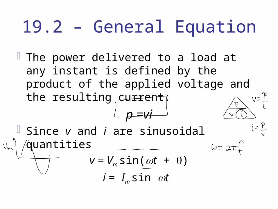
The power delivered to a load at any instant is defined by the product of the applied voltage and the resulting current:
p =viSince v and i are sinusoidal quantities
v = Vm sin(t + )
i = Im sin t

General Equation
The chosen v and i include all possibilities becauseIf the load is purely resistive, = 0°If the load is purely inductive, = 90° If the load is purely capacitive, = - 90°For a network that is primarily inductive,
is positive (v leads i)For a network that is primarily capacitive,
is negative (i leads v)
General Equation
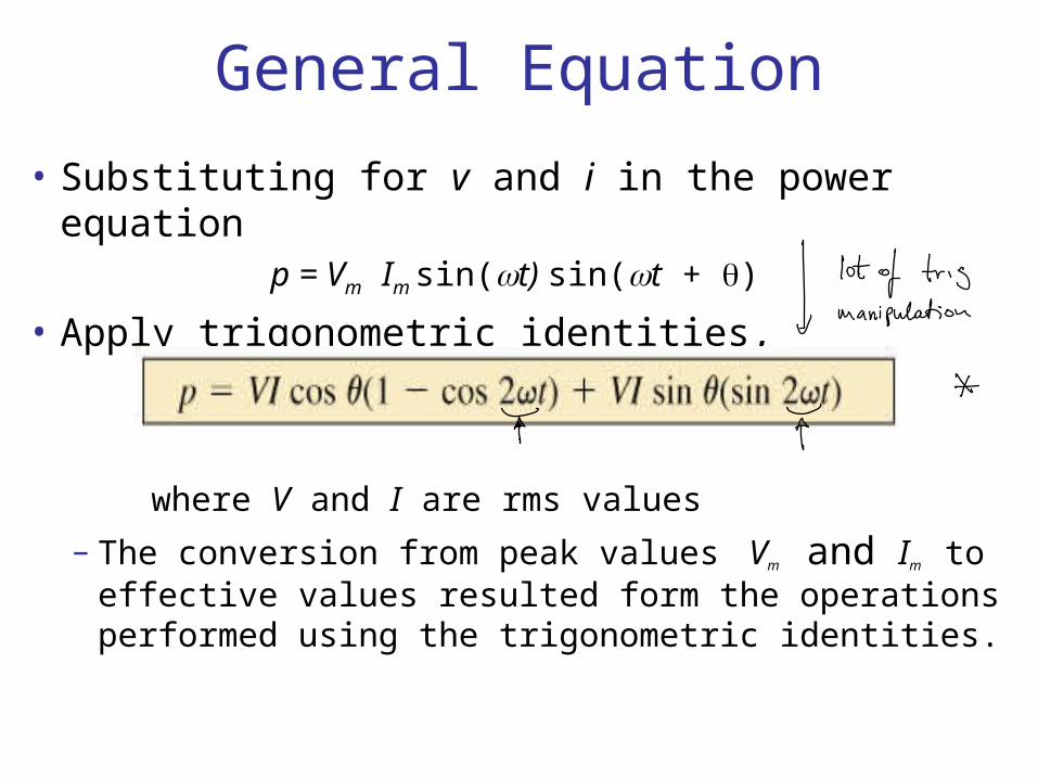
• Substituting for v and i in the power equationp = Vm Im sin(t) sin(t + )
• Apply trigonometric identities,
where V and I are rms values
– The conversion from peak values Vm and Im to effective values resulted form the operations performed using the trigonometric identities.

19.3 – Resistive CircuitFor a purely resistive circuit:
v and i are in phase, and = 0°, so power is:
where VI is the average or dc term. VIcos2t is a negative cosine wave with twice
the frequency of v or i and a peak value of VI.
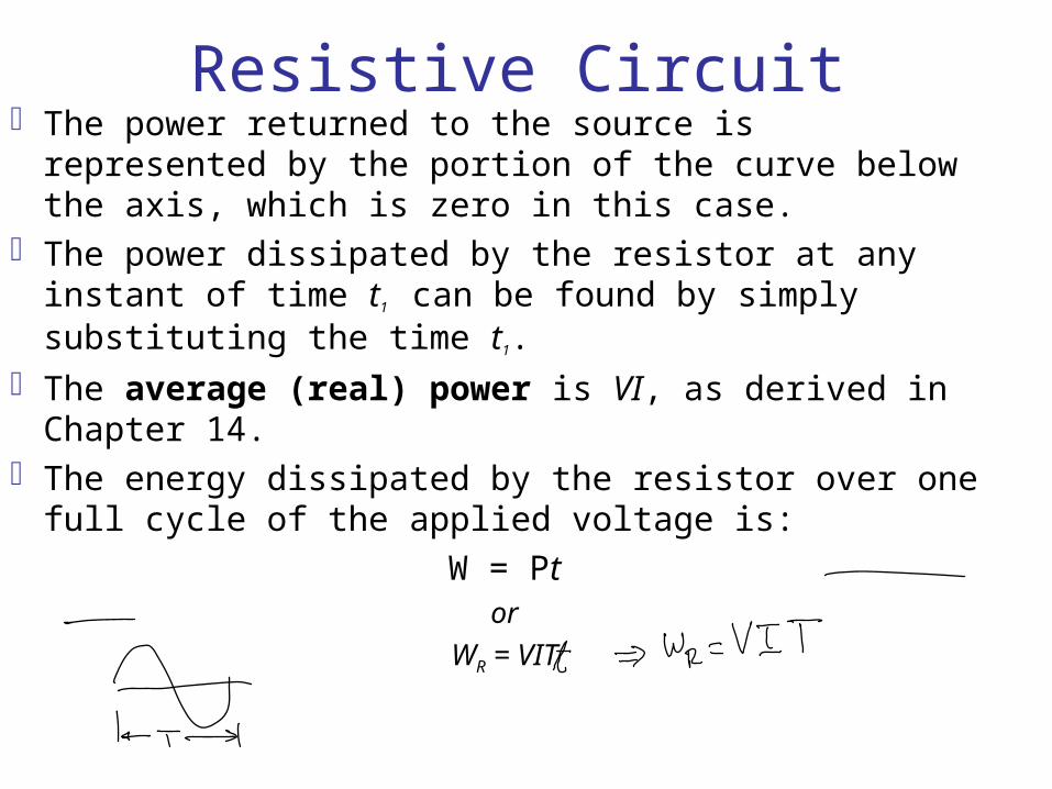
Resistive CircuitThe power returned to the source is represented by the
portion of the curve below the axis, which is zero in this case.
The power dissipated by the resistor at any instant of time t1 can be found by simply substituting the time t1.
The average (real) power is VI, as derived in Chapter 14.
The energy dissipated by the resistor over one full cycle of the applied voltage is:
W = Ptor
WR = VIT
19.4 – Apparent Power
From our analysis of dc networks (and resistive elements above), it would seem apparent that the power delivered to the load is simply determined by the product of the applied voltage and current, with no concern for the components of the load: that is, P = VI. However, the power factor (cos) of the load will have a pronounced effect on the power dissipated.
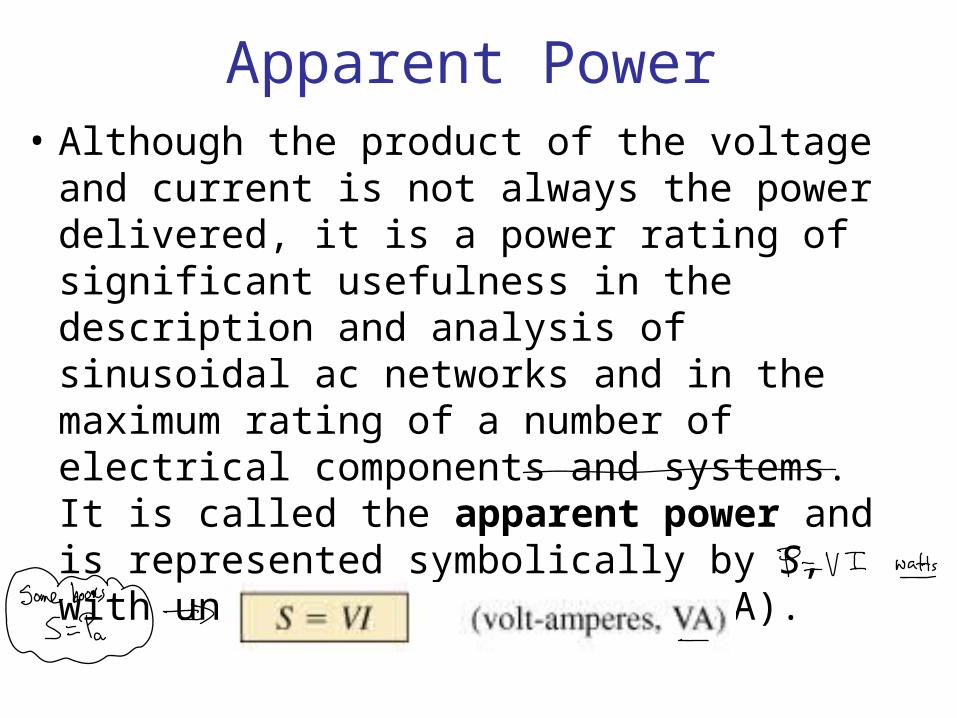
Apparent Power• Although the product of the voltage and
current is not always the power delivered, it is a power rating of significant usefulness in the description and analysis of sinusoidal ac networks and in the maximum rating of a number of electrical components and systems. It is called the apparent power and is represented symbolically by S, with units of volt-amperes (VA).
Apparent Power
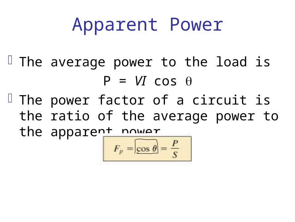
The average power to the load is
P = VI cos The power factor of a circuit is the ratio of the
average power to the apparent power.
Apparent PowerIn general, power equipment is rated in volt-
amperes (VA) or in kilovolt-amperes (kVA) and not in watts. By knowing the volt-ampere rating and the rated voltage of a device, we can readily determine the maximum current rating.
The exact current demand of a device, when used under normal operating conditions, could be determined if the wattage rating and power factor were given instead of the volt-ampere rating.
19.5 – Inductive Circuit and Reactive Power
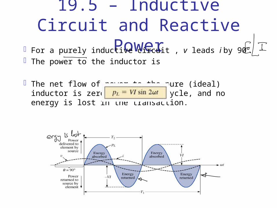
For a purely inductive circuit , v leads i by 90°.The power to the inductor is
The net flow of power to the pure (ideal) inductor is zero over a full cycle, and no energy is lost in the transaction.
Inductive Circuit and Reactive Power
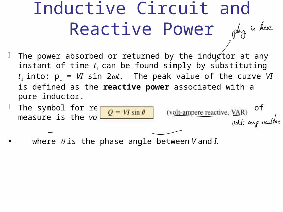
The power absorbed or returned by the inductor at any instant of time t1
can be found simply by substituting t1 into: pL = VI sin 2t. The peak value of the curve VI is defined as the reactive power associated with a pure inductor.
The symbol for reactive power is Q, and its unit of measure is the volt-ampere reactive (VAR):
• where is the phase angle between V and I.
Inductive Circuit and Reactive Power
If the average power is zero, and the energy supplied is returned within one cycle, why is a reactive power of any significance?
At every instant of time along the power curve that the curve is above the axis (positive), energy must be supplied to the inductor, even though it will be returned during the negative portion of the cycle. This power requirement during the positive portion of the cycle requires that the generating plant provide this energy during that interval, even though this power is not dissipated but simply “borrowed.”
Inductive Circuit and Reactive Power
The increased power demand during these intervals is a cost factor that must that must be passed on to the industrial consumer.
Most larger users of electrical energy pay for the apparent power demand rather than the watts dissipated since the volt-amperes used are sensitive to the reactive power requirement.
The closer the power factor of an industrial consumer is to 1, the more efficient is the plant’s operation since it is limiting its use of “borrowed” power.

Inductive Circuit and Reactive Power
The energy absorbed by the inductor during the positive portion of the cycle (Fig. 19.9) is equal to that returned during the negative portion and can be determined using the following equation:
W = Pt where P is the average value for the interval
and t is the associated interval of time.
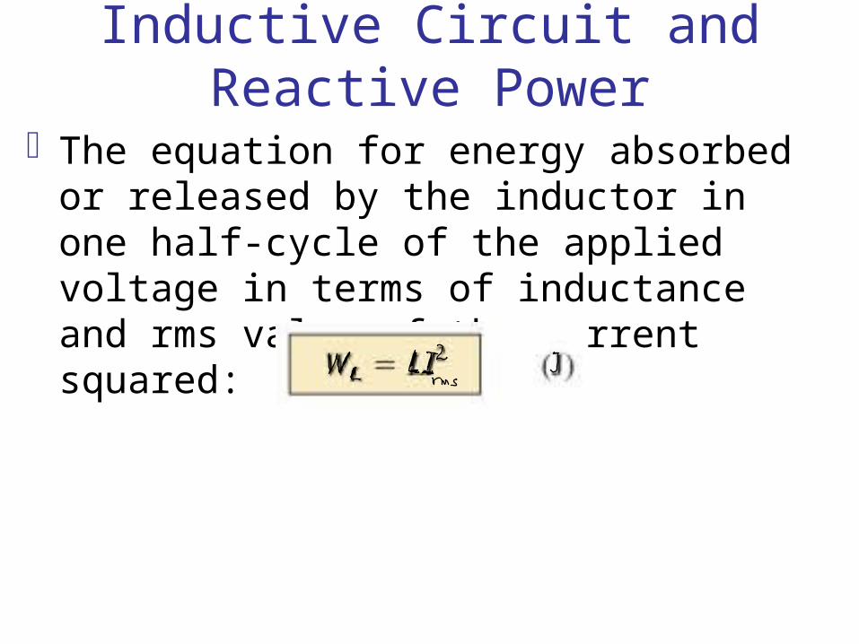
Inductive Circuit and Reactive Power
The equation for energy absorbed or released by the inductor in one half-cycle of the applied voltage in terms of inductance and rms value of the current squared:
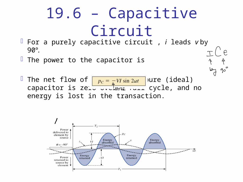
19.6 – Capacitive CircuitFor a purely capacitive circuit , i leads v by 90°.The power to the capacitor is
The net flow of power to the pure (ideal) capacitor is zero over a full cycle, and no energy is lost in the transaction.
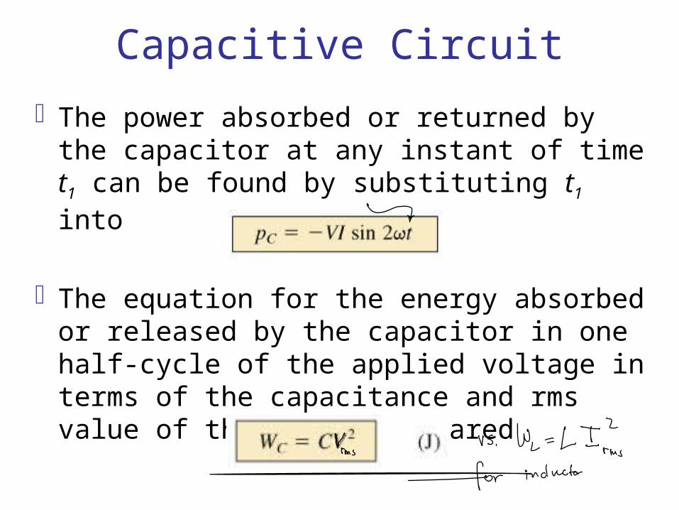
Capacitive Circuit
The power absorbed or returned by the capacitor at any instant of time t1 can be found by substituting t1 into
The equation for the energy absorbed or released by the capacitor in one half-cycle of the applied voltage in terms of the capacitance and rms value of the voltage squared
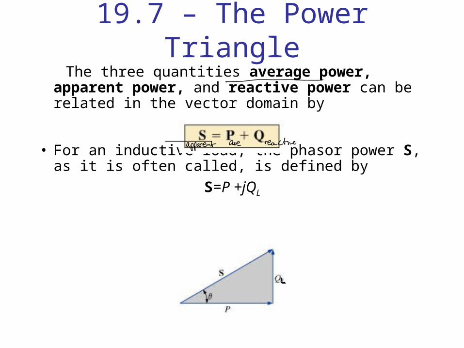
19.7 – The Power Triangle The three quantities average power, apparent
power, and reactive power can be related in the vector domain by
• For an inductive load, the phasor power S, as it is often called, is defined by
S=P +jQL

The Power TriangleThe 90°shift in QL from P is the source of another term
for reactive power: quadrature power.For a capacitive load, the phasor power S is defined by
S = P- jQC
The Power Triangle
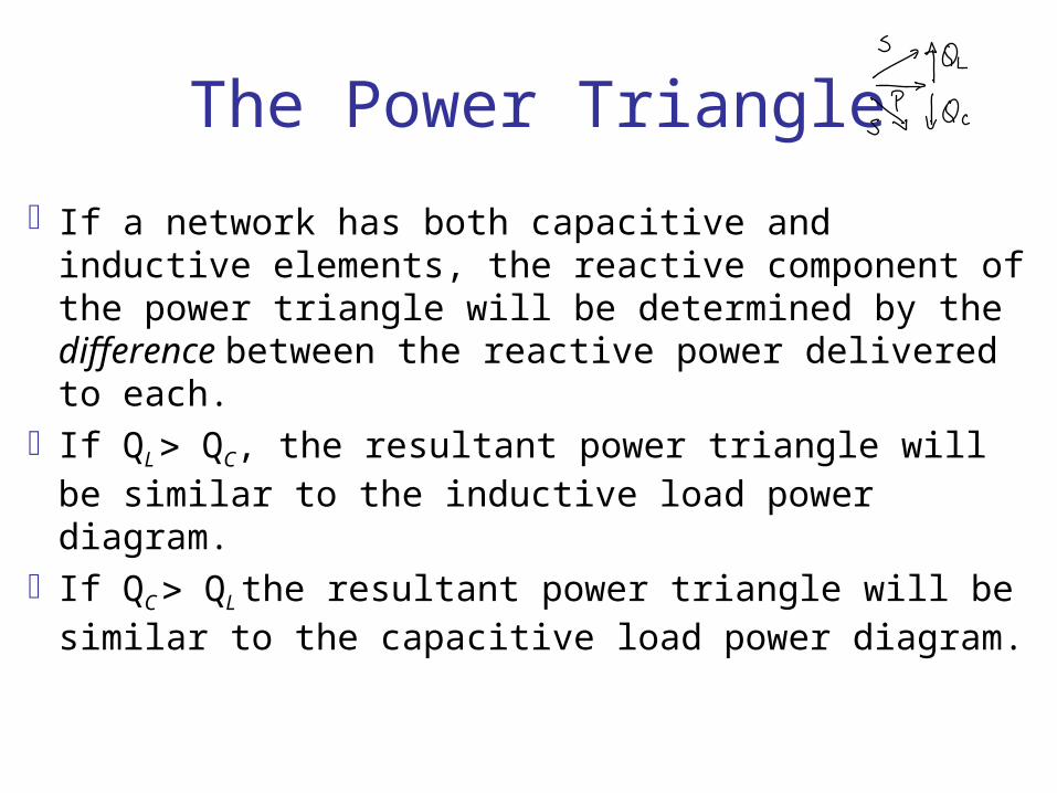
If a network has both capacitive and inductive elements, the reactive component of the power triangle will be determined by the difference between the reactive power delivered to each.
If QL QC, the resultant power triangle will be similar to the inductive load power diagram.
If QC QL the resultant power triangle will be similar to the capacitive load power diagram.
The Power Triangle
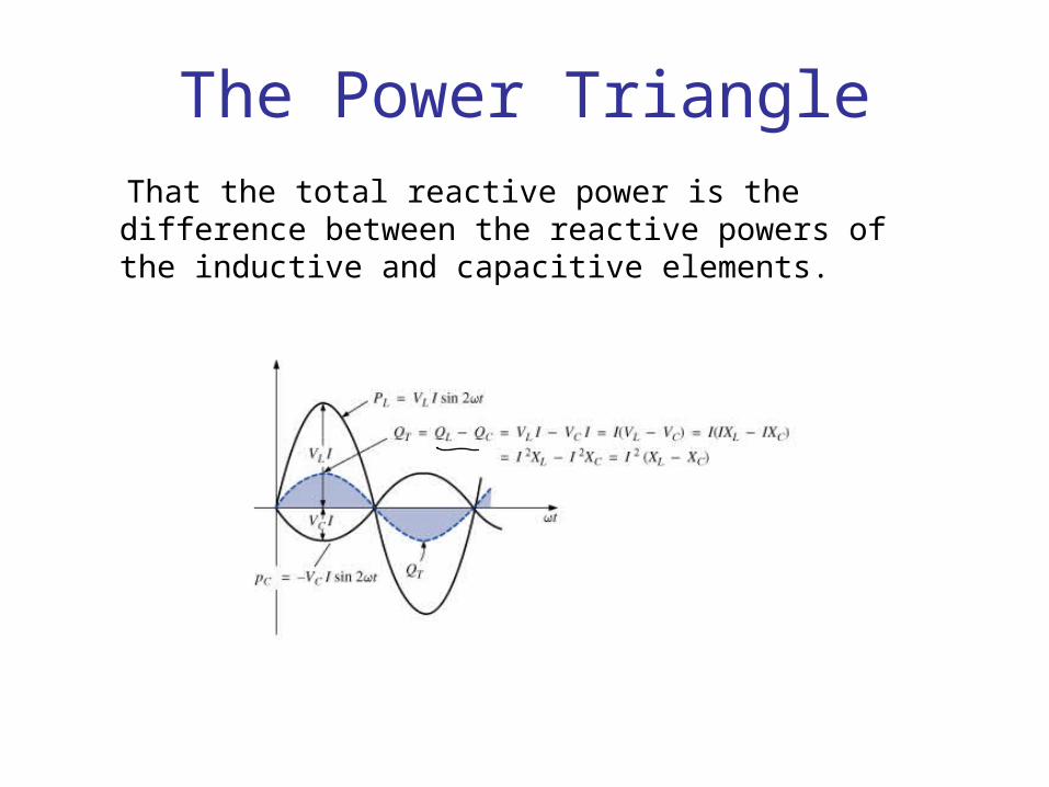
That the total reactive power is the difference between the reactive powers of the inductive and capacitive elements.
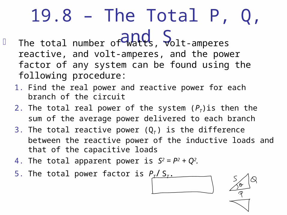
19.8 – The Total P, Q, and S The total number of watts, volt-amperes reactive, and
volt-amperes, and the power factor of any system can be found using the following procedure:
1. Find the real power and reactive power for each branch of the circuit
2. The total real power of the system (PT)is then the sum of the average power delivered to each branch
3. The total reactive power (QT ) is the difference between the reactive power of the inductive loads and that of the capacitive loads
4. The total apparent power is S2 = P2 + Q2.
5. The total power factor is PT/ ST.

The Total P, Q, and SThere are two important points in the previous
slide:First, the total apparent power must be determined
from the total average and reactive powers and cannot be determined from the apparent powers of each branch.
Second, and more important, it is not necessary to consider the series-parallel arrangement of branches In other words, the total real, reactive, or apparent power is independent of whether the loads are in series, parallel, or series-parallel.
19.9 – Power-Factor Correction
The design of any power transmission system is very sensitive to the magnitude of the current in the lines as determined by the applied loads.
Increased currents result in increased power losses (by a squared factor since P = I2R) in the transmission lines due to the resistance of the lines.
Heavier currents also require larger conductors, increasing the amount of copper needed for the system, and they require increased generating capacities by the utility company.

Power-Factor Correction
Since the line voltage of a transmission system is fixed, the apparent power is directly related to the current level.
In turn, the smaller the net apparent power, the smaller the current drawn from the supply. Minimum current is therefore drawn from a supply when S = P and QT = 0.
Power-Factor Correction
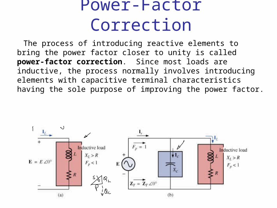
The process of introducing reactive elements to bring the power factor closer to unity is called power-factor correction. Since most loads are inductive, the process normally involves introducing elements with capacitive terminal characteristics having the sole purpose of improving the power factor.

19.10 – Power Meters
The electrodynamometer wattmeter introduced in previous chapters can be used to measure the power in a dc or an ac network using the same connection strategy.
It can be used to measure the wattage of any network with a periodic or a nonperiodic input.
Power Meters When using a wattmeter, the operator must take care not to
exceed the current, voltage, or wattage rating. The product of the voltage and current ratings may or may
not equal the wattage rating. In the high-power-factor wattmeter, the product of the
voltage and current ratings is usually equal to the wattage rating, or at least 80% of it.
For a lower-power-factor wattmeter, the product of the current and voltage ratings is much greater than the wattage rating.
The low-power-factor meter is used only in circuits with low power factors(total impedance highly reactive).
Power MetersPower-factor meters are designed to read the
power factor of a load under operating conditions. Most are designed to be used on single- or three-phase systems.
Both the voltage and the current are typically measured using nonintrusive methods.Connections are made directly to the terminals for
the voltage measurements.Clamp-on current transformers are used to sense
the current level.
19.11 – Effective Resistance The resistance of a conductor as determined by the
equation R = (l /A) is often called the dc, ohmic or geometric resistance. It is a constant quantity determined only by the material used and its physical dimensions.
In ac circuits, the actual resistance of a conductor (called the effective resistance) differs from the dc resistance because of the varying currents and voltages that introduce effects not present in dc circuits.
These effects include radiation losses, skin effect, eddy currents, and hysteresis losses. The first two effects apply to any network, while the latter two are concerned with the additional losses introduced by the presence of ferromagnetic materials in a changing magnetic field.

Effective ResistanceExperimental procedure
The effective resistance of an ac circuit cannot be measured by the ratio V/ since this ratio is now the impedance of a circuit that may have both resistance and reactance.
The effective resistance can be found by using the power equation P = 2R, where
A wattmeter and an ammeter are therefore necessary for measuring the effective resistance of an ac circuit.
Effective Resistance
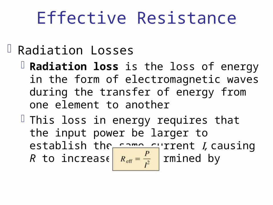
Radiation LossesRadiation loss is the loss of energy in the form
of electromagnetic waves during the transfer of energy from one element to another
This loss in energy requires that the input power be larger to establish the same current , causing R to increase as determined by
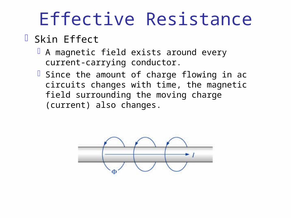
Effective ResistanceSkin Effect
A magnetic field exists around every current-carrying conductor.
Since the amount of charge flowing in ac circuits changes with time, the magnetic field surrounding the moving charge (current) also changes.
Effective ResistanceFor a conductor carrying alternating current, the
changing magnetic field surrounding the wire links the wire itself, thus developing within the wire an induced voltage that opposes the original flow of charge or current.
As the frequency increases the counter-induced voltage at the center of the wire will increase, to the point where current will flow only on the surface of the conductor.
At 60 Hz the skin effect is almost noticeable. The effect is very pronounced at radio frequencies.
The skin effect reduces the effective area of the conductor, resulting in increased resistance.
Effective ResistanceHysteresis and Eddy Current Losses
Hysteresis and eddy current losses will appear when a ferromagnetic material is placed in the region of a changing magnetic field.
As alternating current passes through the coil, it will develop a changing magnetic flux linking both the coil and the core that will develop an induced voltage within the core as determined by Faraday’s law.
This induced voltage and the geometric resistance of the core RC = (l /A) cause currents to be developed within the core, icore = (eind/RC ), called eddy currents.
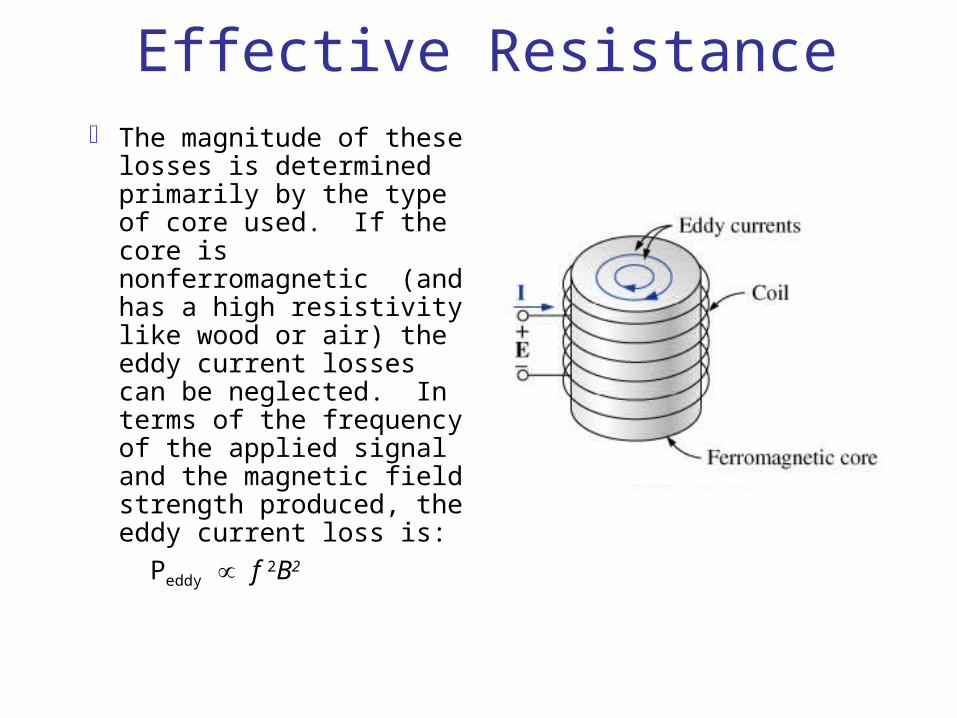
Effective Resistance The magnitude of these
losses is determined primarily by the type of core used. If the core is nonferromagnetic (and has a high resistivity like wood or air) the eddy current losses can be neglected. In terms of the frequency of the applied signal and the magnetic field strength produced, the eddy current loss is:
Peddy f 2B2
Effective Resistance
The hysteresis loss is proportional to the frequency to the 1st power times the magnetic field strength to the nth power:
Phys f1Bn
Hysteresis losses can be effectively reduced by the injection of small amounts of silicon into the magnetic core, constituting some 2% or 3% of the total composition of the core.
This must be done carefully, however, because too much silicon makes the core brittle and difficult to machine into the shape desired.


![Methods of Analysis and Selected Topics (dc) · Introductory Circuit Analysis, 12/e Boylestad Copyright ©2011 by Pearson Education, Inc. publishing as Pearson [imprint] MESH ANALYSIS](https://img.pdfslide.us/doc/110x75/5b45f95e7f8b9afb078b47dd/methods-of-analysis-and-selected-topics-dc-introductory-circuit-analysis.jpg)

![Chapter 2 · 2021. 3. 30. · Introductory Circuit Analysis, 12/e Boylestad Copyright ©2011 by Pearson Education, Inc. publishing as Pearson [imprint] BATTERY LIFE FACTORS • The](https://img.pdfslide.us/doc/110x75/614a50fa12c9616cbc69562d/chapter-2-2021-3-30-introductory-circuit-analysis-12e-boylestad-copyright.jpg)
![Series-Parallel Circuits · Introductory Circuit Analysis, 12/e Boylestad Copyright ©2011 by Pearson Education, Inc. publishing as Pearson [imprint] VOLTAGE …](https://img.pdfslide.us/doc/110x75/5b45f67f7f8b9a114c8b4d73/series-parallel-circuits-introductory-circuit-analysis-12e-boylestad-copyright.jpg)