Embed Size (px)
Citation preview
Chapter 19. LAVA R3X: the humanoid that walks and talks So far in this book, you’ve built vehicle robots, animal robots, and machines, but perhaps one of
the coolest robot projects you can make with your EV3 set is a humanoid robot that walks on
two legs. In this chapter, you’ll build and program LAVA R3X, shown in Figure 19-1. LAVA
R3X walks on two legs controlled by Large Motors, and it can move its head and arms using
the Medium Motor.

Figure 19-1. LAVA R3X walks around on two legs while moving its head and arms, and it greets you when you shake
its hand.
Once you’ve made the robot walk, you’ll be challenged to expand the program to make the
robot interactive and lifelike by using the techniques you’ve learned throughout this book.
LAVA R3X is able to walk by continuously shifting its weight to one foot while moving the
other foot forward. A mechanism in each leg turns the continuous forward motion of the motor

into an alternating forward and backward motion of the foot and an alternating left and right
tilting motion of the ankle (see Figure 19-2).
Figure 19-2. As the motor in each leg makes one complete rotation, the foot moves back and forth and the ankle tilts
to the left and to the right.
For the robot to walk in a stable manner, the mechanisms of both legs must be in the exact
opposite position, and the motors should turn at the same speed. When these requirements are
met, one foot is tilted so that it doesn’t touch the ground while it moves forward, while the other
foot is tilted so that it carries the robot’s weight while it pushes backward, thereby propelling
the robot forward.
As the motor in each leg makes one rotation, the mechanism moves left, right, forward, and
backward, after which it’s back in its initial orientation, having completed one step.
You’ll use the Touch Sensor between the robot’s legs to place the mechanisms in opposite
positions, just as you did for ANTY’s motors in Chapter 13, and you’ll create a speed controller
to ensure that both motors turn at the same speed.
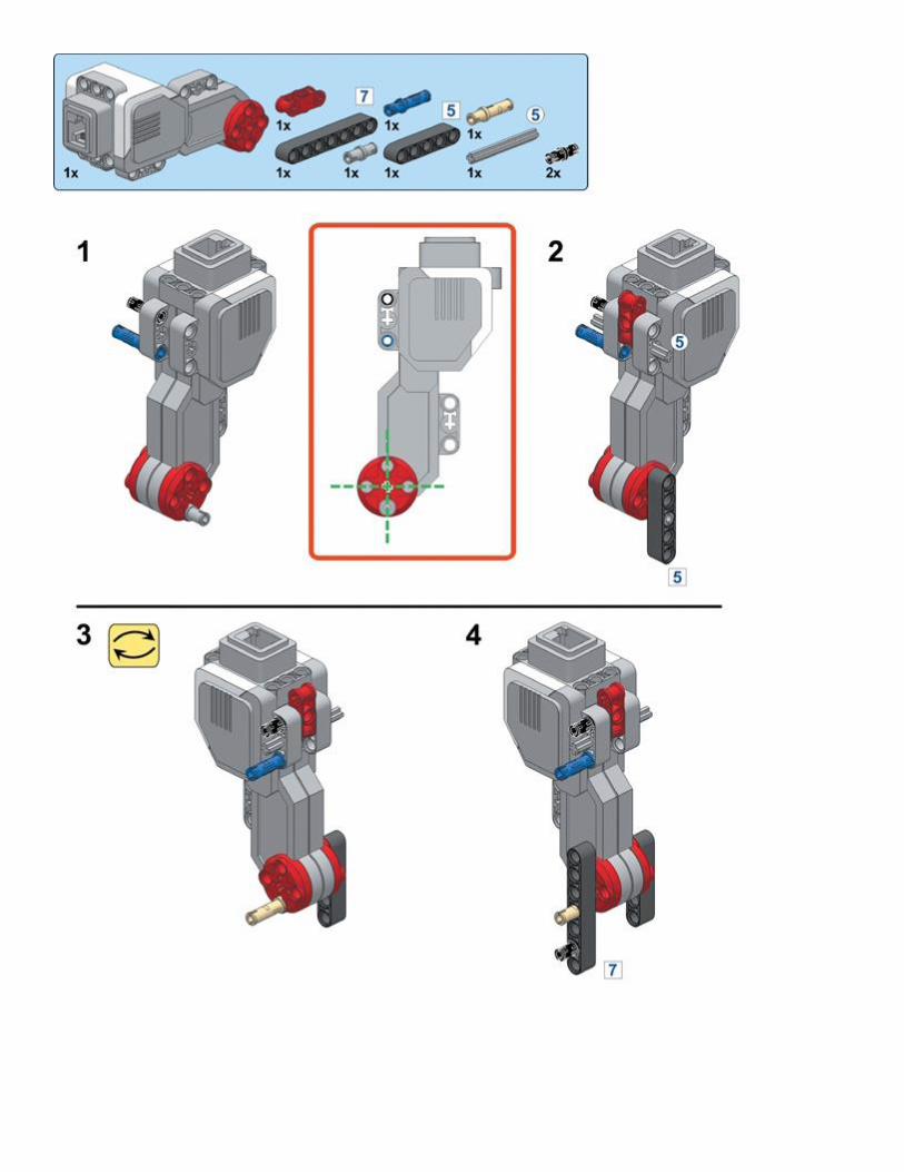
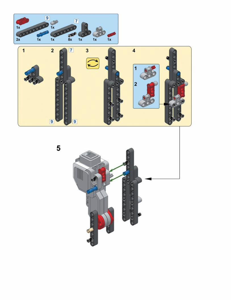
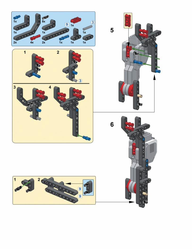
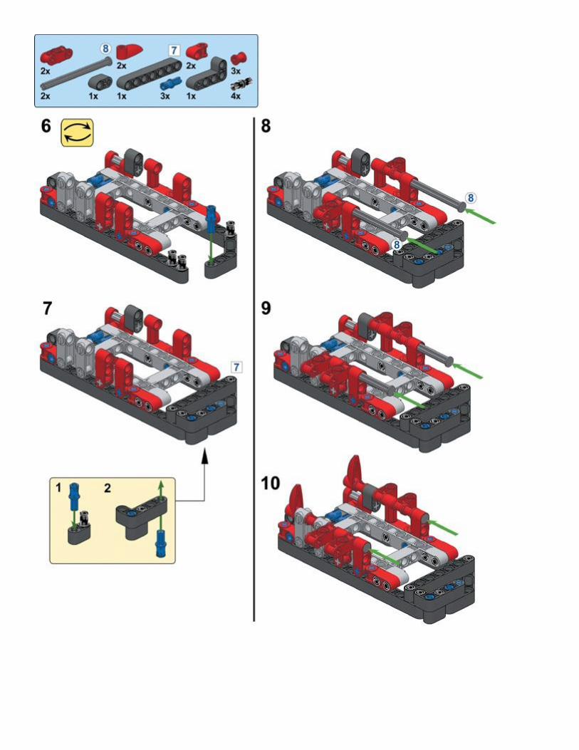
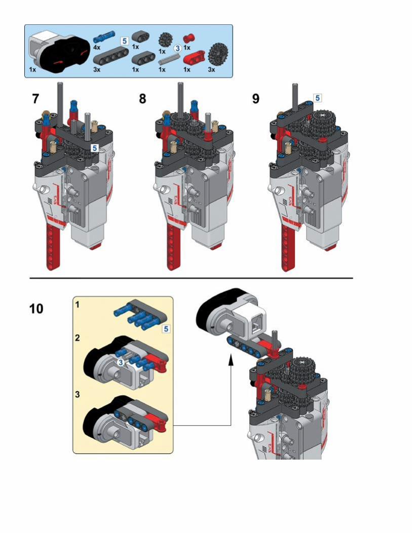
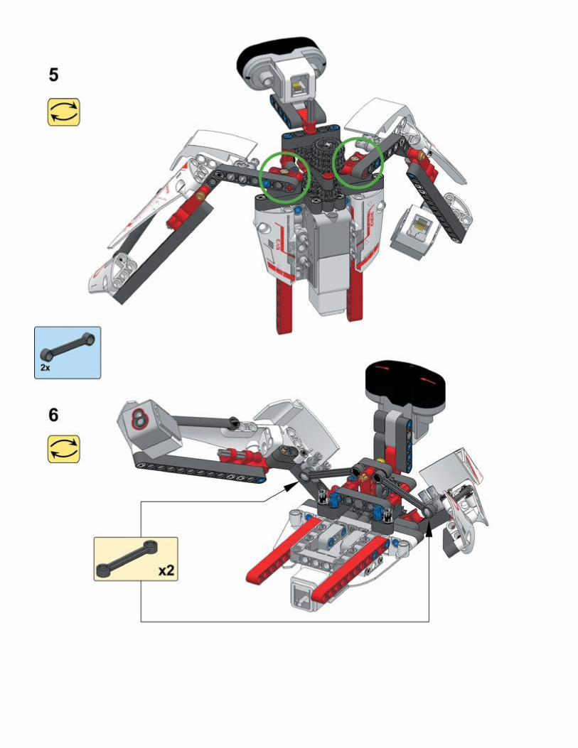
building the legs
First, you’ll build the robot’s legs and create My Blocks to make the robot walk and turn. Next,
you’ll build the robot’s upper body and create a program to make the robot interact with its

surroundings using sensors. Select the pieces you’ll need for the robot, shown in Figure 19-3,
and then follow the instructions on the next pages.
Figure 19-3. The pieces needed to build LAVA R3X. You should have a number of leftover pieces after you’ve built
the legs; you’ll use them to build the robot’s head and arms later.


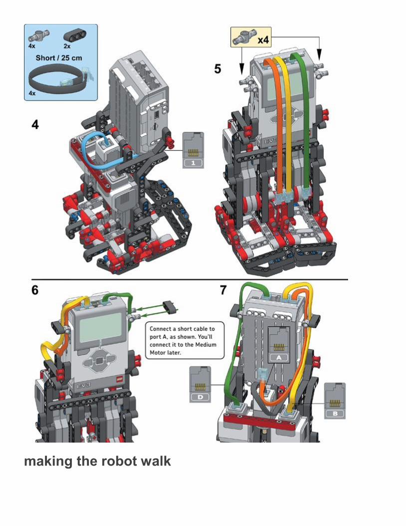
making the robot walk

You’ll now create several My Blocks to place the robot’s legs in opposite positions, to make the
robot walk forward, and to make the robot turn to the left. You’ll also make a small program to
test each block.
Testing these blocks without the robot’s top heavy upper body makes troubleshooting easier
because the robot is less likely to fall over. Once the robot walks in a stable manner using the
My Blocks, you’ll be ready to complete the design.
my block #1: reset
Each time a motor makes one complete rotation, the mechanism around this motor presses the
Touch Sensor once (see Figure 19-4). LAVA R3X can use this sensor information to place the
left and right leg in opposite positions.
Figure 19-4. As each of the motors makes a rotation, it pushes a black angled beam against a grey disk, which in turn presses the Touch Sensor. The tan axle ensures that the grey disk remains aligned properly.
Because the robot can’t detect which of the two leg mechanisms is pressing the Touch Sensor at
a given moment, it should first position the legs in such a way that neither mechanism presses
the sensor. To accomplish this, the robot moves the motors forward until the Touch Sensor is
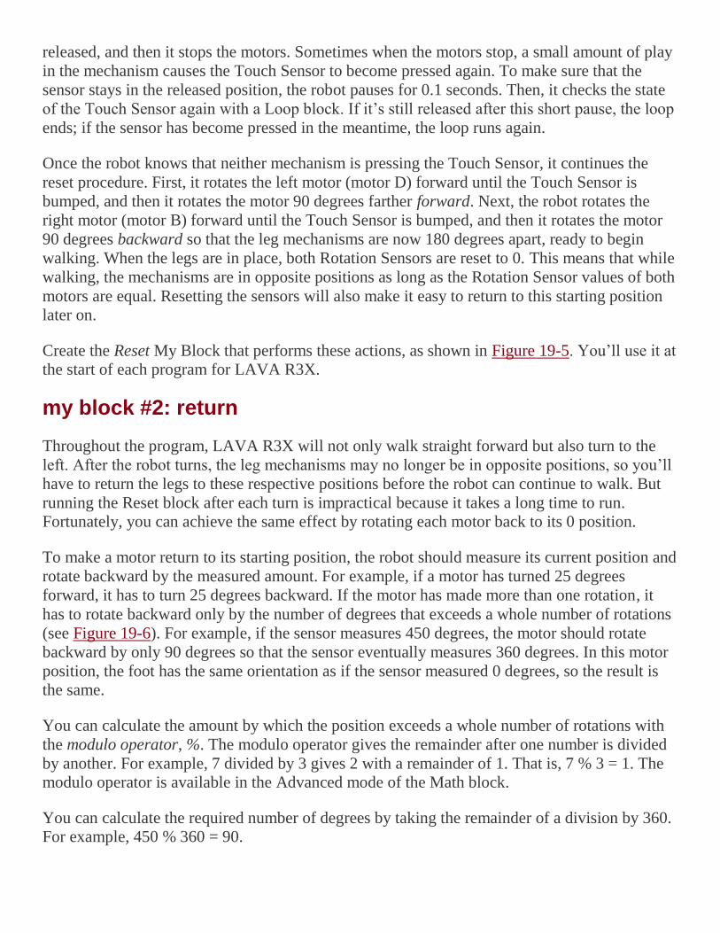
released, and then it stops the motors. Sometimes when the motors stop, a small amount of play
in the mechanism causes the Touch Sensor to become pressed again. To make sure that the
sensor stays in the released position, the robot pauses for 0.1 seconds. Then, it checks the state
of the Touch Sensor again with a Loop block. If it’s still released after this short pause, the loop
ends; if the sensor has become pressed in the meantime, the loop runs again.
Once the robot knows that neither mechanism is pressing the Touch Sensor, it continues the
reset procedure. First, it rotates the left motor (motor D) forward until the Touch Sensor is
bumped, and then it rotates the motor 90 degrees farther forward. Next, the robot rotates the
right motor (motor B) forward until the Touch Sensor is bumped, and then it rotates the motor
90 degrees backward so that the leg mechanisms are now 180 degrees apart, ready to begin
walking. When the legs are in place, both Rotation Sensors are reset to 0. This means that while
walking, the mechanisms are in opposite positions as long as the Rotation Sensor values of both
motors are equal. Resetting the sensors will also make it easy to return to this starting position
later on.
Create the Reset My Block that performs these actions, as shown in Figure 19-5. You’ll use it at
the start of each program for LAVA R3X.
my block #2: return
Throughout the program, LAVA R3X will not only walk straight forward but also turn to the
left. After the robot turns, the leg mechanisms may no longer be in opposite positions, so you’ll
have to return the legs to these respective positions before the robot can continue to walk. But
running the Reset block after each turn is impractical because it takes a long time to run.
Fortunately, you can achieve the same effect by rotating each motor back to its 0 position.
To make a motor return to its starting position, the robot should measure its current position and
rotate backward by the measured amount. For example, if a motor has turned 25 degrees
forward, it has to turn 25 degrees backward. If the motor has made more than one rotation, it
has to rotate backward only by the number of degrees that exceeds a whole number of rotations
(see Figure 19-6). For example, if the sensor measures 450 degrees, the motor should rotate
backward by only 90 degrees so that the sensor eventually measures 360 degrees. In this motor
position, the foot has the same orientation as if the sensor measured 0 degrees, so the result is
the same.
You can calculate the amount by which the position exceeds a whole number of rotations with
the modulo operator, %. The modulo operator gives the remainder after one number is divided
by another. For example, 7 divided by 3 gives 2 with a remainder of 1. That is, 7 % 3 = 1. The
modulo operator is available in the Advanced mode of the Math block.
You can calculate the required number of degrees by taking the remainder of a division by 360.
For example, 450 % 360 = 90.

Figure 19-5. The configuration of the blocks in the Reset My Block (left) and the completed My Block (bottom right)
Figure 19-6. When a motor turns forward (blue arrow), it can return to the 0 position (0°) by measuring the current
position (90°) and turning backward (green arrow) by the same amount. If the motor has made more than one

rotation, it doesn’t have to rotate all the way backward, but only the number of degrees that exceeds a whole number of rotations, as shown on the right (450° – 360° = 90°).
In other words, full rotations are removed from the number so that a smaller number of degrees
remains (a number less than 360 degrees). You’ll use this remainder to return the mechanism to
its starting orientation.
Create the Return My Block that makes both mechanisms return to their starting orientation, as
shown in Figure 19-7.
NOTE
For division (÷), the Math block uses the slash symbol (/). For multiplication (×), it uses the asterisk (*).
The modulo operator is represented by the percent sign (%). Instead of typing each symbol, you can select
it from the list that appears when you enter the equation.
my block #3: onsync
To make the robot walk after the leg mechanisms have been placed in opposite positions, the
robot must turn both motors forward at 20% speed (34 rpm). A Move Steering block in On
mode might seem like a good candidate for this task, but slight speed deviations would
eventually cause one motor to fall behind the other one so that the leg mechanisms would no
longer be in opposite positions. Therefore, you’ll have to make your own substitute that keeps
the motors synchronized. That is, you’ll have to create a block that turns both motors at 20%
speed on average while ensuring that the Rotation Sensor value of motor D is (almost) equal to
the Rotation Sensor value of motor B.
To accomplish this, you’ll make a motor run a little faster than 20% speed if it falls behind the
other one, and you’ll make the motor that’s ahead turn a little slower than 20%. The farther the
motor positions are apart, the larger the speed adjustment you’ll make. For example, if motor B
measures 790 degrees while motor D measures 750 degrees, you’ll make motor D turn at 22%
speed and motor B at 18% speed so that motor D can catch up with motor B.
To calculate the speed adjustment (2%, in this case), you first determine the difference between
the two motor positions by subtracting the position of motor D from motor B (790 – 750 = 40
degrees, in this example). As in the Return My Block, you apply a modulo 360 operation to this
number. That’s because if a motor falls behind for more than one rotation, it is much easier for
the motor to catch up by turning only the amount that exceeds a whole number of rotations (you
get the same result with less effort). Place and configure the blocks that do this, as shown
in Figure 19-8.
Figure 19-7. The configuration of the blocks in the Return My Block (left) and the completed My Block (right)
Figure 19-8. Step 1: The first blocks in the OnSync My Block calculate the difference between the two motor
positions
You now have the number of degrees by which motor B is ahead of motor D. Sometimes this
difference is greater than 180 degrees or less than –180 degrees. For example, motor B might be
220 degrees ahead of D. In these cases, you’ll subtract 360 degrees (220 – 360 = –140, in this
example) to find a more efficient rotation. In other words, you can now say that motor B is 140
degrees behind motor D. Because the motors rotate in a circle, the meaning is exactly the same,
but the required speed adjustment will be less, and the movement will be less erratic.
Similarly, if the difference is less than –180 degrees, you’ll add 360 degrees to the difference
between the motor positions. Use Compare blocks to apply these steps in the program
(see Figure 19-9). The output of the first Compare block is true (1) if the difference is greater
than 180 degrees and false (0) if it’s not. For true, the Math block subtracts 1 × 360 = 360 from
the difference; for false, it subtracts 0 × 360 = 0 from the difference, therefore leaving it
unchanged. The second set of Compare and Math blocks works the same way, except it adds
360 degrees if the difference is less than –180 degrees.
Now we have the difference in degrees between motor B and motor D, and the number is
adjusted to be the shortest distance between the two motor positions. For a difference of 40
degrees, we want a speed adjustment of 2% for each motor, so we divide the difference by 20

before adding it to motor D’s speed and subtracting it from motor B’s speed (see Figure 19-10).
Turn the blocks on the Canvas into a My Block called OnSync, as shown in Figure 19-11.
The OnSync My Block may look complicated, but its function is straightforward. Just
remember that when you place it in a Loop block, it functions like a Move Steering block in On
mode, but it ensures that both motors stay synchronized by adjusting the motor speeds when
one gets ahead of the other. This function is required for LAVA R3X to walk properly.
Figure 19-9. Step 2: These blocks further process the difference between the two motors to find the shortest distance
between the two motors. This distance is found by subtracting 360 degrees from the difference if it is greater than 180 degrees and adding 360 degrees to the difference if it is less than –180 degrees.
Figure 19-10. Step 3: To get the speed adjustment, you divide the difference between the motor positions by 20.
Then, you add the adjustment to motor D’s speed to make it turn faster and subtract it from motor B’s speed to make
it turn slower. (The block also works if motor D is ahead of B: The difference becomes negative, and motor B will turn faster to catch up with motor D.)

Figure 19-11. Step 4: Turn the blocks into a My Block called OnSync.
my block #4: left
LAVA R3X can turn left by rotating the right motor backward while keeping the left foot in a
fixed position. The fixed position (120 degrees behind the starting orientation) is chosen such
that the left foot just touches the ground each time the motor on the right makes one rotation.
Each time the left foot touches the ground, the robot drags itself to the left by a small amount.
The amount the robot turns varies depending on the type of floor the robot is on, but rotating the
right motor backward for 10 rotations makes the robot turn left by roughly 90 degrees.
To ensure that the My Block works regardless of the current position of the motors, place a
Return block at the start and end of the My Block. Create the Left My Block, as shown
in Figure 19-12.
taking the first steps
The WalkTest program uses the My Blocks to make LAVA R3X repeatedly walk forward for
15 seconds and turn to the left (see Figure 19-13).
Place the robot on a flat, smooth surface, like a wooden floor, and run the program. The Reset
My Block at the start places the legs in opposite positions. A beep played by a Sound block in
the Reset My Block indicates that the reset procedure is complete, so the robot is ready to begin
walking. The inner Loop block with the OnSync My Block makes the robot walk forward for
15 seconds, and the outer loop repeats the walking forward and turning behavior.
NOTE
If the robot doesn’t seem to walk properly, visit http://ev3.robotsquare.com/ to see a video of how the robot
should work and to download the ready-made program so you can compare it to your own.
Figure 19-12. The configuration of the blocks in the Left My Block (left) and the completed My Block (right)

Figure 19-13. The WalkTest program
DISCOVERY #123: WALK MY BLOCK!
Difficulty: Time:
Can you create a My Block that makes the robot walk forward for a given number of seconds? Create a My
Block called Walk with one Numeric input called Seconds, as shown in Figure 19-14.
HINT
Turn the inner Loop block of Figure 19-13 into a My Block, and use the Numeric input to control how long
the Loop block repeats.
FIGURE 19-14. WALK MY BLOCK
DISCOVERY #124: REVERSE!
Difficulty: Time:
Can you create a modified version of the OnSync My Block that allows LAVA R3X to walk backward?
Make the motors move at –20% speed, instead of 20% speed, while keeping the motors synchronized.
HINT

All you need to do is create a copy of the OnSync My Block (call it OnRev) and change two values. Which
values determine the average speed of the motors?
DISCOVERY #125: RIGHT TURN!
Difficulty: Time:
Create a My Block called Turn with one Logic input value called Direction, as shown in Figure 19-15.
Make the robot turn to the left if you choose true; make it turn right if you choose false. Substitute the Turn
My Block for the Left My Block in the WalkTest program to test it.
FIGURE 19-15. TURN MY BLOCK
building the head and arms
Now build the robot’s head and arms and attach them to the robot using the instructions on the
following pages. When you’re ready, verify that the moving elements of the arm mechanism
don’t interfere with the cables on top of the EV3 brick. To test this, manually rotate the axle
connected to the Medium Motor and rearrange the cables if necessary.


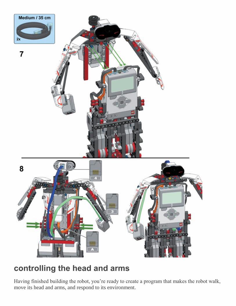
controlling the head and arms
Having finished building the robot, you’re ready to create a program that makes the robot walk,
move its head and arms, and respond to its environment.

You control the movement of the arms and the head with the Medium Motor: Turning the motor
forward makes the head and the arms move to the right; turning the motor backward makes
them move to the left.
my block #5: head
To make it easier to control the movement of the head and arms, you’ll create a My Block and
place it parallel to the main walking program.
The Head My Block first places the Medium Motor in a known position by rotating the head all
the way to the right. Then, it continuously makes the head move left and right, as shown
in Figure 19-16. This movement allows the Infrared Sensor to see obstacles to its left and right
in addition to obstacles ahead of it.
avoiding obstacles and responding to handshakes
Now that you’ve made the My Blocks, it’s easy to create programs that make the robot walk
and respond to sensors. For example, you can change the inner Loop block of
the WalkTest program to make the robot walk forward until the Infrared Sensor sees an obstacle
instead of walking forward for 15 seconds.
Figure 19-16. The configuration of the blocks in the Head My Block (left) and the completed My Block (right)
The final program will make the robot walk around while avoiding obstacles and will make it
respond to handshakes. If you shake the robot’s right hand, the robot will stop walking, say
“Hello, good morning,” and then continue walking. If the robot sees an obstacle, it will say
“Detected” and then turn to the left.
RESETTING THE LEGS AND MAKING THE HEAD MOVE

The program begins by placing the legs in opposite positions with the Reset My Block. Then, it
runs a loop that makes the robot walk and respond to sensors.
As the robot walks, it moves its head left and right using the Head My Block attached to its own
Start block (see Figure 19-17). This configuration makes it possible to control the head and the
legs independently: You can change the behavior of either sequence of blocks without worrying
about interfering with the other sequence. You can change the behavior of the head by
modifying the Head My Block, and you can change the walking behavior by changing the
blocks in the Loop block.
Create a new program called ObstacleAvoid, and add the blocks shown in Figure 19-17.
WALKING UNTIL ONE OF TWO SENSORS IS TRIGGERED
Now you’ll add blocks to the main loop that make the robot walk forward until it sees an
obstacle or detects a handshake (see Figure 19-18).
The robot walks forward by moving the Large Motors forward with the OnSync My Block. The
block is placed in a loop so that the motor speed continuously adjusts to keep the motors
synchronized. The loop runs until the Infrared Sensor is triggered (it detects an obstacle), until
the Color Sensor is triggered (it detects a handshake), or until both sensors are triggered
simultaneously.
Figure 19-17. Step 1: These blocks place the legs in opposite positions and make the robot’s head move. Note that the Loop block inside the Head My Block runs indefinitely so that the head keeps moving left and right.

The Color Sensor block is able to detect a handshake by comparing the Reflected Light
Intensity to a threshold. If the sensor value is greater than 10%, the robot sees your hand and the
output is true. If the value is 10% or less, the sensor doesn’t detect your hand and the output
is false. Similarly, the Infrared Sensor block is configured to output true if a proximity
measurement less than 50% is detected; otherwise, it outputs false.
A Logic Operations block compares both logic values. The output is true if at least one input
value is true, causing the loop to end.
RESPONDING TO THE TRIGGERED SENSOR
The robot is now ready to respond to the sensor that was triggered. If the Infrared Sensor was
triggered, you’ll make the robot say “Detected” and turn to the left. If the Color Sensor was
triggered, you’ll make the robot temporarily stop walking and say “Hello, good morning.”
After the loop completes, you can determine which sensor caused the loop to end by looking at
the output value of the Infrared Sensor block: It’s true if the Infrared Sensor was triggered, and
when it’s false it means that the Color Sensor was triggered. (Because the loop has ended
somehow and the Infrared Sensor wasn’t triggered, you know that the Color Sensor must have
been triggered.)
Use a Switch block to decide which blocks to run based on this value, as shown in Figure 19-
19.
Even though it’s unlikely, the loop may also have ended because both sensors were triggered at
the same time so that the outputs of both Sensor blocks are true. Because the output of the
Infrared Sensor is true, the program simply runs the blocks at the top of the switch, which are
the same blocks that would run if only the Infrared Sensor was triggered. In other words, the
program ignores the Color Sensor in this case.
Add the blocks to the switch that make the robot say “Detected” and turn to the left for true, and
that make the robot say “Hello, good morning” for false (see Figure 19-20).
Now run the program and test it. If you use a USB cable to program the robot, you need to
manually position the head straight forward to make room for the USB cable. To do this, turn
the gears attached to the Medium Motor. Use the Download button to send the program to your
robot, unplug the USB cable, and then start the program manually using the EV3 buttons.
The robot should now walk around autonomously and greet you if you shake its hand.

Figure 19-18. Step 2: The inner loop makes the robot walk forward until the robot detects an obstacle or a
handshake.
Figure 19-19. Step 3: The Switch block determines which sensor triggered the loop to end. If the Infrared Sensor
was triggered, the blocks at the top of the switch will run (true); if it wasn’t, the blocks at the bottom of the switch will run (false).
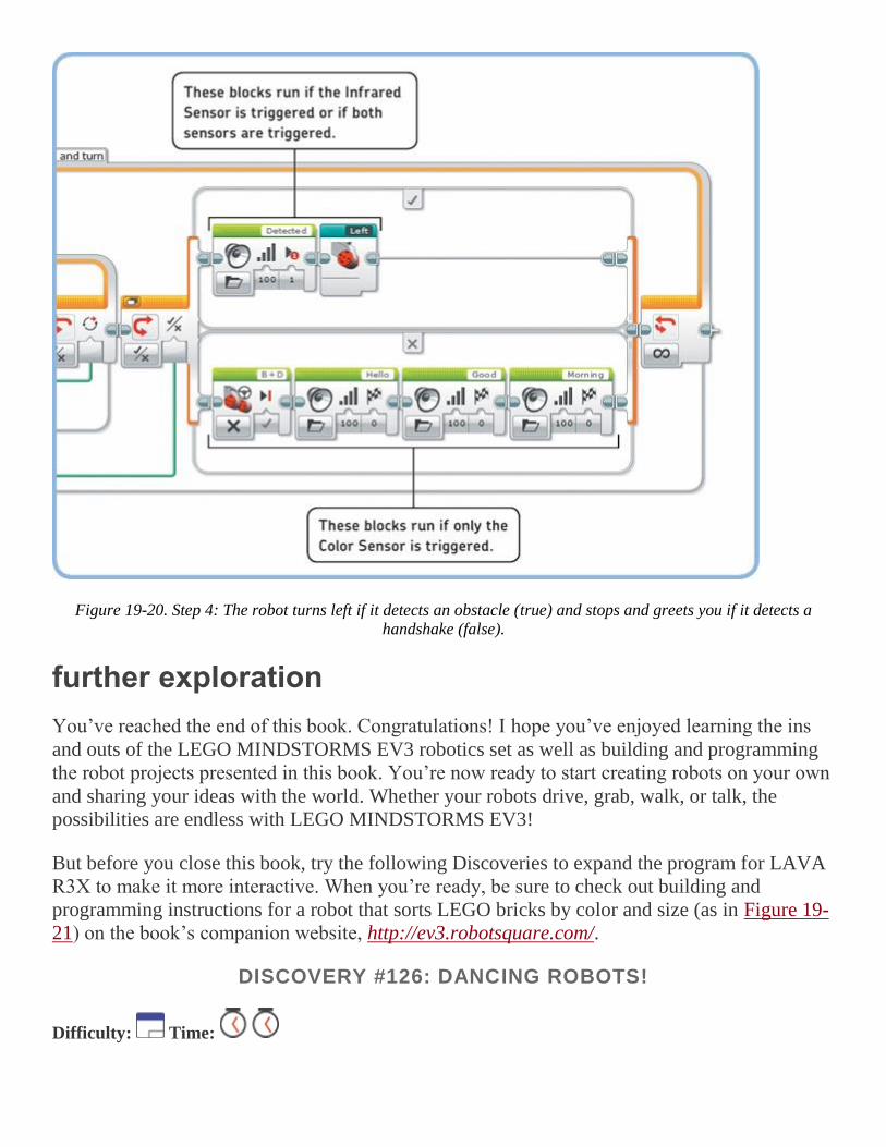
Figure 19-20. Step 4: The robot turns left if it detects an obstacle (true) and stops and greets you if it detects a handshake (false).
further exploration
You’ve reached the end of this book. Congratulations! I hope you’ve enjoyed learning the ins
and outs of the LEGO MINDSTORMS EV3 robotics set as well as building and programming
the robot projects presented in this book. You’re now ready to start creating robots on your own
and sharing your ideas with the world. Whether your robots drive, grab, walk, or talk, the
possibilities are endless with LEGO MINDSTORMS EV3!
But before you close this book, try the following Discoveries to expand the program for LAVA
R3X to make it more interactive. When you’re ready, be sure to check out building and
programming instructions for a robot that sorts LEGO bricks by color and size (as in Figure 19-
21) on the book’s companion website, http://ev3.robotsquare.com/.
DISCOVERY #126: DANCING ROBOTS!
Difficulty: Time:

LAVA R3X is able to walk by placing the leg mechanisms in opposite positions and running both motors
forward. What happens if you place the legs in the same position and then turn both motors at 10% speed
for five rotations but in opposite directions? (You don’t have to worry about motor synchronization in this
Discovery.)
HINT
Once you’ve placed the legs in opposite positions with the Reset My Block, you can easily place the legs in
the same position by rotating one motor forward. How many degrees should you rotate it?
Figure 19-21. Feel like building another robot? The BRICK SORT3R sorts LEGO bricks by color (red, yellow,
green, and blue) and size (2×2 and 2×4). You can find building and programming instructions at the book’s
companion website.
DISCOVERY #127: WHAT’S THE DIFFERENCE?
Difficulty: Time:
To get a better understanding of the OnSync My Block, display the difference between the two motor
positions on the screen. To accomplish this, place a Display block in the OnSync My Block that displays
the value of the last Math block of Figure 19-9. Then place the modified OnSync My Block in a loop
configured to run forever. What happens to the difference if you slow one motor down manually by holding
the leg still? How does the other motor try to compensate for the difference? (Don’t try this for more than a
few seconds!)
DISCOVERY #128: ROBOT COACH!
Difficulty: Time:

Can you make the robot detect how long you work at your desk? Program LAVA R3X to display the
amount of time you’ve been working at your desk, and make it advise you to take a break after one hour. If
it detects that you’re not following the advice, make it shake its head and play sounds to get your attention.
DISCOVERY #129: ROBOT FOLLOWER!
Difficulty: Time:
Can you program the robot look at you as it walks by making its head turn in the direction of the infrared
beacon? Make the speed of the Medium Motor proportional to the Beacon Heading value using a technique
similar to the one you used for the SNATCH3R in Figure 18-20. Note that the robot’s head cannot make a
full turn. How do you limit the motor’s movement in your program so that it doesn’t try to turn farther than
it actually can?
DISCOVERY #130: SYNCHRONIZED PACE!
Difficulty: Time:
In the ObstacleAvoid program, LAVA R3X’s arms move left and right, independent of the pace at which
the robot walks. Can you synchronize both movements so that it walks in a more elegant and realistic way?
DISCOVERY #131: REMOTE WALK!
Difficulty: Time:
Can you make a program that allows you to control LAVA R3X remotely so that it can walk in any
direction? You can use the techniques you learned in Chapter 8, but you’ll need to use the techniques you
learned in this chapter to ensure that the motors in the robot’s legs remain synchronized. How do you make
the robot begin to walk or turn when you press a button on the remote and stop when you release it?
DISCOVERY #132: TAMAGOTCHI!
Difficulty: Time:
Can you turn LAVA R3X into a lifelike robot with different moods and behaviors? Use the infrared remote
to command the robot to walk, talk, eat, and sleep. Create Numeric variables to keep track of the robot’s
health by monitoring its hunger level, energy level, and happiness.
Make the energy level decrease with each step the robot takes, and make it increase when you command
the robot to sleep. Similarly, make the hunger level increase while the robot is walking, and make it
decrease when you feed the robot. Make the robot’s happiness slowly decrease over time, and make it
increase each time you shake the robot’s hand.
If the hunger level, energy level, or happiness reaches a certain critical limit, the robot should ignore new
commands and make its own decisions. For example, if the robot is too tired (its energy level is below
10%), it should fall asleep for a while to restore its energy level. Or, if it’s sad, you can make it say “No!”
and cry each time you try to send new commands.
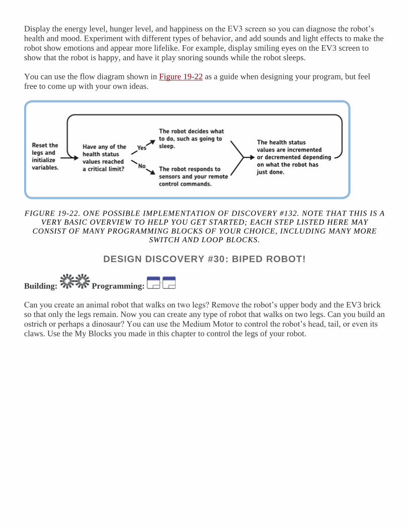
Display the energy level, hunger level, and happiness on the EV3 screen so you can diagnose the robot’s
health and mood. Experiment with different types of behavior, and add sounds and light effects to make the
robot show emotions and appear more lifelike. For example, display smiling eyes on the EV3 screen to
show that the robot is happy, and have it play snoring sounds while the robot sleeps.
You can use the flow diagram shown in Figure 19-22 as a guide when designing your program, but feel
free to come up with your own ideas.
FIGURE 19-22. ONE POSSIBLE IMPLEMENTATION OF DISCOVERY #132. NOTE THAT THIS IS A
VERY BASIC OVERVIEW TO HELP YOU GET STARTED; EACH STEP LISTED HERE MAY
CONSIST OF MANY PROGRAMMING BLOCKS OF YOUR CHOICE, INCLUDING MANY MORE SWITCH AND LOOP BLOCKS.
DESIGN DISCOVERY #30: BIPED ROBOT!
Building: Programming:
Can you create an animal robot that walks on two legs? Remove the robot’s upper body and the EV3 brick
so that only the legs remain. Now you can create any type of robot that walks on two legs. Can you build an
ostrich or perhaps a dinosaur? You can use the Medium Motor to control the robot’s head, tail, or even its
claws. Use the My Blocks you made in this chapter to control the legs of your robot.