Embed Size (px)
Citation preview
CHAPTER 18 REFLECTIVE AND CATADIOPTRIC OBJECTIVES
Lloyd Jones Optical Sciences Center Uni y ersity of Arizona Tucson , Arizona
1 8 . 1 GLOSSARY
A 4th-order aspheric deformation coef ficient
AN 4th-order nonsymmetric deformation coef ficient
B 6th-order aspheric deformation coef ficient
C 8th-order aspheric deformation coef ficient
c surface base curvature
CON conic constant
D 10th-order aspheric deformation coef ficient
FN focal ratio
GLA glass type
h radial surface height
INF infinite radius of curvature
k conic constant
n index of refraction
R radius of curvature
RDX radius of curvature in the x dimension
RDY radius of curvature in the y dimension
STO stop surface
SUR surface number
t element thickness
THI thickness of element or distance to next surface or element
Z surface sag
18 .1

18 .2 OPTICAL INSTRUMENTS
1 8 . 2 INTRODUCTION
During the initial stages of an optical design , many optical engineers take advantage of existing configurations that exhibit useful properties . This chapter is a compilation of reflective and catadioptric objective designs that should help inform the reader of available choices and provide reasonable starting solutions .
The chapter also includes a cursory introduction to some of the more important topics in system analysis , such as angular and linear blur size , image irradiance , scaling , and stray light control .
An extensive list of referenced reading material and brief definitions of terms italicized throughout the text are included .
1 8 . 3 GLASS VARIETIES
Glasses used in the designs are represented in terms of index of refraction and Abbe number or V number , below . The V number indicates glass dispersion . Most glasses can be obtained from a number of vendors .
Glass Index of refraction V -number
BK7 F2 F9 FK51 FN11 Germanium LLF1 LAK21 PSK2 Silica Silicon Sapphire SK1 SK2 SK3 SK16 SF5 SF10 UBK7
1 . 516 1 . 620 1 . 620 1 . 487 1 . 621 4 . 037 1 . 548 1 . 640 1 . 569 1 . 445 3 . 434 1 . 735 1 . 610 1 . 607 1 . 609 1 . 620 1 . 673 1 . 728 1 . 517
64 . 2 36 . 3 38 . 1 84 . 5 36 . 2
117 . 4 45 . 8 60 . 1 63 . 2 27 . 7
147 . 4 15 . 5 56 . 5 56 . 8 58 . 9 60 . 3 32 . 1 28 . 5 64 . 3
1 8 . 4 INTRODUCTION TO CATADIOPTRIC AND REFLECTIVE OBJECTIVES
The variety of objectives presented in this chapter is large . Most of the intricate detail relating to each design is therefore presented with the design itself . In the following paragraphs , analysis of the general features of the catadioptric and reflective objectives is undertaken .
Conic Mirrors It is apparent after a brief perusal of the designs that there are many surface types . Among these are the sphere , paraboloid , hyperboloid , prolate ellipsoid , and oblate ellipsoid . The

REFLECTIVE AND CATADIOPTRIC OBJECTIVES 18 .3
FIGURE 1 Relative shapes of conic surfaces in two dimensions .
oblate ellipsoid is a prolate ellipsoid turned on its side . The equation of a conic is given by the expression
Z 5 ch 2
1 1 4 1 2 (1 1 k ) c 2 h 2 (1)
where Z is the surface sag , k is the conic constant , C is the surface base curvature , and h is the radial height on the surface . The relative shapes of these surfaces are illustrated in Fig . 1 .
Conic mirrors give perfect geometric imagery when an axial point object is located at one conic focus and the axial point image is located at the other conic focus . Figure 2 illustrates these ray paths .
General Aspheres
General aspheres are surfaces with fourth- and higher-order surface deformation on top of a flat or curved surface (see Schulz , 1988) . The surface deformation of a rotationally symmetric general asphere is given by the relation
Z 5 ch 2
1 1 4 1 2 (1 1 k ) c 2 h 2 1 Ah 4 1 Bh 6 1 Ch 8 1 Dh 1 0 (2)
where A , B , C , and D are 4th- , 6th- , 8th- , and 10th-order coef ficients that determine the sign and magnitude of the deformation produced by that order . Although general aspheres allow correction of third - and higher - order aberrations and may reduce the number of elements in an optical system , general aspheres are more expensive than spheres or conics . If aspheric deformation is required , conic surfaces should be tried first , especially since a conic of fers higher-order correction (Smith , 1992) .

18 .4 OPTICAL INSTRUMENTS
FIGURE 2 Ray paths for perfect axial imagery .
Obscurations
Obscurations that block portions of the entering beam reduce image irradiance and image contrast (Smith , 1990 , Everhart , 1959) in reflective and catadioptric systems . Several methods are used to reduce or eliminate completely the ef fects of an obscuration (see Fig . 3) .
Figure 3 a illustrates a commonly employed technique for reducing large-mirror
FIGURE 3 Reducing the size of or eliminating an obscuration .

REFLECTIVE AND CATADIOPTRIC OBJECTIVES 18 .5
obscuration : a small secondary mirror close to the intermediate image moves the larger tertiary mirror out of the beam path .
Figure 3 b is an illustration of an eccentric pupil system . All elements are symmetric about the same axis and the aperture stop is decentered for a clear light path .
Figure 3 c is an example of an of f-axis objective with the field of view biased to direct the center of view away from any intervening elements . All elements and apertures are symmetric about the optical axis .
Figure 3 d is an illustration of a tilted and decentered-component objective . Each element is rotationally symmetric about its own unique optical axis which may be tilted and / or decentered . The imaging behavior of this system is more complicated to deal with than the imaging behavior of eccentric pupil and of f-axis systems . Vector aberration theory (Thompson , 1980 , Sasian , 1990a) has been developed to properly model the imaging behavior of these systems .
Stray Light Suppression
Suppression of light dif fracted from apertures and obscurations is facilitated with intermediate images and a real and accessible Lyot stop . Figure 4 a illustrates a generic refractive configuration with an intermediate image and Lyot stop . Figure 4 b illustrates where the dif fracted light (shaded region) originates and terminates (at one edge of each aperture , for clarity) .
A field stop is placed at the focus of the first lens to block dif fracted light produced by the front light baf fle . To block unwanted objects within the field of view , an occulting disc may be inserted at the focus of the first lens , as is done with a Lyot coronagraph in order to block the sun . By oversizing the field stop slightly , the light dif fracted at the field stop falls just outside of the detector area .
Following the field stop is a second lens that reimages the intermediate image to the final image and the entrance pupil to the Lyot stop (the shaded region in Fig . 4 a illustrates how the entrance pupil is imaged) . Undersizing the Lyot stop blocks the light dif fracted at the entrance pupil . In this way the Lyot stop becomes the aperture stop of the system .
Another application of the Lyot stop in the infrared (assuming the Lyot stop is located
FIGURE 4 Generic objectives with apertures .

18 .6 OPTICAL INSTRUMENTS
exterior to the objective optics) is as a cold stop (Fischer , 1992) . The cold stop (Fig . 4 a ) is a baf fle that prevents stray infrared light , radiated from the housing , from impinging upon the detector from outside its intended field .
Reflective and Catadioptric Objective Designs
The objectives to follow are listed according to focal ratio and design type . Objectives have a 20-cm diameter and catadioptric systems are optimized for a wavelength range from 480 to 680 nm unless otherwise stated . The angles of surface and element tilts are with respect to the horizontal optical axis . Decenters are also with respect to the optical axis . Since many of the designs are aplanatic , anastigmatic , and free of chromatic aberrations , the position of the stop does not af fect third-order aberration correction and may be chosen to minimize y ignetting , distortion , element size , or stray light contamination . All aberrations mentioned in this section are third-order unless otherwise stated .
Definitions of the abbreviated terminology used in the lens data are as follows :
SUR Surface number . RDY Surface radius of curvature . A positive value means the center of curvature lies to the right of the surface ; negative to the left . THI Thickness of element or distance to next element . The value is positive if the next surface lies to the right of the surface . GLA Glass-type or mirror surface , the latter referred to by the abbreviation REFL . CON Conic constant k .
STO Stop surface . INF A surface with an infinite radius of curvature ; that is , a flat surface . A , B , C , D The 4th- , 6th- , 8th- , and 10th-order aspheric deformation coef ficients in Eq . (2) .
A potential source of confusion is the terminology used to describe Mangin elements ; that is , refractive elements with reflective back surfaces . This is illustrated in design 2 (F / 4 Mangin) : a ray enters the second refractive surface of the element (surface 2) and travels to the right where it intersects the mirror surface (surface 3) . The thickness of surface 2 is therefore positive . The ray is reflected by the mirror surface (surface 3) and travels back through the glass element to surface 2 ; hence , the notation F9 / REFL and the negative surface 3 thickness . Since surface 2 and 4 represent the same surface , the radii are the same .
1 . F / 4 Paraboloid Objecti y e
( a ) Newtonian ; ( b ) Herschelian ; ( c ) Pfund .
Comments : A single parabolic mirror objective can be arranged in a variety of forms , the

REFLECTIVE AND CATADIOPTRIC OBJECTIVES 18 .7
best known being the Newtonian . Here a mirror flat diverts the image away from the light path . A tipped-mirror configuration is the Herschelian ; a modern version is untipped and employs an eccentric-pupil to give an accessible image . A ‘‘backwards’’ Newtonian , the Pfund has a large flat-mirror primary . The Pfund has a smaller obscuration than the Newtonian and requires no dif fraction-inducing support structure for the folding flat .
As has been mentioned , the on-axis performance of a paraboloid objective is perfect . Of f-axis , coma quickly degrades image quality . For objectives slower than F / 11 , the easy-to-fabricate spherical mirror gives the same performance as a paraboloid when dif fraction is also considered .
The paraboloid objective has image quality as good as a Cassegrain (design 3) of equivalent FN and aperture diameter , and is easier to align . The Cassegrain has the advantage of being compact .
2 . F / 4 Mangin
SUR RDY THI GLA
1 : 2 : 3 : 4 : 5 :
2 75 . 15 2 307 . 1 2 123 . 63 2 307 . 1 2 75 . 15
1 . 0 1 . 4
2 1 . 4 2 1 . 0
2 80 . 48
BK7 F9 F9 / REFL BK7
Comments : The Mangin (1876) was invented by a French engineer of the same name to replace dif ficult-to-fabricate paraboloids in light houses . The objective relies upon the overcorrected spherical aberration produced by the negative first surface to cancel the undercorrected spherical aberration produced by the focusing , reflective surface . The chromatic aberration of the Mangin is reduced by achromatizing with two glasses of dif ferent dispersions . Secondary spectrum limits on-axis performance , and coma , one-half that of a spherical mirror , is the primary field-limiting aberration . Kingslake (1978) takes the reader through the design of a Mangin mirror .
Mangin mirrors are susceptible to ghost reflections from the refractive surfaces . Antireflection coatings are usually needed .
In some cases the overcorrected chromatic aberration of a Mangin is used to cancel undercorrected chromatic aberration produced by a refractive element . The Schupmann or medial objective (Schupmann , 1899 , Olsen , 1986) has a positive refractive element with undercorrected chromatic aberration which is annulled by a Mangin element .
3 . F / 4 Cassegrain
SUR RDY THI GLA CON
STO 2 :
2 45 . 72 2 19 . 2
2 16 24 . 035
REFL REFL
2 1 2 3 . 236

18 .8 OPTICAL INSTRUMENTS
Comments : The ubiquitous Cassegrain is predominant in situations where a small field of view , high resolution , compact size , long ef fective focal length , and accessible image are required . The classical Cassegrain is composed of a paraboloid primary and hyperboloid secondary , giving perfect imagery on-axis whenever the primary image coincides with the hyperboloidal focus . Coma and field cur y ature limit of f-axis performance .
Many books discuss the first- and third-order properties of Cassegrain objectives . The Rutten (1988) , Schroeder (1987) , Korsch (1991) , and Smith (1990) texts are among these .
4 . F / 4 Ritchey - Chretien
SUR RDY THI GLA CON
STO 2 :
2 45 . 72 2 19 . 2
2 16 24 . 034
REFL REFL
2 1 . 072 2 3 . 898
Comments : The aplanatic Cassegrain or Ritchey-Chretien (Chretien , 1922) is also corrected for coma , leaving astigmatism and field curvature uncorrected . Both mirrors of the Ritchey-Chretien are hyperboloids .
Numerous modern telescope objectives are of Ritchey-Chretien form ; among these are the Hubble space telescope and the infrared astronomical satellite IRAS .
5 . F / 9 Ritchey - Chretien Telescope with Two - Lens Corrector
SUR RDY THI GLA CON
STO 2 : 3 : 4 : 5 : 6 :
2 2139 . 7 2 802 . 83
67 . 73 90 . 39
2 1925 . 6 129 . 1
2 794 . 0 853 . 96
2 . 54 9 . 9 1 . 27
14 . 39
REFL REFL BK7
BK7
2 1 . 0778 2 4 . 579
Comments : This is a design by Wynne (1965) for the correction of the Cassegrain focus of a large (350-cm) Ritchey-Chretien . The corrector removes the inherent astigmatism and field curvature of the Ritchey-Chretien . Other Cassegrain focus correctors are discussed by Schulte (1966a) , Rosin (1966) , and Wilson (1968) .

REFLECTIVE AND CATADIOPTRIC OBJECTIVES 18 .9
6 . F / 4 Dall - Kirkham
SUR RDY THI GLA CON
STO 2 45 . 72 2 16 REFL 2 0 . 6456
6th order term : 0 . 593E-10
2 : 2 19 . 2 24 . 035 REFL
Comments : The Dall-Kirkham is another Cassegrain corrected for spherical aberration . The primary is an ellipsoid with 6th-order aspheric deformation and the secondary is spherical . An inverse Dall-Kirkham , or Carlisle , is just the reverse , with a spherical primary . There is zonal spherical aberration without the 6th-order deformation . Five times more coma is produced by the Dall-Kirkham than the classical Cassegrain , seriously limiting the field of view .
7 . F / 4 Cassegrain with Field Corrector and Spherical Secondary
SUR RDY THI GLA CON
1 : STO 3 : 4 : 5 : 6 :
2 94 . 21 2 94 . 29
17 . 59 8 . 76
2 64 . 15 2 13 . 41
2 27 . 937 17 . 72
0 . 35 0 . 491 0 . 6
13 . 67
REFL REFL Silica
Silica
2 1
Comments : By adding zero-power refractive correctors , the performance of a reflective objective is substantially enhanced . Zero power is maintained to prevent axial color . Such is the case with this objective similar to one designed by Rosin (1964) . All third-order aberrations , with the exception of distortion , are corrected . The surfaces , with the exception of the primary , are spherical . One of the most attractive features of this design , in comparison to the Schmidt which will be discussed shortly , is the small size of the refractive elements . Add to this the capability of eliminating any remaining spherical aberration in an assembled objective by adjusting the axial positions of the lenses .
Zero Petz y al sum and , hence , a flat image (in the absence of astigmatism) is ensured by giving the mirrors the same curvature and the lens elements equal and opposite power .

18 .10 OPTICAL INSTRUMENTS
8 . F / 15 Spherical - primary Cassegrain with Reflecti y e Field Corrector
SUR RDY THI GLA CON
STO 2 : 3 : 4 :
2 84 . 03 2 46 . 56 2 17 . 39 2 20 . 87
2 30 . 69 36 . 83
2 14 . 77 16 . 26
REFL REFL REFL REFL
20 . 97 2 0 . 8745
2 96 . 62
Comments : This well-corrected design from Korsch (1991) has an easily manufactured spherical primary and is intended for use as a large-aperture telescope objective . Another all-reflective corrector of Gregorian form has been developed for a fast (F / 0 . 6) spherical primary (Meinel , 1984) .
9 . Afocal Cassegrain - Mersenne Telescope
SUR RDY THI GLA CON
STO 2 :
2 100 2 30
2 35 40
REFL REFL
2 1 2 1
Comments : The Mersenne contains two confocal paraboloids working at infinite conjug- ates . It is aplanatic , anastigmatic , and can be made distortion-free by choosing an appropriate stop location . The utility of confocal mirrors has been emphasized by Baker (1978) and Brueggeman (1968) , and is illustrated in the following design .
10 . Dual - magnification Cassegrain
SUR RDY THI GLA CON
STO 2 : 3 : 4 : 5 : 6 : 7 : 8 : 9 :
10 :
2 33 . 99 2 10 . 61
10 . 486 25 . 673 48 . 33 22 . 68 3 . 52 4 . 22
INF INF
2 11 . 69 12 . 76
0 . 877 0 . 462 0 . 798 7 . 57 1 . 0 0 . 377 0 . 16 0 . 396
REFL REFL Silicon
Germanium
Silicon
Sapphire
2 1 2 1
Comments : This IR design is related to one introduced by T . Fjeidsted (1984) . The system of fers two magnifications and fields of view . The high-magnification configuration is

REFLECTIVE AND CATADIOPTRIC OBJECTIVES 18 .11
with the afocal Mersenne in the optical path . Removing the secondary lets light pass directly to the refractive assembly and a larger field of view is observed . The spectral range is from 3 . 3 to 4 . 2 m m .
11 . F / 3 .2 Three - lens Prime Focus Corrector
SUR RDY THI GLA CON
STO 2 : 3 : 4 : 5 : 6 : 7 :
2 1494 . 57 2 26 . 98 2 31 . 3 2 53 . 96 2 19 . 0 2 33 . 36 236 . 7
2 684 . 08 2 2 . 6
2 22 . 43 2 0 . 586
2 28 . 87 2 2 . 042
2 11 . 65
REFL UBK7
UBK7
UBK7
2 1
Comments : This is a three-lens corrector for a 250-cm parabolic mirror . The corrector was developed by Wynne (1965 , 1974) for the region of the spectrum extending from 365 to 1014 nm . It is used to extend the field of a parabolic mirror . Versions for a Ritchey-Chretien primary also exist . The corrector is able to correct spherical aberration , coma , astigmatism , and field curvature while keeping chromatic aberrations under control . The field of view can be extended considerably for smaller apertures .
The three-spherical lens corrector is one of the best large-optics prime-focus correctors to come along , both in terms of image quality and ease of fabrication . Other designs have either not performed as well or were heavily dependent on aspheric figuring .
This and other prime-focus correctors are surveyed in articles by Gascoigne (1973) , Ross (1935) , Meinel (1953) , Schulte (1966b) , Baker (1953) , and Wynne (1972a) .
12 . F / 4 Gregorian
SUR RDY THI GLA CON
STO 2 :
2 24 . 62 6 . 4
2 16 24 . 1
REFL REFL
2 1 2 0 . 5394
Comments : The classical Gregorian is aberration-free on-axis when the paraboloidal mirror image coincides with one of the ellipsoidal-mirror foci ; the other focus coincides with the final image . Like the Cassegrain , of f-axis image quality is limited by coma and field curvature . The ellipsoidal secondary reimages the entrance pupil to a location between the secondary and final image . Thus , there exists the possibility of unwanted-light suppression at the primary-mirror image and exit pupil .
The Gregorian is longer than the Cassegrain and thus more expensive to support and

18 .12 OPTICAL INSTRUMENTS
house , but it produces an erect image and the concave secondary is easier to produce . In eccentric-pupil versions it has an accessible prime focus .
13 . F / 4 Aplanatic Gregorian
SUR RDY THI GLA CON
STO 2 :
2 24 . 62 6 . 4
2 16 24 . 1
REFL REFL
2 0 . 989 2 0 . 5633
Comments : The aplanatic Gregorian is corrected for spherical aberration and coma . Both mirrors are ellipsoids . Astigmatism and field curvature limit of f-axis imagery .
14 . F / 1 .25 Flat - medial - field Aplanatic Gregorian
SUR RDY THI GLA CON
STO 2 :
2 34 . 68 6 . 47
2 22 . 806 7 . 924
REFL REFL
2 0 . 767 2 0 . 1837
Comments : The Gregorian’s field performance is enhanced if image accessibility is sacrificed . This version of the Gregorian (Korsch , 1991) is aplanatic . A flat medial image is achieved by balancing Petzval curvature with astigmatism , which remains uncorrected .
15 . F / 1 .25 Flat - medial - field Aplanatic Gregorian with Spherical Primary
SUR RDY THI GLA CON
STO 2 :
2 42 . 59 INF
2 21 46 . 51
REFL REFL
Tilt : 45 8
3 : 2 49 . 84 2 54 . 08 REFL 2 0 . 078

REFLECTIVE AND CATADIOPTRIC OBJECTIVES 18 .13
Comments : The field of this objective (Korsch , 1991) is larger than its cousins , the classical and aplanatic Gregorians , even with the spherical primary . Spherical aberration and coma are corrected , and the medial image is flat . The design has a real intermediate image and exit pupil . The obvious drawback is the size of the secondary in relation to the size of the entrance pupil , which is 15 cm in diameter .
Korsch (1991) analyzes two other designs that are loosely referred to as Gregorians .
16 . Afocal Gregorian - Mersenne Telescope
SUR RDY THI GLA CON
STO 2 :
2 50 10
2 30 40
REFL REFL
2 1 2 1
Comments : The Gregorian Mersenne , also composed of confocal paraboloids , is ap- lanatic , anastigmatic , and can be corrected for distortion . The Gregorian-Mersenne has an intermediate image and an accessible exit pupil .
17 . F / 1 .25 Couder
SUR RDY THI GLA CON
STO 2 :
2 142 . 86 23 . 08
2 52 . 9 7 . 1142
REFL REFL
2 6 . 285 2 0 . 707
Comments : The Couder (1926) , composed of two conic mirrors , is corrected for third-order spherical aberration , coma , and astigmatism . Unfortunately , the Couder is long for its focal length and the image is not readily accessible .
18 . F / 1 .25 Aplanatic , Flat - medial - image Schwarzschild
SUR RDY THI GLA CON
STO 2 :
2 91 . 57 23 . 67
2 38 . 17 4 . 637
REFL REFL
2 2 . 156 5 . 256
Comments : The aplanatic , flat-medial-image Schwarzschild (1905) is similar in ap- pearance to the Couder but the secondary mirror and image locations are dif ferent for identical secondary magnifications .

18 .14 OPTICAL INSTRUMENTS
19 . F / 1 .25 Aplanatic , Anastigmatic Schwarzschild
SUR RDY THI GLA
1 : 2 : STO
30 . 62 80 . 14 INF
2 49 . 44 80 . 26 24 . 864
REFL REFL
Comments : The spherical-mirror Schwarzschild (1905) is aplanatic , anastigmatic , and distortion-free (Abel , 1980) . The Schwarzschild relies on the principle of symmetry for its high level of aberration correction and a large field of view . All surfaces have the same center of curvature at the aperture stop . Hence , there are no of f-axis aberrations . Spherical aberration is produced but each mirror produces an equal and opposite amount , thus canceling the ef fect of the aberration . Some higher-order aberrations are also corrected (Abel , 1980) . Eccentric portions of this design—above and below the optical axis in the picture—form well-corrected , unobscured designs . Zonal spherical aberration from the mix of third- and higher-order terms limits on- and of f-axis performance .
An aspheric plate positioned at the center-of-curvature of the mirrors removes this aberration as illustrated in the next design .
Wetherell and Rimmer (1972) , Korsch (1991) , Schroeder (1987) , Linfoot (1955) , and Gascoigne (1973) of fer a general third-order analysis of two-mirror systems . The closed-form solutions described provide insight into third-order aberration theory of reflective systems .
20 . F / 1 Aplanatic , Anastigmatic Schwarzschild with Aspheric Corrector Plate
SUR RDY THI GLA
1 : 2 : STO
24 . 547 63 . 92 INF
2 39 . 456 64 . 528
2 19 . 098
REFL REFL REFL
A : 2 0 . 9998E-7 B : 2 0 . 1269E-9
Comments : With an aspheric plate at the aperture stop , spherical aberration is elimin- ated . The only aberrations still remaining are of higher order . To correct these , the mirrors must also be aspherized . Linfoot (1955) and Abel (1980) describe this design .

REFLECTIVE AND CATADIOPTRIC OBJECTIVES 18 .15
21 . F / 1 .25 Anastigmatic , Flat - image Schwarzschild
SUR RDY THI GLA CON
1 : STO
69 . 7 71 . 35
2 50 . 56 61 . 26
REFL REFL
5 . 47 0 . 171
Comments : With just two conics , this design type (Schwarzschild , 1905) achieves aplanatic and anastigmatic performance on a flat image surface . The flat field is attained by making the curvatures of the mirrors equal . Eccentric portions above or below the optical axis form unobscured versions ; the design may alternatively be used of f-axis . Sasian (1990a , 1990b) and Shafer (1988) have explored many of this design’s features .
22 . F / 1 .25 Schmidt
SUR RDY THI GLA CON
STO 1554 1 PSK2
A : 2 0 . 2825E-5 B : 2 0 . 1716E-8
2 : 3 :
INF 2 52 . 95
52 . 33 2 26 . 215 REFL
Comments : The Schmidt (1932) also relies on the principle of symmetry ; that is , the aperture stop is located at the center of curvature of the spherical mirror and hence the mirror produces no of f-axis aberrations .
The Schmidt corrector is flat with aspheric deformation figured in to correct the spherical aberration produced by the mirror . It is positioned at the aperture stop because of f-axis aberrations are independent of aspheric deformation when an aspheric surface coincides with the stop . Hence the Schmidt plate has no ef fect on of f-axis aberrations , and the benefits of concentricity are preserved .
The corrector introduces chromatic variation of spherical aberration (spherochromat- ism) . A small amount of positive power in the corrector introduces undercorrected axial color to reduce the ef fects of this aberration . Further improvement is obtained by achromatizing the corrector with two glasses of dif ferent dispersions .
Higher-order aberrations degrade image quality at low focal ratios and large field

18 .16 OPTICAL INSTRUMENTS
angles . Kingslake (1978) , Schroeder (1987) , Maxwell (1972) , and Linfoot (1955) provide additional details of this and other catadioptric objectives .
23 . F / 1 .25 Field - flattened Schmidt
SUR RDY THI GLA
STO 598 . 7 1 . 155 PSK2
A : 2 0 . 273E-5 B : 2 0 . 129E-8
2 : 3 : 4 : 5 :
INF 2 52 . 95 2 10 . 35 INF
40 . 38 2 24 . 06 2 1 . 49 2 0 . 637
REFL PSK2
Comments : As is known from third-order aberration theory , a thin element will be nearly aberration-free , except for Petzval curvature , and distortion when it is placed in close proximity to an image . Therefore , by properly choosing the lens power and index to give a Petzval curvature of equal and opposite sign to the Petzval curvature introduced by the other optics , the image is flattened .
The image in the Schmidt above has been flattened with the lens near the image plane . The only aberrations introduced by the lens are spherochromatism and lateral color , lateral color being the most noticeable aberration ; this can be removed by achromatizing the field-flattening lens . The close proximity of the lens to the image can cause problems with light scattered from areas on the lens surfaces contaminated by dirt and dust particles . Clean optics are a must under these circumstances .
The field-flattening lens provides two more positive results . First , the lens introduces a small amount of coma which is compensated by moving the Schmidt corrector towards the mirror somewhat , thus reducing the overall length of the objective . Second , oblique spherical aberration , one of the primary field-limiting , higher-order aberrations of the Schmidt , is substantially reduced .
Besides its usual function as a telescope or photographic objective , the field-flattened Schmidt has also been used as a spectrograph camera (Wynne , 1977) .
24 . F / 1 .25 Wright
SUR RDY THI GLA CON
1 : 2 :
INF 2 699 . 8
1 . 0 26 . 1
BK7
A : 0 . 6168E-5 B : 0 . 5287E-8
3 : 2 53 . 24 2 26 . 094 REFL 1 . 026
Comments : The Wright (1935) is one-half the length of the Schmidt . It also relies on
REFLECTIVE AND CATADIOPTRIC OBJECTIVES 18 .17
aspheric deformation of the corrector plate for the elimination of spherical aberration . Coma , introduced as the corrector is removed from the center of curvature of the mirror , is cancelled with conic deformation of the mirror ; the surface figure is that of an oblate ellipsoid . The remaining astigmatism and Petzval curvature are balanced for a flat medial image . The only on-axis aberration , spherochromatism , is corrected by achromatizing the corrector .
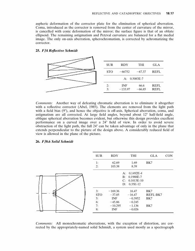
25 . F / 4 Reflecti y e Schmidt
SUR RDY THI GLA
STO 2 66752 2 67 . 37 REFL
A : 0 . 5083E-7
2 : 3 :
INF 2 133 . 97
66 . 6 2 66 . 85
REFL REFL
Comments : Another way of defeating chromatic aberration is to eliminate it altogether with a reflective corrector (Abel , 1985) . The elements are removed from the light path with a field bias (9 8 ) , and hence the objective is of f-axis . Spherical aberration , coma , and astigmatism are all corrected . At large field angles , beyond about 12 8 half-field angle , oblique spherical aberration becomes evident , but otherwise this design provides excellent performance on a curved image over a 24 8 field of view . In order to avoid severe obstruction of the light path , the full 24 8 can be taken advantage of only in the plane that extends perpendicular to the picture of the design above . A considerably reduced field of view is allowed in the plane of the picture .
26 . F / 0 .6 Solid Schmidt
SUR RDY THI GLA CON
1 : 2 :
62 . 69 103 . 38
1 . 69 8 . 39
BK7
A : 0 . 1492E-4 B : 0 . 1988E-7 C : 0 . 1013E-10 D : 0 . 35E-12
3 : STO 5 : 6 : 7 : 8 :
2 169 . 36 2 37 . 05
INF 2 45 . 86 2 10 . 295
INF
16 . 47 2 16 . 47 2 0 . 3952 2 0 . 245 2 1 . 136 2 0 . 026
BK7 REFL \ BK7 BK7
BK7
Comments : All monochromatic aberrations , with the exception of distortion , are cor- rected by the appropriately-named solid Schmidt , a system used mostly as a spectrograph

18 .18 OPTICAL INSTRUMENTS
camera (Schulte , 1963) . All chromatic aberrations , with the exception of lateral color , are corrected . The imaging theory behind the solid Schmidt is expounded by J . Baker (1940a) . With a refractive index n , the solid Schmidt is n 2 times faster than the conventional Schmidt . Focal ratios of F / 0 . 3 have been obtained . Schulte (1963) of fers a design similar to the one given here .
27 . F / 1 .25 Schmidt - Cassegrain
SUR RDY THI GLA CON
STO INF 0 . 8 489 . 574
A : 2 0 . 1928E-4 B : 0 . 298E-7
2 : 3 :
2269 . 1 INF
1 . 0 16 . 49
583 . 303
A : 2 0 . 1085E-4 B : 0 . 2806E-7
4 : 2 55 . 9 2 15 . 0 REFL 1 . 077 5 : 6 : 7 : 8 : 9 :
INF 9 . 1
2 8 . 577 2 8 . 59
2 87 . 44
10 . 267 1 . 2 0 . 018 0 . 3 1 . 317
REFL 489 . 574
583 . 303
Comments : The Schmidt-Cassegrain (Baker , 1940b) represents a successful attempt to resolve the dif ficulties related to the curved image , considerable length , and awkwardly located image of the Schmidt objective , without destroying the positive attributes of the design .
The Schmidt-Cassegrain comes in a wide variety of forms—too many to go into here . Linfoot (1955) performs an extensive exploration of the design , with one and two aspheric plate correctors . Warmisham (1941) has gone as far as three . Wayman (1944) has analyzed a monocentric Schmidt-Cassegrain .
In this fast version of the Schmidt-Cassegrain , the corrector is close to the flat secondary . Usually one or both mirrors are aspherics . An achromatized image-flattening lens has been introduced . An image-flattening lens is not usually required with a Schmidt-Cassegrain since enough degrees of freedom exist for aberration correction and a flat image . In this case , the secondary mirror is flat and one degree of freedom is lost . Additionally , the primary mirror power introduces a strong Petzval contribution which necessitates a field-flattening lens .
The first three digits of the six-digit code in the glass column identify the indices of the materials in the design , in this case plastics . These are 1 . 489 and 1 . 583 ; the Abbe - numbers are given by the last three digits and they are 57 . 4 and 30 . 3 , respectively . The two plastics have nearly identical thermal coef ficients and are very light . Buchroeder (1971a) analyzes designs of this variety with two aspheric correctors . Shafer (1981) of fers a Schmidt- Cassegrain with an aspheric meniscus corrector . Only two elements are used since the secondary mirror surface is on the corrector . Rutten (1988) has examples of Schmidt- Cassegrains in a number of configurations .

REFLECTIVE AND CATADIOPTRIC OBJECTIVES 18 .19
28 . F / 3 .4 Reflecti y e Schmidt - Cassegrain
SUR RDY THI GLA CON
STO INF 2 92 . 16 REFL
A : 0 . 13344E-6 AN : 2 0 . 1255E-1
2 : 3 :
84 84
26 2 25 . 848
REFL REFL 2 0 . 3318
Comments : The reflective Schmidt-Cassegrain exhibits all the nice properties of the Schmidt-Cassegrain and , in addition , is achromatic . Schroeder (1978) points out that , because the corrector is tilted (9 8 here) , adequate aberration correction requires a nonrotationally symmetric corrector plate . The nonaxially symmetric surface deformation in this design is given by
Z 5 A [(1 2 AN ) X 2 1 (1 1 AN ) Y 2 ] 2 (3)
where A is the fourth-order symmetric coef ficient and AN is the fourth-order nonsymmet- ric coef ficient . The y dimension is in the plane of the picture ; the x dimension is perpendicular to it .
Since the corrector is tilted by 9 8 , the reflected rays are deviated by twice that amount . The element spacings (THI) are no longer measured along the horizontal optical axis after reflection of f the corrector , but along the line of deviation . The secondary and tertiary are tilted by 18 8 .
29 . F / 2 Shafer Relayed Virtual Schmidt
SUR RDY THI GLA
STO 2 : 3 :
2 320 106 . 7 INF
2 159 . 82 80 . 0
2 68 . 51
REFL REFL REFL
A : 0 . 1882E-5 B : 0 . 1273E-8 C : 2 0 . 1757E-12 D : 0 . 1766E-14
4 : 63 . 967 40 . 774 REFL
Comments : Shafer (1978a) has introduced an eccentric-pupil (18-cm stop decenter) , virtual Schmidt objective similar to this but with a decentered quaternary mirror . The center of curvature of the spherical primary is imaged by the concave secondary onto the flat Schmidt tertiary mirror . Now the Schmidt plate , which appears to be at the primary center of curvature , is aspherized to produce a well-corrected virtual image , hence the

18 .20 OPTICAL INSTRUMENTS
FIGURE 5 Picture of virtual Schmidt with decen- tered quaternary .
name (see Fig . 5) . In this configuration , the Schmidt plate is one-half the size of the primary .
The Schmidt plate and the spherical quaternary mirror form a finite conjugate Schmidt system . Thus , the spherical aberration of this mirror is also corrected .
Figure 5 shows a pictorial representation of the Shafer design with the last mirror decentered to provide a more accessible image . Since the primary and quaternary mirrors no longer share the same axis of symmetry , a two-axis Schmidt corrector is required to remove the aberrations of both mirrors . The shape of this surface is described by Shafer , for an F / 1 , unobscured , wide-field design with an intermediate image and Lyot stop .
30 . F / 2 .2 Spherical - primary Objecti y e That Employs the Schmidt Principle of Correction
SUR RDY THI GLA CON
STO 2 :
2 88 . 07 INF
2 42 . 51 2 . 2
REFL REFL
Tilt : 45 8
3 : 4 : 5 : 6 : 7 :
2 4 . 433 2 2 . 527
2 10 . 21 2 2 . 527 2 4 . 433
0 . 33 9 . 217
2 9 . 217 2 0 . 33 2 0 . 64
FK51
REFL FK51
2 0 . 8631
Comments : Baker (1978) reports on a system where the center of curvature of a large , spherical primary is imaged by a positive lens onto a much smaller mirror where aspheric correction of spherical aberration occurs . A small field of fset (0 . 25 8 ) is required so that the one-to-one relay doesn’t reimage the primary image back onto itself . To avoid overlap , this design is best used over a small or strip field of view .
Because of the geometry of the design , coma , astigmatism , image curvature , chromatic aberrations , and distortion are eliminated in addition to the spherical aberration correction from aspheric figuring of the tertiary mirror . Baker (1978) of fers several other interesting designs in his article , including an F / 0 . 8 , 10 . 6- m m , 180 8 field-of-view Roesch (1950) , a design that incorporates a Schmidt with a strong negative lens or lens group before the

REFLECTIVE AND CATADIOPTRIC OBJECTIVES 18 .21
aspheric corrector . The strong divergence produced by this lens reduces the amount of light blocked by the image plane but increases the size of the spherical mirror .
31 . F / 2 Maksuto y
SUR RDY THI GLA CON
STO 2 : 3 : 4 :
INF 2 23 . 06 2 25 . 53 2 83 . 9
31 . 788 3 . 5
51 . 09 2 43 . 8
BK7
REFL
Comments : The all-spherical Maksutov (1944) was intended as an inexpensive alternative to the Schmidt at slower speeds . In small sizes it is indeed less expensive . The meniscus corrector is ‘‘self-achromatic’’ when the following relationship is satisfied :
t 5 n 2
n 2 2 1 ( R 2 2 R 1 ) (4)
where R 1 and R 2 are the radii , t is the thickness , and n is the refractive index of the corrector .
Bouwers (1950) also developed a meniscus corrector . All elements of the Bouwers are concentric about the aperture stop . This ensures correction of third-order , of f-axis aberrations over a nearly unlimited field of view . In exchange for the wide field , axial color is not well-corrected .
32 . F / 1 .25 Solid Maksuto y - Cassegrain
SUR RDY THI GLA CON
STO 2 : 3 : 4 : 5 : 6 : 7 : 8 : 9 :
10 : 11 :
INF 2 20 . 5 2 25 . 92 138 . 58
2 45 . 61 2 51 . 89
INF 12 . 026 16 . 07 INF INF
20 . 5 0 . 955 0 . 0313
15 . 3 2 12 . 973
13 . 41 0 . 0475 1 . 68 0 . 545 0 . 394 0 . 155
Silica
Silica REFL \ Silica REFL \ Silica
Silica
Silica
Comments : The solid Maksutov-Cassegrain shown here and the solid Schmidt- Cassegrains have been studied extensively by Wynne (1971 , 1972b) . Lateral color is the most consequential aberration left uncorrected .

18 .22 OPTICAL INSTRUMENTS
33 . F / 1 .2 Wide - field Objecti y e with Maksuto y Correction
SUR RDY THI GLA CON
1 : 2 : 3 : STO 5 :
12 . 467 2 4 . 81 2 3 . 762
INF 15 . 98
2 9 . 684 2 1 . 267 2 3 . 679
2 17 . 189 10 . 64
REFL FK51
REFL
2 3 . 243
Comments : This very wide field imaging system similar to one in Courtes et al . (1971) is essentially a Maksutov focused on the virtual image of the object produced by the hyperboloidal mirror . Both speed (F / 1) and a very wide field of view (80 3 120 degrees) can be achieved with this design form on a flat image but only for small apertures—1 . 25 cm in this case . Courtes (1983) describes similar systems with refractive and reflective Schmidt plates instead of a Maksutov corrector .
34 . F / 1 Gabor
SUR RDY THI GLA
STO 2 : 3 : 4 : 5 : 6 :
2 23 . 3 2 25 . 468 2 83 . 33 2 1 . 67
9 . 85 2 7 . 71
2 39 . 5
2 40 2 1 2 0 . 5 2 0 . 942
SK1
REFL BK7 SF5
Comments : Another meniscus design was invented by Gabor (1941) . The Gabor is more compact than the Maksutov or Bouwers , and has a smaller focal ratio and field of view .
The design shown here began without the field lens . The lens was introduced into the design with the surface closest to the image being concentric about the chief ray and the other surface being aplanatic (Welford , 1986) . A surface concentric about the chief ray is free of coma , astigmatism , distortion , and lateral color . The aplanatic surface is free of spherical aberration , coma , and astigmatism with the result that the lens is coma- and astigmatism-free . The spherical aberration produced by the lens is balanced against the spherical aberration produced by the two other elements . The chromatic aberrations were corrected by achromatizing the lens .
Shafer (1980a , 1980b) of fers interesting suggestions for design with aplanatic and

REFLECTIVE AND CATADIOPTRIC OBJECTIVES 18 .23
concentric surfaces . Several varieties of field-flattening lens are described . Kingslake (1978) runs through the design procedure for a Gabor .
35 . F / 4 Schmidt - meniscus Cassegrain
SUR RDY THI GLA
STO 2 : 3 : 4 : 5 : 6 :
787 . 7 INF
2 32 . 69 2 35 . 6 2 81 . 97 2 79 . 5
1 . 4 32 . 69 2 . 62
63 . 446 2 21 . 78
38 . 65
BK7
BK7
REFL REFL
Comments : This system , originally by Bouwers , uses a slightly positive plate to compensate the overcorrected chromatic aberration produced by the meniscus . The Bouwers produces very good quality on a flat image , over a large field of view .
Fourth- and sixth-order deformation added to the plate eliminates any residual spherical aberration . Lateral color and oblique spherical aberration af fect field perfor- mance , although both are small .
36 . F / 1 .2 Baker Super - Schmidt
SUR RDY THI GLA
1 : 2 :
STO
22 . 5 19 . 13
2 11 , 783
4 . 28 19 . 75 1 . 4
BK7
F2
A : 2 0 . 558E-6 B : 0 . 244E-8
4 : 5 : 6 : 7 : 8 : 9 :
10 :
2 135 . 5 INF
2 29 . 31 2 32 . 42 2 55 2 32 . 42 2 29 . 31
1 . 3 23 . 92 4 . 28
25 . 1 2 25 . 1 2 4 . 28 2 1 . 45
SK2
BK7
REFL BK7
Comments : The Baker (1945) super-Schmidt , a design that incorporates both meniscus and Schmidt correction , achieves excellent performance over a wide field of view . The field-limiting aberration of a fast Schmidt , oblique spherical aberration , is controlled by adding a concentric meniscus lens which also introduces overcorrected spherical aberra- tion , thus reducing the amount of overcorrection needed from the Schmidt plate . Since oblique spherical is proportional to the amount of overcorrection in the Schmidt plate , the ef fect of this aberration is reduced .
The most apparent aberration produced by the meniscus is axial color . This is minimized by achromatizing the Schmidt corrector . Spherochromatism is reduced since

18 .24 OPTICAL INSTRUMENTS
the magnitudes produced by the Schmidt corrector and meniscus are nearly equal and have opposite signs . Another meniscus element is added to further reduce aberrations .
37 . F / 1 Baker - Nunn
SUR RDY THI GLA
1 : 2 :
2 491 . 9 2 115 . 6
1 . 06 4 . 23
LLF1
A : 2 0 . 8243E-5 B : 0 . 1348E-8
STO 2 125 . 78 0 . 64 SK3
A : 2 0 . 1158E-4 B : 2 0 . 427E-8 C : 2 0 . 7304E-11
4 : 125 . 78 4 . 23
A : 0 . 1158E-4 B : 0 . 427E-8 C : 0 . 7304E-11
5 : 115 . 6 1 . 06 LLF1
A : 0 . 8243E-5 B : 2 0 . 1348E-8
6 : 7 :
491 . 87 2 42 . 03
36 . 77 2 21 . 961 REFL
Comments : The Baker-Nunn (Baker , 1962) was born of work by Houghton (1944) during World War II . Houghton wished to find a less expensive alternative to the Schmidt . The result was a zero-power , three-lens combination with easy-to-make spherical surfaces . Spherical aberration and coma can be eliminated for any position of the corrector . The surfaces have equal radii so they can be tested interferometrically against one another using the Newton ring method . Residual spherical aberration that remains after assembly is removed by altering the spacing between the lenses .
38 . F / 10 Houghton - Cassegrain
SUR RDY THI GLA
STO : 2 : 3 : 4 : 5 : 6 :
145 2 172 . 1 2 111 . 9
264 . 7 2 129 . 7 2 63 . 94
1 . 2 0 . 164 0 . 639
44 . 61 2 43 . 16
66 . 84
BK7
BK7
REFL REFL

REFLECTIVE AND CATADIOPTRIC OBJECTIVES 18 .25
Comments : A two-lens , afocal corrector developed by Houghton and Sonnefeld (1938) is used here as a corrector for a Cassegrain system . Sigler (1978) has written on the subject of Cassegrains with Houghton , Schmidt , and Maksutov refractive correctors . This Houghton- Cassegrain gives well-corrected imagery on a curved image surface . An afocal ach- romatized doublet corrector has also been tried (Hawkins and Linfoot , 1945) .
39 . F / 3 .6 Houghton - Cassegrain
SUR RDY THI GLA
STO 2 : 3 : 4 : 5 : 6 : 7 : 8 : 9 :
10 :
69 . 64 148 . 71
2 61 . 43 2 97 . 53 2 85 . 11 2 97 . 53
70 . 44 2 15 . 47 2 15 . 23
2 517 . 29
1 . 607 3 . 045 1 . 607
21 . 733 2 21 . 733
21 . 733 1 . 2 0 . 18 1 . 3136
11 . 03
UBK7
LAK21
REFL REFL UBK7
SK16
Comments : Another Houghton corrector , with meniscus elements , is utilized in this design by D . Rao (1987) . The spectral range is 550 to 850 nm . The design is similar to one introduced by Mandler (1951) . Examples of other Houghton-Cassegrains of this form are studied by Gelles (1963) .
40 . F / 1 .25 Shenker
SUR RDY THI GLA
STO 2 :
49 . 42 2 203 . 6
1 . 5 5 . 4
BK7
3 : 4 : 5 : 6 : 7 : 8 : 9 :
10 : 11 : 12 :
2 34 . 7 2 79 . 25 2 27 2 38 . 87 2 31 . 96 2 38 . 87
13 . 73 21 . 8 7 . 925 8 . 56
0 . 863 5 . 08 0 . 98 9 . 32
2 9 . 32 8 . 1 0 . 39 0 . 05 0 . 895 0 . 856
BK7
BK7
REFL REFL BK7
BK7
Comments : M . Shenker has studied a large number of variations on the theme of

18 .26 OPTICAL INSTRUMENTS
three-element correctors for a Cassegrain . This is related to one of the configurations developed by Shenker (1966) . Note that the third corrector is also the secondary mirror . Zonal spherical aberration limits performance on-axis . This may be removed by aspheriz- ing one or more surfaces . All elements are of the same glass . Laiken (1991) has a similar version of this design as well as other catadioptric objectives . Maxwell (1972) has design examples and catadioptric imaging theory .
41 . F / 1 .25 Mangin - Cassegrain with Correctors
SUR RDY THI GLA
STO 2 : 3 : 4 : 5 : 6 : 7 :
80 . 62 2 102 . 3 2 30 . 43 2 54 . 52 2 30 . 43
2 102 . 3 80 . 62
1 . 64 9 . 07 2 . 02
2 2 . 02 2 9 . 07 2 1 . 64 2 1 . 01
BK7
BK7 BK7 / REFL
BK7 BK7
8 : 9 :
10 : 11 : 12 : 13 : 14 :
2 526 . 4 80 . 62
2 102 . 3 11 . 06
2 30 . 43 2 54 . 52
52 . 92
1 . 01 1 . 64 8 . 32 0 . 75 2 . 02 0 . 5 1 . 445
BK7 / REFL BK7
BK7 BK7 SF10
Comments : Mangin mirrors are evident in this design by L . Canzek (1985) and two elements are used twice . The design has exceptionally good on-axis performance . Lateral color and higher-order aberrations limit the field .
42 . F / 1 .25 Mangin - Cassegrain with Correctors
SUR RDY THI GLA
STO 2 : 3 : 4 : 5 : 6 : 7 : 8 : 9 :
10 : 11 : 12 :
80 . 83 2 325 . 9 2 191 . 4 2 440 . 3 2 31 . 44 2 46 . 13 2 31 . 44
2 440 . 3 26 . 97 38 . 33 8 . 44
40 . 87
1 . 09 8 . 5 0 . 728 9 . 69 1 . 456
2 1 . 456 2 9 . 69 10
0 . 582 0 . 544 0 . 728 2 . 025
FN11
FN11
FN11 FN11 / REFL
REFL FN11
FN11

REFLECTIVE AND CATADIOPTRIC OBJECTIVES 18 .27
Comments : Another short and fast catadioptric by Max Amon (1973) is shown here . The second corrector is also the secondary mirror .
43 . F / 4 Eisenburg and Pearson Two - mirror , Three - reflection Objecti y e
SUR RDY THI GLA CON
STO 2 : 3 :
2 48 . 0 2 14 . 472 2 48
2 17 . 289 17 . 289
2 18 . 195
REFL REFL REFL
2 1 . 05 2 1 . 539 2 1 . 05
Comments : This aplanatic , two-mirror , three-reflection configuration was first introduced by Rumsey (1969) . The design presented here comes from Eisenburg and Pearson (1987) . The first and third surface represent the same surface .
44 . F / 4 Shafer Two - mirror , Three - reflection Objecti y e
SUR RDY THI GLA CON
STO 2 : 3 :
2 106 . 7 80 . 01
2 106 . 7
2 80 . 01 80 . 01
2 80 . 05
REFL REFL REFL
2 0 . 4066 2 5 . 959 2 0 . 4066
Comments : Shafer (1977) has documented numerous versions of multiple-reflection objectives . This is an aplanatic , anastigmatic design with field curvature . For optimum aberration correction , the primary is at the center of curvature of the secondary mirror . Shafer (1908b) suggests a ring field for a flat , accessible image on an annular surface , and a Lyot stop .

18 .28 OPTICAL INSTRUMENTS
FIGURE 6 The ring field system .
A simple ring field design is depicted in Fig . 6 . Only one field angle θ is required , easing the dif ficulties associated with of f-axis aberration correction . The single viewing direction is rotated about the optical axis , forming , in this case , a ring image . In reality , less than half the ring image is used to avoid interference of the image with the entering beam .
45 . F / 15 Two - mirror , Three - reflection Objecti y e
SUR RDY THI GLA CON
STO 2 : 3 :
2 116 . 33 2 22 . 6
2 116 . 33
2 46 . 53 46 . 53
2 67 . 05
REFL REFL REFL
2 1 . 024 2 1 . 0037 2 1 . 024
Comments : This is another aplanatic , anastigmatic , eccentric-pupil design which gives well-corrected imagery on a curved image . It has a 30-cm stop decenter .
46 . F / 15 Yolo
SUR RDY THI GLA CON
STO 2 1015 2 160 . 36 REFL 2 4 . 278
Tilt : 2 3 . 5 8
2 : 1045 . 72 208 . 19 REFL
RDX : Tilt :
Image tilt :
1035 2 9
2 11
. 0 . 82 8 . 7 8

REFLECTIVE AND CATADIOPTRIC OBJECTIVES 18 .29
Comments : Arthur S . Leonard (1986a , 1986b) invented the Yolo (named after a scenic county in California) so that he could have an achromatic system without obscurations . The result is a tilted and decentered component objective that gives the high contrast of an unobscured refractive objective without the chromatic ef fects .
Spherical aberration is corrected by the hyperboloidal figuring of the first surface . The anamorphism introduced into the secondary (by a warping harness) corrects astigmatism ; RDX is the surface radius of curvature perpendicular to the picture . Coma is eliminated by adjusting the curvatures and tilting the secondary .
Relatives of the two-mirror Yolo are the Solano , an in-line three-mirror Yolo , or the three-dimensional , three-mirror Yolo (Mackintosh , 1986) . As in design 28 , thickness (THI) is measured along the deviated ray paths . With the angle of reflection known , element decenter may be easily determined .
47 . F / 15 Schiefspiegler
SUR RDY THI GLA CON
STO 2 397 . 2 2 101 . 4 REFL 2 0 . 607
Tilt angle : 2 4 . 5 8
2 : 2 552 . 5 35 . 84 REFL
Tilt angle : 3 . 64 8
3 : 3411 0 . 52 BK7
Tilt angle : 50 8
4 : INF 111 . 11
Tilt angle : Image tilt angle :
50 . 22 .
0529 8 80 8
Comments : The Schiefspiegler (‘‘oblique reflector’’ in German) was introduced about a century ago , and at the time was called a brachyt (or bent) . The motivation behind the Schiefspiegler’s design is essentially the same as the Yolo’s . Like the Yolo , elements are tilted and decentered . Coma and astigmatism are corrected by tilting the secondary and corrector lens . The lens is thin and slightly wedged to minimize chromatic ef fects . Spherical aberration is corrected with the aspheric deformation of the primary .
A three-mirror Schiefspiegler , or Trischiefspiegler , has been developed by Anton Kutter (1975) . This design is all-reflective and completely achromatic . Like the Schiefspi- egler , aspheric deformation of the primary corrects spherical aberration ; coma and astigmatism are corrected with element tilts .
A four-mirror Schiefspiegler was recently introduced by Michael Brunn (1992) . For more on unusual telescope objectives , see Manly (1991) .

18 .30 OPTICAL INSTRUMENTS
48 . F / 8 Catadioptric Herschelian Objecti y e
SUR RDY THI GLA
STO 2 :
269 . 61 INF
1 . 487 2 . 147
BK7
Element tilt : 0 . 35 8
3 : 4 :
2 269 . 61 INF
1 . 321 151 . 97
BK7
Element tilt : 5 . 38 8
5 : 2 317 . 26 2 158 . 69 REFL
Tilt angle : 3 . 0 8 Image tilt angle : 0 . 174 8
Comments : Several centuries ago , Herschel tilted his large parabolic mirror to give him access to the image . A spherical mirror in this design by D . Shafer (Telescope Making 41) has been tilted for the same reason . Element tilts in the Houghton corrector control the astigmatism introduced by tilting the mirror . The Houghton corrector also eliminates the spherical aberration of the mirror with lens bending . Note the smaller focal ratio of this design compared to either the Yolo or the Schiefspiegler .
Other catadioptric Herschelians , as well as Schiefspieglers and Yolos , have been studied by Buchroeder (1971b) and Leonard (1986b) . Tilted , decentered , and unobscured Cassegrains are discussed by Gelles (1975) .
49 . F / 4 SEAL
SUR RDY THI GLA CON
1 : 2 : STO 4 :
181 . 2 350 . 9 INF 350 . 9
2 147 . 8 147 . 8
2 147 . 8 119
REFL REFL REFL REFL
2 0 . 404
2 0 . 404
Comments : For an all-reflective objective , this flat-image design provides an exceptionally wide , unobscured field of view—greater than 90 8 with a ring field . Referred to as the SEAL (Owen , 1990) , it is derived from its cousin the WALRUS (Hallam , 1986) ; a related design has been described by Shafer (1978d) . The SEAL is another Mersenne-Schmidt hybrid : primary and secondary form an inverse-Mersenne ; tertiary and quaternary (also the secondary) form a reflective Schmidt . Residual spherical aberration limits the performance , but by aspherizing the flat , this residual aberration is corrected as well . Clearing all obscurations requires at least a 22 8 field of fset . The SEAL shown here is optimized for a 20 8 strip field although a square , rectangular , annular , or almost any shape field is possible .

REFLECTIVE AND CATADIOPTRIC OBJECTIVES 18 .31
50 . F / 4 Paul Three - mirror Objecti y e
SUR RDY THI GLA CON
STO 2 : 3 :
2 117 . 1 2 31 . 38 2 42 . 87
2 42 . 87 42 . 87
2 21 . 42
REFL REFL REFL
2 1 2 . 6076
Comments : This design is based on work by Paul (1935) and later by Baker (1969) , who was looking for an achromatic field corrector for a parabolic primary . Their ef forts culminated in a design similar to this one , which combines the properties of an afocal Cassegrain-Mersenne in the first two elements with the properties of an all-reflective Schmidt in the secondary and tertiary elements . Since both modules are corrected for spherical aberration , coma , and astigmatism to third order , the complete system is aplanatic and anastigmatic . Petzval curvatures are equal and opposite so a flat image is achieved . The conic deformation of the secondary is modified to give it an ellipsoidal shape . This gives the required Schmidt aspherization needed to correct the spherical aberration of the tertiary mirror .
Other all-reflective designs have been proposed by Meinel (1982 , 1984) and Baker (1978) . The Meinel-Shack objective (1966) exhibits similar performance and of fers a more accessible image .
51 . F / 4 Alternati y e Paul Three - mirror Objecti y e
SUR RDY THI GLA CON
STO 2 : 3 :
2 142 . 4 2 39 . 51 2 54 . 69
2 49 . 28 49 . 28
2 30 . 7
REFL REFL REFL
2 1
0 . 101
Comments : This Paul objective has an aspheric tertiary mirror , instead of an aspheric secondary .
52 . F / 4 Of f - axis , Eccentric - pupil Paul - Gregorian
SUR RDY THI GLA CON
STO 2 : 3 :
INF 2 158 . 4
79 . 2
79 . 2 2 118 . 8
79 . 2 REFL REFL
2 1 2 1
A : 2 0 . 2707E-6 B : 2 0 . 117E-9
4 : 2 77 . 53 2 38 . 768 REFL
Comments : This eccentric-pupil (22-cm) , of f-axis (1 8 ) design utilizes a Gregorian- Mersenne module in the primary and secondary mirrors . Spherical aberration produced by the spherical tertiary mirror is corrected by superimposing aspheric deformation on the

18 .32 OPTICAL INSTRUMENTS
paraboloid secondary , located at the tertiary mirror center of curvature . With all concave surfaces , field curvature is uncorrected . A real and accessible exit pupil and intermediate image of fer possibilities for excellent stray-light suppression .
As is the case with the virtual Schmidt system , the tertiary mirror may be decentered to provide a more convenient image location . This requires two-axis aspheric deformation of the secondary mirror (Shafer , 1978c) .
53 . F / 4 Three - mirror Cassegrain
SUR RDY THI GLA CON
STO 2 : 3 :
2 39 . 67 2 10 . 66
INF
2 15 . 814 21
2 9 . 05
REFL REFL REFL
2 0 . 9315 2 2 . 04
Tilt : 45 8
4 : 13 . 66 13 . 651 REFL 2 0 . 4479
Comments : A design similar to the aplanatic , anastigmatic , flat-image design shown here was conceived by Korsch (1978) and is described by Williams (1979) , Korsch (1977) , and Abel (1985) . The exit pupil is accessible and an intermediate image exists . A 1 8 field of fset is needed to displace the image from the folding flat . Residual coma limits field performance . Small element tilts and decenters will improve the performance of this design .
54 . Three - mirror Afocal Telescope
SUR RDY THI GLA CON
STO 2 : 3 :
2 100 . 725 2 46 . 109 2 74 . 819
2 33 . 514 100
2 55 . 56
REFL REFL REFL
2 1 2 3 . 016 2 1
Comments : This 5 3 afocal design from Smith (1992) is an eccentric-pupil Cassegrain and a parabolic tertiary combined . The design is aplanatic and anastigmatic . The entrance pupil is decentered by 32 cm .
55 . Three - mirror Afocal Telescope
SUR RDY THI GLA CON
STO 2 : 3 :
2 240 2 160 2 480
2 200 200
2 250
REFL REFL REFL
2 1 2 9 2 1

REFLECTIVE AND CATADIOPTRIC OBJECTIVES 18 .33
Comments : A similar design by Korsch (1991) is also aplanatic and anastigmatic . The entrance pupil is decentered by 20 cm . Other afocal designs are described by Gelles (1974) and King (1974) .
56 . F / 4 Three - mirror Cassegrain
SUR RDY THI GLA CON
STO 2 : 3 :
2 59 . 64 2 28 . 63 2 55 . 05
2 18 . 29 33 . 74
2 13 . 244
REFL REFL REFL
2 1 . 134 2 2 . 841 2 5 . 938
Comments : Robb (1978) has introduced another aplanatic , anastigmatic , flat-image , three-mirror Cassegrain without an intermediate image .
57 . F / 6 .7 Spherical Primary Three - mirror Objecti y e
SUR RDY THI GLA CON
STO 2 : 3 :
2 429 . 67 2 104 . 16 2 126 . 49
2 149 . 87 211 . 14
2 73 . 0
REFL REFL REFL
3 . 617 2 0 . 179
Comments : Making the largest element in an objective a spherical mirror reduces cost and may enhance performance . This aplanatic , anastigmatic , flat-image , eccentric-pupil design ( 2 35 cm stop decenter) with an unobscured light path is similar to one described by Korsch (1991) and another developed for use as an astrometric camera by Richardson et al . (1986) .
58 . F / 4 Spherical Primary Three - mirror Objecti y e
SUR RDY THI GLA CON
STO 2 : 3 :
2 194 . 58 2 64 . 42 2 38 . 47
2 79 . 13 113 . 68
2 26 . 24
REFL REFL REFL
12 . 952 2 0 . 4826

18 .34 OPTICAL INSTRUMENTS
Comments : Here is another aplanatic , anastigmatic , flat-field , eccentric-pupil design with a 17-cm stop decenter and large spherical primary . There is an intermediate image and an accessible exit pupil .
59 . F / 4 Three - mirror Korsch Objecti y e
SUR RDY THI GLA CON
1 : STO 3 :
2 201 . 67 2 96 . 5
2 172 . 54
2 133 . 36 131 . 8
2 200 . 83
REFL REFL REFL
2 0 . 689 2 1 . 729
Comments : This of f-axis (5 8 ) design by Korsch (1988) is aplanatic , anastigmatic , and has a flat image . The same configuration has been employed by Pollock (1987) as a collimator . Characteristics include a large field of view , low pupil magnification , accessible pupils , and an intermediate image .
The tertiary in this design is spherical . With reoptimization , the secondary may also be spherical .
60 . F / 4 Three - mirror Cook Objecti y e
SUR RDY THI GLA CON
1 : 2 : 3 : STO
2 123 . 2 2 37 . 46 2 51 . 89 INF
2 57 . 38 57 . 45
2 35 . 87 2 15 . 92
REFL REFL REFL
2 0 . 7114 2 3 . 824 2 0 . 1185
Comments : This objective was introduced by L . Cook (1981 , 1979 , 1992) . The aplanatic , anastigmatic , flat-image design shown here has a larger pupil magnification and a smaller field than the previous design . The eccentric-pupil , of f-axis design has a 2 3 . 2-cm stop decenter and a 5 8 field bias . A space-based surveillance objective in this configuration has been developed and built by Wang et al . (1991) .
61 . F / 4 Three - mirror Wetherell and Womble Objecti y e
SUR RDY THI GLA CON
1 : STO 3 :
2 166 . 19 2 55 . 19 2 82 . 46
2 38 . 78 38 . 78
2 65 . 24
REFL REFL REFL
2 2 . 542 2 0 . 428
0 . 133

REFLECTIVE AND CATADIOPTRIC OBJECTIVES 18 .35
Comments : Another aplanatic , anastigmatic , flat-image , of f-axis (9 8 ) design has been introduced by Wetherell and Womble (1980) . Figosky (1989) describes a variant of this form to be sent into orbit . The aperture stop is located at the secondary mirror ; hence , this mirror is symmetric with respect to the optical axis .
62 . F / 10 Korsch Three - mirror , Four - reflection Objecti y e
SUR RDY THI GLA CON
STO 2 : 3 : 4 :
2 66 . 44 2 22 . 15 2 66 . 44 2 44 . 29
2 22 . 15 22 . 15
2 22 . 15 21 . 96
REFL REFL REFL REFL
2 1 . 092 2 1 . 295 2 1 . 092
0 . 8684
Comments : The three-mirror , four-reflection design shown here from Korsch (1974) is extremely compact for its 200-cm focal length , and the image is accessible .
63 . F / 1 .25 McCarthy
SUR RDY THI GLA CON
STO 2 :
2 81 . 57 INF
2 40 . 21 25 . 09
REFL REFL
2 1
Tilt : 45 8
3 : 4 : 5 :
2 48 . 68 2 19 . 15 2 49 . 85
2 29 30 . 64
2 65 . 483
REFL REFL REFL
2 1
Comments : McCarthy (1959) intended this design , which combines a Cassegrain- Mersenne primary and tertiary mirror with a quaternary and quintenary Schwarzschild arrangement , as a wide strip-field imager . Both the Mersenne and Schwarzschild groups are separately corrected for spherical aberration , coma , and astigmatism . The Petzval curvature of the Mersenne is equal and opposite in sign to the Petzval curvature of the Schwarzschild and hence there is no net Petzval curvature . The quaternary mirror may be moved out from the entering beam with only a slight reduction in performance .
18 .36 OPTICAL INSTRUMENTS
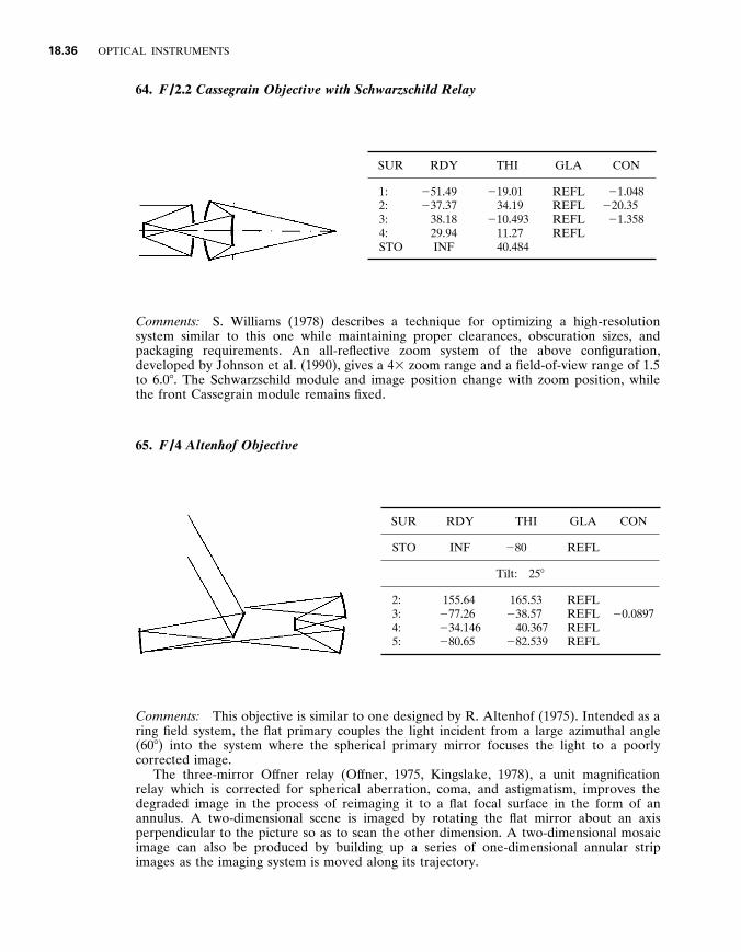
64 . F / 2 .2 Cassegrain Objecti y e with Schwarzschild Relay
SUR RDY THI GLA CON
1 : 2 : 3 : 4 : STO
2 51 . 49 2 37 . 37
38 . 18 29 . 94 INF
2 19 . 01 34 . 19
2 10 . 493 11 . 27 40 . 484
REFL REFL REFL REFL
2 1 . 048 2 20 . 35 2 1 . 358
Comments : S . Williams (1978) describes a technique for optimizing a high-resolution system similar to this one while maintaining proper clearances , obscuration sizes , and packaging requirements . An all-reflective zoom system of the above configuration , developed by Johnson et al . (1990) , gives a 4 3 zoom range and a field-of-view range of 1 . 5 to 6 . 0 8 . The Schwarzschild module and image position change with zoom position , while the front Cassegrain module remains fixed .
65 . F / 4 Altenhof Objecti y e
SUR RDY THI GLA CON
STO INF 2 80 REFL
Tilt : 25 8
2 : 3 : 4 : 5 :
155 . 64 2 77 . 26 2 34 . 146 2 80 . 65
165 . 53 2 38 . 57
40 . 367 2 82 . 539
REFL REFL REFL REFL
2 0 . 0897
Comments : This objective is similar to one designed by R . Altenhof (1975) . Intended as a ring field system , the flat primary couples the light incident from a large azimuthal angle (60 8 ) into the system where the spherical primary mirror focuses the light to a poorly corrected image .
The three-mirror Of fner relay (Of fner , 1975 , Kingslake , 1978) , a unit magnification relay which is corrected for spherical aberration , coma , and astigmatism , improves the degraded image in the process of reimaging it to a flat focal surface in the form of an annulus . A two-dimensional scene is imaged by rotating the flat mirror about an axis perpendicular to the picture so as to scan the other dimension . A two-dimensional mosaic image can also be produced by building up a series of one-dimensional annular strip images as the imaging system is moved along its trajectory .

REFLECTIVE AND CATADIOPTRIC OBJECTIVES 18 .37
66 . F / 4 .5 Shafer Four - mirror , Unobscured Objecti y e
SUR RDY THI GLA
1 : 158 . 1 2 71 . 21 REFL
Tilt angle : 2 16 . 44 8
STO 186 . 8 74 . 25 REFL
Tilt angle : 2 20 . 88 8
3 : 337 . 4 2 111 . 4 REFL
Tilt angle : 2 24 . 82 8
4 : 239 . 1 121 . 4 REFL
Tilt angle : 2 34 . 76 8 Image tilt angle : 2 24 . 29 8
Comments : This is a tilted and decentered-component infrared imaging system by David Shafer . Mirror tilts provide an unobscured path and help correct the aberrations . Thickness is measured along the deviated ray paths . With the reflection angle known , element decenter may be easily determined .
67 . F / 4 .5 Shafer Fi y e - mirror , Unobscured Objecti y e
SUR RDY THI GLA
1 : 2 239 . 5 2 160 . 2 REFL
Tilt angle : 6 . 4 8
2 : 2 228 . 9 48 . 69 REFL
Tilt angle : 2 9 . 2 8
3 : 2 75 . 94 2 37 . 24 REFL
Tilt angle : 2 19 . 01 8
STO 2 39 . 81 39 . 24 REFL
Tilt angle : 2 28 . 82 8
5 : 2 78 . 72 2 74 . 5 REFL
Tilt angle : 2 40 . 55 8 Image tilt angle : 2 11 . 28 8
Comments : Another all-spherical , tilted , and decentered-component infrared imager by
18 .38 OPTICAL INSTRUMENTS
D . Shafer is presented here . The entrance pupil is accessible and there is an intermediate image . A number of variations on this arrangement are described by Shafer (1978b) .
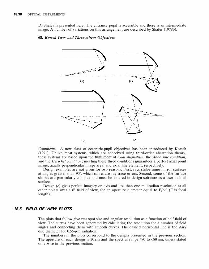
68 . Korsch Two - and Three - mirror Objecti y es
Comments : A new class of eccentric-pupil objectives has been introduced by Korsch (1991) . Unlike most systems , which are conceived using third-order aberration theory , these systems are based upon the fulfillment of axial stigmatism , the Abbe ́ sine condition , and the Herschel condition ; meeting these three conditions guarantees a perfect axial point image , axially perpendicular image area , and axial line element , respectively .
Design examples are not given for two reasons . First , rays strike some mirror surfaces at angles greater than 90 8 , which can cause ray-trace errors . Second , some of the surface shapes are particularly complex and must be entered in design software as a user-defined surface .
Design ( c ) gives perfect imagery on-axis and less than one milliradian resolution at all other points over a 6 8 field of view , for an aperture diameter equal to F / 6 . 0 (F is focal length) .
1 8 . 5 FIELD - OF - VIEW PLOTS
The plots that follow give rms spot size and angular resolution as a function of half-field of view . The curves have been generated by calculating the resolution for a number of field angles and connecting them with smooth curves . The dashed horizontal line is the Airy disc diameter for 0 . 55- m m radiation .
The numbers in the plots correspond to the designs presented in the previous section . The aperture of each design is 20 cm and the spectral range 480 to 680 nm , unless stated otherwise in the previous section .

REFLECTIVE AND CATADIOPTRIC OBJECTIVES 18 .39
FIGURE 7 Field-of-view plots : F / 1 . 25 on a flat image .
It should be kept in mind that these are representative designs : they have usually been optimized for a specific purpose ; they are meant to be a starting place for the design of a new system that may have entirely dif ferent requirements .
Flat-field designs show consistent performance out to the field angle for which the objective is optimized . Beyond this point , the graph leaps upward . Reoptimization is needed if the field of view is to be extended further ; a considerable increase in the average rms spot size may occur if this is attempted . The curved-image designs show a quadratic dependence with field angle .
Of f-axis and eccentric-pupil designs have rectangular fields with most of the field of view in one dimension only . Data plotted for these designs are representative of the larger field .
In Figs . 8 and 10 plots for the curved image designs are provided . The curvature of the image is adjusted to give optimum performance . Figures 7 and 9 are for the flat image designs .
FIGURE 8 Field-of-view plots : F / 1 . 25 on a curved image .

18 .40 OPTICAL INSTRUMENTS
FIGURE 9 Field-of-view plots : F / 4 on a flat image .
FIGURE 10 Field-of-view plots : F / 4 on a curved image .
1 8 . 6 DEFINITIONS
Abbe ́ number : A number that indicates the dispersion of a glass . Low dispersion glasses have a high Abbe number . Abbe ́ sine condition : A condition for zero coma , based on the requirement of equal marginal and paraxial magnifications . See Welford (1986) , Kingslake (1978) , or Korsch (1991) . anastigmatic : A surface or system free of astigmatism . Also stigmatic . aperture stop : The aperture that limits the size of the axial beam passing through the system ; the chief ray always passes through its center . aplanatic : A surface or system that is corrected for spherical aberration and coma . a s t i g m a t i s m : An aberration that generates two dif ferent focal positions for rays in two

REFLECTIVE AND CATADIOPTRIC OBJECTIVES 18 .41
perpendicular planes centered on the optical axis . These are called the sagittal and tangential planes . axial color : The variation in focal position with wavelength . axial stigmatism : A characteristic of a surface which is able to produce a perfect image of a single point object on-axis . catadioptric : An optical system composed of refractive and reflective elements : catoptric , reflective and dioptric , refractive . chief ray : A ray that passes through the center of the aperture stop and the edge of the image or object . coma : An aberration resulting from the change in magnification with ray height at the aperture , so that rays near the edge of the aperture are focused further from rays near the axis , for the same field point . conic constant : A constant defined by
k 5 2 e 2
where e is the eccentricity of the conic . distortion : The variation in magnification with field angle . entrance pupil : The image of the aperture stop in object space . The chief ray passes or appears to pass through the center of the entrance pupil . exit pupil : The image of the aperture stop in image space . The chief ray passes or appears to pass through the center of the exit pupil . focal ratio : The ef fective focal length of an objective divided by its entrance-pupil diameter . Focal ratio is also referred to as the FN , F-number , and speed . field cur y ature : Image curvature produced by the combined ef fects of astigmatism and Petzval curvature . When astigmatism is absent , the image surface coincides with the Petzval surface . field stop : An aperture that limits the size of an intermediate or final image . Herschel condition : A condition for invariance of aberrations with change in axial conjugates . See Welford (1986) and Korsch (1991) . higher - order aberrations : Aberrations defined by the higher-order terms in the aberration power series expansion . See Welford (1986) and Schulz (1988) . lateral color : An aberration that produces a dependence of image size on wavelength ; also called chromatic dif ference of magnification . Lyot stop : A real and accessible image of the aperture stop ; used to block stray light . marginal ray : A ray that passes through the center of the object or image and past the edge of the aperture stop . medial image : The image halfway between the sagittal and tangential images . See Welford (1986) . monocentric system : An optical system in which all surfaces are concentric about the chief ray . oblique spherical aberration : A higher - order aberration that is the variation of spherical aberration with field angle .
optical axis : The axis about which all optical elements are symmetric . In tilted and decentered systems , each element has a unique optical axis .

18 .42 OPTICAL INSTRUMENTS
Petz y al sum : The sum defined by
P 5 O f
n
where f is element power and n is the index of refraction . The reciprocal of the Petzval sum is the image radius of curvature . secondary magnification : System focal length divided by primary-mirror focal length . secondary spectrum : The dif ference in focal position between two wavelengths corrected for axial color and one other wavelength which is not . For example , the blue and red focus coincide and the yellow focus is axially displaced . spherical aberration : The only on-axis monochromatic aberration , spherical aberration results from rays at dif ferent heights coming to focus at dif ferent points along the optical axis . Smith (1990) , Rutten (1988) , Kingslake (1978) , Mackintosh (1986) , and Welford (1986) discuss aberrations . Welford specifically addresses aberrations . third - order aberrations : Any of the Seidel aberrations : spherical aberration , coma , astigmatism , Petzval curvature , and distortion . See Welford (1986) . y ignetting : The of f-axis clipping of light by apertures in an optical system . y irtual image : A real image is visible when a screen is placed at its location . The image is visible because rays from the object converge at the image . A virtual image is not visible when a screen is placed at its location since real rays do not converge . zonal spherical aberration : The incomplete correction of spherical aberration at radial zones in the aperture . For example , spherical aberration could be corrected for rays close to the center and edge of the aperture , but not corrected at other ray heights in the aperture .
1 8 . 7 REFERENCES
Abel , I . and M . Hatch , ‘‘The Pursuit of Symmetry in Wide-Angle Reflective Optical Designs , ’’ SPIE 237 : 271 (1980) .
Abel , I ., ‘‘Mirror Systems : Engineering Features , Benefits , Limitations and Applications , ’’ SPIE 531 : 121 (1985) .
Altenhof , R ., ‘‘The Design of a Large Aperture Infrared Optical System , ’’ SPIE 62 : 129 (1975) . Amon , M ., ‘‘Large Catadioptric Objective , ’’ U . S . Patent 3 , 711 , 184 , 1973 . Baker , J ., ‘‘The Solid Glass Schmidt Camera and a New Type of Nebular Spectrograph , ’’ Proc . Am . Phil . Soc . 82 : 323 (1940a) .
Baker , J ., ‘‘A Family of Flat-Field Cameras , Equivalent in Performance to the Schmidt Camera , ’’ Proc . Amer . Phil . Soc . 82 (3) : 339 (1940b) .
Baker , J ., ‘‘Schmidt Image Former with Spherical Abberation Corrector , ’’ U . S . Patent 2 , 458 , 132 , 1945 .
Baker , J ., Amateur Telescope Making , Book Three , Scientific American , Inc ., 1953 , p . 1 . Baker , J ., ‘‘Correcting Optical System , ’’ U . S . Patent 3 , 022 , 708 , 1962 . Baker , J ., ‘‘On Improving the Ef fectiveness of Large Telescopes , ’’ IEEE Transact . AES - 5 , (2) : 261 (1969) .
Baker , J ., ‘‘Explorations in Design , ’’ SPIE 147 : 102 (1978) . Bouwers , A ., Achie y ements in Optics , Elsevier , Amsterdam , 1950 . Brueggeman , H . Conic Mirrors , Focal Press , 1968 . Brunn , M ., ‘‘Unobstructed All-reflecting Telescopes of the Schiefspiegler Type , ’’ U . S . Patent 5 , 142 , 417 , 1992 .
Buchroeder , R ., ‘‘Catadioptric Designs , ’’ OSC , University of Arizona , Technical Report 68 , May , 1971a .

REFLECTIVE AND CATADIOPTRIC OBJECTIVES 18 .43
Buchroeder , R ., ‘‘Fundamentals of the TST , ’’ OSC , University of Arizona , Technical Report 68 , May , 1971b .
Canzek , L ., ‘‘High Speed Catadioptric Objective Lens System , ’’ U . S . Patent 4 , 547 , 045 , 1985 . Chretien , M ., ‘‘Le Telescope de Newton et le Telescope Aplanatique , ’’ Re y . d ’ Optique (2) : 49 (1922) . Cook , L ., ‘‘Three-Mirror Anastigmat Used Of f-Axis in Aperture and Field , ’’ SPIE 183 : 207 (1979) . Cook , L ., ‘‘Three-Mirror Anastigmatic Optical Systems , ’’ U . S . Patent 4 , 265 , 510 , 1981 . Cook , L ., ‘‘The Last Three-Mirror Anastigmat (TMA)?’’ SPIE Proceedings vol . CR 41 : 310 (1992) . Couder , A ., Compt . Rend . Acad . Sci . Paris , 183 , II , 1276 , p . 45 (1926) . Courtes , G ., ‘‘Optical Systems for UV Space Researches , ’’ From New Techniques in Space
Astronomy , D . Reidel Publishing Company , Dordrecht , Holland , 1971 . Courtes , G ., P . Cruvellier , M . Detaille , and M . Saisse , Progress in Optics vol . XX , 1983 , p . 3 . Eisenburg , S . and E . Pearson , ‘‘Two-Mirror Three-Surface Telescope , ’’ SPIE 751 : 24 (1987) . Everhart , E . and J . Kantorski , ‘‘Dif fraction Patterns Produced by Obstructions in Reflective Telescopes of Modest Size , ’’ Astronomical Journal 64 (Dec . ) : 455 (1959) .
Figosky , J ., ‘‘Design and Tolerance Specification of a Wide-Field , Three-Mirror , Unobscured , High-Resolution Sensor , ’’ SPIE 1049 : 157 (1989) .
Fischer , R ., ‘‘What’s So Dif ferent About IR Lens Design?’’ SPIE Proceedings Vol . CR 41 : 117 (1992) . Fjeidsted , T ., ‘‘Selectable Field-of-View Infrared Lens , ’’ U . S . Patent 4 , 453 , 800 , 1984 . Gabor , D ., British Patent 544 , 694 , 1941 . Gascoigne , S ., ‘‘Recent Advances in Astronomical Optics , ’’ Applied Optics 12 : 1419 (1973) . Gelles , R ., ‘‘A New Family of Flat-Field Cameras , ’’ Applied Optics 2 (10) : 1081 (1963) . Gelles , R ., ‘‘Unobscured Aperture Stigmatic Telescopes , ’’ Optical Engineering 13 (6) : 534 (1974) . Gelles , R ., ‘‘Unobscured-Aperture Two-Mirror Systems , ’’ Journal of the Optical Society of America
65 (10) : 1141 (1975) . Hallam , K ., B . Howell , and M . Wilson , ‘‘Wide-Angle Flat Field Telescope , ’’ U . S . Patent 4 , 598 , 981 , 1986 .
Hawkins , D . and E . Linfoot , ‘‘An Improved Type of Schmidt Camera , ’’ Monthly Notices Royal Astronomical Soc . 105 : 334 (1945) .
Houghton , J ., ‘‘Lens System , ’’ U . S . Patent 2 , 350 , 112 (1944) . Johnson , R ., J . Hadaway , and T . Burleson , ‘‘All-Reflective Four-Element Zoom Telescope : Design and Analysis , ’’ SPIE 1354 : 669 (1990) .
King , W ., ‘‘Unobscured Laser-Beam-Expander Pointing System with Tilted Spherical Mirrors , ’’ Applied Optics 13 (1) : 21 (1974) .
Kingslake , R ., Lens Design Fundamentals , Academic Press , Inc ., New York , 1978 . Korsch , D ., ‘‘Two Well-Corrected Four-Mirror Telescopes , ’’ Applied Optics 13 (8) : 1767 (1974) . Korsch , D ., ‘‘Anastigmatic Three-Mirror Telescope , ’’ Applied Optics 16 (8) : 2074 (1977) . Korsch , D ., ‘‘Anastigmatic Three-Mirror Telescope , ’’ U . S . Patent 4 , 101 , 195 (1978) . Korsch , D ., ‘‘Wide-Field Three-Mirror Collimator , ’’ U . S . Patent 4 , 737 , 021 , 1988 . Korsch , D ., Reflecti y e Optics , Academic Press , San Diego , Calif . 1991 . Kutter , A ., ‘‘A New Three-mirror Unobstructed Reflector , ’’ Sky and Telescope , Jan . 1975 , p . 46 ; Feb . 1975 , p . 115 .
Laiken , M ., Lens Design , Marcel Dekker , Inc ., New York , 1991 . Leonard , A ., ‘‘New Horizons for Tilted-Component Telescopes , ’’ in Ad y anced Telescope Making
Techniques , Willmann-Bell Inc ., Richmond , Va ., 1986a , p . 110 . Leonard , A ., ‘‘T . C . T . ’s (Tilted Component Telescopes) , ’’ in Ad y anced Telescope Making Techniques , Willmann-Bell Inc ., Richmond , Va ., 1986b , p . 131 .
Linfoot , E ., Recent Ad y ances in Optics , Oxford Univ . Press , London , 1955 . Mackintosh , A ., Ad y anced Telescope Making Techniques , Willmann-Bell Inc ., Richmond , Va ., 1986 . Maksutov , D ., J . Opt . Soc . Am . , 34 : 270 (1944) . McCarthy , E ., ‘‘Anastigmatic Catoptric Systems , ’’ U . S . Patent 3 , 062 , 101 , 1959 . Mandler , W ., ‘‘Reflecting Mirror and Lens System of the Cassegrain Type , ’’ U . S . Patent 2 , 726 , 574 , 1951 .
Mangin , A ., ‘‘Memorial de L’of ficier du Genie (Paris) , ’’ 25 (2) : 10 , 211 (1876) .

18 .44 OPTICAL INSTRUMENTS
Manly , P ., Unusual Telescopes , Cambridge Univ . Press , Cambridge , England , 1991 . Maxwell , J ., Catadioptric Imaging Systems , Elsevier , New York , 1972 . Meinel , A ., ‘‘Aspheric Field Correctors for Large Telescopes , ’’ Astrophysical Journal 118 : 335 (1953) . Meinel , A . and R . Shack , ‘‘A Wide-Angle All- Mirror UV Camera , ’’ Optical Sciences Center Tech . Rep . No . 6 , 1966 .
Meinel , A . and M . Meinel , SPIE 332 : 178 (1982) . Meinel , A ., M . Meinel , D . Su , and Ya-Nan Wang , ‘‘Four-Mirror Spherical Primary Submillimeter
Telescope Design , ’’ Applied Optics 23 (17) : 3020 (1984) . Of fner , A ., ‘‘New Concepts in Projection Mask Aligners , ’’ Optical Engineering 14 (2) : 130 (1975) . Olsen , E ., ‘‘A Schupmann for Amateurs , ’’ in Ad y anced Telescope Making Techniques , Willmann-Bell Inc ., Richmond , Va ., 1986 , p . 223 .
Owen , R ., ‘‘Easily Fabricated Wide-Angle Telescope , ’’ SPIE 1354 : 430 (1990) . Paul , M ., Re y . Opt . 14 : 169 (1935) . Pollock , D ., ‘‘An All-Reflective , Wide Field of View Collimator , ’’ SPIE 751 : 135 (1987) . Rao , D ., ‘‘Design of a Near Dif fraction-Limited Catadioptric Lens , ’’ SPIE 766 : 220 (1987) . Richardson , E . and C . Morbey , ‘‘Optical Design of an Astrometric Space Telescope , ’’ SPIE 628 : 197
(1986) . Robb , P ., ‘‘Three-mirror Telescopes : Design and Optimization , ’’ Applied Optics 17 (17) : 2677 (1978) . Roesch , M ., Tr . Int . Astr . Union . , Vol . VII : 103 (1950) . Rosin , S ., ‘‘Corrected Cassegrain System , ’’ Applied Optics 3 (1) : 151 (1964) . Rosin , S ., ‘‘Ritchey-Chretien Corrector System , ’’ Applied Optics 5 (4) : 675 (1966) . Ross , F ., ‘‘Lens Systems for Correcting Coma or Mirrors , ’’ Astrophysics Journal , 81 : 156 (1935) . Rumsey , N ., ‘‘Telescopic System Utilizing Three Axially Aligned Substantially Hyperbolic Mirrors , ’’ U . S . Patent 3 , 460 , 886 , 1969 .
Rutten , H . and M . Venrooij , Telescope Optics , Willmann-Bell , Inc ., Richmond , Va ., 1988 . Sasian , J ., ‘‘Review of Methods for the Design of Unsymmetrical Optical Systems , ’’ SPIE 1396 : 453 (1990a) .
Sasian , J ., ‘‘Design of a Schwarzschild Flat-Field , Anastigmatic , Unobstructed , Wide-Field Tele- scope , ’’ Optical Engineering 29 (1) January , p . 1 (1990b) .
Schmidt , B ., Mitt . Hamburg . Sternwart 7 (36) (1932) . Schroeder , D ., ‘‘All-Reflecting Baker-Schmidt Flat-Field Telescopes , ’’ Applied Optics 17 (1) : 141 (1978) .
Schroeder , D ., Astronomical Optics , Academic Press , Inc ., San Diego , Calif ., 1987 . Schulte , D ., ‘‘Auxiliary Optical Systems for the Kitt Peak Telescopes , ’’ Applied Optics 2 (2) : 141 (1963) .
Schulte , D ., ‘‘Anastigmatic Cassegrain Type Telescope , ’’ Applied Optics 5 (2) : 309 (1966a) . Schulte , D ., ‘‘Prime Focus Correctors Involving Aspherics , ’’ Applied Optics 5 (2) : 313 (1966b) . Schulz , G ., ‘‘Aspheric Surfaces , ’’ Progress in Optics XXV : 351 (1988) . Schupmann , L ., ‘‘Die Medial-Fernrehre , ’’ Leipzig (1899) . Schwarzschild , K ., ‘‘Untersuchungen zur Geometrischen Optik , II ; Theorie der Spiegelteleskope , ’’ Abh . der Konigl . Ges . der Wiss . zu Gottingen , Math . - phys . Klasse , 9 , Folge , Bd . IV , No . 2 (1905) .
Shafer , D ., ‘‘Well Baf fled Two-Mirror Corrector for a Parabola , ’’ Applied Optics 16 (5) : 1175 (1977) . Shafer , D ., ‘‘Design With Two-Axis Aspheric Surfaces , ’’ SPIE 147 : 171 (1978a) . Shafer , D ., ‘‘Four-Mirror Unobscured Anastigmatic Telescopes with All-Spherical Surfaces , ’’ Applied Optics 17 (7) : 1072 (1978b) .
Shafer , D ., ‘‘20 Degree Field-of-View Strip Field Unobscured Telescope with Stray Light Rejection , ’’ presented Oct . 31 in San Francisco at Optical Society of America Annual Meeting , 1978c .
Shafer , D ., ‘‘30 Degree F / 1 . 0 Flat Field Three Mirror Telescope , ’’ presented Oct . 31 in San Francisco at Optical Society of America Annual Meeting , 1978d .
Shafer , D ., ‘‘Simple Method for Designing Lenses , ’’ SPIE 237 : 234 (1980a) .

REFLECTIVE AND CATADIOPTRIC OBJECTIVES 18 .45
Shafer , D ., ‘‘A Simple Unobstructed Telescope with High Performance , ’’ Telescope Making 41 : 4 (TM 41) .
Shafer , D ., ‘‘Optical Design with Only Two Surfaces , ’’ SPIE 237 : 256 (1980b) . Shafer , D ., ‘‘Well-Corrected Two-Element Telescope with a Flat Image , ’’ Optica Acta 28 (11) : 1477
(1981) . Shafer , D ., ‘‘An All-Reflective Infrared Target Simulator Design , ’’ October OSA Workshop on Optical Fabrication and Testing , 1988 .
Shenker , M ., ‘‘High Speed Catadioptric Objective in Which Three Corrector Elements Define Two Power Balanced Air Lenses , ’’ U . S . Patent 3 , 252 , 373 , 1966 .
Sigler , R ., ‘‘Compound Catadioptric Telescopes with All-Spherical Surfaces , ’’ Applied Optics 17 (10) : 1519 (1978) .
Smith , W ., Modern Optical Engineering , McGraw-Hill , Inc ., New York , 1990 . Smith , W ., Modern Lens Design , McGraw-Hill , Inc ., New York , 1992 . Sonnefeld , A ., ‘‘Photographic Objective , ’’ U . S . Patent 2 , 141 , 884 , 1938 . Thompson , K ., ‘‘Aberration Fields in Tilted and Decentered Optical Systems , ’’ Ph . D . dissertation , Optical Sciences Center , University of Arizona , 1980 .
Wang , D ., L . Gardner , W . Wong , and P . Hadfield , ‘‘Space Based Visible All-Reflective Stray Light Telescope , ’’ SPIE 1479 : 57 (1991) .
Warmisham , A ., British Patent 551 , 112 , 1941 . Wayman , R ., ‘‘The Monocentric Schmidt-Cassegrain Cameras , ’’ Proc . Phys . Soc . (London) , 63 : 553 (1944) .
Welford , W ., Aberrations of Optical Systems , Adam Hilger Ltd ., Bristol , England , 1986 . Wetherell , W . and P . Rimmer , ‘‘General Analysis of Aplanatic Cassegrain , Gregorian and Schwarzschild Telescopes , ’’ Applied Optics 11 : no . 12 , 2817 (1972) .
Wetherell , W . and D . Womble , ‘‘All-Reflective Three Element Objective , ’’ U . S . Patent 4 , 240 , 707 , 1980 .
Williams , S ., ‘‘Design Techniques for WFOV High-Resolution Reflecting Optics , ’’ SPIE 147 : 94 (1978) .
Williams , S ., ‘‘On-Axis Three-Mirror Anastigmat with an Of fset Field of View , ’’ SPIE 183 : 212 (1979) . Wilson , R ., ‘‘Corrector Systems for Cassegrain Telescopes , ’’ Applied Optics 7 (2) : 253 (1968) . Wright , F ., ‘‘An Aplanatic Reflector With a Flat-Field Related to the Schmidt Telescope , ’’
Astronomical Society of the Pacific 47 : 300 (1935) . Wynne , C ., ‘‘Field Correctors for Large Telescopes , ’’ Applied Optics 4 (9) : 1185 (1965) . Wynne , C ., ‘‘Maksutov Spectrograph Cameras , ’’ Monthly Notices Royal Astronomical Society 153 : 261 (1971) .
Wynne , C ., ‘‘Field Correctors for Astronomical Telescopes , ’’ Progress in Optics , X : 139 (1972a) . Wynne , C ., ‘‘Five Spectrograph Camera Designs , ’’ Monthly Notices Royal Astronomical Society 157 : 403 (1972b) .
Wynne , C ., ‘‘A New Wide-Field Triple Lens Paraboloid Field Corrector , ’’ Monthly Notices Royal Astronomical Society 167 : 189 (1974) .
Wynne , C ., ‘‘Shorter than a Schmidt , ’’ Monthly Notices Royal Astronomical Society 180 : 485 (1977) .