Embed Size (px)
Citation preview

January 2016 16-1 Design Criteria Ch. 16
CHAPTER 16
Design Guidelines for Wastewater Treatment Systems
Using Spray Irrigation
16.1 General
16.1.1 General
16.1.2 Applicability
16.1.3 Location
16.1.4 Topography
16.1.5 Soils
16.2 Soil Investigations
16.2.1 General
16.2.2 Soil Soil Mapping
16.2.3 Soil Definitions
16.3 Preapplication Treatment Requirements
16.3.1 General
16.3.2 BOD and TSS Reduction, and Disinfection
16.3.3 Treatment and Storage Ponds
16.4 Inorganic Constituents of Treated Wastewater
16.5 Protection of Irrigation Equipment
16.6 Determination of Design Application Rates
16.6.1 General
16.6.2 Design Values
16.7 Determination of Design Wastewater Loading
16.7.1 General
16.8 Nitrogen Loading and Crop Selection and Management
16.8.1 General
16.8.2 Nitrogen Loading
16.8.3 Organic/BOD Loading
16.8.4 Cover Crop Selection and Management
January 2016 16-2 Design Criteria Ch. 16
16.9 Land Area Requirements
16.9.1 General
16.9.2 Field Area Requirements
16.9.3 Buffer Zone Requirements
16.10 Storage Requirements
16.10.1 General
16.10.2 Estimation of Storage Requirements Using Water Balance Calculations
16.11 Distribution System
16.11.1 General
16.11.2 Surface Spreading
16.11.3 Sprinkler Spreading
16.12 Spray Irrigation of Wastewater from Gray Water Facilities
16.12.1 General
16.12.2 Site Location
16.12.3 Design Flow
16.12.4 Pretreatment
16.12.5 Field Requirements
16.12.6 Application Equipment
16.12.7 Operation of System
16.13 Plan of Operation and Management
16.13.1 Introduction
16.13.2 Management and Staffing
16.13.3 Facility Operation and Management
16.13.4 Monitoring Program
16.13.5 Records and Reports
January 2016 16-3 Design Criteria Ch. 16
SPRAY IRRIGATION
LAND TREATMENT SYSTEMS
16.1 General
16.1.1 General
This chapter provides guidelines and criteria for the design of surface spray irrigation
land treatment systems.
The wastewater loading rate is limited by the maximum amount of a particular
wastewater constituent that can be applied to a specific site. For wastewater from
municipalities, the limiting design factor is usually either the hydraulic capacity of the
soil or the nitrogen content of the wastewater. For industrial wastewater, the limiting
design factor may be the hydraulic capacity of the soil, nitrogen or any other wastewater
constituent such as metals, organics, etc.
16.1.2 Applicability
Spray irrigation wastewater treatment systems must be designed and operated so that
there is no direct discharge to surface waters. Treatment consists of evaporation directly
to the atmosphere, by transpiration to the atmosphere via vegetation uptake and by
percolation to groundwater. A State of Tennessee Operation Permit (SOP) is required for
operation of spray irrigation land treatment systems.
16.1.3 Location
The spray irrigation treatment site should be relatively isolated, easily accessible and not
susceptible to flooding. The site can be developed on agricultural land and/or forests or
can include parks, golf courses, etc. Site location shall take into account dwellings,
roads, streams, etc. A site evaluation by the Division of Water Pollution will be required
before review of the Engineering Report and/or application for an SOP.
16.1.4 Topography
Maximum grades for wastewater spray fields should be limited to 8% for row crops, 15%
for forage crops and 30% for forests. The greater the slope the greater potential for
lateral subsurface drainage, ponding and extended saturation of the soil. Depressions,
sink holes, etc., are to be avoided.
16.1.5 Soils
The infiltrative capacity of soil is a critical factor to be considered when designing any
type of spray irrigation system. If the profile of a particular soil considered for spray
irrigation extended to a significant depth without a restrictive horizon (most limiting
layer), the ability to load that soil per unit area would be relatively high.

January 2016 16-4 Design Criteria Ch. 16
On the other extreme, if a soil being considered for spray irrigation has a shallow
restrictive horizon, the ability to load that soil would be lower relative to the deeper soil.
Depth to restrictive horizon, soil permeability and slope of the restrictive horizon are
factors that control the amount and rate at which ground water can exit an area. If the
amount of treated effluent applied to an area, in combination with rainfall over the area
and groundwater moving into the area, exceed the soil profile’s ability to transmit the
water away from the application area, surface runoff of wastewater effluent will likely
occur.
Evaluation of a soil area’s suitability for spray irrigation should take into consideration
limiting aspects of the soil profile. Sites with shallow restrictive horizons overlain by
low permeability soils represent one of the more limited scenarios for spray irrigation and
the application rate and/or application area should be suitably modified.
Also critical when designing systems in soils with shallow restrictive horizons are the
presence and location of hydrologic boundaries such as drainage ways and waterways.
These hydrologic boundaries provide an outlet for ground water discharge. Not only is it
critical to identify these features in consideration of appropriate setbacks/buffers, it is
also critical to factor in their role in the overall hydrologic cycle of the landscape.
Horizons along which lateral flow would be expected include, but are not necessarily
limited to: bedrock, fragipans, and zones with high clay percentage overlain by more
permeable soil.
Spray irrigation design submittals should take into consideration all factors influencing
the infiltrative capacity of the soil and the ability of the soil and site to transport ground
water away from the application area. Spray pattern designs must properly utilize the site
soil and topography. It should be noted that the use of historical information from
existing systems installed and operated in similar soils, with documented loading rates,
landscape positions and design conditions similar to the proposed system may be
applicable. Therefore, soils that have been highly compacted and/or disturbed, such as
old road beds, foundations, etc., must be excluded when evaluating suitable areas for
surface spray irrigation systems.
16.2 Soil Investigations
16.2.1 General
Preliminary soil investigations should be done to identify areas best suited for surface
spray irrigation. The proposed surface spray area must be mapped at sufficient accuracy
to identify each soils series (or lowest possible level of soil classification) present and the
boundary location between series. Once those areas are identified, the more detailed
procedures outlined below will be employed.
It is required that all soil investigations be performed by a soil scientist currently on the
Ground Water Protection list of approved soil scientists/soil consultants.
For spray irrigation wastewater treatment systems, moderately permeable and well-
drained soils are desirable. However, the use of any soil is acceptable if it meets the
following four (4) criteria:

January 2016 16-5 Design Criteria Ch. 16
1. The applied effluent loading rate does not exceed the applicable hydraulic loading
rate in Table 16-1. The applicable hydraulic loading rate is determined by a
detailed site evaluation in which the site is mapped utilizing soil borings and pits
to determine the physical properties of soil horizons and soil map units.
2. The applied effluent maximum loading rate does not exceed 10% of the minimum
NRCS saturated vertical hydraulic conductivity (KSAT) for the soil series or 0.25
GPD/SF whichever is least. Note: this may have to be lowered based upon the
results of the nutrient loading rate calculation per Equation 16-1.
3. The soil does not have a restrictive horizon within its top twenty (20) inches.
4. The soil is well drained, or capable of being drained.
It is desirable to have a minimum depth of twenty (20) inches of undisturbed soil
above a restrictive horizon (eg., rock, fragipan, high water table, etc.)

January 2016 16-6 Design Criteria Ch. 16
TABLE 16-1
Hydraulic Loading Rates (GPD/SF) – For Spray Irrigation Systems
(Reference: EPA/R-00/08, February 2002, “Onsite Wastewater Treatment Systems Manual”)
TEXTURE
STRUCTURE
HYDRAULIC
LOADING
RATE*
SHAPE GRADE
GPD / SF GPD / SF
BOD ≤ 150
mg/L BOD ≤ 30 mg/L
Coarse Sand, NA NA 0.80 NA
Loamy Coarse Sand
Sand NA NA NA
Loamy Sand,
Single Grain Structureless 0.40
1.00
Fine Sand,
Loamy Fine Sand,
Very Fine Sand,
Loamy Very Fine
Sand
Coarse Sandy Loam,
Sandy Loam
Massive Structureless 0.20 0.60
Platy Weak 0.20 0.50
Moderate, Strong
Blocky, Weak 0.20 0.70
Granular Moderate, Strong 0.40 1.00
Loam
Massive Structureless 0.20 0.50
Platy Weak, Moderate,
Strong
Angular, Blocky Weak 0.40 0.60
Granular,
Subangular Moderate, Strong
0.60 0.80
Silt Loam
Massive Structureless 0.20
Platy Weak, Moderate,
Strong
Angular, Blocky, Weak 0.40 0.60
Granular,
Subangular Moderate, Strong
0.60 0.80
Sandy Clay Loam, Massive Structureless

January 2016 16-7 Design Criteria Ch. 16
Clay Loam,
Silty Clay Loam Platy
Weak, Moderate,
Strong
Angular, Blocky Weak 0.30
Granular,
Subangular Moderate, Strong
0.60
Sandy Clay
Clay,
Silty Clay
Massive Structureless
Platy Weak, Moderate,
Strong
Angular, Blocky Weak
Granular,
Subangular Moderate, Strong
0.20 0.30
* Maximum allowable is 0.25 GPD/SF; however all hydraulic
loading rates may be adjusted based upon special site specific
evaluations approved by TDEC.
These soils are considered unacceptable for spray irrigation.

January 2016 16-8 Design Criteria Ch. 16
16.2.2 Soil Mapping
The mapping procedure will usually begin with the property/land being generally
evaluated to delineate or separate areas with suitable characteristics. This procedure will
save time and money since some areas will be too shallow, too wet, too steep, etc.
Adequate ground control is mandatory for all sites. The ground control is necessary to
reproduce the map if needed. All located coordinates (soil map boundaries and pit
locations) must be shown on the final Water Pollution Control (WPC) Soil Map.
Soil data collection shall be based upon one, or combination of the following:
1. Grid staking at intervals sufficient to allow the soils scientist to attest to the
accuracy of the map for the intended purpose;
2. Mapping of pits and critical auger locations using dual frequency survey grade
Global Positioning System (GPS) units.
3. Other controls adequate to map the location of pits, physical features, and
separations.
4. Grid stakes and GPS data points must be locatable to within two (2) feet of
distance shown.
5. The ground control has to correlate to the exterior boundaries of the property so as
to show the location of the soils areas within the bounds of the project and must
be certified by a Registered Land Surveyor per TCA 62-18-102(3).
The soil scientists are responsible for conducting a sufficient number of borings that, in
their professional opinion, will allow them to certify the soils series (or lowest possible
level of soil classification) present, identify boundaries between series, and describe each
soil horizon as to color, depth to restrictive horizon, and depth to rock. Any
redoximorphic features observed are to be described. This delineation should be based
upon the texture and structure of the soils to a depth of forty-eight (48) inches or
restrictive horizon whichever is shallower.
After the mapped soils area is established and marked, soil borings to a minimum depth
of forty-eight (48) inches or restrictive horizon, whichever is shallowest, shall be taken at
sufficient intervals to identify and map the boundaries of the soils series (or lowest
possible level of soil classification) present on the site. The exact number and location of
borings will be determined by the soils scientist in consultation with the design engineer.
Sufficient borings should be made to identify any dissimilar soils accounting for more
than 10 percent of the total proposed surface spray irrigation area.
The soil scientist shall excavate an adequate number of pits to determine the typical
profiles and soils characteristics that are expected for all soils mapped. It is
recommended that a minimum of two (2) pits per acre in polygons of qualifying soils be
excavated; however, the actual number and location of pits will be left to the best
professional judgment of the soil scientist. If less than two (2) pits per acre are utilized,
the soil scientist must include the rationale in notes on the WPC Soil Map.

January 2016 16-9 Design Criteria Ch. 16
The pit description must be entered onto a pedon sheet and submitted with the soils map
and engineering report. The “Soil Description” should include all of the information
contained on form NRCS-Soils-232G (5-86), U.S. Department of Agriculture, Natural
Resources Conservation Service (as shown in Chapter 17, Appendix D).
In their description of the pit profiles, the soil scientists must describe the soil’s structure,
texture, color, and any redoximorphic features present. They should also describe root
depth and presence of macropores, etc. The series name or lowest possible level of soil
classification will be recorded. The depth to hard rock using an auger or a tile probe must
be specified if the depth is less than forty-eight (48) inches and estimated if greater than
forty-eight (48) inches. The auger borings and soil backhoe pits should be located,
numbered and shown on the WPC Soil Map. The soil scientist will be required to
prepare and sign a detailed certification statement for each site evaluated as follows:
Water Pollution Control Soil Map Completed by:
Signature Date
John/Jane Doe, Soils Consultant
The following statement should appear on the map:
“I, (Soils Consultant’s Name) affirm that this Water Pollution Control Soil Map has
been prepared in accordance with accepted standards of soil science practice and the
standards and methodologies established in the NRCS Soil Survey Manual and USDA
Soil Taxonomy. No other warranties are made or implied.”
Soil profile information and pit excavation, as described in these design criteria, are
additional requirements deemed necessary to properly assess an area’s suitability for
surface spray irrigation.

January 2016 16-10 Design Criteria Ch. 16
16.2.3 Soil Definitions
Soil Horizons (layers): Soil is made up of distinct horizontal layers; these layers are
called horizons and display vertical zones. They range from rich, organic upper layers
(humus and topsoil) to underlying rocky layers (subsoil, regolith and bedrock).
Soil horizons develop due to the nature of soil formation. Soil is the product of the
weathering of parent material (i.e. bedrock), accompanied by the addition of organic
matter. The method for naming the soil horizons is quite simple as the Figure 16.1
shows. In the simplest naming system, soils horizons are designated O (organic), A
(topsoil), B (mineral soil), C (weathered parent material), and R is the unweathered rock
(bedrock) layer that is beneath all the other layers. The horizons of most importance to
plant growth and forest health are the O and A horizons. The litter layer found covering
the soil is also of interest because it provides most of the organic matter found in the O
and A horizons.

January 2016 16-11 Design Criteria Ch. 16
FIGURE 16.1
The Litter Layer is the topmost layer on the forest floor. It consists of leaves,
needles and other non-decomposed material on the forest floor. While this is not
considered part of the soil, it is interesting to measure the depth of the litter layer
when sampling the soil. The depth of the litter layer can vary greatly even within
a particular site. Because of this, several measurements are required to attempt to
characterize litter layer depth. The litter layer can be considered part of the
overall soils depth.
The O-Horizon primarily consists of decomposed organic matter and has a dark
rich color, increased porosity, and increased aggregate structure (larger soil
“clumps”). The depth of the O horizon is measured from the surface of the soil
(after the litter layer has been cleared away) to the point where the darker organic
color changes to a slightly lighter colored soil that contains increased mineral
particles in addition to organic matter.

January 2016 16-12 Design Criteria Ch. 16
The transition from the O to the A horizon can also be recognized by a significant
increase in the mineral soil particles. In many urban soils, the O horizon may
very thin if it exists at all. The O horizon can also be considered part of the
overall soils depth.
The A-Horizon is the mineral “topsoil” and consists of highly weathered parent
material (rocks), which is somewhat lighter in color than the O horizon due to a
decrease in organic matter. The particles in the A horizon are more granular and
“crumb-like”. Seeds germinate and plant roots grow in this layer. It is made up
of humus (decomposed organic matter) mixed with mineral particles. The depth
of the A horizon is measured from the region of color changes from the dark O
horizon to the transition to the B horizon. The transition to the B horizon can be
identified by increased clay content (see below) and the absence of organic
material: no root hairs, small pieces of needle, etc.
The most thorough soil study involves analysis on separate O and A horizon
samples. This requires separating and storing O and A horizon samples. It also
involves completing the entire soil analysis on both the O and A samples. If this
is not possible, the O and A samples can be combined (or composited) and the
analysis can be completed on the O and A sample together.
The B-Horizon is also called the subsoil - this layer is beneath the A horizon and
above the C horizon. It contains clay and mineral deposits (like iron, aluminum
oxides, and calcium carbonate) that it receives when soil solution containing
dissolved minerals drips from the soil above.
The B horizon is identified by increased clay content which makes the soil hold
together when moist. A simple test for clay content is to moisten a small handful
of soil and attempt to smear a small portion up the forefinger. Soils high in clay
will hold together and form a “ribbon”, soils with more sand and silt will be
granular and fall apart. It is lighter in color and often may be reddish due to the
iron content.
The C Horizon (layer beneath the B Horizon) consists of porous rock (broken-up
bedrock, bedrock with holes). It is also called regolith or saprolyte which means
"rotten rock." Plant roots do not penetrate into this layer; very little organic
material is found in this layer.
The R-Horizon is the unweathered rock (bedrock) layer that is beneath all the
other layers. For the purposes of drip dispersal designs, the R horizon is
considered an impermeable layer.
Water Pollution Control (WPC) Soils Map. A first order survey as defined in
the Soil Survey Manual, United States Department of Agriculture, October 1993.
These surveys are made for various land use that requires detailed soils
information.

January 2016 16-13 Design Criteria Ch. 16
Map scale should be one (1) inch equals one hundred (100) feet or a scale that
will allow the map to fill a 24” x 36” plan sheet. These maps should have
adequate cartographic detail to satisfy the requirements of project. The WPC
Soils Map is essentially a special map that shows a very high degree of soil and
landscape detail. Baseline mapping standards for these WPC Soil Maps prepared
in support of surface spray irrigation should be a first order survey in accordance
with the current edition of the Soil Survey Manual, United States Department of
Agricultural, October 1993. Soil profile information and pit excavation, as
described in these design criteria are additional requirements deemed necessary to
properly assess an area’s suitability for surface spray irrigation. These maps
should be clearly marked or labeled as “Water Pollution Control Soil Map”.
Soil map unit. A unique collection of areas that have common soil
characteristics and/or miscellaneous physical and chemical features.
Soil scientist. A person having the experience and education necessary to
measure soil properties and classify soils per Soil Taxonomy, synonymous with
the term “soil consultant”.
Soil series. A group of soils having similar properties; the lowest level of soil
classification.
Most limiting horizon. A horizon in the soil (bedrock or fragipan) that either
provides the greatest impediment to or completely stops, the downward
movement of liquids through the soil.
16.3 Preapplication Treatment Requirements
16.3.1 General
Wastewater spray irrigation systems have a demonstrated ability to treat high strength
organic wastes to low levels. However, such systems require a high degree of
management with particular attention paid to organic loading rates and aeration of the
soil profile between wastewater applications.
The Division of Water Pollution requires that all domestic and municipal wastewaters
receive biological treatment prior to irrigation.
This is necessary to:
a. Protect the health of persons contacting the irrigated wastewater.
b. Reduce the potential for odors in storage and irrigation.
Some industrial wastewaters may be suitable for direct land treatment by irrigation under
intensive management schemes. The Division of Water Pollution Control will evaluate
such systems on a case-by-case basis.

January 2016 16-14 Design Criteria Ch. 16
16.3.2 BOD and TSS Reduction, and Disinfection
Preapplication treatment standards for domestic and municipal wastewaters prior to
storage and/or irrigation are as follows:
a. Sites Closed to Public Access
All wastewater must be treated to a level afforded by lagoons which are designed in
accordance with Chapter 9.
Disinfection is generally not required for restricted and fenced access land treatment
sites. The Division of Water Pollution Control may, however, require disinfection
when deemed necessary.
b. Sites Open to Public Access
Sites open to public access include golf courses, cemeteries, green areas, parks, and
other public or private land where public use occurs or is expected to occur.
Wastewater that is spray irrigated on public access sites must not exceed a 5-day
Biochemical Oxygen Demand and Total Suspended Solids of 30 mg/L, as a monthly
average. Disinfection to reduce E. coli bacteria to 23 colonies/100 mL is required.
The preapplication treatment standards for wastewater that is to be applied to public
access areas will be reviewed by the Division of Water Pollution Control on a
case-by-case basis. More stringent preapplication treatment standards may be
required as the Division of Water Pollution Control deems necessary. The Division
of Water Pollution Control recommends that the engineer give preference to
pretreatment systems that will provide the greatest degree of reliability.

January 2016 16-15 Design Criteria Ch. 16
16.3.3 Treatment and Storage Ponds
The storage pond and irrigation pump station must be hydraulically separate from the
treatment cells (i.e., pumping must not affect hydraulic detention time in these cells).
The Division of Water Pollution Control recommends the use of Chapter 9 of the Design
Criteria for Sewage Works, as well as the United States Environmental Protection
Agency's October 1983 Design Manual: Municipal Wastewater Stabilization Ponds as a
reference for design of preapplication treatment ponds.
16.4 Inorganic Constituents of Treated Wastewater
Inorganic constituents of effluent from preapplication treatment should be compared with
Table 16-2 to insure compatibility with land treatment site soils and cover crops.

January 2016 16-16 Design Criteria Ch. 16
Table 16-2
Recommended Values for Inorganic Constituents in Wastewater Surfaced Applied to Land
Potential Problem
and Constituent No Problem
Increasing
Problem
Severe
Problem
pH (Standard Units) 6.5 – 8.4 <5.0 or >9.0
Permeability
Electrical Conductivity (mho/cm) >0.50 <0.50 <2.0
Sodium Adsorption Ratio (a) <5.0 5.0 – 9.0 >9.0
Salinity
Electrical Conductivity (mho/cm) <0.75 0.75 – 3.0 >3.0
Anions:
Bicarbonate (meq/L) <1.5 1.5 – 8.5 >8.5
(mg/L as CaCO3) <150 150 – 850 >850
Chloride (meq/L) <3.0 3.0 – 10 >10
(mg/L) <100 100 – 300 >300
Fluoride (mg/L) <1.8
Cations:
Ammonia (mg/L as N) <5.0 5.0 – 30 >30
Sodium (meq/L) <3.0 3.0 – 9.0 >9.0
(mg/L) <70 70 or greater
Trace Metals (mg/L)
Aluminum <10
Arsenic <0.2
Beryllium <0.2
Boron <0.5 0.5 – 2.0 >2.0
Cadmium <0.02
Chromium <0.2
Cobalt <0.1
Copper <0.4
Iron <10
Lead <10
Lithium <2.5
Manganese <0.4
Molybdenum <0.02
Nickel <0.4
Selenium <0.04
Zinc <4.0
(a) Sodium Adsorption Ratio (SAR) = Na+1
SQR ( Ca+2
+ Mg+2
) / 2
Where, Na+1, Ca+2, and Mg+2 in wastewater are expressed in milliequivalents per liter(meq/L).
SQR represents “Square Root of”

January 2016 16-17 Design Criteria Ch. 16
16.5 Protection of Irrigation Equipment
Prior to pumping to the spray field distribution system, the wastewater must be screened
to remove fibers, coarse solids, oil and grease which might clog distribution pipes or
spray nozzles. As a minimum, screens with a nominal diameter smaller than the smallest
flow opening in the distribution system should be provided. Screening to remove solids
greater than one-half (½) the diameter of the smallest sprinkler nozzle is recommended
by some sprinkler manufacturers. The planned method for disposal of the screenings
must be provided.
Pressurized, clean water for backwashing screens should be provided. This backwash
may be manual or automated. Backwashed screenings should be captured and removed
for disposal. These screenings should not be returned to the storage pond(s) or
preapplication treatment system.
16.6 Determination of Design Application Rates
16.6.1 General
One of the key steps in the design of a spray irrigation system is to develop a "design
application rate" in gallons per day per square foot (GPD/SF). This value is derived from
either the hydraulic (water) loading rate (Lwh) based upon the most restrictive of (1) the
NRCS hydraulic conductivity data and the texture and structure (per Table 16-1), or (2)
the nutrient (nitrogen) loading rate (Lwn) calculations to determine design wastewater
loading(s) and, thus, spray irrigation field area requirements.
16.6.2 Design Values
The most limiting horizon, of each soil series shall be identified. Any surface condition
which limits the vertical or lateral drainage of the soil profile shall also be identified.
Examples of such conditions are shallow bedrock, a high water table, aquitards, and
extremely anisotropic soil permeability. Design considerations relative to the soils per
Section 16.1.5 must be used.
Sites with seasonal high groundwater less than twenty-four (24) inches deep may require
drainage improvements before they can be utilized for spray irrigation land treatment.
The design hydraulic conductivity at such sites is a function of the design of the drainage
system.
January 2016 16-18 Design Criteria Ch. 16
16.7 Determination of Design Wastewater Loading
16.7.1 General
The design wastewater loading is a function of:
a. Precipitation.
b. Evapotranspiration.
c. Design hydraulic conductivity rate.
d. Nitrogen loading limitations.
e. Other constituent (i.e., organic/BOD) loading limitations.
f. Groundwater and drainage conditions.
g. Average and peak design wastewater flows.
h. Soil denitrification rates
i. Rate of nitrogen uptake in site vegetation
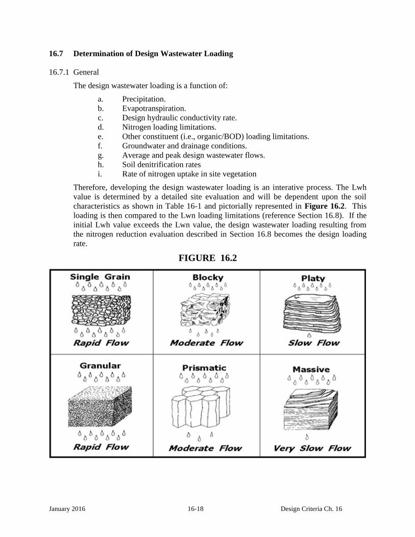
Therefore, developing the design wastewater loading is an interative process. The Lwh
value is determined by a detailed site evaluation and will be dependent upon the soil
characteristics as shown in Table 16-1 and pictorially represented in Figure 16.2. This
loading is then compared to the Lwn loading limitations (reference Section 16.8). If the
initial Lwh value exceeds the Lwn value, the design wastewater loading resulting from
the nitrogen reduction evaluation described in Section 16.8 becomes the design loading
rate.
FIGURE 16.2

January 2016 16-19 Design Criteria Ch. 16
16.8 Nitrogen Loading and Crop Selection and Management
16.8.1 General
Nitrate concentration in percolate from wastewater spray irrigation systems will be
limited via a State Operation Permit (SOP) to not exceed 10 mg/L nitrate-nitrogen at the
site property line. Percolate nitrate concentration is a function of nitrogen loading, cover
crop, and management of vegetation and hydraulic loading. The design wastewater
loading determined from using the criteria stipulated in 16.1.5 for hydraulic loading rates
must be checked against nitrogen loading limitations.
16.8.2 Nitrogen Loading
In some instances, the amount of wastewater that can be applied to a site may be limited
by the amount of nitrogen in the wastewater. A particular site may be limited by the
nitrogen content of the wastewater during certain months of the year and limited by the
infiltration rate during the remainder of the year.
16.8.3 Organic / BOD Loading
When wastewater is high strength (above 150 mg/L BOD), the organic loading rate
should be limited as follows based upon the soil:
10,000 pounds of BOD per acre per year for Clays.
15, 000 pounds of BOD per acre per year for Loams.
20,000 pounds of BOD per acre per year for Sandy.
(Reference: Dr. Robert Rubin, NC State University, who cited work by Phillips and Carlile)

January 2016 16-20 Design Criteria Ch. 16
Equation 16-1 is used to calculate, on a monthly basis, the allowable hydraulic loading
rate based on nitrogen limits:
(Equation 16-1)
Lwn = Cp (Pr - PET) + U(4.413)
(1 - f)(Cn) - Cp
Where:
Lwn = allowable monthly hydraulic loading rate based on nitrogen limits, inches/month
Cp = nitrogen concentration in the percolating wastewater, mg/L.
This will usually be 10mg/L Nitrate-Nitrogen
Pr = Five-year return monthly precipitation, inches/month
PET = potential evapotranspiration, inches/month
U = nitrogen uptake by cover, lbs/acre/year pounds/acre/year
(value should not exceed 100 lbs/acre/year)
Cn = Nitrate-Nitrogen concentration in applied wastewater, mg/L
(after losses in preapplication treatment)
F = fraction of applied nitrogen removed by denitrification and volatilization.
The values of Lwh and Lwn are compared for each month.
The lesser of the two values will be used to determine the amount of acreage needed.
NOTES:
A “Cn” value of less than 23 mg/L will become a permit condition.
The allowable vegetative uptake “U” of nitrogen on the drip area will be limited to
an uptake rate of 100 pounds per acre per year unless trees are the vegetation.
The “f” values for denitrification have been estimated based upon data supplied by
the University of Tennessee and Oak Ridge National Laboratory. Denitrification
rates (f) ranging from 25% in January and February to 35% in July and August are
very conservative, but are defendable based upon the literature. Denitrification rates
are assumed to vary linearly with the temperature and the actual rates are likely to be
higher than the default values shown in Table 16-1.
Conversion Factor - 4.413 mg-acre-inch/liter-lb. The equation and factor are from
the TDHE Design Criteria for Sewage Works (April 1989).

January 2016 16-21 Design Criteria Ch. 16
The factor comes from assuming that one pound of contaminant of concern is
diluted within a volume of water equal to one acre-inch. For Example calculation
see Chapter 17, Appendix 17-A. For the derivation of this factor see Chapter 17,
Appendix 17-C.

January 2016 16-22 Design Criteria Ch. 16
Table 16-2 shows the default values for Lwn calculations. Other values may be used provided
adequate rationale and documentation is presented to, and approved by the Division of Water
Pollution Control.
TABLE 16-2
MONTH
Pr(1)
Inches / Month
PET(2)
Inches / Month
N
Uptake(3)
Percent / Month
f
Denitrification(4)
Percent / Month
JAN 7.62 0.10 1% 25%
FEB 6.72 0.27 2% 25%
MAR 8.85 0.97 4% 27%
APR 6.59 2.30 8% 29%
MAY 6.13 3.59 12% 31%
JUN 5.52 4.90 15% 33%
JUL 6.85 5.44 17% 35%
AUG 4.73 5.00 15% 35%
SEP 5.54 3.79 12% 34%
OCT 4.47 1.98 8% 32%
NOV 6.11 0.82 4% 29%
DEC 7.55 0.27 2% 26%
(1) Based upon Table A-3 – 5-year return monthly precipitation
(2) Based upon Table A-2 – Potential Evapotranspiration
(3) Based upon Table A-5 – Monthly Nitrogen Uptake by Vegetation
(4) Applied Nitrogen Fraction Removed by Denitrification / Volatilization
Note: Appendix 16-B shows Equation 16-1, using the default values.

January 2016 16-23 Design Criteria Ch. 16
16.8.4 Cover Crop Selection and Management
Row crops may be irrigated with wastewater via spray irrigation only when not intended
for direct human consumption. Livestock must not be allowed on wet fields so that
severe soil compaction and reduced soil infiltration rates can be avoided. Further, wet
grazing conditions can also lead to animal hoof diseases. Pasture rotation should be
practiced so that wastewater spray application can be commenced immediately after
livestock have been removed. In general, a pasture area should not be grazed longer than
7 days. Typical regrowth periods between grazings range from 14 to 35 days.
Depending on the period of regrowth provided, one to three spray applications can be
made during the regrowth period. At least 3 to 4 days drying time following an
application should be allowed before livestock are returned to the pasture. Unmanaged,
volunteer vegetation (i.e., weeds) is not an acceptable spray irrigation field cover.
Disturbed areas in forest systems must be initially grassed and replanted for succession to
forest.
Spray irrigation field cover crops require management and periodic harvesting to
maintain optimum growth conditions assumed in design. Forage crops should be
harvested and removed several times annually. Pine forest systems should be harvested
at 20 to 25 year intervals. Hardwood forest systems should be harvested at 40 to 60
years. It is recommended that whole tree harvesting be considered to maximize nutrient
removal. However, wastewater spray irrigation loadings following the harvesting of
forest systems must be reduced until the hydraulic capacity of the site is restored. Spray
field area to allow for harvesting and the regeneration cycle should be considered by the
design engineer.
While high in nitrogen and phosphorus, domestic and municipal wastewaters are usually
deficient in potassium and trace elements needed for vigorous agronomic cover crop
growth. High growth rate forage crops such as Alfalfa and Coastal Bermuda will require
supplemental nutrient addition to maintain nitrogen uptake rates assumed in design.
Industrial wastewaters considered for irrigation should be carefully evaluated for their
plant nutrient value.
16.9 Land Area Requirements
16.9.1 General
The land area to which wastewater is spray irrigated is termed a "field". The total land
requirement includes not only the field area, but also land for any preapplication
treatment facilities, storage reservoir(s), buffer zone, administration/maintenance
structures and access roads. Field and buffer zone requirements are addressed in this
Section. Land area for storage reservoirs is discussed in Section 16.10. All other land
requirements will be dictated by standard engineering practices and will not be addressed
in this document.

January 2016 16-24 Design Criteria Ch. 16
16.9.2 Field Area Requirements
The area required for the field is determined by using the following equation:
A = (Qy + V)C
Lwd (Eq. 16-2)
Where:
A = Field area, acres
Qy = Flow, MG per year
V = Net loss or gain in stored wastewater due to precipitation,
evaporation and/or seepage at the storage reservoir, gallons per day
Lwd = Design hydraulic loading rate, in/year
C = 1,000,000 gal x ft3 x 12 in x acre = 36.83
MG 7.48 gal ft 43,560 ft2
The first calculation of the field area must be made without considering the net gain or
loss from the storage reservoir. After the storage reservoir area has been calculated, the
value of V can be completed. The final field area is then recalculated to account for V.
The Appendix includes the use of Equation 16-2.
16.9.3 Buffer Zone Requirements
The objectives of buffer zones around land treatment sites are to control public access,
improve project aesthetics and, in case of spray irrigation, to minimize the transport of
aerosols. Since development of off-site property adjacent to the treatment site may be
uncontrolable, the buffer zone must be the primary means of separating the field area
from off-site property. Table 16-3 gives minimum widths of buffer zones for varying site
conditions:

January 2016 16-25 Design Criteria Ch. 16
Table 16-3
On-Site Buffer Zone Requirements
SURFACE
SPREAD
SPRINKLER SYSTEMS
(Edge of Impact Zone)
Open Fields Forested
Site Boundaries 100 Feet 300 Feet 150 Feet
On-Site streams,
ponds and roads 50 Feet 150 Feet 75 Feet
16.10 Storage Requirements
16.10.1 General
The design of a wastewater spray irrigation land application system must take into
account that wastewater application will be neither continuous nor constant. Provisions
must be made for containing wastewater when conditions exist such that either
wastewater cannot be applied or when the volume of wastewater to be applied exceeds
the maximum application rate. The minimum storage requirement should be sixty (60)
days at design flow unless engineering rationale can be presented and approved by the
Division of Water Pollution Control that justifies less storage capacity.
The storage requirement may be determined and/or evlauted by either of two methods.
The first method involves the use of water balance calculations and is illustrated in
Appendix A. The second method involves the use of a computer program that was
developed based upon an extensive NOAA study of climatic variations throughout the
United States. The program entitled EPA-2 would probably be the most appropriate of
the three programs available. For information on the use of the computer program,
contact the National Climatic Center of NOAA at (704) 259-0448.
January 2016 16-26 Design Criteria Ch. 16
16.10.2 Estimation of Storage Requirements Using Water Balance Calculations
The actual wastewater that is available is compared to the actual amount that can be
applied. Any excess wastewater must be stored. The actual wastewater volume must be
converted to units of depth for that comparison. Equation 16-3 will be used:
Wp = Qm x C ( Eq. 16-3)
Ap
Where:
Wp = depth of wastewater, in inches
Qm = volume of wastewater for each month of the year, in million gallons
C = 1,000,000 gd x ft3 x acre x 12 in = 36.83
MG 7.48 gal 43,560 ft2 ft
Ap = field area, in acres
The months in which storage is required are cumulated to determine the maximum
amount of total storage needed. The use of the method is illustrated in Appendix A.
The maximum storage amount in inches, over the field area, is converted to a volume, in
cubic feet. A suitable depth is chosen and a storage basin surface area is calculated.
This storage basin will be affected by three factors: precipitation, evaporation and
seepage. These three factors are determined and the result is V, which is then introduced
back into equation 16-2. A new, final field area is calculated and a corresponding new
storage volume is determined.
In Tennessee, the maximum seepage is 1/4 inch per day. This amount can be used unless
the storage basin will be constructed so that a lesser seepage rate will result. In some
cases, where an impervious liner will be constructed, the seepage rate will be zero.
16.11 Distribution System
16.11.1 General
The design of the distribution system is a critical aspect of the land application. The field
area and the storage volume were derived with the assumption that wastewater would be
evenly distributed. For high strength wastes or wastes with high suspended/settleable
solids, sprinkler applications are preformed. Sprinklers will distribute these wastes more
evenly over the treatment area whereas surface application may result in accumulation of
solids and odors near the application point.

January 2016 16-27 Design Criteria Ch. 16
16.11.2 Surface Spreading
With surface spreading, wastewater is applied to the ground surface, usually by
perforated pipe or by an irrigation-type ditch, and flows uniformly over the field by
gravity. The uniform flow is critically dependent upon a constant slope of the field, both
horizontal and perpendicular to the direction of flow. Several other factors are of
importance:
a. Uniform distribution cannot be achieved on highly permeable soils. The
wastewater will tend to percolate into the soil that is nearest to the point of
application.
b. A relatively large amount of wastewater must be applied each time so that
wastewater will reach all portions of the field.
The dosing must account for the fact that the field area nearest the point of
application will be wetted for a longer period of time and, thus, will percolate
more wastewater.
c. Erosion and/or runoff may be a problem. Since a surface discharge will not be
allowed to occur, a return system may be necessary.
16.11.3 Sprinkler Spreading
Sprinkler systems can be classified into one of three general categories:
(1) solid set, (2) portable and (3) continuously moving.
The following factors should be considered during design:
a. The hydraulic conditions within the distribution system must be given a thorough
review. Head losses through pipes, bends, nozzles, etc., must be balanced so that
the wastewater is uniformly applied to the field.
b. Design must consider the effects of cold weather. Nozzles, risers, supply pipes,
etc., must be designed to prevent wastewater from freezing in the various parts.
c. Wind can distort the spray pattern. Also, aerosols may be carried off the field
area. A properly designed buffer zone should alleviate most of the aerosol
problems. Also, the O&M manual can include a provision which would prevent
spraying when the wind velocity is high enough to carry wastewater off the field
area.
d. Crop selection is important. The higher humidity level may lead to an increase in
crop disease.
e. Higher slopes can be used than in surface spreading. Also, slopes do not need to
be constant. Further, the type of crop is nearly unlimited. Forests can be irrigated

January 2016 16-28 Design Criteria Ch. 16
with solid set sprinklers. Forage crops can be irrigated with any of the three basic
types of systems.
f. The system layout must take into consideration the method that will be used for
harvesting the crop.
16.12 Spray Irrigation of Wastewater from Gray Water Facilities
16.12.1 General
This Section provides criteria for facilities that produce a "gray water" wastewater.
These facilities include coin-operated laundries, car washes and swimming pool
backwash filters.
Wastewater disposal requirements are not as complex as are those for domestic
wastewater. An engineering report which provides information on the design of the
facilities must be submitted to the Division of Water Pollution Control.
16.12.2 Site Location
16.12.2.1 The Division of Water Pollution Control must inspect and approve the
proposed site prior to any construction being undertaken.
16.12.2.2 The site must be chosen such that the operation of the system will not affect
surrounding property owners. No surface runoff or stream discharge will be allowed.
16.12.3 Design Flow
Since these are service enterprises, the amount of wastewater that is generated is directly
related to the desire of people to use the facilities. Thus, an estimate of the number of
potential users (and frequency) is extremely important.
Various factors must be taken into consideration:
a. A rural setting would tend to have a shorter daily usage period than would an
urban location.
b. An area that is predominately single-family houses would tend to have a lesser
usage rate for laundries and car washes than would an area with apartment
complexes.
c. The amount of water that washing machines use will vary among
manufacturers and models. The Division recommends the use of water-saving
machines.

January 2016 16-29 Design Criteria Ch. 16
The design engineer should use 250 gpd/washer for laundries and 700 gpd/bay for car
washes unless more reliable data is available.
16.12.4 Pretreatment
16.12.4.1 General
Facilities that produce gray water have different pretreatment requirements,
designed not only to the type of facility but also to the specific establishment.
16.12.4.2 Laundries
a. All laundry wastewater (does not include sanitary wastes) shall pass
through a series of lint screens.
A series will consist of five screens, starting with a screen with 1-inch
mesh and ending with a screen that is basically equivalent to a window
screen.
b. Since some detergents produce a wastewater with a pH in the range of
11.0 to 11.5, some type of pH adjustment may be necessary. This may
occur as a retrofit if the vegetation in the spray plots is being stressed
by the high pH.
c. Disinfection will generally not be required unless the operation of the
facilities will result in a potential hazard to the public. The need for
disinfection will be determined by the Division of Water Pollution
Control on a case-by-case basis.
16.12.4.3 Car Washes
a. All car wash wastewater shall pass through a grit removal unit. The
flow-through velocity shall be less than 0.5 feet per second. The grit
removal unit shall be constructed to facilitate the removal of grit.
b. The use of detergents with a neutral (or nearly neutral) pH is
recommended. The use of high-pH detergents may require
neutralization if the vegetation is being stressed by the high pH.
16.12.4.4 Swimming Pools
a. A holding tank/pond shall be provided to receive the backwash water
from the swimming pool filters. The solids shall be allowed to settle
to the bottom before the supernatant is removed for disposition on the
spray plots.

January 2016 16-30 Design Criteria Ch. 16
b. Dechlorination may be required if the vegetation on the plots is being
stressed by the chlorine in the water.
c. If the entire pool volume is to be emptied, by using the spray plots, the
rate shall be controlled so as to not exceed the application rate that is
specified in Section 16.7.
16.12.5 Field Requirements
16.12.5.1 The maximum wastewater that can be sprayed on a site is based either on the
nitrogen content of the wastewater or an amount equal to 10% of the infiltration rate of
the most restrictive layer of soil which shall be determined by the design engineer with
input from a qualified soil scientist.
16.12.5.2 The application of wastewater shall alternate between at least two separate
plots. Each plot shall not receive wastewater for more than three consecutive days and
must have at least three days rest between applications. Reserve land area of equivalent
capacity must be available for all gray water systems.
16.12.5.3 Ground slopes shall not exceed 30%. Extra precautions must be taken on
steep slopes (15-30%) to prevent runoff and erosion.
16.12.5.4 The field shall be covered with a good lawn or pasture grass unless an
existing forested area is chosen. The ground cover should be a sturdy perennial that will
resist erosion and washout. Forested areas should be chosen so that installation of
sprinkler equipment will not damage the root systems of the trees and will not produce
runoff due to the usual lack of grass in forested areas.
16.12.6 Application Equipment
16.12.6.1 Sprinklers shall be of a type and number such that the wastewater will be
evenly distributed over the entirety of a plot. Information on sprinklers shall
be included in the engineering report. In forest plots, sprinklers shall be on
risers which shall be tall enough to allow the wastewater to be sprayed above
the undergrowth. Sprinklers shall be of the type that are not susceptible to
clogging.
16.12.6.2 All piping (excluding risers) shall be buried to a depth that will prevent
freezing in the lines. An exception to this burial requirement can be made in
the case where piping will be laid in forested areas. Burial in this case may
be difficult, expensive and may kill some trees. All risers shall be designed
such that wastewater will drain from them when wastewater is not being
pumped. This can be accomplished by either draining all lines back into the
pump sump or by placing a gravel drain pit at the base of each riser. Each
riser would necessarily be equipped with a weep hole. Particular attention

January 2016 16-31 Design Criteria Ch. 16
must be given during the design so that the entire subsurface piping does not
drain into these pits.
16.12.6.3 The engineering report must contain hydraulic calculations that show that
each nozzle distributes an equivalent amount of wastewater. Differences in
elevation and decreasing pipe sizes will be factors which need to be
addressed.
16.12.6.4 The piping must be of a type that will withstand a pressure equal to or greater
than 1-1/2 times the highest pressure point in the system. The risers should
be of a type of material such that they can remain erect without support. The
pipe joints should comply with the appropriate ASTM requirements.
Adequate thrust blocks shall be installed as necessary.
16.12.6.5 A sump shall be provided into which the wastewater will flow for pumping to
the spray plots. The pump can be either a submersible type, located in the
sump, or a dry-well type, located immediately adjacent to the sump in a
dry-well. The pump shall be capable of pumping the maximum flow that can
be expected to enter the sump in any 10-minute period. The pump shall be
operated by some type of float mechanism. The float mechanism shall
activate the pump when the water level reaches 2/3 of the depth of the sump
and should de-activate the pump before the water level drops to the point to
where air can enter the intake.
If the distribution system is designed to drain back into the sump, the sump
shall be enlarged to account for that volume.
If desired, the sump for laundries can also contain the lint screens. The
screens shall, in any case, be constructed so that they cannot be bypassed.
They shall be built so that they can be easily cleaned. A container shall be
provided for disposal of the lint which is removed from the screens.
16.12.6.6 The pipe from the facility to the sump shall be large enough to handle the peak
instantaneous flow that could be realistically generated by the facility. Flow
quantities, head loss calculations, etc., shall be included in the engineering
report.
16.12.7 Operation of System
16.12.7.1 The operator shall insure that wastewater is applied to alternate plots on a
regular basis.
16.12.7.2 Monthly operating reports shall be submitted to the appropriate field office of
the Division of Water Pollution Control. The parameters to be reported shall
be delineated by field office personnel but should include, as a minimum,
dates of spray plot alternation.

January 2016 16-32 Design Criteria Ch. 16
16.12.7.3 The owner of the system shall apply for and receive an operating permit from
the Division of Water Pollution Control prior to initiation of operation of the
system.
16.12.7.4 The system operator shall inspect and maintain the pump and sprinklers in
accordance with manufacturer's recommendations. An operations manual
shall be located at the facility for ready reference.
16.12.7.5 The operator shall inspect the wastewater facilities on a regular basis. The
inspection shall include the spray plots to determine whether or not runoff
and/or erosion are or have occurred, the spray patterns of the sprinklers, the
physical condition of the system (looking for damage due to adverse pH
conditions, etc.)
16.12.7.6 The spray plots shall be mowed on a regular basis to enhance
evapotranspiration. Grass height shall not exceed 6-inches.
16.12.7.7 The lint screen at laundries shall be cleaned on a schedule that is frequent
enough to prevent upstream problems due to head loss through the screens.
Disposition of the lint shall be in accordance with applicable requirements.
16.12.7.8 The grit traps at car washes shall be cleaned at a frequency that is sufficient to
keep the trap in its designed operating condition.
16.12.7.9 If the car wash is equipped with an automatic wax cycle, the operator shall be
especially attentive to the possibility of wax build-up on the sump, pump and
all downstream piping.
16.12.7.10 The operator shall insure that the car wash facility is not used as a sanitary
dumping station for motor homes or for washing trucks/trailers that are used
for hauling livestock. If necessary, the facility shall be posted with signs
which clearly indicate this prohibition.
16.12.7.11 The sludge holding tank/pond at a swimming pool facility shall be cleaned at
a frequency that is sufficient to prevent solids from being carried over into
the pump sump. Cleaning shall be performed in a manner that will minimize
re-suspending the solids and allowing them to enter the pump sump.
16.13 Plan of Operation and Management
A Plan of Operation and Management (POM) is required before an Operation Permit
(SOP) can be issued. The Plan is written by the owner or the owner's engineer during
construction of the slow rate land treatment system. Once accepted by the Division, the
Plan becomes the operating and monitoring manual for the facility and is incorporated
by reference into the Permit.

January 2016 16-33 Design Criteria Ch. 16
This manual must be kept at the facility site and must be available for inspection by
personnel from the Tennessee Department of Health and Environment.
This POM should include, but not be limited to, the following information:
16.13.1 Introduction
a. System Description:
1. A narrative description and process design summary for the land treatment
facility including the design wastewater flow, design wastewater
characteristics, preapplication treatment system and spray fields.
2. A map of the land treatment facility showing the preapplication treatment
system, storage pond(s), spray fields, buffer zones, roads, streams, drainage
system discharges, monitoring wells, etc.
3. A map of force mains and pump stations tributary to the land treatment
facility. Indicate their size and capacity.
4. A schematic and plan of the preapplication treatment sytem and storage
pond(s) identifying all pumps, valves and process control points.
5. A schematic and plan of the irrigation distribution system identifying all
pumps, valves, gauges, sprinklers, etc.
b. Discuss the design life of the facility and factors that may shorten its useful life.
Include procedures or precautions which will compensate for these limitations.
c. A copy of facility's State Operation Permit.
16.13.2 Management and Staffing
a. Discuss management's responsibilities and duties.
b. Discuss staffing requirements and duties:
1. Describe the various job titles, number of positions, qualifications, experience,
training, etc.
2. Define the work hours, duties and responsibilities of each staff member.

January 2016 16-34 Design Criteria Ch. 16
16.13.3 Facility Operation and Management
a. Preapplication Treatment System:
1. Describe how the sytem is to be operated.
2. Discuss process control.
3. Discuss maintenance schedules and procedures
b. Irrigation System Management:
1. Wastewater Application.
Discuss how the following will be monitored and controlled.
Include rate and loading limits:
(a) Wastewater loading rate (inches/week)
(b) Wastewater application rate (inches/hour)
(c) Spray field application cycles
(d) Organic, nitrogen and phosphorus loadings (lbs/acre per month, etc)
2. Discuss how the system is to be operated and maintained.
(a) Storage pond(s)
(b) Irrigation pump station(s)
(c) Spray field force main(s) and laterals
3. Discuss start-up and shut-down procedures.
4. Discuss system maintenance.
(a) Equipment inspection schedules
(b) Equipment maintenance schedules
5. Discuss operating procedures for adverse conditions.
(a) Wet weather

January 2016 16-35 Design Criteria Ch. 16
(b) Freezing weather
(c) Saturated Soil
(d) Excessive winds
(e) Electrical and mechanical malfunctions
6. Provide troubleshooting procedures for common or expected problems.
7. Discuss the operation and maintenance of back-up, stand-by and support
equipment.
c. Vegetation Management:
1. Discuss how the selected cover crop is to be established, monitored and
maintained.
2. Discuss cover crop cultivation procedures, harvesting schedules and uses.
3. Discuss buffer zone vegetative cover and its maintenance.
d. Drainage System (if applicable):
1. Discuss operation and maintenance of surface drainage and runoff control
structures.
2. Discuss operation and maintenance of subsurface drainage systems.
16.13.4 Monitoring Program
a. Discuss sampling procedures, frequency, location and parameters for:
1. Preapplication treatment system.
2. Irrigation System:
(a) Storage pond(s)
(b) Groundwater monitoring wells
(c) Drainage system discharges (if applicable)
(d) Surface water (if applicable)

January 2016 16-36 Design Criteria Ch. 16
b. Discuss soil sampling and testing:
c. Discuss ambient conditions monitoring:
1. Rainfall
2. Wind speed
3. Soil moisture
d. Discuss the interpretation of monitoring results and facility operation:
1. Preapplication treatment system.
2. Spray fields.
3. Soils.
16.13.5 Records and Reports
a. Discuss maintenance records:
1. Preventive.
2. Corrective.
b. Monitoring reports and/or records should include:
1. Preapplication treatment system and storage pond(s).
(a) Influent flow
(b) Influent and effluent wastewater characteristics
2. Irrigation System.
(a) Wastewater volume applied to spray fields.
(b) Spray field scheduling.
(c) Loading rates.
3. Groundwater Depth.
4. Drainage system discharge parameters (if applicable).

January 2016 16-37 Design Criteria Ch. 16
5. Surface water parameters (if applicable).
6. Soils data.
7. Rainfall and climatic data.