Embed Size (px)
DESCRIPTION
Chapter 15. Source of Pneumatic Power. Compressed-Air Unit and Compressor. Objectives. Describe the function of a compressed-air unit. Name and explain the function of each of the components in a compressed-air unit. Identify the basic designs used in air compressor construction. - PowerPoint PPT Presentation
Citation preview


Chapter 15Chapter 15
Source of Pneumatic Source of Pneumatic PowerPower
Compressed-Air Unit and Compressed-Air Unit and CompressorCompressor

© Goodheart-Willcox Co., Inc. Permission granted to reproduce for educational use only.3
ObjectivesObjectives
Describe the function of a compressed-air unit. Name and explain the function of each of the
components in a compressed-air unit. Identify the basic designs used in air
compressor construction. Compare the operating characteristics of
positive- and non-positive-displacement air compressors.
© Goodheart-Willcox Co., Inc. Permission granted to reproduce for educational use only.4
ObjectivesObjectives
Compare the operating characteristics of rotary and reciprocating air compressors.
Describe the general construction characteristics of the various compressor types.
Explain the operation of the various systems used to control the maximum air pressure available from the compressed-air unit.

© Goodheart-Willcox Co., Inc. Permission granted to reproduce for educational use only.5
ObjectivesObjectives
Identify the factors that must be considered to estimate the required output of a compressor to meet the air demands of a pneumatic system.
Interpret performance data supplied by a compressor manufacturer.

© Goodheart-Willcox Co., Inc. Permission granted to reproduce for educational use only.6
Compressed-Air UnitCompressed-Air Unit
The source of compressed air for a pneumatic system is the compressed-air unit– Prime mover– Compressor– Other components to condition and store the
pressurized air used by the system workstations
Compressed air units vary in size

© Goodheart-Willcox Co., Inc. Permission granted to reproduce for educational use only.7
Compressed-Air UnitCompressed-Air Unit
Very small packages may produce only a fraction of a cubic foot of air per minute (cfm)
DeVilbiss Air Power Company

© Goodheart-Willcox Co., Inc. Permission granted to reproduce for educational use only.8
Compressed-Air UnitCompressed-Air Unit
Large, industrial units may produce thousands of cfm
Badger Iron Works, Inc.

© Goodheart-Willcox Co., Inc. Permission granted to reproduce for educational use only.9
Compressed-Air UnitCompressed-Air Unit
Compressed-air units can be classified as portable units or central air supplies– Physical size is not the only factor in placing a unit
in one of these classes– Easy transport of a unit from one location to
another is a more important factor– Many portable units have a larger capacity than
many stationary central air supplies
© Goodheart-Willcox Co., Inc. Permission granted to reproduce for educational use only.10
Compressed-Air UnitCompressed-Air Unit
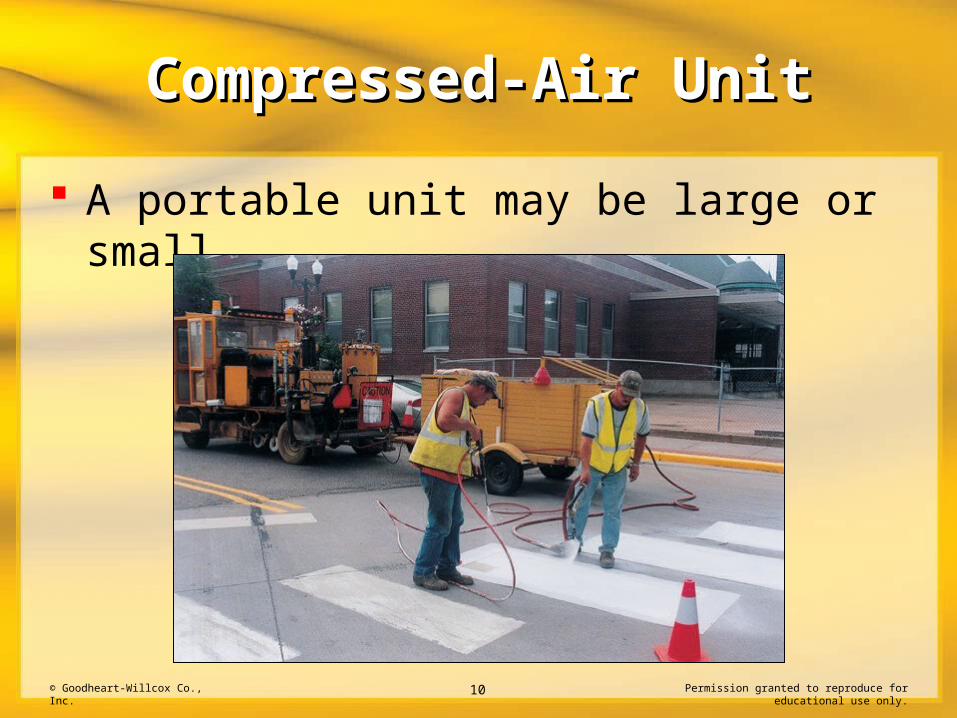
A portable unit may be large or small

© Goodheart-Willcox Co., Inc. Permission granted to reproduce for educational use only.11
Compressed-Air UnitCompressed-Air Unit
Portable units allow the compressor to be moved to the work site
Atlas Copco
© Goodheart-Willcox Co., Inc. Permission granted to reproduce for educational use only.12
Compressed-Air UnitCompressed-Air Unit
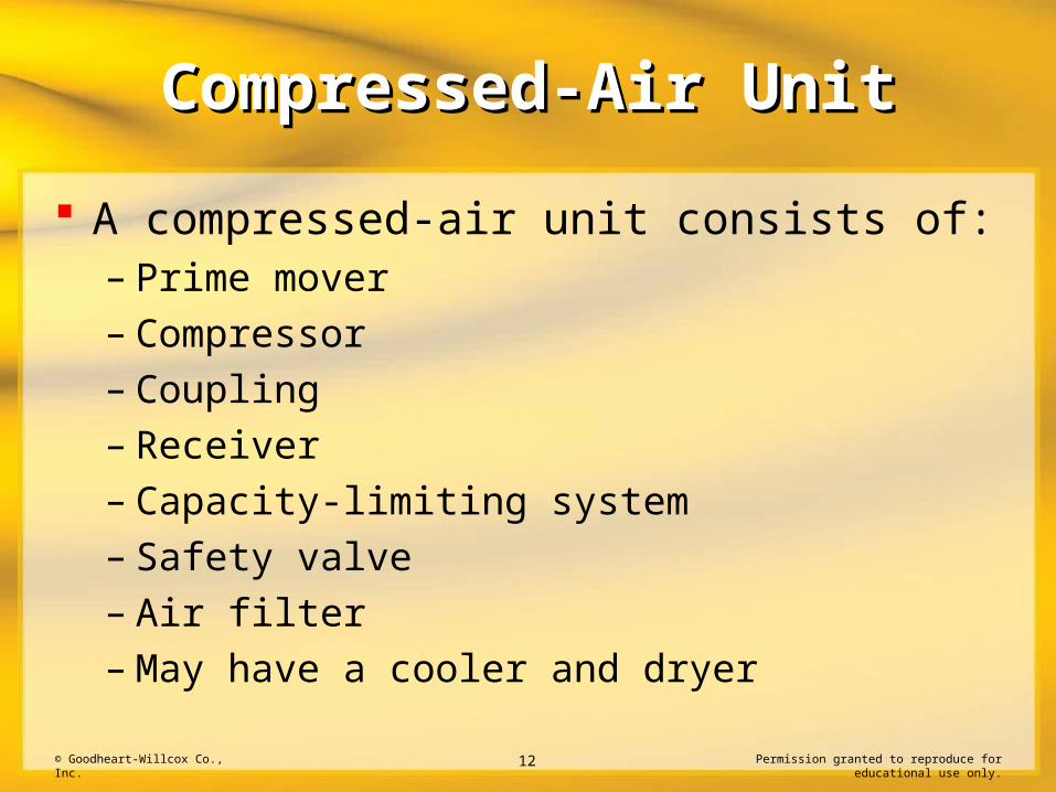
A compressed-air unit consists of:– Prime mover– Compressor– Coupling– Receiver– Capacity-limiting system– Safety valve– Air filter– May have a cooler and dryer

© Goodheart-Willcox Co., Inc. Permission granted to reproduce for educational use only.13
Compressed-Air UnitCompressed-Air Unit
The prime mover in a compressed-air unit may be:– Electric motor– Internal combustion engine– Steam or gas turbine
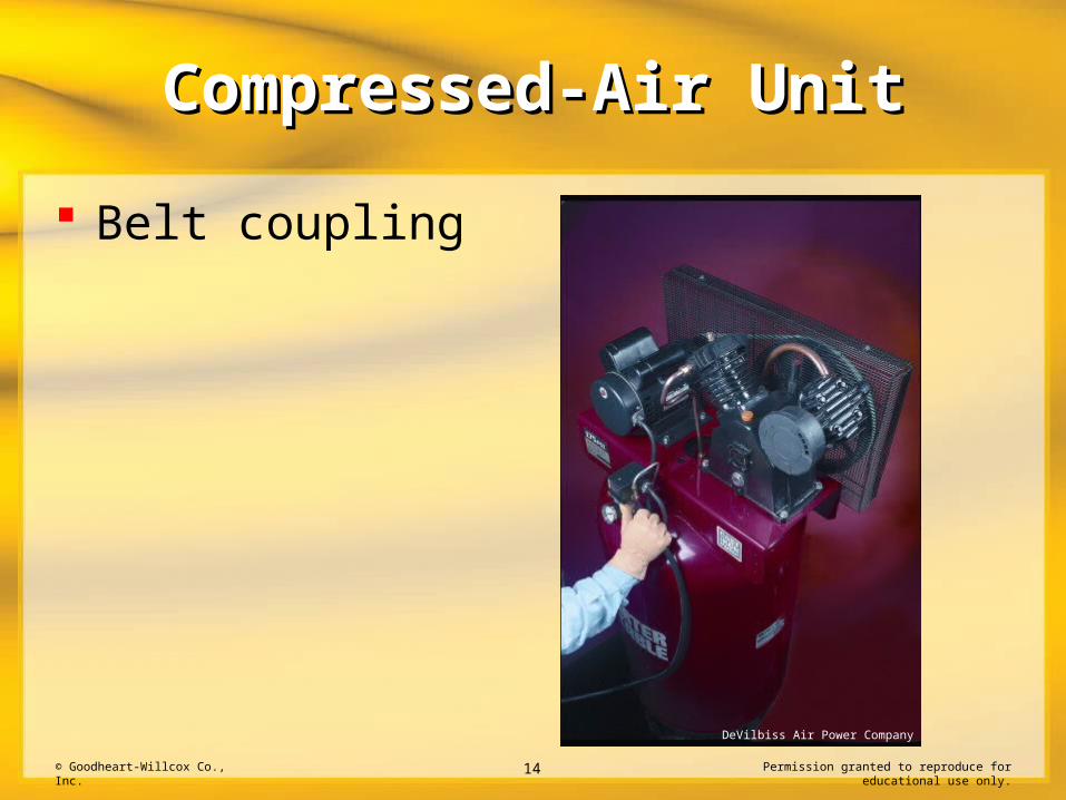
A coupling connects the prime mover to the compressor
© Goodheart-Willcox Co., Inc. Permission granted to reproduce for educational use only.14
Compressed-Air UnitCompressed-Air Unit
Belt coupling
DeVilbiss Air Power Company
© Goodheart-Willcox Co., Inc. Permission granted to reproduce for educational use only.15
Compressed-Air UnitCompressed-Air Unit
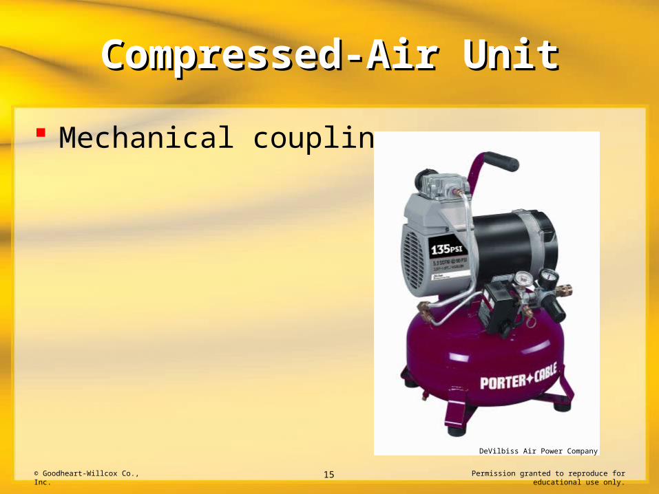
Mechanical coupling
DeVilbiss Air Power Company

© Goodheart-Willcox Co., Inc. Permission granted to reproduce for educational use only.16
Basic Compressor Basic Compressor DesignDesign
A variety of designs are used for air compressors in the compressed-air unit– Reciprocating piston– Rotary, sliding vane– Rotary screw– Dynamic

© Goodheart-Willcox Co., Inc. Permission granted to reproduce for educational use only.17
Basic Compressor Basic Compressor DesignDesign
Reciprocating-piston compressors are the most common
Rotary screw compressors are popular in new installations

© Goodheart-Willcox Co., Inc. Permission granted to reproduce for educational use only.18
Basic Compressor Basic Compressor DesignDesign
Inline, reciprocating compressor
DeVilbiss Air Power Company

© Goodheart-Willcox Co., Inc. Permission granted to reproduce for educational use only.19
Basic Compressor Basic Compressor DesignDesign
The basic operation of any compressor includes three phases– Air intake– Air compression– Air discharge
Component parts and physical operation varies between compressor designs

© Goodheart-Willcox Co., Inc. Permission granted to reproduce for educational use only.20
Basic Compressor Basic Compressor ClassificationsClassifications
Compressors are classified as:– Positive or non-positive displacement– Reciprocating or rotary
Positive-displacement compressors mechanically reduce the compression chamber size to achieved compression
Non-positive-displacement compressors use air velocity to increase pressure

© Goodheart-Willcox Co., Inc. Permission granted to reproduce for educational use only.21
Basic Compressor Basic Compressor ClassificationsClassifications
A reciprocating compressor has a positive displacement
DeVilbiss Air Power Company
© Goodheart-Willcox Co., Inc. Permission granted to reproduce for educational use only.22
Compressor Design and Compressor Design and OperationOperation
Reciprocating compressors use a cylinder and a reciprocating piston to achieve compression
Rotary compressors use continuously rotating vanes, screws, or lobed impellers to move and compress the air

© Goodheart-Willcox Co., Inc. Permission granted to reproduce for educational use only.23
Compressor Design and Compressor Design and OperationOperation
Reciprocating compressors are commonly used in pneumatic systems– Very small, single-cylinder, portable compressors
for consumer use– Large, industrial, stationary units may produce
thousands of cubic feet of compressed air per minute

© Goodheart-Willcox Co., Inc. Permission granted to reproduce for educational use only.24
Compressor Design and Compressor Design and OperationOperation
Large, industrial, reciprocating compressor
Atlas Copco

© Goodheart-Willcox Co., Inc. Permission granted to reproduce for educational use only.25
Compressor Design and Compressor Design and OperationOperation
Reciprocating compressors are available in single- or multiple-cylinder designs
Multiple cylinders may be arranged as:– Inline– Opposed– V type– W type– Other cylinder configuration

© Goodheart-Willcox Co., Inc. Permission granted to reproduce for educational use only.26
Compressor Design and Compressor Design and OperationOperation
Inline reciprocating compressor
DeVilbiss Air Power Company

© Goodheart-Willcox Co., Inc. Permission granted to reproduce for educational use only.27
Compressor Design and Compressor Design and OperationOperation
V-type reciprocating compressor
DeVilbiss Air Power Company

© Goodheart-Willcox Co., Inc. Permission granted to reproduce for educational use only.28
Compressor Design and Compressor Design and OperationOperation
Reciprocating compressors use a single-acting or double-acting compression arrangement– Single-acting compressors compress air during one
direction of piston travel– Double-acting compressors have two compression
chambers, allowing compression on both extension and retraction of the piston

© Goodheart-Willcox Co., Inc. Permission granted to reproduce for educational use only.29
Compressor Design and Compressor Design and OperationOperation
Double-acting compressor

© Goodheart-Willcox Co., Inc. Permission granted to reproduce for educational use only.30
Compressor Design and Compressor Design and OperationOperation
Rotary, sliding-vane compressors use a slotted rotor containing movable vanes to compress air– Rotor is placed off center in a circular compression
chamber, allowing the chamber volume to change during rotation
– These volume changes allow the intake, compression, and discharge of air during compressor rotation

© Goodheart-Willcox Co., Inc. Permission granted to reproduce for educational use only.31
Compressor Design and Compressor Design and OperationOperation
Centrifugal force keeps the vanes in contact with the walls

© Goodheart-Willcox Co., Inc. Permission granted to reproduce for educational use only.32
Compressor Design and Compressor Design and OperationOperation
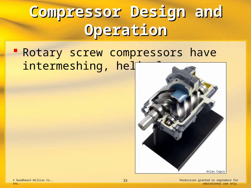
Rotary screw compressors use intermeshing, helical screws to form chambers that move air from the atmosphere into the system on a continuous basis
This produces a nonpulsating flow of air at the desired pressure level
© Goodheart-Willcox Co., Inc. Permission granted to reproduce for educational use only.33
Compressor Design and Compressor Design and OperationOperation
Rotary screw compressors have intermeshing, helical screws
Atlas Copco
© Goodheart-Willcox Co., Inc. Permission granted to reproduce for educational use only.34
Compressor Design and Compressor Design and OperationOperation
Rotary screw compressors have become popular for larger industrial installations– Lower initial cost– Lower maintenance cost– Adaptable to sophisticated electronic control
systems
© Goodheart-Willcox Co., Inc. Permission granted to reproduce for educational use only.35
Compressor Design and Compressor Design and OperationOperation
Sliding vane and screw compressor designs often inject oil into the airstream moving through the compressors– Reduces wear on vane and screw contact surfaces– Improves the seal between the surfaces
Oil is removed by a separator to provide near-oilless compressed air for the pneumatic system

© Goodheart-Willcox Co., Inc. Permission granted to reproduce for educational use only.36
Compressor Design and Compressor Design and OperationOperation
The basic operating theory of dynamic compressors is converting the kinetic energy of high-speed air into pressure
Dynamic compressor designs are either:– Centrifugal– Axial

© Goodheart-Willcox Co., Inc. Permission granted to reproduce for educational use only.37
Compressor Design and Compressor Design and OperationOperation
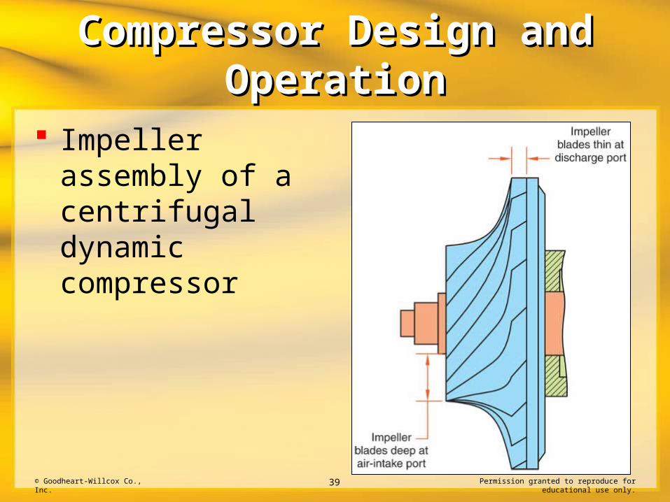
Centrifugal dynamic compressor:– An impeller increases airspeed– Prime mover energy is converted into kinetic
energy as airspeed rapidly increases through the impeller
– Kinetic energy is converted to air pressure as air movement slows in the volute collector

© Goodheart-Willcox Co., Inc. Permission granted to reproduce for educational use only.38
Compressor Design and Compressor Design and OperationOperation
Centrifugal dynamic compressor
© Goodheart-Willcox Co., Inc. Permission granted to reproduce for educational use only.39
Compressor Design and Compressor Design and OperationOperation
Impeller assembly of a centrifugal dynamic compressor

© Goodheart-Willcox Co., Inc. Permission granted to reproduce for educational use only.40
Compressor Design and Compressor Design and OperationOperation
Axial-flow dynamic compressor:– Rotating rotor blades increase airspeed– Fixed stator blades decrease airspeed– Kinetic energy is converted to air pressure– Series of rotor and stator sections are staged
to form the axial-flow compressor

© Goodheart-Willcox Co., Inc. Permission granted to reproduce for educational use only.41
Compressor Design and Compressor Design and OperationOperation
Axial-flow dynamic compressor

© Goodheart-Willcox Co., Inc. Permission granted to reproduce for educational use only.42
Compressor Design and Compressor Design and OperationOperation
Pressure is created when high-speed air is slowed by the fixed stator blades

© Goodheart-Willcox Co., Inc. Permission granted to reproduce for educational use only.43
Compressor Design and Compressor Design and OperationOperation
Dynamic compressor designs are used to compress air and other gases for large, industrial applications– Oil refineries– Chemical plants– Steel mills

© Goodheart-Willcox Co., Inc. Permission granted to reproduce for educational use only.44
Compressor Design and Compressor Design and OperationOperation
Lobe-type compressors consist of two impellers with two or three lobes that operate in an elongated chamber in the compressor body– Spinning impellers trap air in chambers that form
between the lobes– As the impellers turn, this trapped air is swept from
the inlet port to the outlet port to increase system pressure

© Goodheart-Willcox Co., Inc. Permission granted to reproduce for educational use only.45
Compressor Design and Compressor Design and OperationOperation
Impellers from a lobe-type compressor
Atlas Copco

© Goodheart-Willcox Co., Inc. Permission granted to reproduce for educational use only.46
Compressor Design and Compressor Design and OperationOperation
Lobe-type compressors are often called blowers They are typically used in applications
requiring air pressure of only 10 to 20 psi

© Goodheart-Willcox Co., Inc. Permission granted to reproduce for educational use only.47
Compressor Design and Compressor Design and OperationOperation
Compressor staging involves connecting a number of basic compressor units in series to raise air pressure in small increments
This method permits easier control of air temperature, which results in more-efficient compressor package operation

© Goodheart-Willcox Co., Inc. Permission granted to reproduce for educational use only.48
Compressor Design and Compressor Design and OperationOperation
Inline, staged, reciprocating compressor
DeVilbiss Air Power Company

© Goodheart-Willcox Co., Inc. Permission granted to reproduce for educational use only.49
Compressor-Capacity Compressor-Capacity ControlControl
Compressor-capacity control refers to the system that matches the compressed-air output to the system-air demand
The better the air output of the compressor matches system consumption, the more cost effective the operation of the system
© Goodheart-Willcox Co., Inc. Permission granted to reproduce for educational use only.50
Compressor-Capacity Compressor-Capacity ControlControl
Compressor-capacity control systems include:– Bypass– Start-stop– Inlet valve unloading– Speed variation– Inlet size variation

© Goodheart-Willcox Co., Inc. Permission granted to reproduce for educational use only.51
Compressor-Capacity Compressor-Capacity ControlControl
Bypass control uses a relief-type valve to exhaust excess air
Air is continuously delivered to the system at the compressor’s maximum flow rate
This type of control is not considered desirable as it is inefficient

© Goodheart-Willcox Co., Inc. Permission granted to reproduce for educational use only.52
Compressor-Capacity Compressor-Capacity ControlControl
Start-stop capacity control is commonly used with small, electric motor-driven compressor packages that operate pneumatic systems consuming air on an intermittent basis

© Goodheart-Willcox Co., Inc. Permission granted to reproduce for educational use only.53
Compressor-Capacity Compressor-Capacity ControlControl
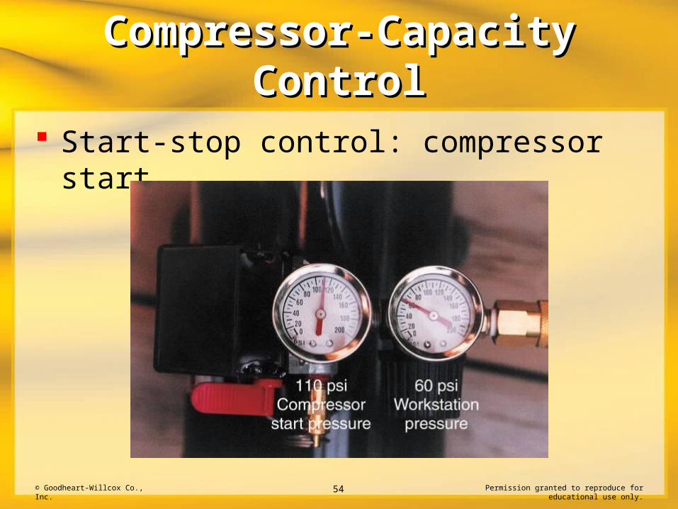
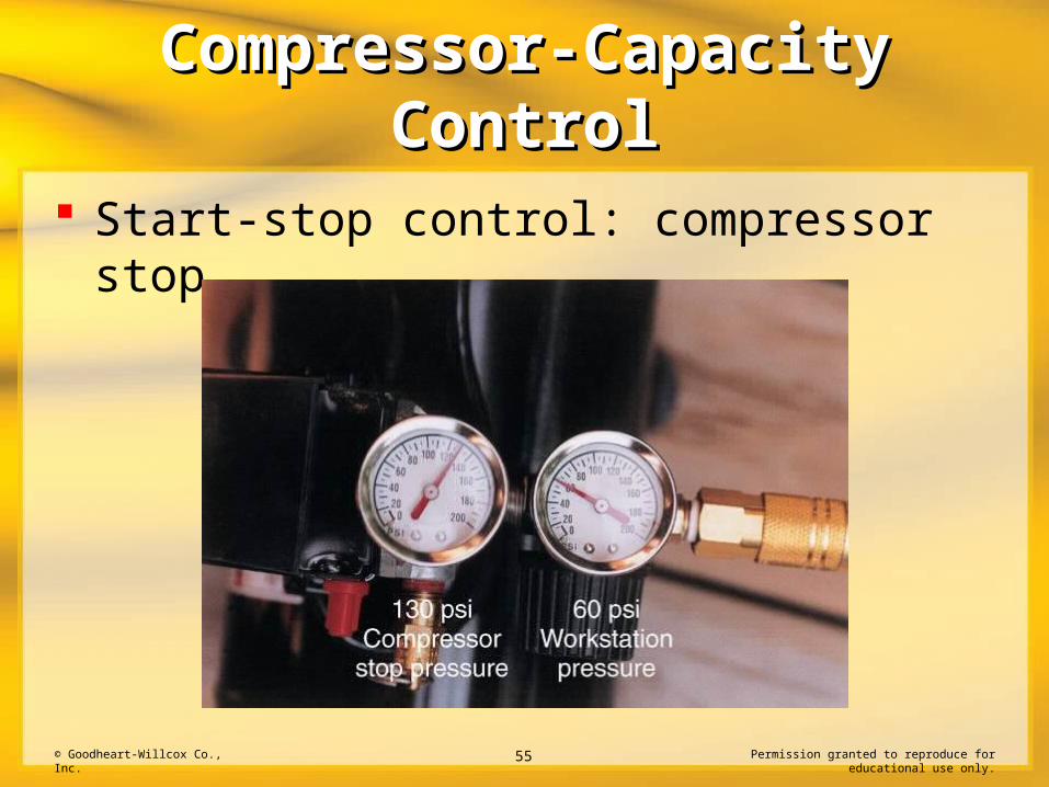
Start-stop control uses a pressure-sensitive switch to start and stop the compressor to maintain a preselected pressure range
© Goodheart-Willcox Co., Inc. Permission granted to reproduce for educational use only.54
Compressor-Capacity Compressor-Capacity ControlControl
Start-stop control: compressor start
© Goodheart-Willcox Co., Inc. Permission granted to reproduce for educational use only.55
Compressor-Capacity Compressor-Capacity ControlControl
Start-stop control: compressor stop
© Goodheart-Willcox Co., Inc. Permission granted to reproduce for educational use only.56
Compressor-Capacity Compressor-Capacity ControlControl
Inlet valve unloading controls compressor output by holding the inlet valve open whenever maximum system pressure is achieved– Allows the prime mover to operate continuously– Can be used in systems having internal combustion
engines or electric motors as the prime mover
© Goodheart-Willcox Co., Inc. Permission granted to reproduce for educational use only.57
Compressor-Capacity Compressor-Capacity ControlControl
Varying compressor speed can control compressor capacity– Can be used with reciprocating and rotary
compressor designs– Primarily used on large, industrial installations– Sensors monitor pressure and send a signal to
control compressor speed

© Goodheart-Willcox Co., Inc. Permission granted to reproduce for educational use only.58
Compressor-Capacity Compressor-Capacity ControlControl
Varying the size of the compressor inlet can control compressor capacity– Compressor operates at a constant speed– The volume of air that can enter the compressor is
restricted– Output varies with the size of the inlet– Primarily used on dynamic compressors

© Goodheart-Willcox Co., Inc. Permission granted to reproduce for educational use only.59
Selecting a Compressor Selecting a Compressor PackagePackage
Establishing the level of system air consumption is a key factor when selecting a compressor
This can be accomplished by identifying:– Actuators used in the system– Compressed-air needs of each item– Percentage of time each functions
© Goodheart-Willcox Co., Inc. Permission granted to reproduce for educational use only.60
Selecting a Compressor Selecting a Compressor PackagePackage
Other factors must be considered during system compressor selection– Compressor and prime mover type– Method of compressor-capacity control– Auxiliary controls such as coolers, separators, and
driers
System instrumentation

© Goodheart-Willcox Co., Inc. Permission granted to reproduce for educational use only.61
Review QuestionReview Question
Compressed-air units may be classified as a(n) _____ or _____.
portable unit; central air supply

© Goodheart-Willcox Co., Inc. Permission granted to reproduce for educational use only.62
Review QuestionReview Question
List the components found in a typical compressed-air unit and describe their function.
A. Prime mover to supply system energy; B. coupling to mechanically connect prime mover and compressor; C. compressor to pressurize atmospheric air; D. receiver to store conditioned air; E. capacity-limiting switch to limit the maximum pressure produced by the compressor; F. safety valve to vent pressure if the capacity-limiting switch fails; and G. may also include filters, coolers, and dryers.

© Goodheart-Willcox Co., Inc. Permission granted to reproduce for educational use only.63
Review QuestionReview Question
The simplest compressor in both design and operating theory is the single-acting, _____ compressor.
reciprocating

© Goodheart-Willcox Co., Inc. Permission granted to reproduce for educational use only.64
Review QuestionReview Question
Dynamic compressors can also be classified as _____-displacement compressors.
non-positive

© Goodheart-Willcox Co., Inc. Permission granted to reproduce for educational use only.65
Review QuestionReview Question
The continuous rotating motion of the compression elements identifies a(n) _____ compressor design.
rotary
© Goodheart-Willcox Co., Inc. Permission granted to reproduce for educational use only.66
Review QuestionReview Question
Describe the double-acting compressor design.
A connecting rod and crosshead are used to convert the rotary motion of the crankshaft to the reciprocating motion. Compression chambers on either side of the piston allow compression and intake during each piston stroke.

© Goodheart-Willcox Co., Inc. Permission granted to reproduce for educational use only.67
Review QuestionReview Question
In a two-stage, reciprocating compressor, the outlet port of the first compression chamber is connected to the _____ port of a second compression chamber.
inlet

© Goodheart-Willcox Co., Inc. Permission granted to reproduce for educational use only.68
Review QuestionReview Question
Compressor-air output and system-air demand are matched by using some type of _____ system.
compressor-capacity control
© Goodheart-Willcox Co., Inc. Permission granted to reproduce for educational use only.69
Review QuestionReview Question
Name four factors that make selecting a compressor difficult.
A. The variety of compressor designs, B. load variations in a pneumatic system, C. the variety of auxiliary equipment available, and D. demands of future growth of the system.