Embed Size (px)
Citation preview
Chapter 14Registering Multimodal Imagery with OccludingObjects Using Mutual Information: Applicationto Stereo Tracking of Humans
Stephen Krotosky and Mohan Trivedi
Abstract This chapter introduces and analyzes a method for registering multimodalimages with occluding objects in the scene. An analysis of multimodal image regis-tration gives insight into the limitations of assumptions made in current approachesand motivates the methodology of the developed algorithm. Using calibrated stereoimagery, we use maximization of mutual information in sliding correspondencewindows that inform a disparity voting algorithm to demonstrate successful reg-istration of objects in color and thermal imagery where there is significant occlu-sion. Extensive testing of scenes with multiple objects at different depths and levelsof occlusion shows high rates of successful registration. Ground truth experimentsdemonstrate the utility of disparity voting techniques for multimodal registrationby yielding qualitative and quantitative results that outperform approaches that donot consider occlusions. A framework for tracking with the registered multimodalfeatures is also presented and experimentally validated.
Keywords: Multimodal stereo · Person detection/tracking · Visual surveillance ·Infrared imaging
14.1 Introduction
Computer vision applications are increasingly using multimodal imagery to obtainand process information about a scene. Specifically, the disparate yet complemen-tary nature of visual and thermal imagery has been used in recent works to obtainadditional information and robustness [1,2]. The use of both types of imagery yieldsinformation about the scene that is rich in color, depth, motion, and thermal detail.Such information can then be used to successfully detect, track, and analyze peopleand objects in the scene.
To associate the information from each modality, corresponding data in eachimage must be successfully registered. In long-range surveillance applications [2],the cameras are assumed to be oriented in such a way that a global alignment
R.I. Hammoud (ed.), Augmented Vision Perception in Infrared: Algorithms and 321Applied Systems, Advances in Pattern Recognition,c© Springer-Verlag London Limited 2009
DOI 10.1007/978-1-84800-277-7 14,
322 S. Krotosky and M. Trivedi
function will register all objects in the scene. However, this assumption means thatthe camera must be very far away from the imaged scene. When analysis of nearerscenes is desired or necessary, the global alignment will not hold.
A minimum camera solution for registering multimodal imagery in these short-range surveillance situations would be to use a single camera from each modality,arranged in a stereo pair. Unlike colocating the cameras, arranging the cameras into astereo pair allows objects at different depths to be registered. The stereo registrationwould occur on a local level, similar to the way unimodal stereo camera approachesgive local registration for the left and right camera pairs. However, because of thedisparate nature of the imagery, conventional stereo correspondence-matching as-sumptions do not hold, and care needs to be taken to ensure reliable registration ofobjects in the scene.
One fundamental approach to multimodal stereo registration is to utilize mutualinformation to assign correspondence values to the scene. Egnal has shown that mu-tual information is a viable similarity metric for multimodal stereo registration whenthe mutual information window sizes are large enough to sufficiently populate thejoint probability histogram of the mutual information computation [3]. An approachby Chen et al. [4] sought to obtain these large window regions by assuming thatbounding boxes (BBs) could be extracted and tracked for each object in the scene.When the assumption that segmentation and tracking of each BB is perfect, thegiven regions can provide for accurate registration. However, in practice, it is oftendifficult to obtain these necessary tracking results when there are occluding objectsin the scene. In these occlusion cases, segmentation often gives BBs consisting oftwo or more merged objects, and the BB approach will not be able to successfullyregister the objects in the merged BB.
This chapter introduces an approach to registering multimodal imagery that isable to accurately register occluding objects at different disparities in the scene.A disparity voting (DV) technique that uses the accumulation of disparity valuesfrom sliding correspondence windows gives reliable and robust registration resultsfor initial segmentations that can include occluding objects. This approach requiresno prior assumptions about pixel ownership or tracking. Analysis of several thou-sand frames demonstrated the success of our registration algorithm for complexscenes with high levels of occlusion and numbers of objects occupying the imagedspace. Experiments using both ground truth and practical segmentation illustratedhow the occlusion handling of the DV algorithm is an improvement over previousapproaches. A framework for tracking with the registered multimodal features isalso presented and experimentally validated.
14.2 Related Research
Many of the previous works in multimodal image registration have addressed theregistration problem by assuming that a global transformation model exists that willregister all the objects in the scene. Davis and Sharma [2], as well as O’Conaire
14 Registration Multimodal Imagery 323
et al. [5], used an infinite planar homography assumption to perform registration.Under this assumption, the imaged scene will be very far from the camera, so that anobject’s displacement from the registered ground plane will be negligible comparedto the observation distance. While this is appropriate for long-distance and overheadsurveillance scenes, it is not valid when objects can be at various depths and theirdifference is significant relative to their distance from the camera.
Other global image registration methods assume that all registered objects will lieon a single plane in the image. It is impossible to accurately register objects at dif-ferent observation depths under this assumption as the displacement and scaling foreach object will depend on the varying perspective effects of the camera. This meansthat accurate registration can only occur when there is only one observed object inthe scene [6] or when all the observed objects are restricted to lie at approximatelythe same distance from the camera [7]. The global alignment algorithms proposedby Irani & Anandan [8] and Coiras et al. [9] do not account or experiment whenthere are objects at different depths or in different planes in the image. Both utilizethe assumption that the colocation of the cameras and the observed distances aresuch that the parallax effects can be ignored.
Multiple stereo camera approaches have been investigated by Bertozzi et al. [1].They used four cameras configured into two unimodal stereo pairs that yielded twoseparate disparity estimates. Registration can then occur in the disparity domain.While this approach yields redundancy and registration success, the use of four cam-eras can be cumbersome in physical creation, calibration, and management, as wellas in data storage and processing. A registration solution using the minimum (2)number of cameras is desired.
Chen et al. [4] introduced the idea of registering partial image regions of interestinstead of finding a global transformation. The main assumption of this approachis that each BB region of interest corresponds to a single object in the scene and isat a specific plane that can be individually registered with a separate homography.They proposed that the imagery can be registered using a maximization of mutualinformation technique on BB that correspond to detected and tracked objects in oneof the modalities. The matching BB is then searched over the other modality. EachBB is independently matched so that multiple objects at different depths can beregistered.
However, a limiting requirement of this approach is that BBs can always beproperly segmented and tracked in one of the modalities so that the correspondingregion can be identified using the maximization of mutual information technique.While [10] relaxed this somewhat by proposing an initial silhouette extraction forBB construction, the assumption that the BBs will be properly segmented will of-ten not hold, especially when occlusions can produce BBs that contain two or moremerged objects at different depths. Objects will not be registered properly whenusing BBs that contain multiple objects as the required assumption that a BB is con-tained within a single plane will not hold. In addition, Chen et al. did not actuallypresent any registration results where there are objects that are at significantly dif-ferent depths in the scene or situations where occlusions or improperly formed BBsare an issue.
324 S. Krotosky and M. Trivedi
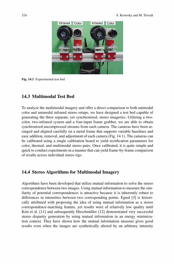
Fig. 14.1 Experimental test bed
14.3 Multimodal Test Bed
To analyze the multimodal imagery and offer a direct comparison to both unimodalcolor and unimodal infrared stereo setups, we have designed a test bed capable ofgenerating the three separate, yet synchronized, stereo imageries. Utilizing a two-color, two-infrared system and a four-input frame grabber, we are able to obtainsynchronized uncompressed streams from each camera. The cameras have been ar-ranged and aligned carefully on a metal frame that supports variable baselines andeasy addition, removal, and adjustment of each camera (Fig. 14.1). The cameras canbe calibrated using a single calibration board to yield rectification parameters forcolor, thermal, and multimodal stereo pairs. Once calibrated, it is quite simple andquick to conduct experiments in a manner that can yield frame-by-frame comparisonof results across individual stereo rigs.
14.4 Stereo Algorithms for Multimodal Imagery
Algorithms have been developed that utilize mutual information to solve the stereocorrespondence between two images. Using mutual information to measure the sim-ilarity of potential correspondences is attractive because it is inherently robust todifferences in intensities between two corresponding points. Egnal [3] is histori-cally attributed with proposing the idea of using mutual information as a stereocorrespondence-matching feature, yet results were of relatively low quality untilKim et al. [11] and subsequently Hirschmuller [12] demonstrated very successfulstereo disparity generation by using mutual information in an energy minimiza-tion context. They have shown how the mutual information measure gives goodresults even when the images are synthetically altered by an arbitrary intensity
14 Registration Multimodal Imagery 325
transformation. We investigate whether these mutual information-based stereo al-gorithms can resolve the correspondence problem for true multimodal imagery withthe same success achieved for synthetically altered imagery.
We chose to utilize the algorithm developed by Hirschmuller [12] in analyzingthe use of mutual information with energy minimization for solving multimodalstereo correspondences. This choice was based on the fact that this algorithm is themutual information-based approach that performed best on the Middlebury CollegeStereo Evaluation [13]. Its use of mutual information is identical to that of Kim et al.. [11], and the two algorithms differ only in how the energy function is minimized,with Kim et al. using the global optimization of graph cuts, while Hirschmullerutilized a faster hierarchical approach called semiglobal matching.
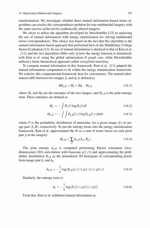
To compute mutual information in this framework, Kim et al. [11] adapted themutual information computation to fit within the energy minimization framework.We rederive this computational framework here for convenience. The mutual infor-mation (MI) between two images IL and IR is defined as
MIL,R = HL +HR−HL,R (14.1)
where HL and HR are the entropies of the two images, and HL,R is the joint entropyterm. These entropies are defined as
HL = −∫
PL(l) logPL(l)dl (14.2)
HL,R = −∫ ∫
PL,R(l,r) logPL,R(l,r)dldr (14.3)
where P is the probability distribution of intensities for a given image (L) or im-age pair (L,R), respectively. To put the entropy terms into the energy minimizationframework, Kim et al. approximated the H as a sum of terms based on each pixelpair p in the imagery:
HL,R =∑p
hL,R(Lp,Rp) (14.4)
The joint entropy hL,R is computed performing Parzen estimation [two-dimensional (2D) convolution with Gaussian g(l,r)] and approximating the prob-ability distribution PL,R as the normalized 2D histogram of corresponding pixelsfrom image pair IL and IR.
hL,R =−1n
log(PL,R(l,r)⊗g(l,r))⊗g(l,r) (14.5)
Similarly, the entropy term is:
hL =−1n
log(PL(l)⊗g(l))⊗g(l) (14.6)
From this, Kim et al. redefined mutual information as:
326 S. Krotosky and M. Trivedi
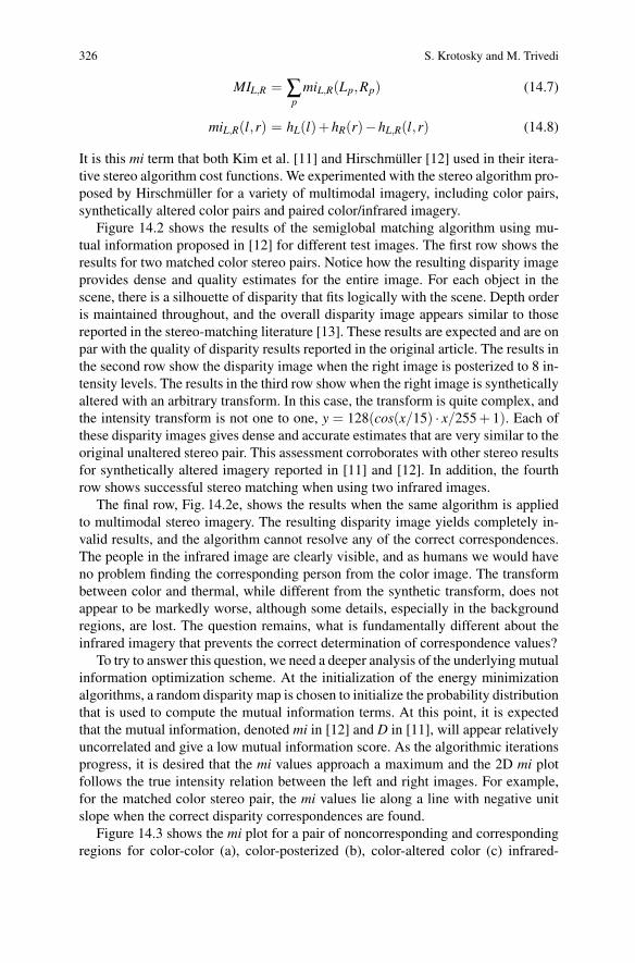
MIL,R =∑p
miL,R(Lp,Rp) (14.7)
miL,R(l,r) = hL(l)+hR(r)−hL,R(l,r) (14.8)
It is this mi term that both Kim et al. [11] and Hirschmuller [12] used in their itera-tive stereo algorithm cost functions. We experimented with the stereo algorithm pro-posed by Hirschmuller for a variety of multimodal imagery, including color pairs,synthetically altered color pairs and paired color/infrared imagery.
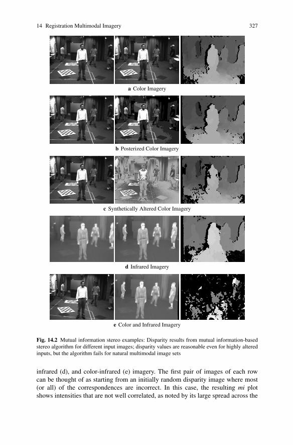
Figure 14.2 shows the results of the semiglobal matching algorithm using mu-tual information proposed in [12] for different test images. The first row shows theresults for two matched color stereo pairs. Notice how the resulting disparity imageprovides dense and quality estimates for the entire image. For each object in thescene, there is a silhouette of disparity that fits logically with the scene. Depth orderis maintained throughout, and the overall disparity image appears similar to thosereported in the stereo-matching literature [13]. These results are expected and are onpar with the quality of disparity results reported in the original article. The results inthe second row show the disparity image when the right image is posterized to 8 in-tensity levels. The results in the third row show when the right image is syntheticallyaltered with an arbitrary transform. In this case, the transform is quite complex, andthe intensity transform is not one to one, y = 128(cos(x/15) · x/255 + 1). Each ofthese disparity images gives dense and accurate estimates that are very similar to theoriginal unaltered stereo pair. This assessment corroborates with other stereo resultsfor synthetically altered imagery reported in [11] and [12]. In addition, the fourthrow shows successful stereo matching when using two infrared images.
The final row, Fig. 14.2e, shows the results when the same algorithm is appliedto multimodal stereo imagery. The resulting disparity image yields completely in-valid results, and the algorithm cannot resolve any of the correct correspondences.The people in the infrared image are clearly visible, and as humans we would haveno problem finding the corresponding person from the color image. The transformbetween color and thermal, while different from the synthetic transform, does notappear to be markedly worse, although some details, especially in the backgroundregions, are lost. The question remains, what is fundamentally different about theinfrared imagery that prevents the correct determination of correspondence values?
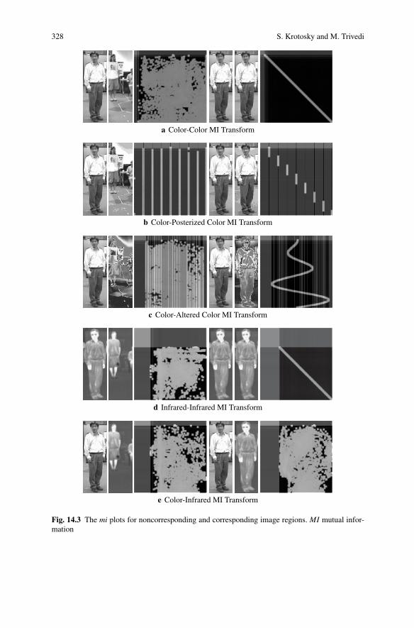
To try to answer this question, we need a deeper analysis of the underlying mutualinformation optimization scheme. At the initialization of the energy minimizationalgorithms, a random disparity map is chosen to initialize the probability distributionthat is used to compute the mutual information terms. At this point, it is expectedthat the mutual information, denoted mi in [12] and D in [11], will appear relativelyuncorrelated and give a low mutual information score. As the algorithmic iterationsprogress, it is desired that the mi values approach a maximum and the 2D mi plotfollows the true intensity relation between the left and right images. For example,for the matched color stereo pair, the mi values lie along a line with negative unitslope when the correct disparity correspondences are found.
Figure 14.3 shows the mi plot for a pair of noncorresponding and correspondingregions for color-color (a), color-posterized (b), color-altered color (c) infrared-
14 Registration Multimodal Imagery 327
a Color Imagery
b Posterized Color Imagery
c Synthetically Altered Color Imagery
d Infrared Imagery
e Color and Infrared Imagery
Fig. 14.2 Mutual information stereo examples: Disparity results from mutual information-basedstereo algorithm for different input images; disparity values are reasonable even for highly alteredinputs, but the algorithm fails for natural multimodal image sets
infrared (d), and color-infrared (e) imagery. The first pair of images of each rowcan be thought of as starting from an initially random disparity image where most(or all) of the correspondences are incorrect. In this case, the resulting mi plotshows intensities that are not well correlated, as noted by its large spread across the
328 S. Krotosky and M. Trivedi
a Color-Color MI Transform
b Color-Posterized Color MI Transform
c Color-Altered Color MI Transform
d Infrared-Infrared MI Transform
e Color-Infrared MI Transform
Fig. 14.3 The mi plots for noncorresponding and corresponding image regions. MI mutual infor-mation
14 Registration Multimodal Imagery 329
image 2D mi histogram. For the color-color, color-posterized, color-altered color,and infrared-infrared cases, when we choose corresponding image regions, the miplot shows the well-correlated image intensity transform, as expected. However,for the case of corresponding color-infrared images, the mi value does not reduceto some easily discernable transform. In fact, the intensities for the correspondingmultimodal regions appear just as uncorrelated as the intensities for the noncorre-sponding regions. This indicates that using these types of energy minimization algo-rithms is not possible with color and infrared stereo imagery. This uncorrelatednessof the color and thermal imagery means that it is difficult to predict the intensity ofan infrared pixel given a corresponding color intensity. Because of this, the use ofmutual information as an energy minimization term is not appropriate. The mutualinformation energy term (mi values) needs to be minimized, yet cannot be becausethe uncorrelation between color and thermal image intensities produces similarlylarge values for both good and bad matches.
14.5 Multimodal Stereo Using Primitive Matching
We have demonstrated that current state-of-the-art stereo algorithms cannot utilizemutual information to effectively solve the multimodal stereo correspondence prob-lem. It is important to now seek out alternative features and approaches that maygive some way of obtaining correspondences in the scene. To achieve any successin stereo correspondence matching with multimodal imagery, it is imperative to firstidentify features that are universal to both color and thermal imagery. While it isclear that there is little commonality associated with the intensities across colorand thermal imagery, the example multimodal stereo pair in Fig. 14.2e suggests thatthere is some clear commonality on a regional (object) level and on edges associ-ated with these region boundaries. For example, skin tone regions in the color imagecorrespond well to bright intensity regions on the infrared image. In general, the sil-houettes associated with the people in the scene have similar sizes, shapes, and edgeboundaries in each modality.
Resolving stereo correspondences through regions is one of the classical ap-proaches to utilizing image features for image matching. Traditionally, works suchas those by Marapane and Trivedi [14] and Cohen et al. [15] use image segmenta-tion to obtain regions and can achieve a coarse disparity estimate. Usually, this sortof approach is one part of a larger stereo-matching algorithm with the coarse dis-parity map used to guide refinements at finer detail. More recently, approaches thatuse the concept of oversegmentation have been applied to stereo imagery [16, 17].By oversegmenting the image into very small regions, matching can be done ina progressive manner similar to pixel-based energy minimization functions. Theseoversegmentation approaches rely on the intensity similarity properties of unimodalstereo imagery and are therefore not readily extendable to the multimodal case.The challenge in applying region-based approaches to multimodal imagery lies in
330 S. Krotosky and M. Trivedi
finding region segmentation that yields small enough regions to allow for a fine levelof disparities while maintaining large enough regions to allow for reliable and robustmatching.
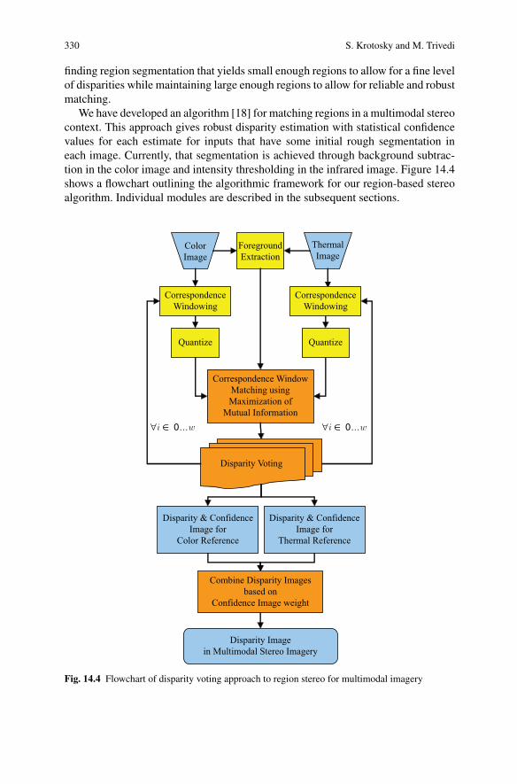
We have developed an algorithm [18] for matching regions in a multimodal stereocontext. This approach gives robust disparity estimation with statistical confidencevalues for each estimate for inputs that have some initial rough segmentation ineach image. Currently, that segmentation is achieved through background subtrac-tion in the color image and intensity thresholding in the infrared image. Figure 14.4shows a flowchart outlining the algorithmic framework for our region-based stereoalgorithm. Individual modules are described in the subsequent sections.
ColorImage
ThermalImage
Quantize
Correspondence WindowMatching usingMaximization of
Mutual Information
Quantize
CorrespondenceWindowing
CorrespondenceWindowing
Disparity & ConfidenceImage for
Color Reference
Combine Disparity Imagesbased on
Confidence Image weight
Disparity Imagein Multimodal Stereo Imagery
ForegroundExtraction
Disparity & ConfidenceImage for
Thermal Reference
∀i ∈ 0...w ∀i ∈ 0...w
Disparity Voting
Fig. 14.4 Flowchart of disparity voting approach to region stereo for multimodal imagery
14 Registration Multimodal Imagery 331
a Color b Color Segmenta-tion
c Infrared d Infrared Seg-mentation
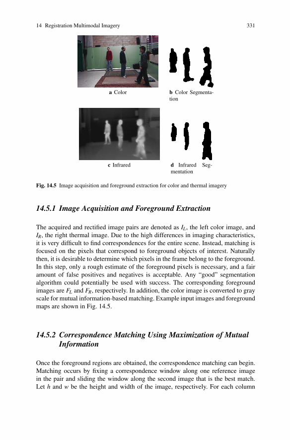
Fig. 14.5 Image acquisition and foreground extraction for color and thermal imagery
14.5.1 Image Acquisition and Foreground Extraction
The acquired and rectified image pairs are denoted as IL, the left color image, andIR, the right thermal image. Due to the high differences in imaging characteristics,it is very difficult to find correspondences for the entire scene. Instead, matching isfocused on the pixels that correspond to foreground objects of interest. Naturallythen, it is desirable to determine which pixels in the frame belong to the foreground.In this step, only a rough estimate of the foreground pixels is necessary, and a fairamount of false positives and negatives is acceptable. Any “good” segmentationalgorithm could potentially be used with success. The corresponding foregroundimages are FL and FR, respectively. In addition, the color image is converted to grayscale for mutual information-based matching. Example input images and foregroundmaps are shown in Fig. 14.5.
14.5.2 Correspondence Matching Using Maximization of MutualInformation
Once the foreground regions are obtained, the correspondence matching can begin.Matching occurs by fixing a correspondence window along one reference imagein the pair and sliding the window along the second image that is the best match.Let h and w be the height and width of the image, respectively. For each column
332 S. Krotosky and M. Trivedi
i ∈ 0, . . . ,w, let WL,i be a correspondence window in the left image of height h andwidth M centered on column i. The width M that produces the best results can beexperimentally determined for a given scene. Typically, the value for M is signifi-cantly less than the width of an object in the scene. Define a correspondence windowWR,i,d in the right image having height h∗, the largest spanning foreground distancein the correspondence window, and centered at a column i+d, where d is a disparityoffset. For each column i, a correspondence value is found for all d ∈ dmin, . . . ,dmax.
Given the two correspondence windows WL,i and WR,i,d , we first linearly quantizethe image to N levels such that
N ≈√
Mh∗/8 (14.9)
where Mh∗ is the area of the correspondence window. The result in (14.9) comesfrom Thevenaz and Unser’s [19] suggestion that this equation is reasonable to de-termine the number of levels needed to give good results for maximizing the mutualinformation between image regions.
Now, we can compute the quality of the match between the two correspondencewindows by measuring the mutual information between them. We define the mutualinformation between two specific image patches as MIi,d where again i is the centerof the reference correspondence window, and i + d is the center of the second cor-respondence window. For each column i, we have a mutual information value MIi,dfor d ∈ dmin, . . . ,dmax. The disparity d∗i that best matches the two windows is theone that maximizes the mutual information:
d∗i = argmaxd
MIi,d (14.10)
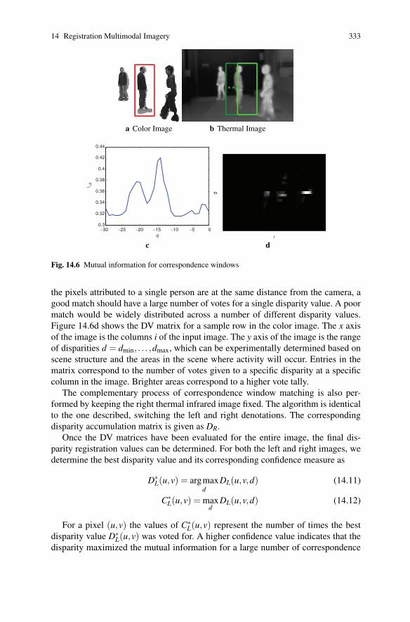
The process of computing the mutual information for a specific correspondencewindow is illustrated in Fig. 14.6. An example plot of the mutual information val-ues over the range of disparities is also shown. The red box in the color image isa visualization of a potential reference correspondence window. Candidate slidingcorrespondence windows for the thermal image are visualized in green boxes.
14.5.3 Disparity Voting with Sliding Correspondence Windows
We wish to assign a vote for d∗i , the disparity that maximizes the mutual informa-tion, to all foreground pixels in the reference correspondence window. Define a DVmatrix DL of size (h,w,dmax−dmin +1), the range of disparities. Then, given a col-umn i, for each image pixel that is in the correspondence window and foregroundmap, (u,v) ∈ (WL,i ∩ FL), we add to the DV matrix at DL(u,v,d∗i ).
Since the correspondence windows are M pixels wide, pixels in each column inthe image will have M votes for a correspondence-matching disparity value. Foreach pixel (u,v) in the image, DL can be thought of as a distribution of matchingdisparities from the sliding correspondence windows. Since it is assumed that all
14 Registration Multimodal Imagery 333
a Color Image b Thermal Image
−30 −25 −20 −15 −10 −5 00.3
0.32
0.34
0.36
0.38
0.4
0.42
0.44
d
I i,d
c d
Fig. 14.6 Mutual information for correspondence windows
the pixels attributed to a single person are at the same distance from the camera, agood match should have a large number of votes for a single disparity value. A poormatch would be widely distributed across a number of different disparity values.Figure 14.6d shows the DV matrix for a sample row in the color image. The x axisof the image is the columns i of the input image. The y axis of the image is the rangeof disparities d = dmin, . . . ,dmax, which can be experimentally determined based onscene structure and the areas in the scene where activity will occur. Entries in thematrix correspond to the number of votes given to a specific disparity at a specificcolumn in the image. Brighter areas correspond to a higher vote tally.
The complementary process of correspondence window matching is also per-formed by keeping the right thermal infrared image fixed. The algorithm is identicalto the one described, switching the left and right denotations. The correspondingdisparity accumulation matrix is given as DR.
Once the DV matrices have been evaluated for the entire image, the final dis-parity registration values can be determined. For both the left and right images, wedetermine the best disparity value and its corresponding confidence measure as
D∗L(u,v) = argmax
dDL(u,v,d) (14.11)
C∗L(u,v) = max
dDL(u,v,d) (14.12)
For a pixel (u,v) the values of C∗L(u,v) represent the number of times the best
disparity value D∗L(u,v) was voted for. A higher confidence value indicates that the
disparity maximized the mutual information for a large number of correspondence
334 S. Krotosky and M. Trivedi
a Disparity Image b Unmatched c Matched
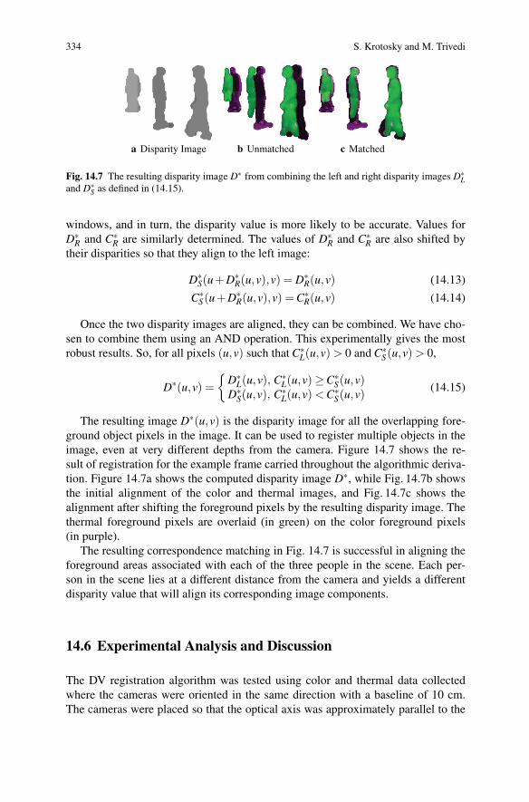
Fig. 14.7 The resulting disparity image D∗ from combining the left and right disparity images D∗L
and D∗S as defined in (14.15).
windows, and in turn, the disparity value is more likely to be accurate. Values forD∗
R and C∗R are similarly determined. The values of D∗
R and C∗R are also shifted by
their disparities so that they align to the left image:
D∗S(u+D∗
R(u,v),v) = D∗R(u,v) (14.13)
C∗S(u+D∗
R(u,v),v) = C∗R(u,v) (14.14)
Once the two disparity images are aligned, they can be combined. We have cho-sen to combine them using an AND operation. This experimentally gives the mostrobust results. So, for all pixels (u,v) such that C∗
L(u,v) > 0 and C∗S(u,v) > 0,
D∗(u,v) ={
D∗L(u,v), C∗
L(u,v)≥C∗S(u,v)
D∗S(u,v), C∗
L(u,v) < C∗S(u,v) (14.15)
The resulting image D∗(u,v) is the disparity image for all the overlapping fore-ground object pixels in the image. It can be used to register multiple objects in theimage, even at very different depths from the camera. Figure 14.7 shows the re-sult of registration for the example frame carried throughout the algorithmic deriva-tion. Figure 14.7a shows the computed disparity image D∗, while Fig. 14.7b showsthe initial alignment of the color and thermal images, and Fig. 14.7c shows thealignment after shifting the foreground pixels by the resulting disparity image. Thethermal foreground pixels are overlaid (in green) on the color foreground pixels(in purple).
The resulting correspondence matching in Fig. 14.7 is successful in aligning theforeground areas associated with each of the three people in the scene. Each per-son in the scene lies at a different distance from the camera and yields a differentdisparity value that will align its corresponding image components.
14.6 Experimental Analysis and Discussion
The DV registration algorithm was tested using color and thermal data collectedwhere the cameras were oriented in the same direction with a baseline of 10 cm.The cameras were placed so that the optical axis was approximately parallel to the
14 Registration Multimodal Imagery 335
a Unregistered b Registration
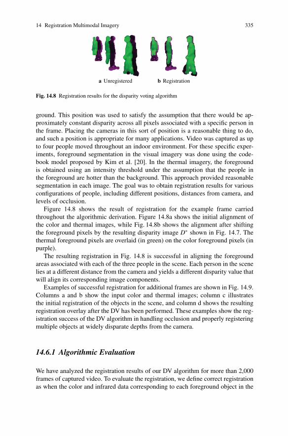
Fig. 14.8 Registration results for the disparity voting algorithm
ground. This position was used to satisfy the assumption that there would be ap-proximately constant disparity across all pixels associated with a specific person inthe frame. Placing the cameras in this sort of position is a reasonable thing to do,and such a position is appropriate for many applications. Video was captured as upto four people moved throughout an indoor environment. For these specific exper-iments, foreground segmentation in the visual imagery was done using the code-book model proposed by Kim et al. [20]. In the thermal imagery, the foregroundis obtained using an intensity threshold under the assumption that the people inthe foreground are hotter than the background. This approach provided reasonablesegmentation in each image. The goal was to obtain registration results for variousconfigurations of people, including different positions, distances from camera, andlevels of occlusion.
Figure 14.8 shows the result of registration for the example frame carriedthroughout the algorithmic derivation. Figure 14.8a shows the initial alignment ofthe color and thermal images, while Fig. 14.8b shows the alignment after shiftingthe foreground pixels by the resulting disparity image D∗ shown in Fig. 14.7. Thethermal foreground pixels are overlaid (in green) on the color foreground pixels (inpurple).
The resulting registration in Fig. 14.8 is successful in aligning the foregroundareas associated with each of the three people in the scene. Each person in the scenelies at a different distance from the camera and yields a different disparity value thatwill align its corresponding image components.
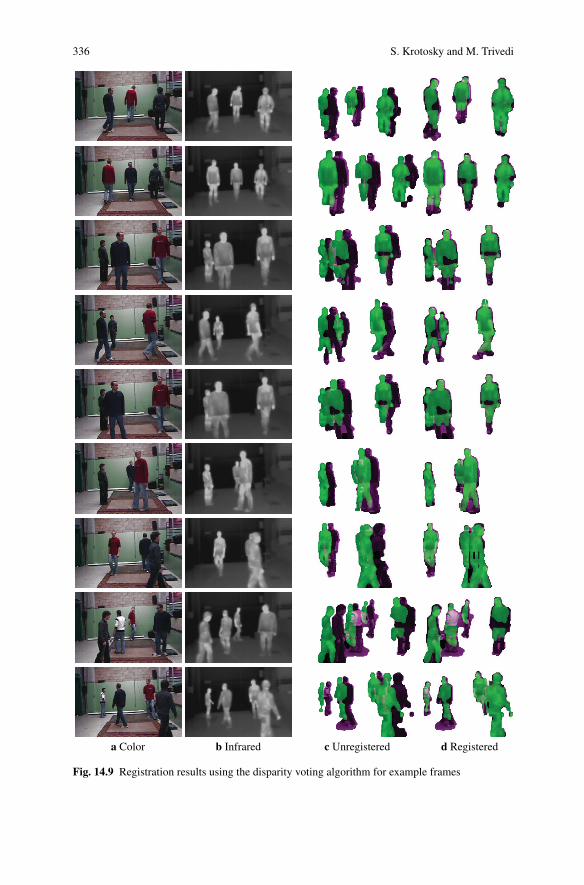
Examples of successful registration for additional frames are shown in Fig. 14.9.Columns a and b show the input color and thermal images; column c illustratesthe initial registration of the objects in the scene, and column d shows the resultingregistration overlay after the DV has been performed. These examples show the reg-istration success of the DV algorithm in handling occlusion and properly registeringmultiple objects at widely disparate depths from the camera.
14.6.1 Algorithmic Evaluation
We have analyzed the registration results of our DV algorithm for more than 2,000frames of captured video. To evaluate the registration, we define correct registrationas when the color and infrared data corresponding to each foreground object in the
336 S. Krotosky and M. Trivedi
a Color b Infrared c Unregistered d Registered
Fig. 14.9 Registration results using the disparity voting algorithm for example frames
14 Registration Multimodal Imagery 337
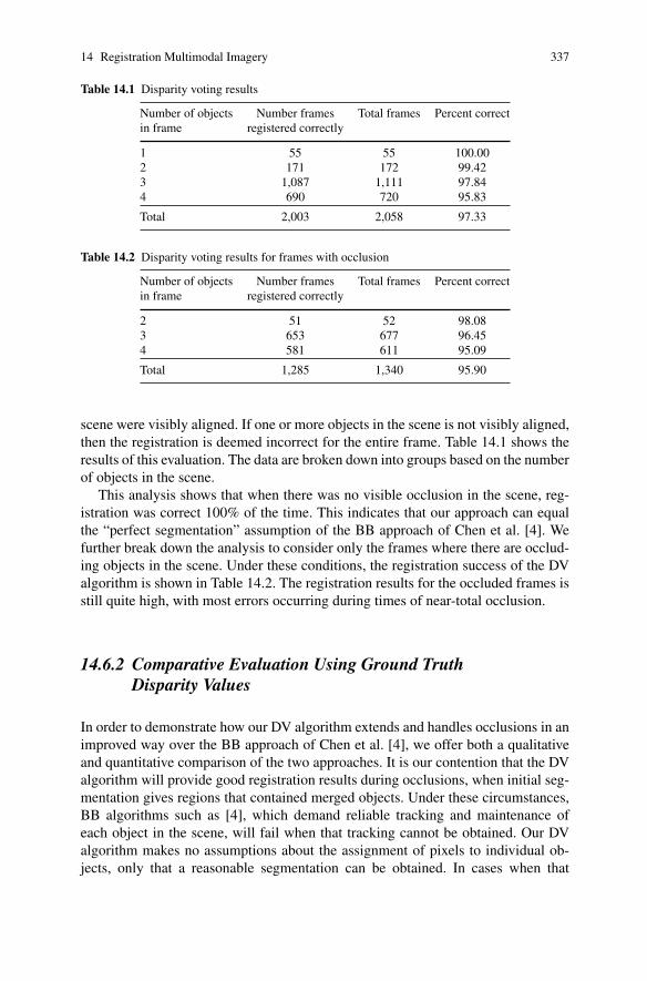
Table 14.1 Disparity voting results
Number of objects Number frames Total frames Percent correctin frame registered correctly
1 55 55 100.002 171 172 99.423 1,087 1,111 97.844 690 720 95.83
Total 2,003 2,058 97.33
Table 14.2 Disparity voting results for frames with occlusion
Number of objects Number frames Total frames Percent correctin frame registered correctly
2 51 52 98.083 653 677 96.454 581 611 95.09
Total 1,285 1,340 95.90
scene were visibly aligned. If one or more objects in the scene is not visibly aligned,then the registration is deemed incorrect for the entire frame. Table 14.1 shows theresults of this evaluation. The data are broken down into groups based on the numberof objects in the scene.
This analysis shows that when there was no visible occlusion in the scene, reg-istration was correct 100% of the time. This indicates that our approach can equalthe “perfect segmentation” assumption of the BB approach of Chen et al. [4]. Wefurther break down the analysis to consider only the frames where there are occlud-ing objects in the scene. Under these conditions, the registration success of the DValgorithm is shown in Table 14.2. The registration results for the occluded frames isstill quite high, with most errors occurring during times of near-total occlusion.
14.6.2 Comparative Evaluation Using Ground TruthDisparity Values
In order to demonstrate how our DV algorithm extends and handles occlusions in animproved way over the BB approach of Chen et al. [4], we offer both a qualitativeand quantitative comparison of the two approaches. It is our contention that the DValgorithm will provide good registration results during occlusions, when initial seg-mentation gives regions that contained merged objects. Under these circumstances,BB algorithms such as [4], which demand reliable tracking and maintenance ofeach object in the scene, will fail when that tracking cannot be obtained. Our DValgorithm makes no assumptions about the assignment of pixels to individual ob-jects, only that a reasonable segmentation can be obtained. In cases when that
338 S. Krotosky and M. Trivedi
segmentation does not include occlusion, we demonstrate successful registrationon par with BB methods. In cases of occlusion, we demonstrate that the DV reg-istration performance outperforms BB approaches and can successfully register allobjects in the scene.
To demonstrate the utility of the DV algorithm for handling registration with oc-cluding objects, we compare the BB and DV techniques when we have ground truthbackground segmentation. We generate the ground truth by manually segmentingthe regions that correspond to foreground for each image. We then determine theground truth disparity by individually matching each manually segmented object inthe scene. This ground truth disparity image allows us to directly and quantitativelycompare the registration success of the DV algorithm and the BB approach. Thedesire is to show that even during perfect background segmentation, BB approachescan only perform successful registration if there is no occlusion or if there is per-fect tracking to assign object ownership to the pixels in the segmented foreground.By comparing the registration results to the ground truth disparities, we are able toquantify the success of each algorithm and show that the DV algorithm outperformsthe BB approach for occluding object regions.
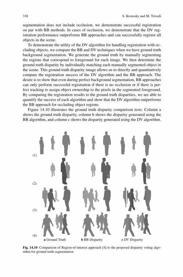
Figure 14.10 illustrates the ground truth disparity comparison tests. Column ashows the ground truth disparity, column b shows the disparity generated using theBB algorithm, and column c shows the disparity generated using the DV algorithm.
(1)
(2)
(3)
(4)a Ground Truth b BB Disparity c DV Disparity
Fig. 14.10 Comparison of Region-of-interest approach [4] to the proposed disparity voting algo-rithm for ground truth segmentation
14 Registration Multimodal Imagery 339
00.20.40.60.8
11.21.41.61.8
2
50 100 150 200 250
a Fig. 14.10.150 100 150 200 250
0123456789
10
b Fig. 14.10.2
0123456789
10
50 100 150 200 250
c Fig. 14.10.350 100 150 200 2500
1
2
3
4
5
6
d Fig. 14.10.4
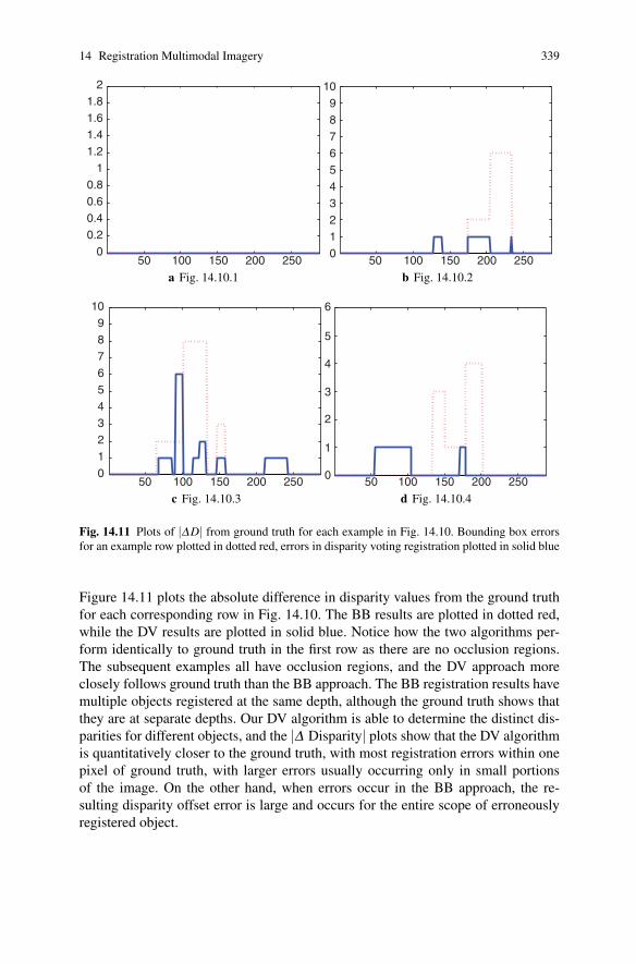
Fig. 14.11 Plots of |ΔD| from ground truth for each example in Fig. 14.10. Bounding box errorsfor an example row plotted in dotted red, errors in disparity voting registration plotted in solid blue
Figure 14.11 plots the absolute difference in disparity values from the ground truthfor each corresponding row in Fig. 14.10. The BB results are plotted in dotted red,while the DV results are plotted in solid blue. Notice how the two algorithms per-form identically to ground truth in the first row as there are no occlusion regions.The subsequent examples all have occlusion regions, and the DV approach moreclosely follows ground truth than the BB approach. The BB registration results havemultiple objects registered at the same depth, although the ground truth shows thatthey are at separate depths. Our DV algorithm is able to determine the distinct dis-parities for different objects, and the |Δ Disparity| plots show that the DV algorithmis quantitatively closer to the ground truth, with most registration errors within onepixel of ground truth, with larger errors usually occurring only in small portionsof the image. On the other hand, when errors occur in the BB approach, the re-sulting disparity offset error is large and occurs for the entire scope of erroneouslyregistered object.
340 S. Krotosky and M. Trivedi
14.6.3 Comparative Assessment of Registration Algorithmswith Nonideal Segmentation
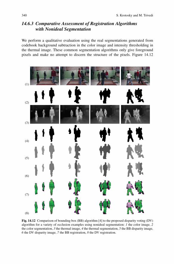
We perform a qualitative evaluation using the real segmentations generated fromcodebook background subtraction in the color image and intensity thresholding inthe thermal image. These common segmentation algorithms only give foregroundpixels and make no attempt to discern the structure of the pixels. Figure 14.12
(1)
(2)
(3)
(4)
(5)
(6)
(7)
(8)
Fig. 14.12 Comparison of bounding box (BB) algorithm [4] to the proposed disparity voting (DV)algorithm for a variety of occlusion examples using nonideal segmentation: 1 the color image, 2the color segmentation, 3 the thermal image, 4 the thermal segmentation, 5 the BB disparity image,6 the DV disparity image, 7 the BB registration, 8 the DV registration.
14 Registration Multimodal Imagery 341
a BB Registration b DV Registration
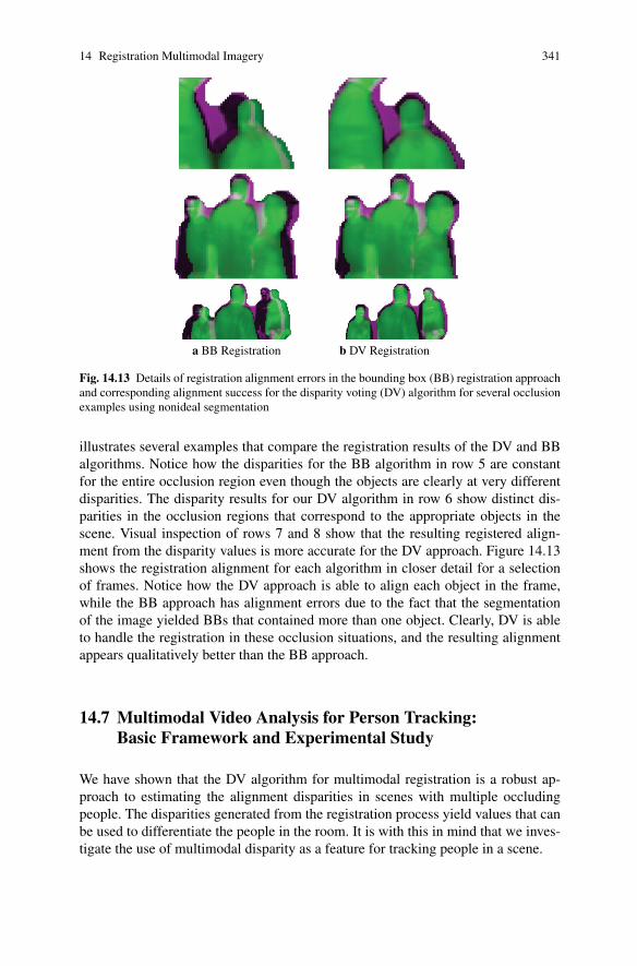
Fig. 14.13 Details of registration alignment errors in the bounding box (BB) registration approachand corresponding alignment success for the disparity voting (DV) algorithm for several occlusionexamples using nonideal segmentation
illustrates several examples that compare the registration results of the DV and BBalgorithms. Notice how the disparities for the BB algorithm in row 5 are constantfor the entire occlusion region even though the objects are clearly at very differentdisparities. The disparity results for our DV algorithm in row 6 show distinct dis-parities in the occlusion regions that correspond to the appropriate objects in thescene. Visual inspection of rows 7 and 8 show that the resulting registered align-ment from the disparity values is more accurate for the DV approach. Figure 14.13shows the registration alignment for each algorithm in closer detail for a selectionof frames. Notice how the DV approach is able to align each object in the frame,while the BB approach has alignment errors due to the fact that the segmentationof the image yielded BBs that contained more than one object. Clearly, DV is ableto handle the registration in these occlusion situations, and the resulting alignmentappears qualitatively better than the BB approach.
14.7 Multimodal Video Analysis for Person Tracking:Basic Framework and Experimental Study
We have shown that the DV algorithm for multimodal registration is a robust ap-proach to estimating the alignment disparities in scenes with multiple occludingpeople. The disparities generated from the registration process yield values that canbe used to differentiate the people in the room. It is with this in mind that we inves-tigate the use of multimodal disparity as a feature for tracking people in a scene.
342 S. Krotosky and M. Trivedi
a Frame 0 b Frame 20 c Frame 40
d Frame 60 e Frame 80 f Frame 100
g Frame 120 h Frame 140
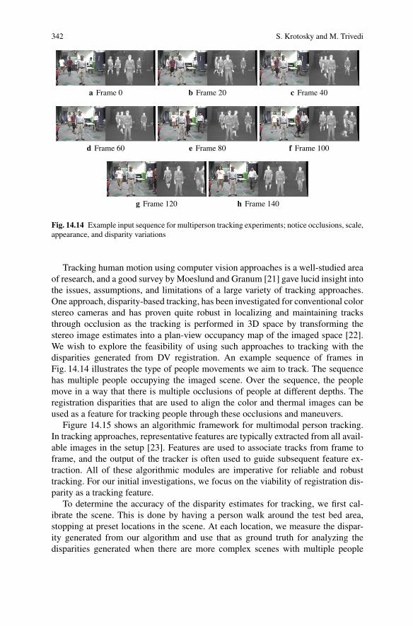
Fig. 14.14 Example input sequence for multiperson tracking experiments; notice occlusions, scale,appearance, and disparity variations
Tracking human motion using computer vision approaches is a well-studied areaof research, and a good survey by Moeslund and Granum [21] gave lucid insight intothe issues, assumptions, and limitations of a large variety of tracking approaches.One approach, disparity-based tracking, has been investigated for conventional colorstereo cameras and has proven quite robust in localizing and maintaining tracksthrough occlusion as the tracking is performed in 3D space by transforming thestereo image estimates into a plan-view occupancy map of the imaged space [22].We wish to explore the feasibility of using such approaches to tracking with thedisparities generated from DV registration. An example sequence of frames inFig. 14.14 illustrates the type of people movements we aim to track. The sequencehas multiple people occupying the imaged scene. Over the sequence, the peoplemove in a way that there is multiple occlusions of people at different depths. Theregistration disparities that are used to align the color and thermal images can beused as a feature for tracking people through these occlusions and maneuvers.
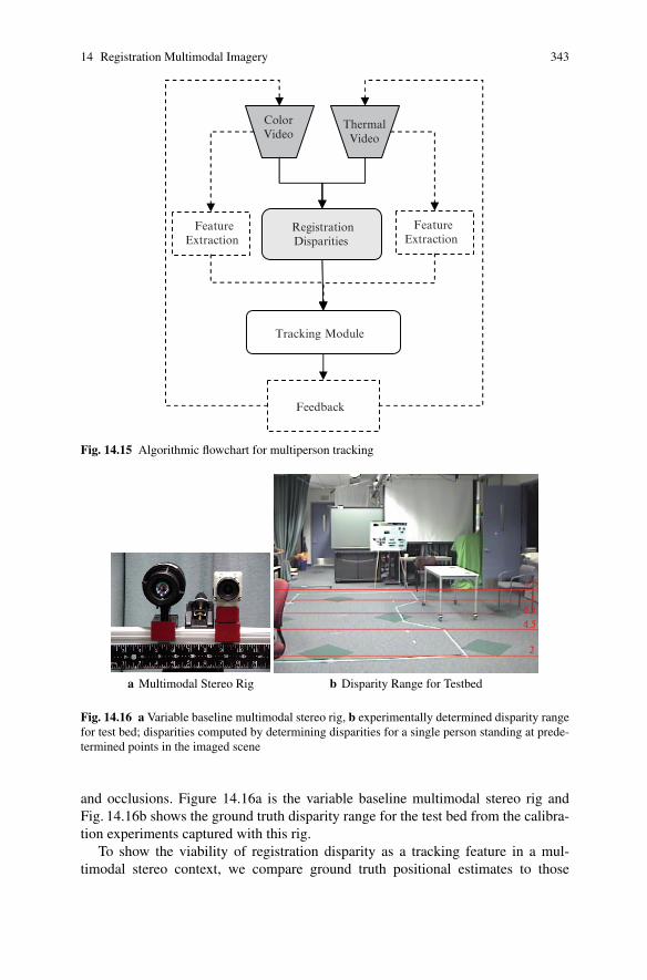
Figure 14.15 shows an algorithmic framework for multimodal person tracking.In tracking approaches, representative features are typically extracted from all avail-able images in the setup [23]. Features are used to associate tracks from frame toframe, and the output of the tracker is often used to guide subsequent feature ex-traction. All of these algorithmic modules are imperative for reliable and robusttracking. For our initial investigations, we focus on the viability of registration dis-parity as a tracking feature.
To determine the accuracy of the disparity estimates for tracking, we first cal-ibrate the scene. This is done by having a person walk around the test bed area,stopping at preset locations in the scene. At each location, we measure the dispar-ity generated from our algorithm and use that as ground truth for analyzing thedisparities generated when there are more complex scenes with multiple people
14 Registration Multimodal Imagery 343
ColorVideo
ThermalVideo
RegistrationDisparities
FeatureExtraction
FeatureExtraction
Tracking Module
Feedback
Fig. 14.15 Algorithmic flowchart for multiperson tracking
a Multimodal Stereo Rig b Disparity Range for Testbed
Fig. 14.16 a Variable baseline multimodal stereo rig, b experimentally determined disparity rangefor test bed; disparities computed by determining disparities for a single person standing at prede-termined points in the imaged scene
and occlusions. Figure 14.16a is the variable baseline multimodal stereo rig andFig. 14.16b shows the ground truth disparity range for the test bed from the calibra-tion experiments captured with this rig.
To show the viability of registration disparity as a tracking feature in a mul-timodal stereo context, we compare ground truth positional estimates to those
344 S. Krotosky and M. Trivedi
0 5 10 15 20 25 30
lateral position (pixels x 10−1)
disp
arity
(pi
xels
)
0
1
2
3
4
5
6
7
8
a Track patterns and ground truth for four-person tracking experiment
010
2030
40
02
46
8
lateral position (pixels x 10−1)disparity (pixels)
fram
e
0
20
40
60
80
100
120
140
b Time-varying track patterns and ground truth for four person trackingexperiment
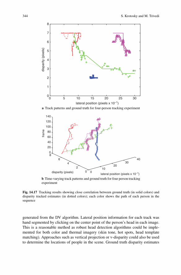
Fig. 14.17 Tracking results showing close correlation between ground truth (in solid colors) anddisparity tracked estimates (in dotted colors); each color shows the path of each person in thesequence
generated from the DV algorithm. Lateral position information for each track washand segmented by clicking on the center point of the person’s head in each image.This is a reasonable method as robust head detection algorithms could be imple-mented for both color and thermal imagery (skin tone, hot spots, head templatematching). Approaches such as vertical projection or v-disparity could also be usedto determine the locations of people in the scene. Ground truth disparity estimates
14 Registration Multimodal Imagery 345
were generated by visually determining the disparity based on the person’s positionrelative to the ground truth disparity range map as shown in Fig. 14.16. Experimen-tal disparities were generated using the DV algorithm with the disparity of eachperson determined from disparity values in the head region. A moving average of150 ms was used to smooth instantaneous disparity estimates.
Figure 14.17 shows the track patterns and ground truth for the example sequencein Fig. 14.14. The ground truth is plotted in solid colors for each person in the se-quence, while the disparity estimates from the DV algorithm are shown in corre-sponding colored symbols with dotted lines connecting the estimates. Figure 14.17ais a representation of the tracks, illustrating a “plan-view”-like representation of themovements and disparity changes of the people in the test bed. Figure 14.17b showsa time-varying version of the same data, with the frame number plotted in the thirddimension.
The plots in Fig. 14.17 show that the disparities generated from the DV registra-tion reasonably follow the ground truth tracks. As the green tracked person movesbehind and becomes occluded by the blue tracked person, we see that the disparitiesgenerated when the person reemerges from the occlusion are in line with the groundtruth disparities and can be used to reassociate the track after the occlusion.
Errors from ground truth are particularly apparent when people are further fromthe camera. This is because of the nonlinearity of the disparity distribution. Thereare more distinct disparities nearer to the camera. As you move deeper in the scenein Fig. 14.16, the change in disparity for the same change in distance is much less.At these distances, errors of even one disparity shift are very pronounced. Con-ventional stereo algorithms typically used approaches that give subpixel accuracy,but the current implementation of our DV algorithm only gives pixel-level dispar-ity shifts. While this may be acceptable for registration alignment, refinement stepsare necessary to make disparity a more robust tracking feature. Approaches thatuse multiple primitives [24], such as edges, shapes, silhouettes, and the like, couldbe used to augment the accuracy of the DV algorithm. In addition, using multipletracking features could provide additional measurements that can be used to boostthe association accuracy.
14.8 Summary and Concluding Remarks
In this chapter, we have introduced and analyzed a method for registering multi-modal images with occluding objects in the scene. By using a DV approach, thealgorithm has given successful and reliable registration without relying on anyassumptions about the tracked ownership of pixels to object regions in the scene.An analysis of over 2,000 frames yielded a registration success rate of over 97%,with a 96% success rate when considering only occlusion examples. In addition,ground truth and segmentation comparisons illustrate how the DV algorithm im-proves the registration accuracy and robustness of previous BB techniques in bothquantitative and qualitative evaluations. DV gives the ability to determine accurate
346 S. Krotosky and M. Trivedi
registration disparities for occluded objects that can be used as a feature of objectsin the scene for further detection, tracking, and analysis.
Multimodal imagery applications for human analysis span a variety of appli-cation domains, including medical [25], in-vehicle safety systems [26], and long-range surveillance [2]. Typically, these types of systems do not operate on data thathave multiple objects and multiple depths that are significant relative to their dis-tance from the camera. It is in this realm, including short-range surveillance [18]and pedestrian detection applications [27], that we believe DV registration tech-niques will prove useful.
Acknowledgment We would like to thank our research sponsors, the U.S. Department of DefenseTechnical Support Working Group and the U.C. Discovery Grant. In addition, we owe gratitudeto the members of the Computer Vision and Robotics Research Laboratory, particularly Dr. JoelMcCall and Mr. Shinko Cheng.
We would also like to express our thanks to the reviewers for their comments and assistance,which helped us improve our research.
Chapter’s References
1. Bertozzi, M., Broggi, A., Felias, M., Vezzoni, G., Rose, M.D. (2006) Low-level pedestriandetection by means of visible and far infra-red tetra-vision. In: IEEE Conference on IntelligentVehicles
2. Davis, J., Sharma, V. (2005) Fusion-based background-subtraction using contour saliency. In:IEEE CVPR Workshop on Object Tracking and Classification beyond the Visible Spectrum
3. Egnal, G. (2000) Mutual information as a stereo correspondence measure. Technical ReportMS-CIS-00-20, University of Pennsylvania
4. Chen, H., Varshney, P., Slamani, M. (2003) On registration of regions of interest (ROI) invideo sequences. In: IEEE International Conference on Advanced Video and Signal BasedSurveillance (AVSS’03), pp. 313
5. Conaire, C.O., Cooke, E., O’Connor, N., Murphy, N., Smeaton, A. (2005) Background mod-eling in infrared and visible spectrum video for people tracking. In: IEEE CVPR Workshopon Object Tracking and Classification beyond the Visible Spectrum
6. Han, J., Bhanu, B. (2003) Detecting moving humans using color and infrared video. In: IEEEInternational Conference on Multisensor Fusion and Integration for Intelligent Systems
7. Itoh, M., Ozeki, M., Nakamura, Y., Ohta, Y. (2003) Simple and robust tracking of hands andobjects for video-based multimedia production. In: IEEE Conference on Multisensor Fusionand Integration for Intelligent Systems
8. Irani, M., Anandan, P. (1998) Robust multi-sensor image alignment. In: Sixth InternationalConference on Computer Vision, 1998
9. Coiras, E., Santamaria, J., Miravet, C. (2000) Segment-based registration technique for visual-infrared images. Optical Engineering 39(1), 282–289
10. Chen, H., Lee, S., Rao, R., Slamani, M., Varshney, P. (2005) Imaging for concealed weapondetection. Signal Processing Magazine, IEEE Vol. 22, Issue 2, March 2005, pp. 52–61
11. Kim, J., Kolmogorov, V., Zabih, R. (2003) Visual correspondence using energy minimizationand mutual information. In: Ninth IEEE International Conference on Computer Vision
12. H. Hirschmuller (2005) Accurate and efficient stereo processing by semi-global matching andmutual information. In: Computer Vision and Pattern Recognition
13. Scharstein, D., Szeliski, R. (2005) Middlebury College stereo vision research page.http://bj.middlebury.edu/∼schar/stereo/web/results.php
14 Registration Multimodal Imagery 347
14. Marapane, S., Trivedi, M. (1989) Region-based stereo analysis for robotic applications. IEEETransactions on Systems, Man, and Cybernetics, Special Issue on Computer Vision 19(6),1447–1464
15. Cohen, L., Vinet, L., Sander, P., Gagalowicz, A. (1989) Hierarchical region based stereomatching. In: Computer Vision and Pattern Recognition
16. Wei, Y., Quan, L. (2004) Region-based progressive stereo matching. In: Computer Vision andPattern Recognition
17. Bleyer, M., Gelautz, M. (2005) Graph-based surface reconstruction from stereo pairs usingimage segmentation. Proc. SPIE 5665, 288–299
18. Krotosky, S.J., Trivedi, M.M. (2006) Registration of multimodal stereo images using disparityvoting from correspondence windows. In: IEEE Conference on Advanced Video and Signalbased Surveillance (AVSS’06)
19. Thevenaz, P., Unser, M. (2000) Optimization of mutual information for multiresolution imageregistration. IEEE Transactions on Image Processing 9(12), 2083–2089
20. Kim, K., Chalidabhongse, T., Harwood, D., Davis, L. (2005) Real-time foreground-background segmentation using codebook model. Real-Time Imaging 11(3), 163–256
21. Moesland, T.B., Granum, E. (2001) A survey of computer vision-based human motion capture.Computer Vision and Image Understanding 81(3), 231–268
22. Harville, M., Li, D. (2004) Fast, integrated person tracking and activity recognition with plan-view templates from a single stereo camera. In: IEEE Conference on Computer Vision andPattern Recognition
23. Huang, K., Trivedi, M.M. (2003) Video arrays for real-time tracking of person, head, and facein an intelligent room. Machine Vision and Applications 14(2), 103–111
24. Marapane, S., Trivedi, M.M. (1994) Multi-primitive hierarchical (MPH) stereo analysis. IEEETransactions on Pattern Analysis and Machine Intelligence 16(3), 227–240
25. Thevenaz, P., Bierlaire, M., Unser, M.: Halton sampling for image registration based on mutualinformation. Sampling Theory in Signal and Image Processing, May, 2008
26. Trivedi, M.M., Cheng, S.Y., Childers, E.M.C., Krotosky, S.J. (2004) Occupant posture anal-ysis with stereo and thermal infrared video: Algorithms and experimental evaluation. IEEETransactions on Vehicle Technology 53(6), 1968–1712
27. Krotosky, S.J., Trivedi, M.M. (2006) Multimodal stereo image registration for predestriandetection. In: IEEE Conference on Intelligent Transportation Systems


![Monitoria multimodal cerebral multimodal monitoring[2]](https://img.pdfslide.us/doc/110x75/552957004a79599a158b46fd/monitoria-multimodal-cerebral-multimodal-monitoring2.jpg)