Embed Size (px)
Citation preview

1
CHAPTER 14 EXTERIOR WALLS
User notes:
About this chapter: Chapter 14 addresses requirements for exterior walls of buildings. Minimum standards for wall covering materials, such as material performance and fire resistance, installation of wall coverings and the ability of the wall to provide weather protection are provided. This chapter also contains limitations on the areas and heights of combustible wall coverings based on fire separation distances, radiant heat exposure and surface burning characteristics.
Code development reminder: Code change proposals to sections preceded by the designation [BS] will be considered by the IBC—Structural Code Development Committee during the 2022 (Group B) Code Development Cycle.
SECTION 1401
GENERAL 1401.1 Scope. The provisions of this chapter shall establish the minimum requirements for exterior walls; exterior wall coverings; exterior wall openings; exterior windows and doors; and architectural trim.
SECTION 1402
PERFORMANCE REQUIREMENTS 1402.1 General. The provisions of this section shall apply to exterior walls, wall coverings and components thereof. 1402.2 Weather protection. Exterior walls shall provide the building with a weather-resistant exterior wall envelope. The exterior wall envelope shall include flashing, as described in Section 1404.4. The exterior wall envelope shall be designed and constructed in such a manner as to prevent the accumulation of water within the wall assembly by providing a water-resistive barrier behind the exterior veneer, as described in Section 1403.2, and a means for draining water that enters the assembly to the exterior. Protection against condensation in the exterior wall assembly shall be provided in accordance with Section 1404.3.
Exceptions:
1. A weather-resistant exterior wall envelope shall not be required over concrete or masonry
walls designed in accordance with Chapters 19 and 21, respectively.
2. Compliance with the requirements for a means of drainage, and the requirements of
Sections 1403.2 and 1404.4, shall not be required for an exterior wall envelope that has been demonstrated through testing to resist wind-driven rain, including joints, penetrations and intersections with dissimilar materials, in accordance with ASTM E331 under the following conditions:
The exterior wall envelope design shall be considered to resist wind-driven rain where the
results of testing indicate that water did not penetrate control joints in the exterior wall envelope, joints at the perimeter of openings or intersections of terminations with dissimilar materials.

2
2.1. Exterior wall envelope test assemblies shall include not fewer than one opening, one
control joint, one wall/eave interface and one wall sill. Tested openings and penetrations shall be representative of the intended end-use configuration.
2.2. Exterior wall envelope test assemblies shall be not less than 4 feet by 8 feet (1219
mm by 2438 mm) in size.
2.3. Exterior wall envelope assemblies shall be tested at a minimum differential pressure
of 6.24 pounds per square foot (0.297 kN/m2).
2.4. Exterior wall envelope assemblies shall be subjected to a minimum test exposure
duration of 2 hours.
3. Exterior insulation and finish systems (EIFS) complying with Section 1407.4.1.
[BS] 1402.3 Structural. Exterior walls, and the associated openings, shall be designed and constructed to resist safely the superimposed loads required by Chapter 16. 1402.4 Fire resistance. Exterior walls shall be fire-resistance rated as required by other sections of this code with opening protection as required by Chapter 7. 1402.5 Water-resistive barriers. Exterior walls on buildings of Type I, II, III or IV construction that are greater than 40 feet (12 192 mm) in height above grade plane and contain a combustible water-resistive barrier shall be tested in accordance with and comply with the acceptance criteria of NFPA 285.Combustibility shall be determined in accordance with Section 703.3. For the purposes of this section, fenestration products, flashing of fenestration products and water-resistive-barrier flashing and accessories at other locations, including through wall flashings, shall not be considered part of the water-resistive barrier.
Exceptions:
1. Walls in which the water-resistive barrier is the only combustible component and the exterior wall has
a wall covering of brick, concrete, stone, terra cotta, stucco or steel with minimum thicknesses in accordance with Table 1404.2.
2. Walls in which the water-resistive barrier is the only combustible component and the water-resistive barrier complies with the following:
2.1. A peak heat release rate of less than 150 kW/m2, a total heat release of less than 20
MJ/m2 and an effective heat of combustion of less than 18 MJ/kg when tested on specimens at the thickness intended for use, in accordance with ASTM E1354, in the horizontal orientation and at an incident radiant heat flux of 50 kW/m2.
2.2. A flame spread index of 25 or less and a smoke-developed index of 450 or less as
determined in accordance with ASTM E84 or UL 723, with test specimen preparation and mounting in accordance with ASTM E2404.
[BS] 1402.6 Flood resistance. For buildings in flood hazard areas as established in Section 1612.3, exterior walls extending below the elevation required by Section 1612 shall be constructed with flood-damage-resistant materials.

3
[BS] 1402.7 Flood resistance for coastal high-hazard areas and coastal A zones. For buildings in coastal high-hazard areas and coastal A zones as established in Section 1612.3, electrical, mechanical and plumbing system components shall not be mounted on or penetrate through exterior walls that are designed to break away under flood loads.
SECTION 1403
MATERIALS 1403.1 General. Materials used for the construction of exterior walls shall comply with the provisions of this section. Materials not prescribed herein shall be permitted, provided that any such alternative has been approved. 1403.2 Water-resistive barrier. Not fewer than one layer of water-resistive barrier material shall be attached to the studs or sheathing, with flashing as described in Section 1404.4, in such a manner as to provide a continuous water-resistive barrier behind the exterior wall veneer. Water-resistive barriers shall comply with one of the following:
1. No. 15 felt complying with ASTM D226, Type 1.
2. ASTM E2556, Type I or II.
3. ASTM E331 in accordance with Section 1402.2.
4. Other approved materials installed in accordance with the manufacturer’s installation instructions.
[BS] 1403.3 Wood. Exterior walls of wood construction shall be designed and constructed in accordance with Chapter 23.
[BS] 1403.3.1 Basic hardboard. Basic hardboard shall conform to the requirements of ANSI A135.4.
[BS] 1403.3.2 Hardboard siding. Hardboard siding shall conform to the requirements of ANSI A135.6 and, where used structurally, shall be so identified by the label of an approved agency.
[BS] 1403.4 Masonry. Exterior walls of masonry construction shall be designed and constructed in accordance with this section and Chapter 21. Masonry units, mortar and metal accessories used in anchored and adhered veneer shall meet the physical requirements of Chapter 21. The backing of anchored and adhered veneer shall be of concrete, masonry, steel framing or wood framing. Continuous insulation meeting the applicable requirements of this code shall be permitted between the backing and the masonry veneer.
[BS] 1403.5 Metal. Exterior walls constructed of cold-formed or structural steel shall be designed in accordance with Chapter 22. Exterior walls constructed of aluminum shall be designed in accordance with Chapter 20.
[BS] 1403.5.1 Aluminum siding. Aluminum siding shall conform to the requirements of AAMA 1402.

4
[BS] 1403.5.2 Cold-rolled copper. Copper shall conform to the requirements of ASTM B370.
[BS] 1403.5.3 Lead-coated copper. Lead-coated copper shall conform to the requirements of ASTM B101.
[BS] 1403.6 Concrete. Exterior walls of concrete construction shall be designed and constructed in accordance with Chapter 19.
[BS] 1403.7 Glass-unit masonry Exterior walls of glass-unit masonry shall be designed and constructed in accordance with Chapter 21. 1403.8 Plastics. Plastic panel, apron or spandrel walls as defined in this code shall not be limited in thickness, provided that such plastics and their assemblies conform to the requirements of Chapter 26 and are constructed of approved weather-resistant materials of adequate strength to resist the wind loads for cladding specified in Chapter 16. 1403.9 Vinyl siding. Vinyl siding shall be certified and labeled as conforming to the requirements of ASTM D3679 by an approved quality control agency. 1403.10 Fiber-cement siding. Fiber-cement siding shall conform to the requirements of ASTM C1186, Type A (or ISO 8336, Category A), and shall be so identified on labeling listing an approved quality control agency. 1403.11 Exterior insulation and finish systems. Exterior insulation and finish systems (EIFS) and exterior insulation and finish systems (EIFS) with drainage shall comply with Section 1407.
1403.12 Polypropylene siding. Polypropylene siding shall be certified and labeled as conforming to the requirements of ASTM D7254 and those of Section 1403.12.1 or 1403.12.2 by an approved quality control agency. Polypropylene siding shall be installed in accordance with the requirements of Section 1404.18 and in accordance with the manufacturer’s instructions. Polypropylene siding shall be secured to the building so as to provide weather protection for the exterior walls of the building.
1403.12.1 Flame spread index. The certification of the flame spread index shall be accompanied by a test report stating that all portions of the test specimen ahead of the flame front remained in position during the test in accordance with ASTM E84 or UL 723.
1403.12.2 Fire separation distance. The fire separation distance between a building with polypropylene siding and the adjacent building shall be not less than 10 feet (3048 mm).
1403.13 Foam plastic insulation. Foam plastic insulation used in exterior wall covering assemblies shall comply with Chapter 26.
1403.14 Attachments through insulation. Exterior wall coverings attached to the building structure through foam plastic insulating sheathing shall comply with the attachment requirements of Section 2603.11, 2603.12, or 2603.13.

5
SECTION 1404 INSTALLATION OF WALL COVERINGS
1404.1 General. Exterior wall coverings shall be designed and constructed in accordance with the applicable provisions of this section. 1404.2 Weather protection. Exterior walls shall provide weather protection for the building. The materials of the minimum nominal thickness specified in Table 1404.2 shall be acceptable as approved weather coverings.
TABLE 1404.2
MINIMUM THICKNESS OF WEATHER COVERINGS
COVERING TYPE MINIMUM THICKNESS
(inches) Adhered masonry veneer 0.25
Aluminum siding 0.019
Anchored masonry veneer
Stone (natural) 2.0
Architectural cast stone 2.5
Other 2.0
Asbestos-cement boards 0.125
Asbestos shingles 0.156
Cold-rolled copperd 0.0216 nominal
Copper shinglesd 0.0162 nominal
Exterior plywood (with sheathing) 0.313
Exterior plywood (without sheathing) See Section 2304.6
Fiber cement lap siding 0.25c
Fiber cement panel siding 0.25c
Fiberboard siding 0.5
Glass-fiber reinforced concrete panels 0.375
Hardboard sidingc 0.25
High-yield copperd 0.0162 nominal
Lead-coated copperd 0.0216 nominal
Lead-coated high-yield copper 0.0162 nominal
Marble slabs 1
Particleboard (with sheathing) See Section 2304.6
Particleboard (without sheathing) See Section 2304.6
Porcelain tile 0.125 nominal
Steel (approved corrosion resistant) 0.0149
Structural glass 0.344
Stucco or exterior cement plaster
Three-coat work over:
Metal plaster base 0.875b
Unit masonry 0.625b
Cast-in-place or precast concrete 0.625b
Two-coat work over:
Unit masonry 0.5b
Cast-in-place or precast concrete 0.375b
Terra cotta (anchored) 1
Terra cotta (adhered) 0.25
Vinyl siding 0.035
Wood shingles 0.375
Wood siding (without sheathing)a 0.5

6
For SI: 1 inch = 25.4 mm, 1 ounce = 28.35 g, 1 square foot = 0.093 m2
. a. Wood siding of thicknesses less than 0.5 inch shall be placed over sheathing that conforms to Section 2304.6. b. Exclusive of texture. c. As measured at the bottom of decorative grooves. d. 16 ounces per square foot for cold-rolled copper and lead-coated copper, 12 ounces per square foot for copper shingles,
high-yield copper and lead-coated high-yield copper.
1404.3 Vapor retarders. Vapor retarder materials shall be classified in accordance with Table 1404.3(1). A vapor retarder shall be provided on the interior side of frame walls in accordance with Tables 1404.3(2) and 1404.3(3), or an approved design using accepted engineering practice for hygrothermal analysis. The appropriate climate zone shall be selected in accordance with Chapter 3 of the International Energy Conservation Code.
TABLE 1404.3(1) VAPOR RETARDER MATERIALS AND CLASSES
VAPOR
RETARDER CLASS
ACCEPTABLE MATERIALS
I Sheet polyethylene, nonperforated aluminum foil, or other approved materials with a perm rating of less than or equal to 0.1
II
Kraft-faced fiberglass batts or vapor retarder paint or other approved materials, applied in accordance with the manufacturer’s instructions for a perm rating greater than 0.1 and less than or equal to 1.0
III
Latex paint, enamel paint, or other approved materials, applied in accordance with the manufacturer’s instructions for a perm rating of greater than 1.0 and less than or equal to 10
TABLE 1404.3(2)
VAPOR RETARDER OPTIONS
CLIMATE ZONE VAPOR RETARDER CLASS
I II IIIa
1, 2 Not
permitted Not
Permitted Permitted
3, 4 (except Marine 4) Not
permitted Permitted Permitted
Marine 4, 5, 6, 7, 8 Permitted Permitted See Table 1404.3(3)
a. See also Section 1404.3.2.

7
TABLE 1404.3(3) CLASS III VAPOR RETARDERS
ZONE CLASS III VAPOR RETARDERS PERMITTED FOR:a, b
4
Vented cladding over wood structural panels Vented cladding over fiberboard Vented cladding over gypsum
Continuous insulation with R-value R-2.5 over 2 × 4 wall
Continuous insulation with R-value R-3.75 over 2 × 6 wall
5
Vented cladding over wood structural panels Vented cladding over fiberboard Vented cladding over gypsum
Continuous insulation with R-value R-5 over 2 × 4 wall
Continuous insulation with R-value R-7.5 over 2 × 6 wall
6
Vented cladding over fiberboard Vented cladding over gypsum
Continuous insulation with R-value R-7.5 over 2 × 4 wall
Continuous insulation with R-value R-11.25 over 2 × 6 wall
7 Continuous insulation with R-value R-10 over 2 × 4 wall
Continuous insulation with R-value R-15 over 2 × 6 wall
8 Continuous insulation with R-value R-12.5 over 2 × 4 wall
Continuous insulation with R-value R-20 over 2 × 6 wall
a. Vented cladding shall include vinyl lap siding, polypropylene, or horizontal aluminum siding, brick veneer with airspace as specified in this code, and other approved vented claddings. b. The requirements in this table apply only to insulation used to control moisture in order to permit the use of Class III vapor retarders. The insulation materials used to satisfy this option also contribute to but do not supersede the thermal envelope requirements of the International Energy Conservation Code.
1404.3.1 Class I and II vapor retarders. Where a Class II vapor retarder is used in combination with foam plastic insulating sheathing installed as continuous insulation on the exterior side of frame walls, the continuous insulation shall comply with Table 1404.3.1 and the Class II vapor retarder shall have a vapor permeance greater than 1 perm when measured by ASTM E96 water method (Procedure B). Use of a Class I interior vapor retarder in frame walls with a Class I vapor retarder on the exterior side shall require an approved design.
Exceptions:
1. Basement walls.
2. Below-grade portion of any wall.

8
3. Construction where accumulation, condensation or freezing of moisture will not
damage the materials.
4. Class I and II vapor retarders with vapor permeance greater than 1 perm when
measured by ASTM E96 water method (Procedure B) shall be allowed on the interior side of any frame wall in all climate zones.
TABLE 1404.3.1
CONTINUOUS INSULATION WITH CLASS II VAPOR RETARDER
CLIMATE
ZONE PERMITTED CONDITIONSa
3 Continuous insulation with R-value R-2
4, 5, 6 Continuous insulation with R-value R-3 over 2 × 4 wall
Continuous insulation with R-value R-5 over 2 × 6 wall
7 Continuous insulation with R-value R-5 over 2 × 4 wall
Continuous insulation with R-value R-7.5 over 2 × 6 wall
8 Continuous insulation with R-value R-7.5 over 2 × 4 wall
Continuous insulation with R-value R-10 over 2 × 6 wall
a. In addition to the vapor retarder, spray foam with a maximum permeance of 1.5 perms at the installed thickness, applied
to the interior cavity side of wood structural panels, fiberboard, insulating sheathing or gypsum is deemed to comply with the continuous insulation requirement only for the moisture control purposes of this table where the spray foam R-value plus any continuous insulation R-value provided equals or exceeds the specified continuous insulation R-value.
1404.3.2 Class III vapor retarders. Only Class III vapor retarders shall be used on the interior side of frame walls where foam plastic insulating sheathing with a perm rating of less than 1 is applied in accordance with Table 1404.3(3) on the exterior side of the frame wall.
1404.3.2.1 Spray foam plastic insulation for moisture control with Class III vapor retarders. For purposes of compliance with Table 1404.3(3), spray foam with a maximum permeance of 1.5 perms at the installed thickness applied to the interior cavity side of wood structural panels, fiberboard, insulating sheathing or gypsum shall be deemed to meet the continuous insulation R-value requirement where the spray foam R-value meets or exceeds the specified continuous insulation R-value.
1404.3.2.1.1 Hybrid insulation for moisture control with Class III vapor retarders. For the purposes of compliance with Table 1404.3(3), the combined R-values of spray foam plastic insulation and continuous insulation shall be permitted to be counted toward the continuous R-value requirement.
1404.4 Flashing. Flashing shall be installed in such a manner so as to prevent moisture from entering the wall or to redirect that
moisture to the surface of the exterior wall finish or to a water-resistive barrier complying with Section 1403.2 and that is part of a means of drainage complying with Section 1402.2. Flashing shall be installed at the perimeters of exterior door and window assemblies, penetrations and terminations of exterior wall assemblies, exterior wall intersections with roofs, chimneys, porches, decks, balconies and similar projections and at built-in gutters and similar locations where moisture could enter the wall. Flashing with projecting flanges shall be installed on both sides and the ends of copings, under sills and continuously above projecting trim. Where self-

9
adhered membranes are used as flashings of fenestration in wall assemblies, those self-adhered flashings shall comply with AAMA 711. Where fluid applied membranes are used as flashing for exterior wall openings, those fluid applied membrane flashings shall comply with AAMA 714.
1404.4.1 Exterior wall pockets. In exterior walls of buildings or structures, wall pockets or crevices in which moisture can accumulate shall be avoided or protected with caps or drips, or other approved means shall be provided to prevent water damage.
1404.4.2 Masonry. Flashing and weep holes in anchored veneer designed in accordance with Section 1404.6 shall be located not more than 10 inches (245 mm) above finished ground level above the foundation wall or slab. At other points of support including structural floors, shelf angles and lintels, flashing and weep holes shall be located in the first course of masonry above the support.
1404.5 Wood veneers. Wood veneers on exterior walls of buildings of Types I, II, III and IV construction shall be not less than 1 inch (25 mm) nominal thickness, 0.438-inch (11.1 mm) exterior hardboard siding or 0.375-inch (9.5 mm) exterior-type wood structural panels or particleboard and shall conform to the following:
1. The veneer shall not exceed 40 feet (12 190 mm) in height above grade. Where fire-retardant-
treated wood is used, the height shall not exceed 60 feet (18 290 mm) in height above grade.
2. The veneer is attached to or furred from a noncombustible backing that is fire-resistance rated as required by other provisions of this code.
3. Where open or spaced wood veneers (without concealed spaces) are used, they shall not project more than 24 inches (610 mm) from the building wall.
[BS] 1404.6 Anchored masonry veneer. Anchored masonry veneer shall comply with the provisions of Sections 1404.6 through 1404.9 and Sections 12.1 and 12.2 of TMS 402.
[BS] 1404.6.1 Tolerances. Anchored masonry veneers in accordance with Chapter 14 are not required to meet the tolerances in Article 3.3 F1 of TMS 602.
[BS] 1404.6.2 Seismic requirements. Anchored masonry veneer located in Seismic Design Category C, D, E or F shall conform to the requirements of Section 12.2.2.11 of TMS 402.
[BS] 1404.7 Stone veneer. Anchored stone veneer units not exceeding 10 inches (254 mm) in thickness shall be anchored directly to masonry, concrete or to stud construction by one of the following methods:
1. With concrete or masonry backing, anchor ties shall be not less than 0.1055-inch (2.68 mm) corrosion-resistant wire, or approved equal, formed beyond the base of the backing. The legs of the loops shall be not less than 6 inches (152 mm) in length bent at right angles and laid in the mortar joint, and spaced so that the eyes or loops are 12 inches (305 mm) maximum on center in both directions. There shall be provided not less than a 0.1055-inch (2.68 mm) corrosion-resistant wire tie, or approved equal, threaded through the exposed loops for every 2 square feet (0.2 m2) of stone veneer. This tie shall be a loop having legs not less than 15 inches (381 mm) in length bent so that the tie will lie in the stone veneer mortar joint. The last 2

10
inches (51 mm) of each wire leg shall have a right-angle bend. One-inch (25 mm) minimum thickness of cement grout shall be placed between the backing and the stone veneer.
2. With wood stud backing, a 2-inch by 2-inch (51 by 51 mm) 0.0625-inch (1.59 mm) zinc-coated or nonmetallic coated wire mesh with two layers of water-resistive barrier in accordance with Section 1403.2 shall be applied directly to wood studs spaced not more than 16 inches (406 mm) on center. On studs, the mesh shall be attached with 2-inch-long (51 mm) corrosion-resistant steel wire furring nails at 4 inches (102 mm) on center providing a minimum 1.125-inch (29 mm) penetration into each stud and with 8d annular threaded nails at 8 inches (203 mm) on center. into top and bottom plates or with equivalent wire ties. There shall be not less than a 0.1055-inch (2.68 mm) zinc-coated or nonmetallic coated wire, or approved equal, attached to the stud with not smaller than an 8d (0.120 in. diameter) annular threaded nail for every 2 square feet (0.2 m2) of stone veneer. This tie shall be a loop having legs not less than 15 inches (381 mm) in length, so bent that the tie will lie in the stone veneer mortar joint. The last 2 inches (51 mm) of each wire leg shall have a right-angle bend. One-inch (25 mm) minimum thickness of cement grout shall be placed between the backing and the stone veneer.
3. With cold-formed steel stud backing, a 2-inch by 2- inch (51 by 51 mm) 0.0625-inch (1.59 mm)
zinc-coated or nonmetallic coated wire mesh with two layers of water-resistive barrier in accordance with Section 1403.2 shall be applied directly to steel studs spaced a not more than 16 inches (406 mm) on center. The mesh shall be attached with corrosion-resistant #8 self-drilling, tapping screws at 4 inches (102 mm) on center, and at 8 inches (203 mm) on center into top and bottom tracks or with equivalent wire ties. Screws shall extend through the steel connection not fewer than three exposed threads. There shall be not less than a 0.1055-inch (2.68 mm) corrosion-resistant wire, or approved equal, attached to the stud with not smaller than a #8 self-drilling, tapping screw extending through the steel framing not fewer than three exposed threads for every 2 square feet (0.2 m2) of stone veneer. This tie shall be a loop having legs not less than 15 inches (381 mm) in length, so bent that the tie will lie in the stone veneer mortar joint. The last 2 inches (51 mm) of each wire leg shall have a right-angle bend. Cement grout not less than 1 inch (25 mm) in thickness shall be placed between the backing and the stone veneer. The cold-formed steel framing members shall have a minimum bare steel thickness of 0.0428 inches (1.087 mm).
[BS] 1404.8 Slab-type veneer. Anchored slab-type veneer units not exceeding 2 inches (51 mm) in thickness shall be anchored directly to masonry, concrete or light-frame construction. For veneer units of marble, travertine, granite or other stone units of slab form, ties of corrosion-resistant dowels in drilled holes shall be located in the middle third of the edge of the units, spaced not more than 24 inches (610 mm) apart around the periphery of each unit with not less than four ties per veneer unit. Units shall not exceed 20 square feet (1.9 m2) in area. If the dowels are not tight fitting, the holes shall be drilled not more than 0.063 inch (1.6 mm) larger in diameter than the dowel, with the hole countersunk to a diameter and depth equal to twice the diameter of the dowel in order to provide a tight-fitting key of cement mortar at the dowel locations where the mortar in the joint has set. Veneer ties shall be corrosion-resistant metal capable of resisting, in tension or compression, a force equal to two times the weight of the attached veneer. If made of sheet metal, veneer ties shall be not smaller in area than 0.0336 by 1 inch (0.853 by 25 mm) or, if made of wire, not smaller in diameter than 0.1483-inch (3.76 mm) wire.
[BS] 1404.9 Terra cotta. Anchored terra cotta or ceramic units not less than 15/8 inches (41 mm) thick shall be anchored directly to masonry, concrete or stud construction. Tied terra cotta or ceramic veneer units shall be not less than 15/8 inches (41 mm) thick with projecting dovetail webs on the back surface spaced approximately 8 inches (203 mm) on center. The facing shall be tied to the backing wall with corrosion-resistant metal anchors of not less than No. 8 gage wire installed at the top of each piece in horizontal bed joints not

11
less than 12 inches (305 mm) nor more than 18 inches (457 mm) on center; these anchors shall be secured to 1/4-inch (6.4 mm) corrosion-resistant pencil rods that pass through the vertical aligned loop anchors in the backing wall. The veneer ties shall have sufficient strength to support the full weight of the veneer in tension. The facing shall be set with not less than a 2-inch (51 mm) space from the backing wall and the space shall be filled solidly with Portland cement grout and pea gravel. Immediately prior to setting, the backing wall and the facing shall be drenched with clean water and shall be distinctly damp when the grout is poured.
[BS] 1404.10 Adhered masonry veneer. Adhered masonry veneer shall comply with the applicable requirements in this section and Sections 12.1 and 12.3 of TMS 402.
[BS] 1404.10.1 Exterior adhered masonry veneer. Exterior adhered masonry veneer shall be installed in accordance with Section 1404.10 and the manufacturer’s instructions.
[BS] 1404.10.1.1 Water-resistive barriers. Water-resistive barriers shall be installed as required in Section 2510.6.
[BS] 1404.10.1.2 Flashing. Flashing shall comply with the applicable requirements of Sections 1404.4 and 1404.10.1.2.1.
[BS] 1404.10.1.2.1 Flashing at foundation. A corrosion-resistant screed or flashing of a minimum 0.019-inch (0.48 mm) or 26 gage galvanized or plastic with a minimum vertical attachment flange of 31/2 inches (89 mm) shall be installed to extend not less than 1 inch (25 mm) below the foundation plate line on exterior stud walls in accordance with Section 1404.4. The water-resistive barrier shall lap over the exterior of the attachment flange of the screed or flashing.
[BS] 1404.10.1.3 Clearances. On exterior stud walls, adhered masonry veneer shall be installed not less than 4 inches (102 mm) above the earth, or not less than 2 inches (51 mm) above paved areas, or not less than 1/2 inch (12.7 mm) above exterior walking surfaces that are supported by the same foundation that supports the exterior wall.
[BS] 1404.10.1.4 Adhered masonry veneer installed with lath and mortar. Exterior adhered masonry veneer installed with lath and mortar shall comply with the following.
[BS] 1404.10.1.4.1 Lathing. Lathing shall comply with the requirements of Section 2510.
[BS] 1404.10.1.4.2 Scratch coat. A nominal 1/2-inch-thick (12.7 mm) layer of mortar complying with the material requirements of Sections 2103 and 2512.2 shall be applied, encapsulating the lathing. The surface of this mortar shall be scored horizontally, resulting in a scratch coat.
[BS] 1404.10.1.4.3 Adhering veneer. The masonry veneer units shall be adhered to the mortar scratch coat with a nominal 1/2-inch-thick (12.7 mm) setting bed of mortar complying with Sections 2103 and 2512.2 applied to create a full setting bed for the back of the masonry veneer units. The masonry veneer units shall be worked into the setting bed resulting in a nominal 3/8-inch (9.5 mm) setting bed after the masonry veneer units are applied.
[BS] 1404.10.1.5 Adhered masonry veneer applied directly to masonry and concrete. Adhered masonry veneer applied directly to masonry or concrete shall comply with the

12
applicable requirements of Section 1404.10 and with the requirements of Section 1404.10.1.4 or 2510.7.
[BS] 1404.10.1.6 Cold weather construction. Cold weather construction of adhered masonry veneer shall comply with the requirements of Sections 2104 and 2512.4.
[BS] 1404.10.1.7 Hot weather construction. Hot weather construction of adhered masonry veneer shall comply with the requirements of Section 2104.
[BS] 1404.10.2 Exterior adhered masonry veneers— porcelain tile. Adhered units weighing more than 3.5 pounds per square foot (0.17 kN/m2) shall not exceed 48 inches (1219 mm) in any face dimension nor more than 9 square feet (0.8 m2) in total face area and shall not weigh more than 6 pounds per square foot (0.29 kN/m2). Adhered units weighing less than or equal to 3.5 pounds per square foot (0.17 kN/m2) shall not exceed 72 inches (1829 mm) in any face dimension nor more than 17.5 square feet (1.6 m2) in total face area. Porcelain tile shall be adhered to an approved backing system.
[BS] 1404.10.3 Interior adhered masonry veneers. Interior adhered masonry veneers shall have a maximum weight of 20 psf (0.958 kg/m2) and shall be installed in accordance with Section 1404.10. Where the interior adhered masonry veneer is supported by wood construction, the supporting members shall be designed to limit deflection to 1/600 of the span of the supporting members.
[BS] 1404.11 Metal veneers. Veneers of metal shall be fabricated from approved corrosion-resistant materials or shall be protected front and back with porcelain enamel, or otherwise be treated to render the metal resistant to corrosion. Such veneers shall be not less than 0.0149-inch (0.378 mm) nominal thickness sheet steel mounted on wood or metal furring strips or approved sheathing on light-frame construction.
[BS] 1404.11.1 Attachment. Exterior metal veneer shall be securely attached to the supporting masonry or framing members with corrosion-resistant fastenings, metal ties or by other approved devices or methods. The spacing of the fastenings or ties shall not exceed 24 inches (610 mm) either vertically or horizontally, but where units exceed 4 square feet (0.4 m2) in area there shall be not less than four attachments per unit. The metal attachments shall have a cross-sectional area not less than provided by W 1.7 wire. Such attachments and their supports shall be designed and constructed to resist the wind loads as specified in Section 1609 for components and cladding.
1404.11.2 Weather protection. Metal supports for exterior metal veneer shall be protected by painting, galvanizing or by other equivalent coating or treatment. Wood studs, furring strips or other wood supports for exterior metal veneer shall be approved pressure-treated wood or protected as required in Section 1402.2. Joints and edges exposed to the weather shall be caulked with approved durable waterproofing material or by other approved means to prevent penetration of moisture.
1404.11.3 Backup. Masonry backup shall not be required for metal veneer unless required by the fire-resistance requirements of this code.

13
1404.11.4 Grounding. Grounding of metal veneers on buildings shall comply with the requirements of Chapter 27 of this code.
[BS] 1404.12 Glass veneer. The area of a single section of thin exterior structural glass veneer shall not exceed 10 square feet (0.93 m2) where that section is not more than 15 feet (4572 mm) above the level of the sidewalk or grade level directly below, and shall not exceed 6 square feet (0.56 m2) where it is more than 15 feet (4572 mm) above that level.
[BS] 1404.12.1 Length and height. The length or height of any section of thin exterior structural glass veneer shall not exceed 48 inches (1219 mm).
[BS] 1404.12.2 Thickness. The thickness of thin exterior structural glass veneer shall be not less than 0.344 inch (8.7 mm).
[BS] 1404.12.3 Application. Thin exterior structural glass veneer shall be set only after backing is thoroughly dry and after application of an approved bond coat uniformly over the entire surface of the backing so as to effectively seal the surface. Glass shall be set in place with an approved mastic cement in sufficient quantity so that not less than 50 percent of the area of each glass unit is directly bonded to the backing by mastic not less than 1/4 inch (6.4 mm) thick and not more than 5/8 inch (15.9 mm) thick. The bond coat and mastic shall be evaluated for compatibility and shall bond firmly together.
[BS] 1404.12.4 Installation at sidewalk level. Where glass extends to a sidewalk surface, each section shall rest in an approved metal molding, and be set not less than 1/4 inch (6.4 mm) above the highest point of the sidewalk. The space between the molding and the sidewalk shall be thoroughly caulked and made watertight.
[BS] 1404.12.4.1 Installation above sidewalk level. Where thin exterior structural glass veneer is installed above the level of the top of a bulkhead facing, or at a level more than 36 inches (914 mm) above the sidewalk level, the mastic cement binding shall be supplemented with approved nonferrous metal shelf angles located in the horizontal joints in every course. Such shelf angles shall be not less than 0.0478-inch (1.2 mm) thick and not less than 2 inches (51 mm) long and shall be spaced at approved intervals, with not less than two angles for each glass unit. Shelf angles shall be secured to the wall or backing with expansion bolts, toggle bolts or by other approved methods.
[BS] 1404.12.5 Joints. Unless otherwise specifically approved by the building official, abutting edges of thin exterior structural glass veneer shall be ground square. Mitered joints shall not be used except where specifically approved for wide angles. Joints shall be uniformly buttered with an approved jointing compound and horizontal joints shall be held to not less than 0.063 inch (1.6 mm) by an approved nonrigid substance or device. Where thin exterior structural glass veneer abuts nonresilient material at sides or top, expansion joints not less than 1/4 inch (6.4 mm) wide shall be provided.
[BS] 1404.12.6 Mechanical fastenings. Thin exterior structural glass veneer installed above the level of the heads of show windows and veneer installed more than 12 feet (3658 mm) above sidewalk level shall, in addition to the mastic cement and shelf angles, be held in place by the use of fastenings at each vertical or horizontal edge, or at the four corners of each glass unit. Fastenings shall be secured to the wall or backing

14
with expansion bolts, toggle bolts or by other methods. Fastenings shall be so designed as to hold the glass veneer in a vertical plane independent of the mastic cement. Shelf angles providing both support and fastenings shall be permitted. [BS] 1404.12.7 Flashing. Exposed edges of thin exterior structural glass veneer shall be flashed with overlapping corrosion-resistant metal flashing and caulked with a waterproof compound in a manner to effectively prevent the entrance of moisture between the glass veneer and the backing.
1404.13 Exterior windows and doors. Windows and doors installed in exterior walls shall conform to the testing and performance requirements of Section 1709.5.
1404.13.1 Installation. Windows and doors shall be installed in accordance with approved manufacturer’s instructions. Fastener size and spacing shall be provided in such instructions and shall be calculated based on maximum loads and spacing used in the tests.
[BS] 1404.14 Vinyl siding. Vinyl siding conforming to the requirements of this section and complying with ASTM D3679 shall be permitted on exterior walls where the design wind pressure determined in accordance with Section 1609 does not exceed 30 pounds per square foot (1.44 kN/m2). Where the design wind pressure exceeds 30 pounds per square foot (1.44 kN/m2), tests or calculations indicating compliance with Chapter 16 shall be submitted. Vinyl siding shall be secured to the building so as to provide weather protection for the exterior walls of the building.
[BS] 1404.14.1 Application. The siding shall be applied over sheathing or materials listed in Section 2304.6. Siding shall be applied to conform to the water-resistive barrier requirements in Section 1402. Siding and accessories shall be installed in accordance with the approved manufacturer’s instructions.
1404.14.1.1 Fasteners and fastener penetration for wood construction. Unless otherwise specified in the approved manufacturer’s instructions, nails used to fasten the siding and accessories shall be corrosion resistant and have not less than a 0.313-inch (7.9 mm) head diameter and 1/8-inch (3.18 mm) shank diameter. The penetration into nailable substrate shall be not less than 11/4 inches (32 mm).
1404.14.1.2 Fasteners and fastener penetration for cold-formed steel light-fame construction. For coldformed steel light-frame construction, corrosion-resistant fasteners shall be used. Screw fasteners shall penetrate through the steel with not fewer than three exposed threads. Other fasteners shall be installed in accordance with the approved construction documents and manufacturer’s instructions.
1404.14.1.3 Fastener spacing. Unless specified otherwise by the approved manufacturer’s instructions, fasteners shall be installed in the middle third of the slots of the nail hem and spacing between fasteners shall be not greater than 16 inches (406 mm) for horizontal siding and 12 inches (305 mm) for vertical siding.
[BS] 1404.15 Cement plaster. Cement plaster applied to exterior walls shall conform to the requirements specified in Chapter 25.
15
[BS] 1404.16 Fiber-cement siding. Fiber-cement siding complying with Section 1403.10 shall be permitted on exterior walls of Types I, II, III, IV and V construction for wind pressure resistance or wind speed exposures as indicated by the manufacturer’s listing and label and approved installation instructions. Where specified, the siding shall be installed over sheathing or materials listed in Section 2304.6 and shall be installed to conform to the water-resistive barrier requirements in Section 1402. Siding and accessories shall be installed in accordance with approved manufacturer’s instructions. Unless otherwise specified in the approved manufacturer’s instructions, nails used to fasten the siding to wood studs shall be corrosion-resistant round head smooth shank and shall be long enough to penetrate the studs not less than 1 inch (25 mm). For cold-formed steel light-frame construction, corrosion-resistant fasteners shall be used. Screw fasteners shall penetrate the cold-formed steel framing not fewer than three exposed full threads. Other fasteners shall be installed in accordance with the approved construction documents and manufacturer’s instructions.
[BS] 1404.16.1 Panel siding. Fiber-cement panels shall comply with the requirements of ASTM C1186, Type A, minimum Grade II (or ISO 8336, Category A, minimum Class 2). Panels shall be installed with the long dimension either parallel or perpendicular to framing. propogation and horizontal joints shall occur over framing members and shall be protected with caulking, with battens or flashing, or be vertical or horizontal shiplap or otherwise designed to comply with Section 1402.2. Panel siding shall be installed with fasteners in accordance with the approved manufacturer’s instructions.
[BS] 1404.16.2 Lap siding. Fiber-cement lap siding having a maximum width of 12 inches (305 mm) shall comply with the requirements of ASTM C1186, Type A, minimum Grade II (or ISO 8336, Category A, minimum Class 2). Lap siding shall be lapped not less than 11/4 inches (32 mm) and lap siding not having tongue-and-groove end joints shall have the ends protected with caulking, covered with an H-section joint cover, located over a strip of flashing or shall be otherwise designed to comply with Section 1402.2. Lap siding courses shall be installed with the fastener heads exposed or concealed in accordance with the approved manufacturer’s instructions.
[BS] 1404.17 Fastening. Weather boarding and wall coverings shall be securely fastened with aluminum, copper, zinc, zinc-coated or other approved corrosion-resistant fasteners in accordance with the nailing schedule in Table 2304.10.2 or the approved manufacturer’s instructions. Shingles and other weather coverings shall be attached with appropriate standard-shingle nails to furring strips securely nailed to studs, or with approved mechanically bonding nails, except where sheathing is of wood not less than 1-inch (25 mm) nominal thickness or of wood structural panels as specified in Table 2308.6.3(3).
[BS] 1404.18 Polypropylene siding. Polypropylene siding conforming to the requirements of this section and complying with Section 1403.12 shall be limited to exterior walls located in areas where the wind speed specified in Chapter 16 does not exceed 100 miles per hour (45 m/s) and the building height is less than or equal to 40 feet (12 192 mm) in Exposure C. Where construction is located in areas where the basic wind speed exceeds 100 miles per hour (45 m/s), or building heights are in excess of 40 feet (12 192 mm), tests or calculations indicating compliance with Chapter 16 shall be submitted. Polypropylene siding shall be installed in accordance with the manufacturer’s instructions. Polypropylene siding shall be secured to the building so as to provide weather protection for the exterior walls of the building.

16
SECTION 1405 COMBUSTIBLE MATERIALS ON
THE EXTERIOR SIDE OF EXTERIOR WALLS 1405.1 Combustible exterior wall coverings. Combustible exterior wall coverings shall comply with this section.
Exception: Plastics complying with Chapter 26.
1405.1.1 Types I, II, III and IV construction. On buildings of Types I, II, III and IV construction, exterior wall coverings shall be permitted to be constructed of combustible materials, complying with the following limitations:
1. Combustible exterior wall coverings shall not exceed 10 percent of an exterior wall surface
area where the fire separation distance is 5 feet (1524 mm) or less.
2. Combustible exterior wall coverings shall be limited to 40 feet (12 192 mm) in height above
grade plane.
3. Combustible exterior wall coverings constructed of fire-retardant-treated wood complying
with Section 2303.2 for exterior installation shall not be limited in wall surface area where the fire separation distance is 5 feet (1524 mm) or less and shall be permitted up to 60 feet (18 288 mm) in height above grade plane regardless of the fire separation distance.
4. Wood veneers shall comply with Section 1404.5.
1405.1.1.1 Ignition resistance. Where permitted by Section 1405.1.1, combustible exterior wall coverings shall be tested in accordance with NFPA 268.
Exceptions:
1. Wood or wood-based products.
2. Other combustible materials covered with an exterior weather covering, other
than vinyl sidings, included in and complying with the thickness requirements of Table 1404.2.
3. Aluminum having a minimum thickness of 0.019 inch (0.48 mm).
1405.1.1.1.1 Fire separation 5 feet or less. Where installed on exterior walls having a fire separation distance of 5 feet (1524 mm) or less, combustible exterior wall coverings shall not exhibit sustained flaming as defined in NFPA 268.
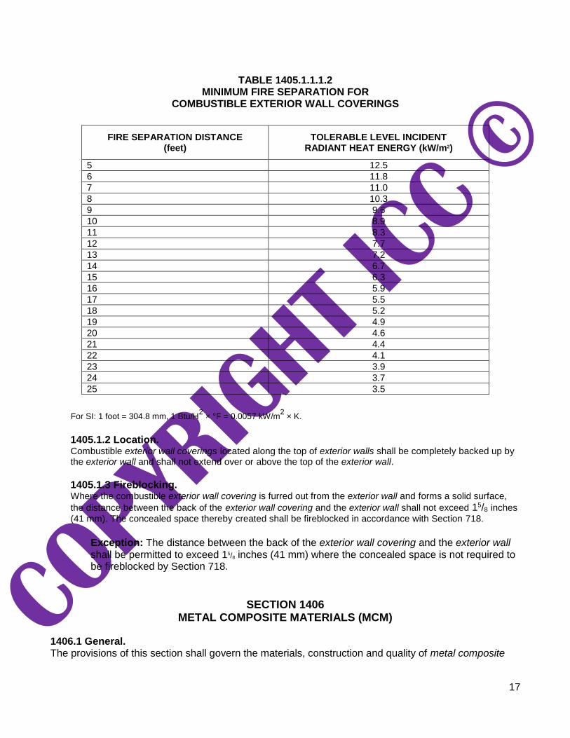
1405.1.1.1.2 Fire separation greater than 5 feet. For fire separation distances greater than 5 feet (1524 mm), any exterior wall covering shall be permitted that has been exposed to a reduced level of incident radiant heat flux in accordance with the NFPA 268 test method without exhibiting sustained flaming. The minimum fire separation distance required for the exterior wall covering shall be determined from Table 1405.1.1.1.2 based on the maximum tolerable level of incident radiant heat flux that does not cause sustained flaming of the exterior wall covering.
17
TABLE 1405.1.1.1.2 MINIMUM FIRE SEPARATION FOR
COMBUSTIBLE EXTERIOR WALL COVERINGS
FIRE SEPARATION DISTANCE (feet)
TOLERABLE LEVEL INCIDENT RADIANT HEAT ENERGY (kW/m2)
5 12.5
6 11.8
7 11.0
8 10.3
9 9.6
10 8.9
11 8.3
12 7.7
13 7.2
14 6.7
15 6.3
16 5.9
17 5.5
18 5.2
19 4.9
20 4.6
21 4.4
22 4.1
23 3.9
24 3.7
25 3.5
For SI: 1 foot = 304.8 mm, 1 Btu/H2 × °F = 0.0057 kW/m
2 × K.
1405.1.2 Location. Combustible exterior wall coverings located along the top of exterior walls shall be completely backed up by the exterior wall and shall not extend over or above the top of the exterior wall.
1405.1.3 Fireblocking. Where the combustible exterior wall covering is furred out from the exterior wall and forms a solid surface,
the distance between the back of the exterior wall covering and the exterior wall shall not exceed 15/8 inches
(41 mm). The concealed space thereby created shall be fireblocked in accordance with Section 718.
Exception: The distance between the back of the exterior wall covering and the exterior wall shall be permitted to exceed 15/8 inches (41 mm) where the concealed space is not required to be fireblocked by Section 718.
SECTION 1406 METAL COMPOSITE MATERIALS (MCM)
1406.1 General. The provisions of this section shall govern the materials, construction and quality of metal composite

18
materials (MCM) for use as exterior wall coverings in addition to other applicable requirements of Chapters 14 and 16. 1406.2 Exterior wall covering. MCM used as exterior wall covering or as elements of balconies and similar projections and bay and oriel windows to provide cladding or weather resistance shall comply with Sections 1406.4 through 1406.13 . 1406.3 Architectural trim and embellishments. MCM used as architectural trim or embellishments shall comply with Sections 1406.7 through 1406.13 . 1406.4 Structural design. MCM systems shall be designed and constructed to resist wind loads as required by Chapter 16 for components and cladding. 1406.5 Approval. Results of approved tests or an engineering analysis shall be submitted to the building official to verify compliance with the requirements of Chapter 16 for wind loads. 1406.6 Weather resistance. MCM systems shall comply with Section 1402 and shall be designed and constructed to resist wind and rain in accordance with this section and the manufacturer’s installation instructions. 1406.7 Durability. MCM systems shall be constructed of approved materials that maintain the performance characteristics required in Section 1406 for the duration of use. 1406.8 Fire-resistance rating. Where MCM systems are used on exterior walls required to have a fire-resistance rating in accordance with Section 705, evidence shall be submitted to the building official that the required fire-resistance rating is maintained.
Exception: MCM systems that are part of an exterior wall envelope not containing foam plastic insulation and are installed on the outer surface of a fire-resistance-rated exterior wall in a manner such that the attachments do not penetrate through the entire exterior wall assembly, shall not be required to comply with this section.
1406.9 Surface-burning characteristics. Unless otherwise specified, MCM shall have a flame spread index of 75 or less and a smoke-developed index of 450 or less when tested in the maximum thickness intended for use in accordance with ASTM E84 or UL 723. 1406.10 Types I, II, III and IV construction. Where installed on buildings of Types I, II, III and IV construction, metal composite material (MCM) shall comply with Sections 1406.10.1 and 1406.10.2 for installations up to 40 feet (12 192 mm) above grade plane. Where installed on buildings of Types I, II, III and IV construction, MCMs and MCM systems shall comply with Sections 1406.10.1 through 1406.10.3, for installations greater than 40 feet (12 192 mm) above grade plane.
1406.10.1 Surface-burning characteristics. MCM shall have a flame spread index of not more than 25 and a smoke-developed index of not more than 450 when tested in the maximum thickness intended for use in accordance with ASTM E84 or UL 723.

19
1406.10.2 Thermal barriers. MCM shall be separated from the interior of a building by an approved thermal barrier consisting of 1/2-inch (12.7 mm) gypsum wallboard or material that is tested in accordance with and meets the acceptance criteria of both the Temperature Transmission Fire Test and the Integrity Fire Test of NFPA 275.
Exceptions:
1. The MCM system is specifically approved based on tests conducted in accordance
with NFPA 286 and with the acceptance criteria of Section 803.1.1.1, UL 1040 or UL 1715. Such testing shall be performed with the MCM in the maximum thickness intended for use. The MCM system shall include seams, joints and other typical details used in the installation and shall be tested in the manner intended for use.
2. The MCM is used as elements of balconies and similar projections, architectural trim
or embellishments.
1406.10.3 Full-scale tests. The MCM system shall be tested in accordance with, and comply with, the acceptance criteria of NFPA 285. Such testing shall be performed on the MCM system with the MCM in the maximum thickness intended for use.
1406.11 Type V construction. MCM shall be permitted to be installed on buildings of Type V construction.
1406.12 Foam plastic insulation. Where MCM systems are included in an exterior wall envelope containing foam plastic insulation, the exterior wall envelope shall also comply with the requirements of Section 2603. 1406.13 Labeling. MCM shall be labeled in accordance with Section 1703.5.
SECTION 1407
EXTERIOR INSULATION AND FINISH SYSTEMS (EIFS)
1407.1 General. The provisions of this section shall govern the materials, construction and quality of exterior insulation and finish systems (EIFS) for use as exterior wall coverings in addition to other applicable requirements of Chapters 7, 14, 16, 17 and 26. 1407.2 Performance characteristics. EIFS shall be constructed such that it meets the performance characteristics required in ASTM E2568.
[BS] 1407.3 Structural design. The underlying structural framing and substrate shall be designed and constructed to resist loads as required by Chapter 16. 1407.4 Weather resistance. EIFS shall comply with Section 1402 and shall be designed and constructed to resist wind and rain in accordance with this section and the manufacturer’s application instructions.
20
1407.4.1 EIFS with drainage. EIFS with drainage shall have an average minimum drainage efficiency of 90 percent when tested in accordance the requirements of ASTM E2273 and is required on framed walls of Type V construction, Group R1, R2, R3 and R4 occupancies.
1407.4.1.1 Water-resistive barrier. For EIFS with drainage, the water-resistive barrier shall comply with Section 1403.2 or ASTM E2570.
1407.5 Installation. Installation of the EIFS and EIFS with drainage shall be in accordance with the EIFS manufacturer’s instructions. 1407.6 Special inspections. EIFS installations shall comply with the provisions of Sections 1704.2 and 1705.17 .
SECTION 1408
HIGH-PRESSURE DECORATIVE EXTERIOR- GRADE COMPACT LAMINATES (HPL)
1408.1 General. The provisions of this section shall govern the materials, construction and quality of High-Pressure Decorative Exterior-Grade Compact Laminates (HPL) for use as exterior wall coverings in addition to other applicable requirements of Chapters 14 and 16. 1408.2 Exterior wall covering. HPL used as exterior wall covering or as elements of balconies and similar projections and bay and oriel windows to provide cladding or weather resistance shall comply with Sections 1408.4 through 1408.14. 1408.3 Architectural trim and embellishments. HPL used as architectural trim or embellishments shall comply with Sections 1408.7 through 1408.14.
[BS] 1408.4 Structural design. HPL systems shall be designed and constructed to resist wind loads as required by Chapter 16 for components and cladding. 1408.5 Approval. Results of approved tests or an engineering analysis shall be submitted to the building official to verify compliance with the requirements of Chapter 16 for wind loads. 1408.6 Weather resistance. HPL systems shall comply with Section 1402 and shall be designed and constructed to resist wind and rain in accordance with this section and the manufacturer’s instructions. 1408.7 Durability. HPL systems shall be constructed of approved materials that maintain the performance characteristics required in Section 1408 for the duration of use. 1408.8 Fire-resistance rating. Where HPL systems are used on exterior walls required to have a fire-resistance rating in accordance

21
with Section 705, evidence shall be submitted to the building official that the required fire-resistance rating is maintained.
Exception: HPL systems not containing foam plastic insulation, which are installed on the outer surface of a fire-resistance-rated exterior wall in a manner such that the attachments do not penetrate through the entire exterior wall assembly, shall not be required to comply with this section.
1408.9 Surface-burning characteristics. Unless otherwise specified, HPL shall have a flame spread index of 75 or less and a smoke-developed index of 450 or less when tested in the minimum and maximum thicknesses intended for use in accordance with ASTM E84 or UL 723. 1408.10 Types I, II, III and IV construction. Where installed on buildings of Types I, II, III and IV construction, HPL systems shall comply with Sections 1408.10.1 through 1408.10.4, or Section 1408.11.
1408.10.1 Surface-burning characteristics. HPL shall have a flame spread index of not more than 25 and a smoke-developed index of not more than 450 when tested in the minimum and maximum thicknesses intended for use in accordance with ASTM E84 or UL 723.
1408.10.2 Thermal barriers. HPL shall be separated from the interior of a building by an approved thermal barrier consisting of 1/2-inch (12.7 mm) gypsum wallboard or a material that is tested in accordance with and meets the acceptance criteria of both the Temperature Transmission Fire Test and the Integrity Fire Test of NFPA 275.
1408.10.3 Thermal barrier not required. The thermal barrier specified for HPL in Section 1408.10.2 is not required where:
1. The HPL system is specifically approved based on tests conducted in accordance with
NFPA 286, and with the acceptance criteria of Section 803.1.1.1, or with UL 1040 or UL 1715. Such testing shall be performed with the HPL in the minimum and maximum thicknesses intended for use. The HPL system shall include seams, joints and other typical details used in the installation and shall be tested in the manner intended for use.
2. The HPL is used as elements of balconies and similar projections, architectural trim or
embellishments.
1408.10.4 Full-scale tests. The HPL system shall be tested in accordance with, and comply with, the acceptance criteria of NFPA 285. Such testing shall be performed on the HPL system with the HPL in the minimum and maximum thicknesses intended for use.
1408.11 Alternate conditions. HPL and HPL systems shall not be required to comply with Sections 1408.10.1 through 1408.10.4 provided that such systems comply with Section 1408.11.1.
1408.11.1 Installations up to 40 feet in height. HPL shall be permitted to be installed up to 40 feet (12 190 mm) in height above grade plane where installed in accordance with Section 1408.11.1.1 or 1408.11.1.2.

22
1408.11.1.1 Fire separation distance of 5 feet or less. Where the fire separation distance is 5 feet (1524 mm) or less, the area of HPL shall not exceed 10 percent of the exterior wall surface.
1408.11.1.2 Fire separation distance greater than 5 feet. Where the fire separation distance is greater than 5 feet (1524 mm), the area of exterior wall surface coverage using HPL shall not be limited.
1408.12 Type V construction. HPL shall be permitted to be installed on buildings of Type V construction. 1408.13 Foam plastic insulation. HPL systems containing foam plastic insulation shall comply with the requirements of Section 2603.
1408.14 Labeling. HPL shall be labeled in accordance with Section 1703.5.
SECTION 1409 PLASTIC COMPOSITE DECKING
1409.1 Plastic composite decking. Exterior deck boards, stair treads, handrails and guards constructed of plastic composites, including plastic lumber, shall comply with Section 2612.