Embed Size (px)
Citation preview

1
Chapter 12
Access and
Interconnection Technologies

2
Internet Access Technology: Upstream and Downstream
• Internet access technology refers to a data communications system that connects an Internet subscriber to an ISP – such as a telephone company or cable company
• How is access technology designed? • Most Internet users follow an asymmetric pattern
– a subscriber receives more data from the Internet than sending • a browser sends a URL that comprises a few bytes • in response, a web server sends content

3
Narrowband and Broadband Access Technologies
• A variety of technologies are used for Internet access • They can be divided into two broad categories based on the
data rate they provide – Narrowband – Broadband

4
Narrowband Access Technologies – Refers to technologies that deliver data at up to 128 Kbps – For example, the maximum data rate for dialup noisy phone lines is
56 Kbps and classified as a narrowband technology

5
Broadband Access Technologies – generally refers to technologies that offer high data rates, but the
exact boundary between broadband and narrowband is blurry • many suggest that broadband technologies deliver more than 1 Mbps • but this is not always the case, and may mean any speed higher than dialup

6
The Local Loop and ISDN • Local loop describes the physical connection between a
telephone company Central Office (CO) and a subscriber – consists of twisted pair and dialup call with 4 KHz of bandwidth
• It often has much higher bandwidth; a subscriber close to a CO may be able to handle frequencies above 1 MHz
• Integrated Services Digital Network (ISDN) – ISDN offers three separate digital channels – designated B, B, and D (usually written 2B + D)
• The 2 B channels (each 64 Kbps) are intended to carry digitized voice, data, or compressed video – Both of the B channels can be combined or bonded to produce a
single channel with an effective data rate of 128 Kbps
• The D channel (16 Kbps) is used as a control channel

7
Digital Subscriber Line (DSL) Technologies
• DSL is one of the main technologies used to provide high-speed data communication services over a local loop

Asymmetrical Digital Subscriber Line (ADSL)
• link between subscriber and network
• uses currently installed twisted pair cable
• is Asymmetric - bigger downstream than up
• uses Frequency division multiplexing
• has a range of up to 5.5km
http://www.cs.tut.fi/tlt/stuff/adsl/node6.html#kuspektri

9
Digital Subscriber Line (DSL) Technologies
• ADSL is the most widely deployed variant – and the one that most residential customers use
• ADSL uses FDM to divide the bandwidth of the local loop into three regions – one of the regions corresponds to traditional analog phone service,
which is known as Plain Old Telephone Service (POTS) – and two regions provide data communication
286 separate frequencies called sub-channels 254+2 (sub-channels allocated for downstream data transmission 31 allocated for upstream data transmission

10
Local Loop Characteristics and Adaptation
• ADSL technology is complex – because no two local loops have identical electrical characteristics
• ADSL is adaptive – That is, when a pair of ADSL modems are powered on, they probe
the line between them to find its characteristics – agree to communicate using techniques that are optimal for the line
• ADSL uses Discrete Multi Tone modulation (DMT) – that combines frequency division multiplexing and inverse
multiplexing techniques – Let’s see how….

Discrete Multitone (DMT) • A multiplexing technique commonly found in digital subscriber line (DSL) systems • The basic idea of DMT is to split the available bandwidth into a large number of
subchannels – DMT then combines hundreds of different signals, or subchannels, into one stream
• Each subchannel is quadrature amplitude modulated (QAM) – if SNR is good – Recall: eight phase angles, four with double amplitudes
• The DMT line code, as defined in ANSI T1.413-1998, divides the useful bandwidth of the standard two wire copper medium used in the PSTN,
– which is 0 to 1104kHz, into 256 separate 4.3125kHz wide bins – Each is called sub-carriers – Each sub-carrier is associated with a discrete frequency or tone, – Each tone has a frequency of 4.3125kHz * n, where n = 1 to 256, and is essentially a
single distinct data channel (total of 1056 KHz)
© 2009 Pearson Education Inc., Upper Saddle River, NJ. All rights reserved. 11

Discrete Multitone (DMT) – Better channel Utilization
• Another demultiplexing technique • Idea: If some subchannel can not carry any data, it can be turned off and
the use of available bandwidth is optimized
http://www.cs.tut.fi/tlt/stuff/adsl/node22.html#kudmtex
High attenuation at higher frequencies

13
Local Loop Characteristics and Adaptation
• Two of the upstream channels are reserved for control information
• Upstream: – A maximum of 255 sub-carriers can be used to modulate data in the
downstream direction – Sub-carrier 256, the downstream Nyquist frequency, and sub-carrier
64, the downstream pilot frequency, are not available for user data • Downstream
– maximum of 31 low frequency sub-carriers can be used to modulate data in the upstream direction
– Sub-carrier 32, the upstream Nyquist frequency, and sub-carrier 16, the upstream pilot frequency, are again not available for user data, limiting the total number of available upstream sub-carriers to 30

14
Local Loop Characteristics and Adaptation
• There is a separate modem running on each sub-channel, which has its own modulated carrier – Carriers are spaced at 4.1325 KHz intervals to keep the signals from
interfering with one another • Two ends assess the signal quality at each frequency
– Use the quality to select a modulation scheme – If a particular frequency has a high signal-to-noise ratio
• ADSL selects a modulation scheme that encodes many bits per baud – If the quality on a given frequency is low
• ADSL selects a modulation scheme that encodes fewer bits per baud

15
The Data Rate of ADSL • How fast can ADSL operate? ADSL can achieve
– a downstream rate of 8.448 Mbps on short local loops – and an upstream rate of 640 Kbps
• Network control channel requires 64 Kbps • The effective upstream rate for user data is 576 Kbps
• ADSL2 can download at close to 20 Mbps • Adaptation has an interesting property
– ADSL does not guarantee a data rate – ADSL can only guarantee to do as well as line conditions allow
• Those farther from a CO (or local loop passes near sources of interference) lower data rates than subscribers who live near the CO (or a local loop does not pass near sources of interference) thus – the downstream rate varies from 32 Kbps to 8.448 Mbps – the upstream rate varies from 32 to 640 Kbps

16
ADSL Installation and Splitters
• Analog phones operate at frequencies below 4 KHz – lifting a receiver can generate noise that interferes with DSL signals
• ADSL uses an FDM device known as a splitter – It divides the bandwidth by passing low frequencies to one output
and high frequencies to another – A splitter is passive; it does not require power – A splitter is usually installed at the location where the local loop
enters a residence or business
• A variation of ADSL wiring (DSL-lite) has become popular – it does not require a splitter to be installed on the incoming line – a subscriber can install DSL by plugging a splitter into a wall jack and
plugging a telephone into the splitter

ADSL Installation and Splitters
17

High-bit-rate Digital Subscriber Line (HDSL) – Connecting the subscriber to the PSTN
http://www.thenetworkencyclopedia.com/d2.asp?ref=872
V.35 is a high-speed serial interface designed to support both higher data rates and connectivity between DTEs (data-terminal equipment) or DCEs (data-communication equipment) over digital lines

19
Cable Modem Technologies • A variety of wireless and wired technologies have been developed for use in the local loop • An alternative access technology that uses the wiring already in place for cable television • It is also known as Community Antenna TeleVision (CATV)
– SCATV – Satellite
• It uses FDM to deliver TV signals over coaxial cable – CATV is not available in all countries
• Coaxial cable has high bandwidth and is less susceptible to electromagnetic interference than twisted pair
For Channels and Frequencies refer to: http://www.jneuhaus.com/fccindex/cablech.html

20
The Data Rate of Cable Modems • How fast can a cable modem operate?
– In theory, a cable system can support data rates of 52 Mbps downstream and 512 Kbps upstream.
– Much faster than DSL!
• In practice, the rate can be much less • The data rate of a cable modem only pertains to
communication between the local cable office and the subscriber's site
• The bandwidth is shared among a set of N subscribers (the size of the set is controlled by the cable provider) – sharing the bandwidth with other subscribers can be a disadvantage
• because the effective data rate available to each individual subscriber varies over time
– if N subscribers share a single frequency • the amount of capacity available to an individual subscriber will be 1/N

CATV Distribution

22
Hybrid Fiber Coax (HFC)
• HFC can provide high-speed data communications – a HFC system uses a combination of optical fibers and coaxial cables – fiber used for the central facilities and coax used for connections to
individual subscribers
• An HFC system is hierarchical – It uses fiber optics for the portions that require the highest bandwidth – and it uses coax for parts that can tolerate lower data rates
• Trunk to refer to the high-capacity connections between the cable office and each neighborhood area
• Feeder circuit to refer to the connection to an individual subscriber – Trunk connections can be up to 15 miles long – Feeder circuits are usually less than a mile

Hybrid Fiber Coax
23
Feeder circuit
Trunk

24
Access Technologies That Employ Optical Fiber
• There are available a variety of technologies that either employ optical fiber in a hybrid system or deploy optical fiber all the way to each subscriber

25
Access Technologies That Employ Optical Fiber
• Fiber To The Curb (FTTC) – it uses optical fiber for high capacity trunks – the idea is to run optical fiber close to the end subscriber – and then use copper for the feeder circuits – it uses two media in each feeder circuit to allow the cable system to provide an
additional service, such as voice • Fiber To The Building (FTTB)
– it will use optical fiber to allow high upstream data rates for businesses • Fiber To The Home (FTTH)
– uses optical fiber to deliver higher downstream data rates to residential subscribers – The emphasis is on many channels of entertainment and video
• Fiber To The Premises (FTTP) – A generic term, FTTP, encompasses both FTTB and FTTH

FTTH
The Fiber to the Home technology is capable of supporting speeds up to 1000Mbps.

PON Supporting FTTH

Wireless Access Technologies
28
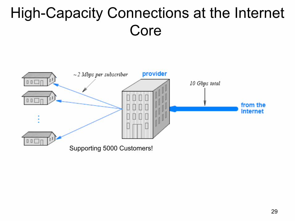
High-Capacity Connections at the Internet Core
29
Supporting 5000 Customers!

30
High-Capacity Connections at the Internet Core
• What wire-based technology can a provider use to move data a long distance at a rate of 10 Gbps? – The answer lies in a point-to-point digital circuit leased from a
telephone company – High-capacity digital circuits are available for a monthly fee, and can
be used to transfer data
• Telephone companies have the authority to install wiring that crosses municipal streets
• A circuit can extend between two buildings, across a city, or from a location in one city to a location in another – The fee charged depends on the data rate of the circuit and the
distance spanned – This is referred to as leased digital circuit

31
Circuit Termination, DSU/CSU, • To use a leased digital circuit,
one must agree to follow the rules of the telephone system – including adhering to the standards
that were designed for transmitting digitized voice
DSU/CSU

32
Circuit Termination, DSU/CSU, • Computer industry and the telephone industry
developed independently – Standards for telephone system digital circuits differ from
those used in the computer industry – A special piece of hardware is needed to interface a
computer to a digital circuit provided by a telephone company
– Known as a Data Service Unit/Channel Service Unit (DSU/CSU)
• Device contains two functional parts, usually combined into a single chassis
– The CSU portion of the DSU/CSU device handles line termination and diagnostics

33
Circuit Termination, DSU/CSU • A CSU also contains a loopback test facility
– that allows the CSU to transmit a copy of all data that arrives across the circuit back to the sender without further processing
• We need to prevent excessive 1s – having too many contiguous 1 bits would mean excessive current on
the cable – To prevent problems, a CSU can either use
• an encoding that guarantees a balance (e.g., a differential encoding) • or a technique known as bit stuffing
• The DSU portion of a DSU/CSU handles the data – It translates data between the digital format used on the carrier's
circuit and the digital format required by the customer's computer

Circuit Termination, DSU/CSU • The interface standard used on the computer side depends
on the rate that the circuit operates – If the data rate is less than 56 Kbps, the computer can use RS-232 – For rates above 56 Kbps, the computer must use interface hardware
that supports higher speeds (e.g., use RS-449 or V.35 standards)
35
Telephone Standards for Digital Circuits • A digital circuit leased from a telco follows the same digital
transmission standards that the telco uses to transport digital phone calls
• In the USA, standards for digital telephone circuits were given names that consist of the letter T followed by a number – One of the most popular is known as T1 – Many small businesses use a T1 circuit to carry data
• T-standards are not universal – Japan adopted a modified version of the T-series standards – Europe chose a slightly different scheme; it uses the letter E

Telephone Standards for Digital Circuits
36

37
DS Terminology and Data Rates • The data rates of T standards have been chosen so they
can each handle multiple voice calls – Note that the capacity of circuits does not increase linearly with their
numbers – For example, the T3 standard defines a circuit with much more than
three times the capacity of T1
• Telcos may lease circuits with lower capacity than those listed in the figure – they are known as fractional T1 circuits
• To multiplex multiple phone calls onto a single connection – known as Digital Signal Level standards or DS standards
• For example, DS1 denotes a service that can multiplex 24 phone calls onto a single circuit

38
Highest Capacity Circuits (STS Standards)
• Telephone companies use the term trunk – to denote a high-capacity circuit, and have created a series of
standards for digital trunk circuits
• Synchronous Transport Signal (STS) standards specify the details of high-speed connections

Highest Capacity Circuits (STS Standards)
39

40
The C Suffix • The STC and OC terminology described above has one
additional feature – an optional suffix of the letter C, which stands for concatenated
• The suffix denotes a circuit with no inverse multiplexing – an OC-3 circuit can consist of three OC-1 circuits operating at 51.840
Mbps each – or it can consist of a single OC-3C (STS-3C) circuit that operates at
155.520 Mbps
• Is a single circuit operating at full speed better than multiple circuits operating at lower rates? – The answer depends on how the circuit is being used
• In general, having a single circuit operating at full capacity provides more flexibility – and eliminates the need for inverse multiplexing equipment

41
Synchronous Optical NETwork (SONET) • Telcos defined a broad set of standards for digital
transmission – In North America, the standards are known by the term Synchronous
Optical NETwork (SONET) – In Europe they are known as the Synchronous Digital Hierarchy (SDH)
• SONET specifies some details, such as – how data is framed – how lower-capacity circuits are multiplexed into a high-capacity circuit – how synchronous clock information is sent along with data

SONET Ring and CATV
From the Provider

Interesting Tests • Try the following link to check your uplink/downlink speed:
– http://myspeed.visualware.com/index.php
• You can also download: – http://download.visualware.com/networkmonitoring/index.html – Download vrle.exe
43