Embed Size (px)
Citation preview

1Chapter 12
Chapter 12Surface Texture Symbols
2Learning Objectives
L Explain common terms related to surface quality and surfacetexture symbols.
L Identify and interpret the components of surface texturesymbols.
L Identify lay symbols used in surface texture symbols.L Describe the units used by various values within surface texture
symbols.
Learning Objectives
3Learning Objectives
L Explain standard practices for applying surface texturesymbols on a print.
L Identify special designations related to surface qualitythat may appear on a print.
Learning Objectives
4Surface Texture Terms
L Surface texture is the overall roughness, waviness, lay,or flaws of a surface
Surface Texture Terms
5Surface Texture Terms
L Roughness height examples
Surface Texture Terms
6Surface Texture Symbols
L In the past, finished surfaces were identified with finishmarks, as shown here
L Surface texture symbols are now used instead
Surface Texture Symbols

7Surface Texture Symbol
L A—Basic surface texture symbolL B—Material removal is required by machiningL C—Indicates a minimum amount that must be removedL D—Material removal is prohibitedL E—Horizontal bar to help locate parameters and values
Surface Texture Symbol
8Surface Texture Values
L (a) Average roughness value (microinches or micrometers)L (b) Optional production method (such as GRIND)L (c) Roughness cutoff or sampling lengthL (d) Optional lay symbolL (e) Minimum material removal (inches or millimeters)L (f) Roughness parameter other than arithmetic average
Surface Texture Values
9Lay Symbols
L Lay symbols are not required
L Seven options
Lay Symbols
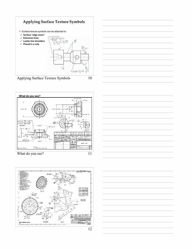
10Applying Surface Texture Symbols
L Surface texture symbols can be attached to:T Surface “edge views”T Extension linesT Leader line shouldersT Placed in a note
Applying Surface Texture Symbols
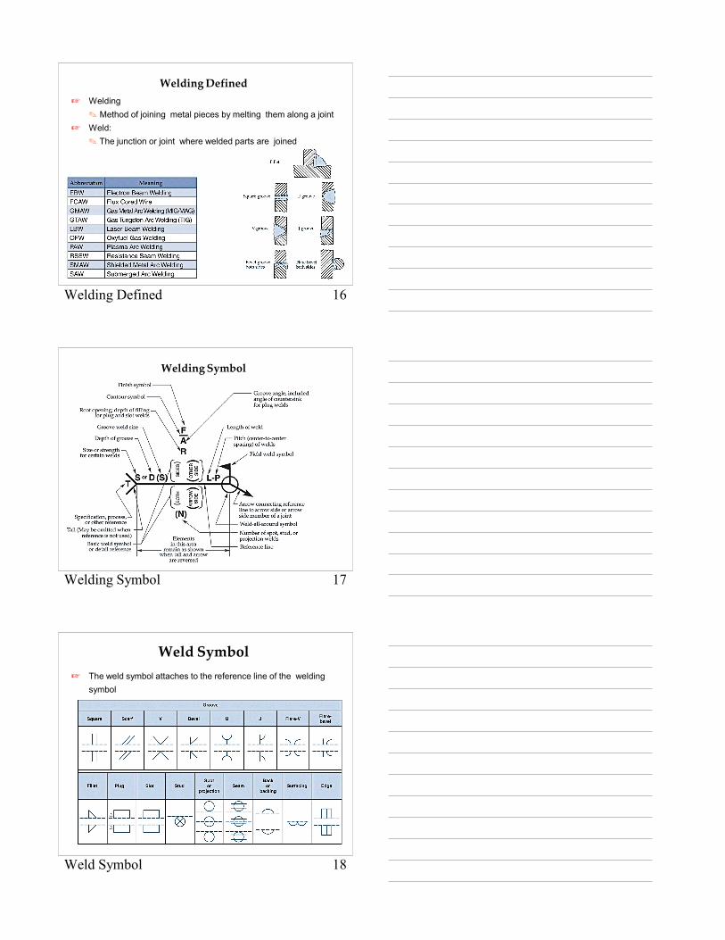
11What do you see?
What do you see?
12

13Chapter 22
Chapter 22Welding Prints
14Learning Objectives
L Identify a welding symbol.L List the elements of a welding symbol.L Explain the meaning of a welding symbol.L Identify the basic weld symbols used in welding symbols.L Discuss other welding applications.
Learning Objectives
15Welding Prints
L Welding prints combine elements of detail and assemblydrawings within one print
Welding Prints
16Welding Defined
L Welding O Method of joining metal pieces by melting them along a joint
L Weld: O The junction or joint where welded parts are joined
Welding Defined
17Welding Symbol
Welding Symbol
18Weld Symbol
L The weld symbol attaches to the reference line of the weldingsymbol
Weld Symbol

19Weld Location
L Weld location is indicated by the relation of the weld symbol tothe reference line
Weld Location
20Weld Dimensions
L Dimensions of a weld can be specified above or below thereference line or in a general note
Weld Dimensions
21Groove Welds
L Groove weld specificationsT (A) Groove angleT (B) Root opening
Groove Welds

22Spot Weld Examples
L The spot weld symbol can be annotated in many waysT (A) Diameter specifiedT (B) Strength specifiedT (C) Spacing specified
(weld through also)T (D) Quantity specified
Spot Weld Examples
23Supplementary Symbols
L Contour symbolT (A) Flat facedT (B) ConvexT (C) Convex
Supplementary Symbols
24Supplementary Symbols
L Weld all aroundL Field weldL Melt throughT (A) Melt through plus reinforcementT (B) Melt through and finished by machining
Supplementary Symbols
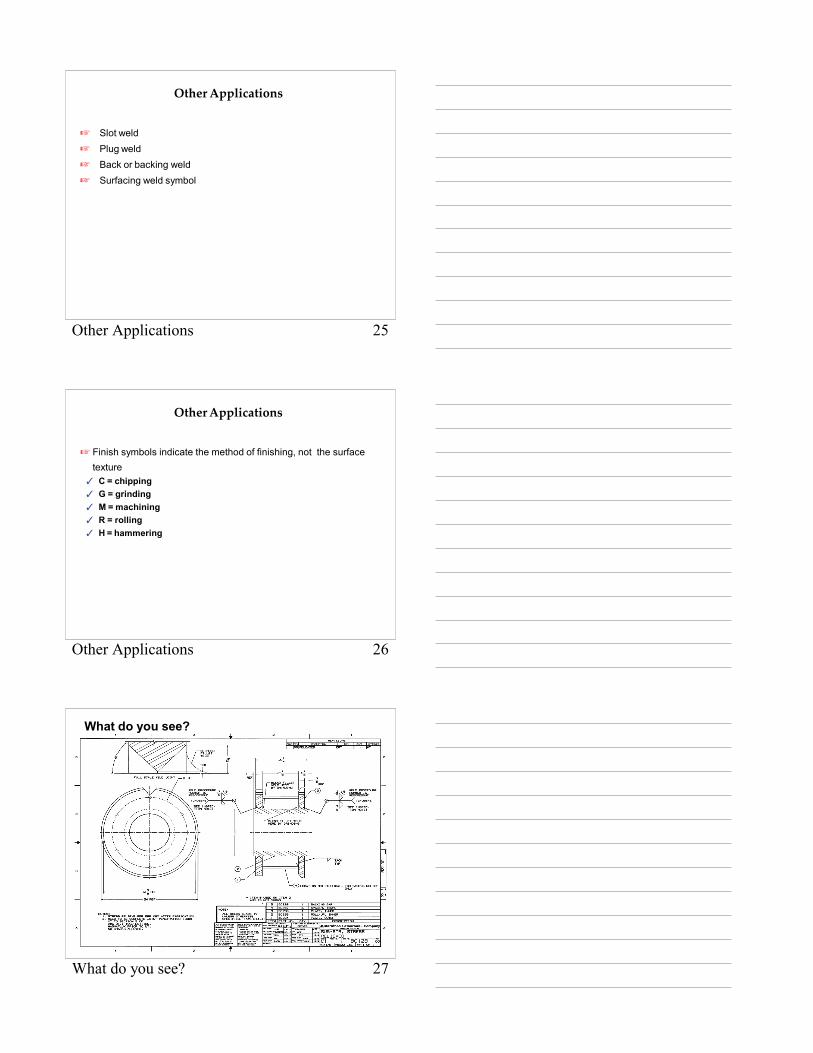
25Other Applications
L Slot weldL Plug weldL Back or backing weldL Surfacing weld symbol
Other Applications
26Other Applications
L Finish symbols indicate the method of finishing, not the surfacetexture
T C = chippingT G = grindingT M = machiningT R = rollingT H = hammering
Other Applications
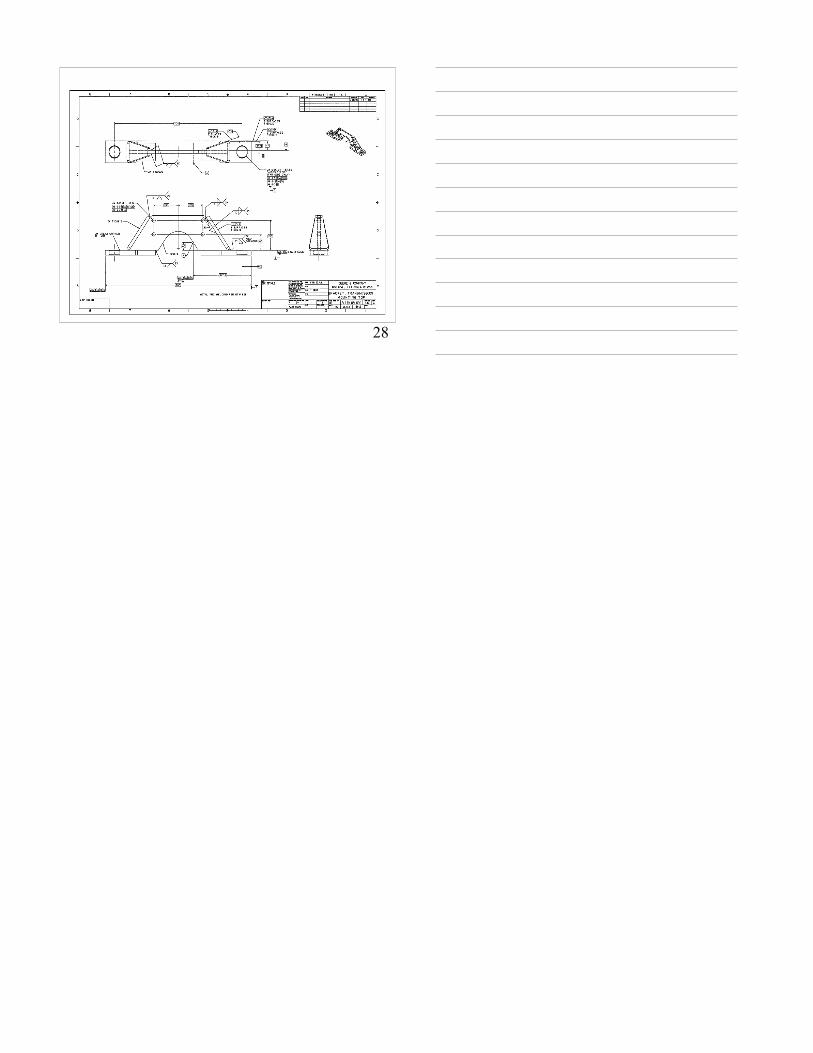
27What do you see?
What do you see?
28