Embed Size (px)
Citation preview
Computer Peripherals
School of Computer Engineering
Nanyang Technological University
Singapore
These notes are part of a 3rd year undergraduate course called "Computer Peripherals", taught at Nanyang Technological University
School of Computer Engineering in Singapore, and developed by Associate Professor Kwoh Chee Keong. The course covered
various topics relevant to modern computers (at that time), such as displays, buses, printers, keyboards, storage devices etc... The
course is no longer running, but these notes have been provided courtesy of him although the material has been compiled from
various sources and various people. I do not claim any copyright or ownership of this work; third parties downloading the material
agree to not assert any copyright on the material. If you use this for any commercial purpose, I hope you would remember where you
found it.
Further reading is suggested at the end of each chapter, however you are recommended to consider a much more modern alternative
reference text as follows:
Computer Architecture: an embedded approach Ian McLoughlin
McGraw-Hill 2011
Chapter 11. Magnetic Tape Drives.
Magnetic tape storage is often the forgotten or ignored peripheral device until the first diskcrash or virus infection. In the early days, when disk storage was small and expensive,magnetic tapes were used for data processing as well as storage. A typical process wouldinclude reading data in from a set of punched cards. These input records are sorted and writtenout to tape. Often the sorting process requires the use of two tape drives to perform the sortmerge operations as internal memory could be quite limited. The sorted input data tape ismounted on one drive, the "old" master tape on the next drive, and the updated output masteron a third drive.
Today the main applications are for archive and backup, where the cost as well asvolume per megabyte is still much lower than any other competing medium.
11.1 Classification and Application of Tape Drives
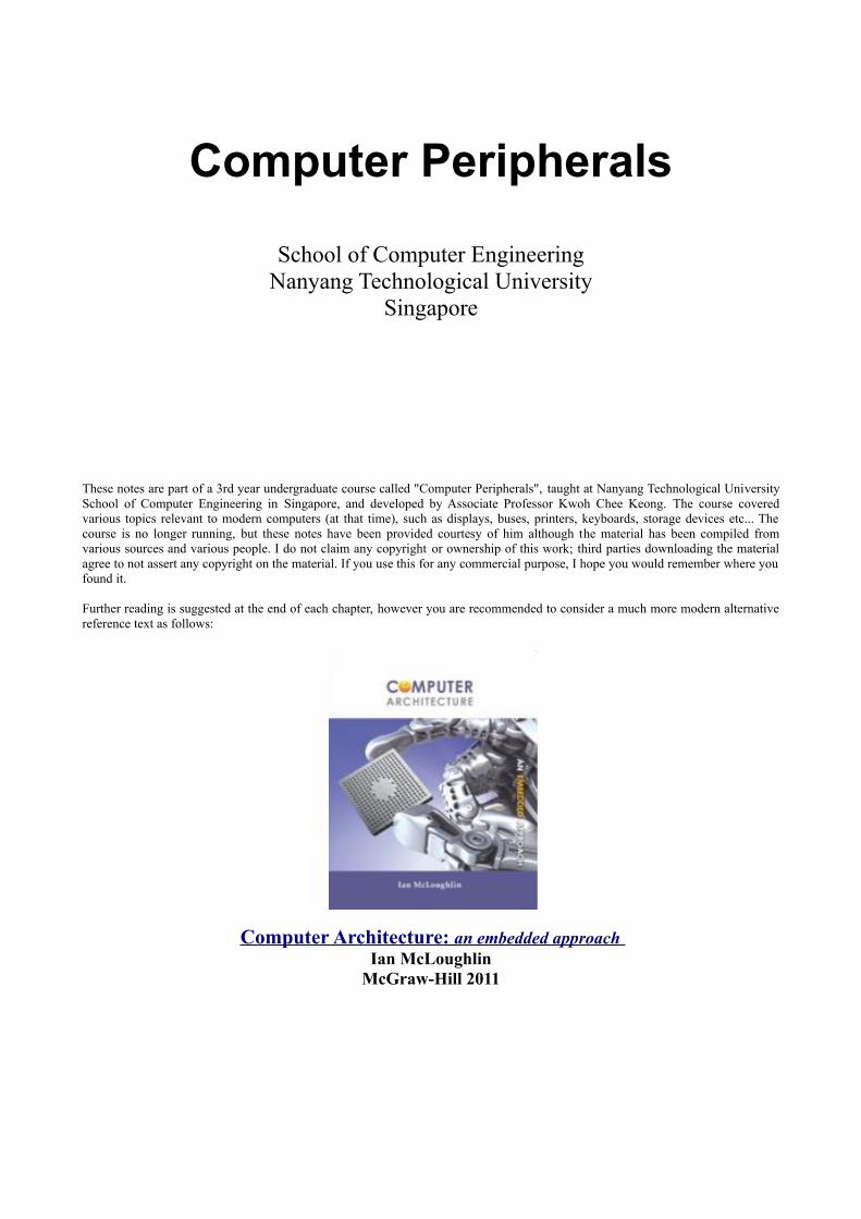
There are several ways of classifying magnetic tape storage devices. One way is to classifythem by the mode of operation, viz. block mode or streaming mode tape drives. Another wayis to divide them according to whether the recording is done by a fixed or a rotating head. Thechart in Figure 0-1 gives a finer classification.
Multi-track parallel Helical scan
1/2" Reel, 9-trackblock / streaming DDS streaming
Multi-track serpentine
Teac / Philips 9-track IBM / Cipher Digital audio tape - ARDAT
QIC Mini-cartridge
Archive QIC 24/150 Irwin QIC 40/80
Exabyte
Video cassettestreaming
Compact cassetteblock / streaming
QIC Cartridgestreaming/block
Magnetic tape
streaming
Figure 0-1. Classification of magnetic tape drives.
www.lintech.org
Magnetic Tape Drives 2
11.1.1 Start-Stop Blocked Mode
In the early years of data processing using computers, tape drives were used for the storage ofdata files on a record-by-record basis. For updating a record or block of data is first read intothe CPU, calculations performed, and an updated record is written back to the tape. Providedthe block length remains the same, the drive would rewind the tape by one block length andthe updated block written back over the old record.
In this blocked mode of operation, data are recorded in fixed physical blocks of 512to 4096 bytes. Between each block there is an Inter-Record Gap (IRG) of up to 0.5 inch. Themagnetic tape controller uses the IRG to locate the beginning of each block and can update orover-write data on the tape on a block by block basis.
Obviously blocked mode operation places a higher demand on the tape transportmechanism. Tape movement now consists a sequences forward, stop, reverse, stop operationsin quick succession. In addition, it has the capability of searching for a specific block byskipping in the forward or reverse directions.
Although blocked mode operation can be implemented on any kind of tape drives, itis usually found only in the large 1/2-inch fixed head multi-track drives and s few mini-cartridge units. In the case of the mini-cartridge units, additional software is used to format thetape into "tracks" and "sectors" so that it emulates a floppy disk drive with a capacity of 20/40Mbytes.
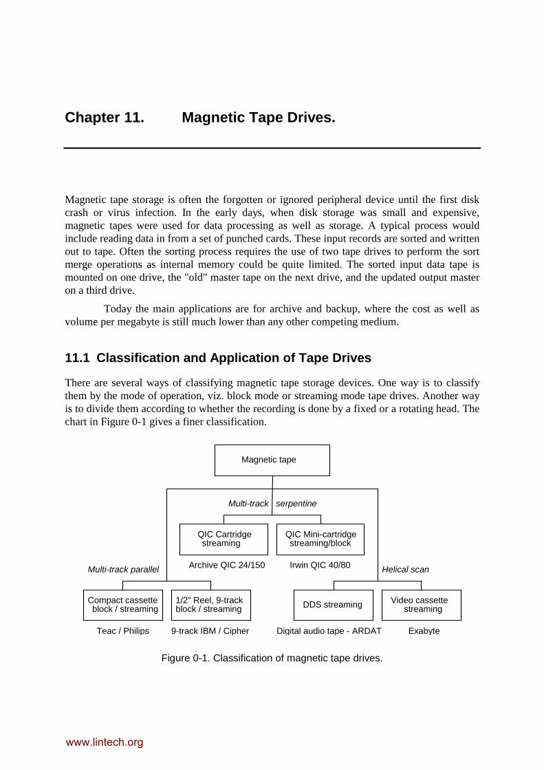
Table 1 gives the typical specifications of some popular IBM blocked mode 1/2-inchtape drives.
Table 1. Typical specifications of IBM reel-to-reel tape drives.
IBM Product No. 726 3420 3480
FCS (First customer shipment) 1953 1973 1985
Linear Density (BPI) 100 6250 38,000
Number of Tracks 7 9 18
Reel Capacity (MB) 2.2 156 200
Data Rate (KBytes/sec) 75 1250 3000
Recording Code NRZI GCR(0,2) GCR(0,3)
Tape Transport Vacuum Vacuum Cartridge
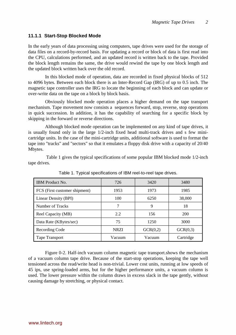
Figure 0-2. Half-inch vacuum column magnetic tape transport.shows the mechanismof a vacuum column tape drive. Because of the start-stop operations, keeping the tape welltensioned across the read/write head is non-trivial. Lower cost units, running at low speeds of45 ips, use spring-loaded arms, but for the higher performance units, a vacuum column isused. The lower pressure within the column draws in excess slack in the tape gently, withoutcausing damage by stretching, or physical contact.
www.lintech.org

Magnetic Tape Drives 3
Erase head
Write headRead head
Capstan
Capstan
Vacuum column
Tape
Figure 0-2. Half-inch vacuum column magnetic tape transport.
11.1.2 Streaming Mode
When the primary application of tape drives is for the archiving and backup, the need tooperate in the start-stop mode is no longer required. In such applications, a file or set of filesare written onto the tape. If these files have changed, the updated versions are normally keptby re-writing the complete files. No attempt is made to update just the affected records withinthe file. In this case streaming mode tape drives can be used. Streaming tapes write completefiles or groups of files as a continuous "stream" of data. Although the actual data may berecorded in physical blocks, there is no support for locating and modifying a particular blockon the tape and leaving the portions before and after unaffected.
Tape motion is controlled only in the forward direction for read, write or skipforward to file mark or end of file. Reverse motion is used only to rewind the tape back to thebeginning. We will consider in turn the two current tape drive mechanisms, the fixed head androtary head machines, both operating in the streaming mode.
11.2 Stationary Head Recorders
The ubiquitous walkman is an audio tape recorder with a stationary head. Early digital tapedrives were adaptations of audio tape recorders. In fact normal audio recorders have been usedfor storing digital data by using the digital information to modulate tone signals in the audiofrequency range. FSK, PSK and other modulation schemes have been used. However, digitaltape drives normally have different designs to optimize data storage density and transfer. Inorder to achieve high storage efficiency, direct digital recording is used. The tape is movedrapidly across the head as the data transfer rate is a direct function of tape speed. Digital tapedrives run the tape at over 45 ips compared the several inches per second for audio units.
As the recording track runs along the length of the tape, several tracks are laid out inparallel. On the multi-track recorders, these tracks are recorded simultaneously using a headblock with a number of recording heads mounted in parallel.
www.lintech.org

Magnetic Tape Drives 4
11.2.1 The QIC Standard
The QIC (Quarter-Inch Cartridge) industry standard describes a stationary head,streaming mode tape storage which is becoming increasingly popular because of its compactsize and large capacity. However it has only two sets of read/write heads, one for eachdirection of tape movement. Parallel tracks are obtained by physically moving the headperpendicularly across the width of the tape to access a new track. Each track is writtensequentially resulting in a serpentine pattern as can be seen in Figure 12.1.
QIC defines a number of standards, differing in capacity, as can be seen in Table 2.
Table 2. QIC tape standards.
QIC-24 QIC-150 QIC-525 QIC-1350
Capacity (formatted) MB 45 or 60 125 or 150 320 or 525 1.35 GB
Track Format 9 18 26 30
Flux Density 10,000 ftpi 12,500 ftpi 20,000 ftpi 38,750 ftpi
Data Density 8,000 bpi 10,000 bpi 16,000 ftpi 51,667 bpi
Tape Speed 90 ips 90 ips 120 ips 120 ips
Data Transfer RateKBytes/Sec
90 112.5 240 600
Recording Code GCR (0,2) GCR (0,2) GCR (0,2) RLL(1,7)
Track Width (in) 0.0135 0.0056 0.0070 0.0070
Tape Length (ft) 450 or 600 600 600 or 1000 750
Soft Error Rate 1 in 108 1 in 108 1 in 108 1 in 108
Hard Error Rate 1 in 1010 1 in 1010 1 in 1010 1 in 1010
11.2.2 QIC-24 Cartridge Tape Drive
We shall use QIC-24 standard to look at the various aspects of the QIC tape drive.Referring again to Figure 0-3 the read/write operation is explained in the following section.
11.2.2.1 Read/Write Operation
1. When the tape is loaded, rewinding takes place. Tape is then forwarded toBeginning of Tape (BOT), and head is positioned for Track 0.
2. On WRITE command, tape is forwarded to the Load Point (LP). This is thebeginning of the recording zone and drive begins writing to tape on Track 0.Data is written bit serial on one track. In addition, during the writing on Track0, the erase head is enabled. Full track erase is performed by applying ACsignal to the erase head ahead of the write head.
www.lintech.org
Magnetic Tape Drives 5
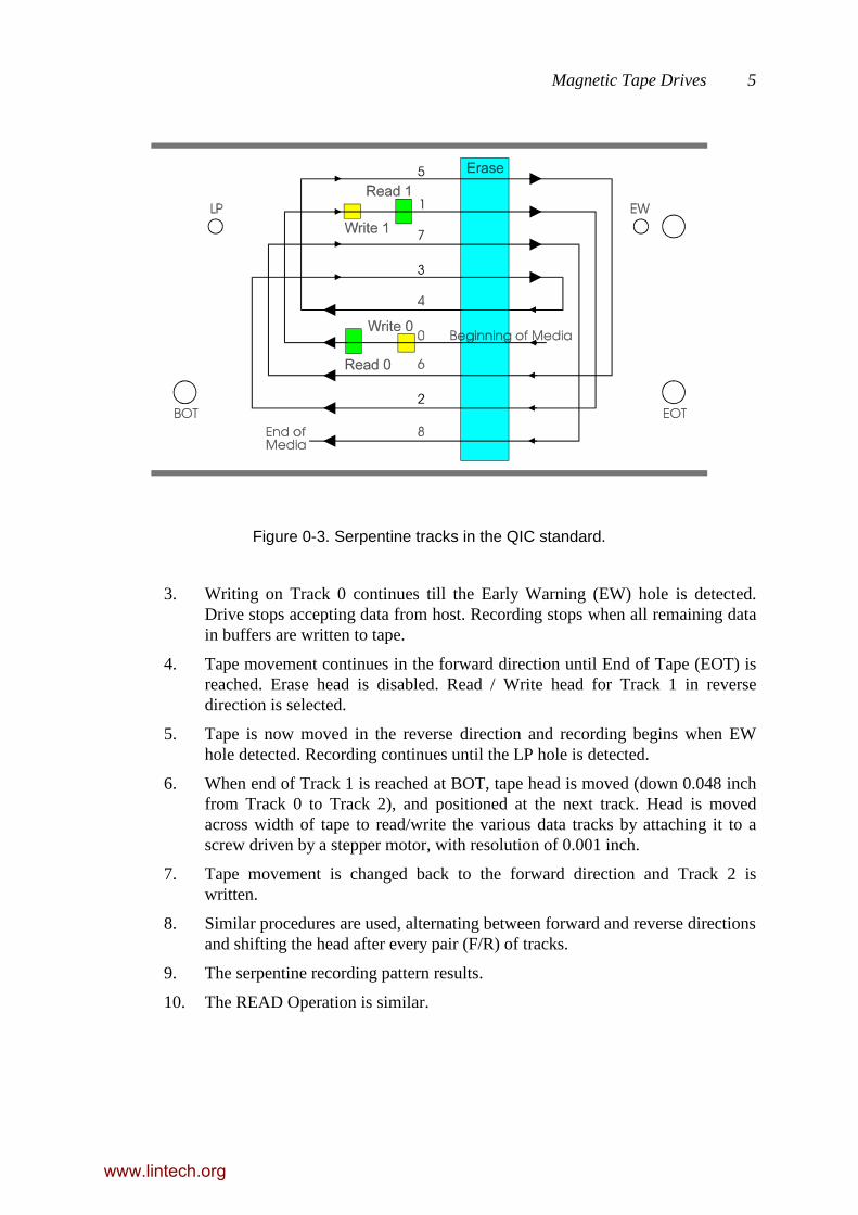
Figure 0-3. Serpentine tracks in the QIC standard.
3. Writing on Track 0 continues till the Early Warning (EW) hole is detected.Drive stops accepting data from host. Recording stops when all remaining datain buffers are written to tape.
4. Tape movement continues in the forward direction until End of Tape (EOT) isreached. Erase head is disabled. Read / Write head for Track 1 in reversedirection is selected.
5. Tape is now moved in the reverse direction and recording begins when EWhole detected. Recording continues until the LP hole is detected.
6. When end of Track 1 is reached at BOT, tape head is moved (down 0.048 inchfrom Track 0 to Track 2), and positioned at the next track. Head is movedacross width of tape to read/write the various data tracks by attaching it to ascrew driven by a stepper motor, with resolution of 0.001 inch.
7. Tape movement is changed back to the forward direction and Track 2 iswritten.
8. Similar procedures are used, alternating between forward and reverse directionsand shifting the head after every pair (F/R) of tracks.
9. The serpentine recording pattern results.
10. The READ Operation is similar.
www.lintech.org
Magnetic Tape Drives 6
11.2.2.2 12.2.1.2. Data Block Format
Data block marker Block addressCRC
1
Byte
s
2
Byte
s
4
Byte
Preamble 512 Bytes of data Postamble
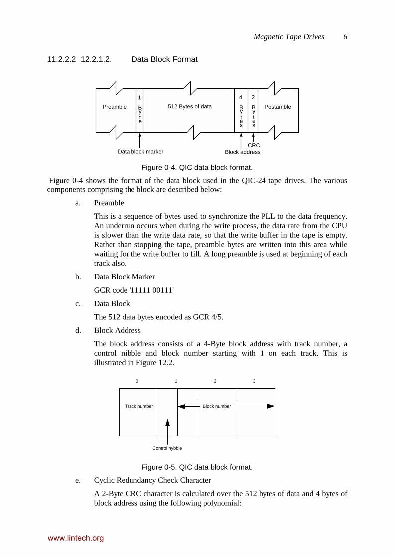
Figure 0-4. QIC data block format.
Figure 0-4 shows the format of the data block used in the QIC-24 tape drives. The variouscomponents comprising the block are described below:
a. Preamble
This is a sequence of bytes used to synchronize the PLL to the data frequency.An underrun occurs when during the write process, the data rate from the CPUis slower than the write data rate, so that the write buffer in the tape is empty.Rather than stopping the tape, preamble bytes are written into this area whilewaiting for the write buffer to fill. A long preamble is used at beginning of eachtrack also.
b. Data Block Marker
GCR code '11111 00111'
c. Data Block
The 512 data bytes encoded as GCR 4/5.
d. Block Address
The block address consists of a 4-Byte block address with track number, acontrol nibble and block number starting with 1 on each track. This isillustrated in Figure 12.2.
Track number
Control nybble
Block number
0 1 2 3
Figure 0-5. QIC data block format.
e. Cyclic Redundancy Check Character
A 2-Byte CRC character is calculated over the 512 bytes of data and 4 bytes ofblock address using the following polynomial:
www.lintech.org
Magnetic Tape Drives 7
CRC = x16 + x12 + x5 + 1
f. Postamble
A normal post amble of 5 - 20 flux transitions are recorded at maximumdensity to act as a guard band. Elongated post ambles of 3500 - 7000 fluxtransitions are appended when an underrun occurs.
11.2.2.3 Underrun
If data from the host are interrupted, or if data transfers from the host drop below 90Kbytes/sec, underrun occurs and duplicate blocks maybe recorded. These duplicate blocks aretransparent to the host.
11.2.2.4 Reliability
The QIC standard has error processing and recovery software incorporated in the firmware.Their operation is transparent to host and user. For each block of 512 bytes of data pluscontrol data, a cyclic redundancy check (CRC) character is computed and recorded. The CRCgenerating polynomial used is:
x16 + x12 + x5 + 1
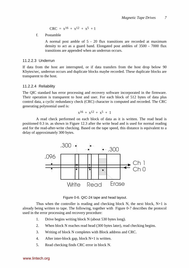
A read check performed on each block of data as it is written. The read head ispositioned 0.3 in. as shown in Figure 12.3 after the write head and is used for normal readingand for the read-after-write checking. Based on the tape speed, this distance is equivalent to adelay of approximately 300 bytes.
Figure 0-6. QIC-24 tape and head layout.
Thus when the controller is reading and checking block N, the next block, N+1 isalready being written to tape. The following, together with Figure 0-7 describes the protocolused in the error processing and recovery procedure:
1. Drive begins writing block N (about 530 bytes long).
2. When block N reaches read head (300 bytes later), read checking begins.
3. Writing of block N completes with Block address and CRC.
4. After inter-block gap, block N+1 is written.
5. Read checking finds CRC error in block N.
www.lintech.org
Magnetic Tape Drives 8
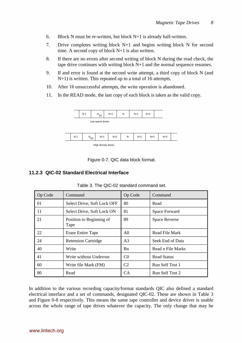
6. Block N must be re-written, but block N+1 is already half-written.
7. Drive completes writing block N+1 and begins writing block N for secondtime. A second copy of block N+1 is also written.
8. If there are no errors after second writing of block N during the read check, thetape drive continues with writing block N+1 and the normal sequence resumes.
9. If and error is found at the second write attempt, a third copy of block N (andN+1) is written. This repeated up to a total of 16 attempts.
10. After 16 unsuccessful attempts, the write operation is abandoned.
11. In the READ mode, the last copy of each block is taken as the valid copy.
N-1 N N+1 N N+1 N+2(e)
N-1 N N+1 N+2 N N+1(e)
N+2 N+3
Low speed drives
High density drives
Figure 0-7. QIC data block format.
11.2.3 QIC-02 Standard Electrical Interface
Table 3. The QIC-02 standard command set.
Op Code Command Op Code Command
01 Select Drive, Soft Lock OFF 80 Read
11 Select Drive, Soft Lock ON 81 Space Forward
21 Position to Beginning ofTape
89 Space Reverse
22 Erase Entire Tape A0 Read File Mark
24 Retension Cartridge A3 Seek End of Data
40 Write Bn Read n File Marks
41 Write without Underrun C0 Read Status
60 Write file Mark (FM) C2 Run Self Test 1
80 Read CA Run Self Test 2
In addition to the various recording capacity/format standards QIC also defined a standardelectrical interface and a set of commands, designated QIC-02. These are shown in Table 3and Figure 0-8 respectively. This means the same tape controller and device driver is usableacross the whole range of tape drives whatever the capacity. The only change that may be
www.lintech.org

Magnetic Tape Drives 9
required is to modify the capacity parameter so that the software can determine when the nextvolume of tape needs to be mounted.
11.2.4 QIC-36 Standard Drive Interface
A low level electrical interface for the tape drive has also been defined as the QIC-36standard. This is basically the electrical and electromechanical interface and does not includeany intelligence in the tape drive electronics. Essentially this specifies the interface betweenthe read/write head, the motors and sensors on the basic tape drive and the drive controller.
Host Tape controller
Tape drive
QIC-36 interface
Databus 0:7
Parity (opt)
On-lineRequestResetTransfer
AcknowledgeReadyExceptionDirection
Ground
QIC-02 Interface
Figure 0-8. The QIC-02 standard electrical interface.
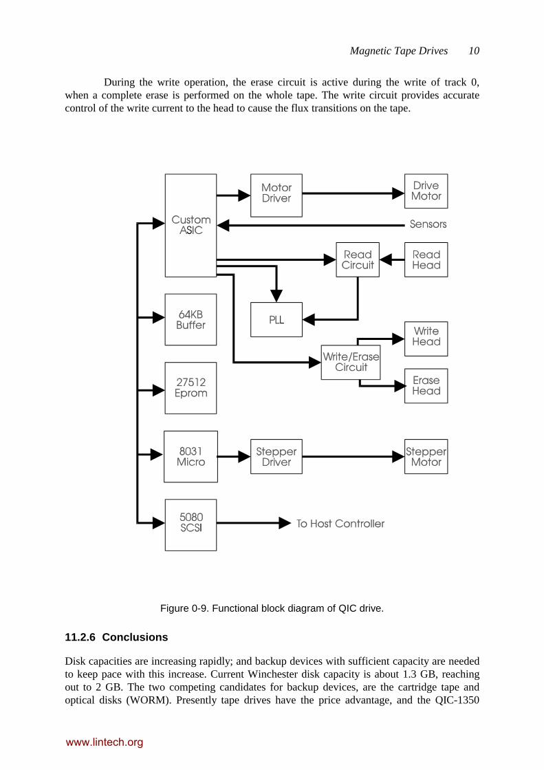
11.2.5 Tape Drive Electronics
Figure 12.4 shows the functional block diagram of a typical QIC tape drive with a SCSIinterface. The 8-bit microprocessor together with the custom VLSI, provides complete controlof the drive. Memory consists of 16 Kbytes of programme in Eprom and 64 Kbytes ofdynamic RAM for buffering. The standard 5080 SCSI controller device operates under thecontrol of the microprocessor, negotiating handshake protocols, commands and data transferwith the host computer. The VLSI brings together a number of functions in one reliablepackage by reducing component count. These are:
• DMA Controller, to handle data transfer from the host through the SCSIcontroller.
• Interrupt Controller
• Memory Access Controller, provides multiplexing of memory and addressbuses, dynamic RAM refresh and parity checking.
• Read/Write Controller, in the write mode performs the read-after-writefunction to verify correct writing of data.
• Clock Generator, provides the various clocks for the microprocessor, SCSIinterface and read/write phase clocks.
• Data Separator; when the data is read from tape, it is a mixture of data andclock signals. The read circuit conditions and detects these signals which arethen passed to the VLSI to be separated, making use of the PLL.
www.lintech.org
Magnetic Tape Drives 10
During the write operation, the erase circuit is active during the write of track 0,when a complete erase is performed on the whole tape. The write circuit provides accuratecontrol of the write current to the head to cause the flux transitions on the tape.
Figure 0-9. Functional block diagram of QIC drive.
11.2.6 Conclusions
Disk capacities are increasing rapidly; and backup devices with sufficient capacity are neededto keep pace with this increase. Current Winchester disk capacity is about 1.3 GB, reachingout to 2 GB. The two competing candidates for backup devices, are the cartridge tape andoptical disks (WORM). Presently tape drives have the price advantage, and the QIC-1350
www.lintech.org

Magnetic Tape Drives 11
tape, with a capacity of 1.35 GB has been designed for this application. Developmentcontinues to continuing increasing this capacity.
11.3 Rotary Head Recorders
Whilst the stationary head recorders are similar on the common audio recorders, the rotaryhead recorders works on the same principles as the video cassette recorders. The two mainstorage devices in this group are based on the video cassette recorders and the newer rotary-head digital audio tape (RDAT). With the multi-track stationary head recorders, tapeutilisation is low as there has to be sufficient separation between the recording tracks toprevent cross-talk interference. Also for high data rates, the tape has to be moved rapidlyacross the heads.
Rotary head recorders overcome this two problems. Instead of moving the tape, thehead is rotating at a high speed across the tape. The tape itself moves slowly at a ratesufficient to feed a new portion to the head as it rotates. In fact, the tracks are allowed tooverlap, and cross-track interference is reduced by offsetting the azimuths of the multipleheads.
The Exabyte EXB-8200 drive uses the video cassette format with 8 mm tape. It has arated storage capacity of 2.5 GB and a data transfer rate of about 246 Kbyte/sec. There are anumber of vendors using the DAT cartridge format with 60 m of 4 mm tape. These have acapacity of 1.3 GB and a sustained data transfer rate of 183 Kbyte/sec. Our discussion willfocus on the DAT devices.
Figure 0-10. Helical scan rotary-head recorder.
Figure 0-10 show the general arrangement of the rotary-head recorder. Four headsare located on the rotating drum, setup as two pairs of write/read heads. Differing from thestandard VCR, the tape is only wrapped around a 90° quadrant of the drum, which is rotatingat 2000 rpm. The tape itself moves forward at about 1 inch in 3 seconds. It will be seen thateach head traces out a diagonal track on the tape. By proper positioning of the read headrelative to the associated write head, a read-after write operation can be performed on thesame track. The two sets of head and the tape speed are set up in such a way that each set of
www.lintech.org
Magnetic Tape Drives 12
heads writes adjacent tracks onto the tape. The ANSI Digital Data Storage (DDS) standardformat has been proposed for the use of DAT for data storage. Typical specifications of acurrently available DAT product is given in Table 4.
Table 4. Typical specifications of a DDS DAT drive.
Product: Archive Python 4330XT
Capacity: 1.3 GBytes with 60m tape.
Sustained transfer rate: 183 Kbytes/sec, sustained.
Average access time: 20 sec. seek time.
Small form factor: 3 1/2"
Standard recording format: ANSI DDS
Low cost: Currently US$0.01 / Mbyte.
Interface: SCSI-1 and SCSI-2
Media 4 mm. DAT Cartridge, 60/90m length.
Packing density 1869 tracks/in.
Areal density 114 Mbits/sq. in.
Uncorrectable error rate Using ECC, 1 in 1015 bits.
Drum rotation speed: 2000 RPM
Tape speed: 0.32 in/sec.
Search/rewind speed 200 X normal speed
Head-to-tape speed: 123 in/sec, Helical scan (RDAT)
11.3.1 DDS DAT Format
DDS DAT is the Digital Data Storage format for Digital Audio Tape, a standard formatdefinition which uses the DAT in a streaming mode. There is a second format defined byHitachi, Data/DAT, which supports random access. However Data/Dat has a lower datatransfer rate and less storage capacity.
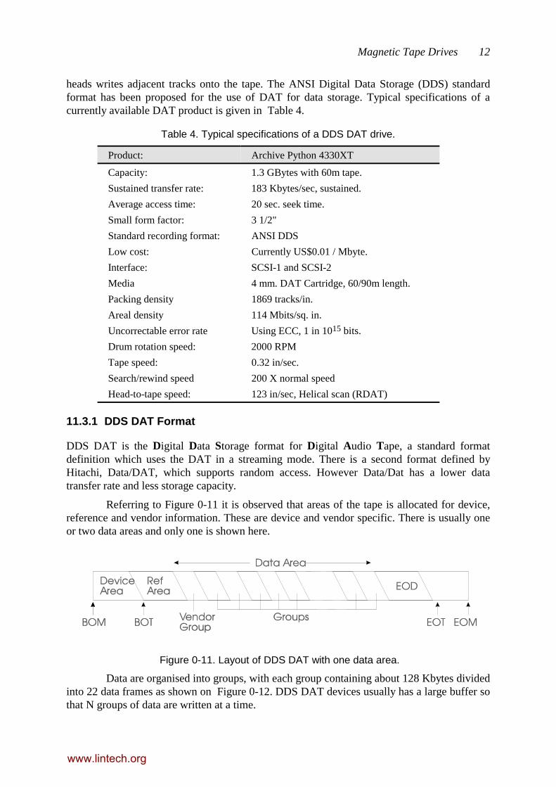
Referring to Figure 0-11 it is observed that areas of the tape is allocated for device,reference and vendor information. These are device and vendor specific. There is usually oneor two data areas and only one is shown here.
Figure 0-11. Layout of DDS DAT with one data area.
Data are organised into groups, with each group containing about 128 Kbytes dividedinto 22 data frames as shown on Figure 0-12. DDS DAT devices usually has a large buffer sothat N groups of data are written at a time.
www.lintech.org

Magnetic Tape Drives 13
Figure 0-12. One DDS DAT data group
Examination of Figure 0-13 shows that each frame is made up of two tracks; track Ais written/read by head A and track B by head B respectively. It can be noted that there is nointer-track gap, and each track overlaps the previous track slightly. At the overlap, signalsfrom one track will interfere with the signal from the other. To eliminate this source of cross-talk interference, the heads are given a small azimuth offset of 20° from the normal. In thisway, the component of noise from the interfering track is strongly attenuated as there is a totaldisorientation of 40° between the write head A and read head B.
Figure 0-13. Alternate azimuth angles.
Figure 0-14 illustrates the format used in each DDS track. The 8/10 code is used andadditional processing like interleaving and Reed-Solomon redundancy is used for errorcorrection. Tone bursts are recorded onto the ATF section. On read-back these signals are fedinto the track following circuits. In operation, when head B is following track B, the pilottones from the two adjacent A tracks are sensed and the amplitude difference is use to moreaccuracy position head B over the track.
Figure 0-14. DDS DAT track format.
www.lintech.org
Magnetic Tape Drives 14
11.3.2 Conclusions
DDS DAT, because of it compactness and high storage capability is rapidly gaining popularityas a backup storage device. Some of the latest products use tape lengths of 90 m. in acartridge. Data compression is built into the drive controller resulting in a device that canstore up to 8 GB per cartridge. If that is still insufficient, there are "juke boxes" withautoloaders that can manage a library of cartridges.
11.4 Additional Reading Guide
John Watkinson, RDAT, Focal Press, 1991
www.lintech.org