Embed Size (px)
Citation preview

Chapter 11 – Interfacing with the Analog World
Digital Systems: Principles and Applications, 11/eRonald J. Tocci, Neal S. Widmer, Gregory L. Moss
Copyright © 2011, 2007, 2004, 2001, 1998 by Pearson Education, Inc.Upper Saddle River, New Jersey 07458 • All rights reserved
• Selected areas covered in this chapter:– Theory of operation and circuit limitations of several
types of digital-to-analog converters (DACs).– Various DAC manufacturer specifications.– Test procedures for troubleshooting DAC circuits.– Advantages/disadvantages of major analog-to-digital
converter (ADC) architectures.– Sample-and-hold circuits in conjunction with ADCs.– Operation of an analog multiplexing system.– Basic concepts of digital signal processing.
Chapter 11 Objectives
Digital Systems: Principles and Applications, 11/eRonald J. Tocci, Neal S. Widmer, Gregory L. Moss
Copyright © 2011, 2007, 2004, 2001, 1998 by Pearson Education, Inc.Upper Saddle River, New Jersey 07458 • All rights reserved
11-1 Interfacing With the Analog World
• A review of the difference between digital and analog quantities:– Digital quantities—values can take on one of two
possible values. • Actual values can be in a specified range, so exact
value is not important.– Analog quantities—values can take on an infinite
number of values, and the exact value is important.
Digital Systems: Principles and Applications, 11/eRonald J. Tocci, Neal S. Widmer, Gregory L. Moss
Copyright © 2011, 2007, 2004, 2001, 1998 by Pearson Education, Inc.Upper Saddle River, New Jersey 07458 • All rights reserved
11-1 Interfacing With the Analog World
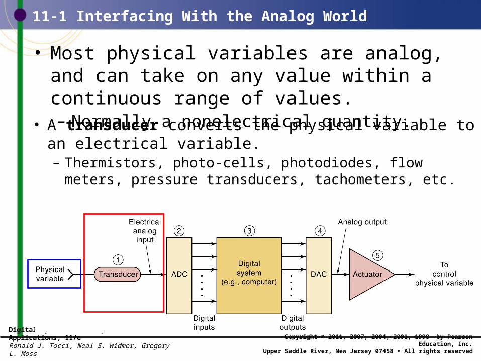
• Most physical variables are analog, and can take on any value within a continuous range of values.– Normally a nonelectrical quantity.
• A transducer converts the physical variable toan electrical variable.– Thermistors, photo-cells, photodiodes, flow meters,
pressure transducers, tachometers, etc.
Digital Systems: Principles and Applications, 11/eRonald J. Tocci, Neal S. Widmer, Gregory L. Moss
Copyright © 2011, 2007, 2004, 2001, 1998 by Pearson Education, Inc.Upper Saddle River, New Jersey 07458 • All rights reserved
11-1 Interfacing With the Analog World
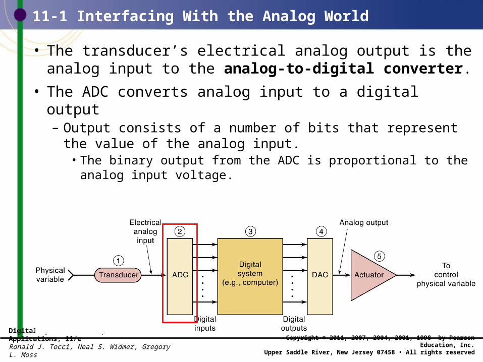
• The transducer’s electrical analog output is the analog input to the analog-to-digital converter.
• The ADC converts analog input to a digital output– Output consists of a number of bits that represent the
value of the analog input.• The binary output from the ADC is proportional to the
analog input voltage.
Digital Systems: Principles and Applications, 11/eRonald J. Tocci, Neal S. Widmer, Gregory L. Moss
Copyright © 2011, 2007, 2004, 2001, 1998 by Pearson Education, Inc.Upper Saddle River, New Jersey 07458 • All rights reserved
11-1 Interfacing With the Analog World
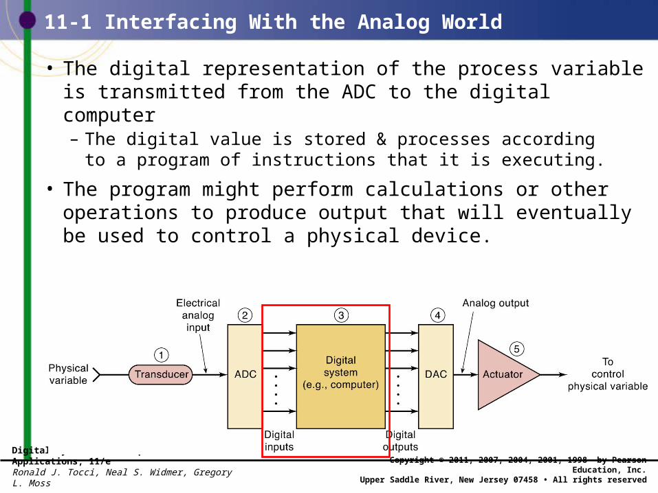
• The digital representation of the process variableis transmitted from the ADC to the digital computer– The digital value is stored & processes according
to a program of instructions that it is executing.
• The program might perform calculations or other operations to produce output that will eventually be used to control a physical device.
Digital Systems: Principles and Applications, 11/eRonald J. Tocci, Neal S. Widmer, Gregory L. Moss
Copyright © 2011, 2007, 2004, 2001, 1998 by Pearson Education, Inc.Upper Saddle River, New Jersey 07458 • All rights reserved
11-1 Interfacing With the Analog World
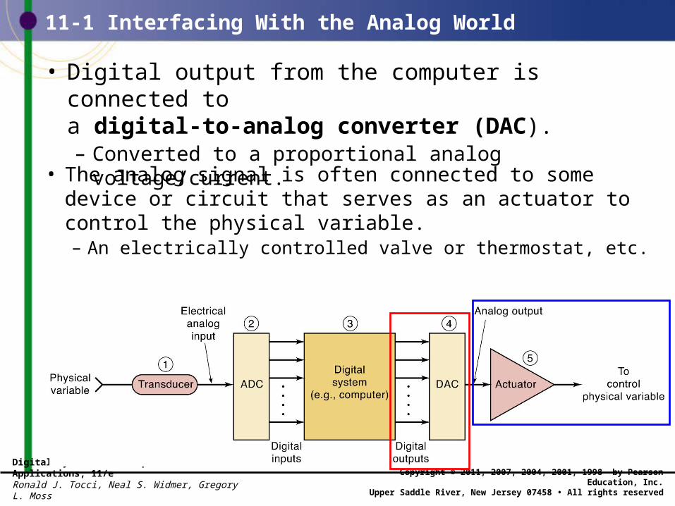
• Digital output from the computer is connected toa digital-to-analog converter (DAC).– Converted to a proportional analog voltage/current.
• The analog signal is often connected to some device or circuit that serves as an actuator to control the physical variable.– An electrically controlled valve or thermostat, etc.
Digital Systems: Principles and Applications, 11/eRonald J. Tocci, Neal S. Widmer, Gregory L. Moss
Copyright © 2011, 2007, 2004, 2001, 1998 by Pearson Education, Inc.Upper Saddle River, New Jersey 07458 • All rights reserved
11-2 Digital to Analog Conversion
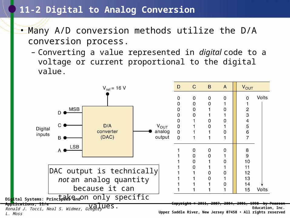
• Many A/D conversion methods utilize the D/A conversion process.– Converting a value represented in digital code to a
voltage or current proportional to the digital value.
DAC output is technically not an analog quantity because it cantake on only specific values.
Digital Systems: Principles and Applications, 11/eRonald J. Tocci, Neal S. Widmer, Gregory L. Moss
Copyright © 2011, 2007, 2004, 2001, 1998 by Pearson Education, Inc.Upper Saddle River, New Jersey 07458 • All rights reserved
11-2 Digital to Analog Conversion
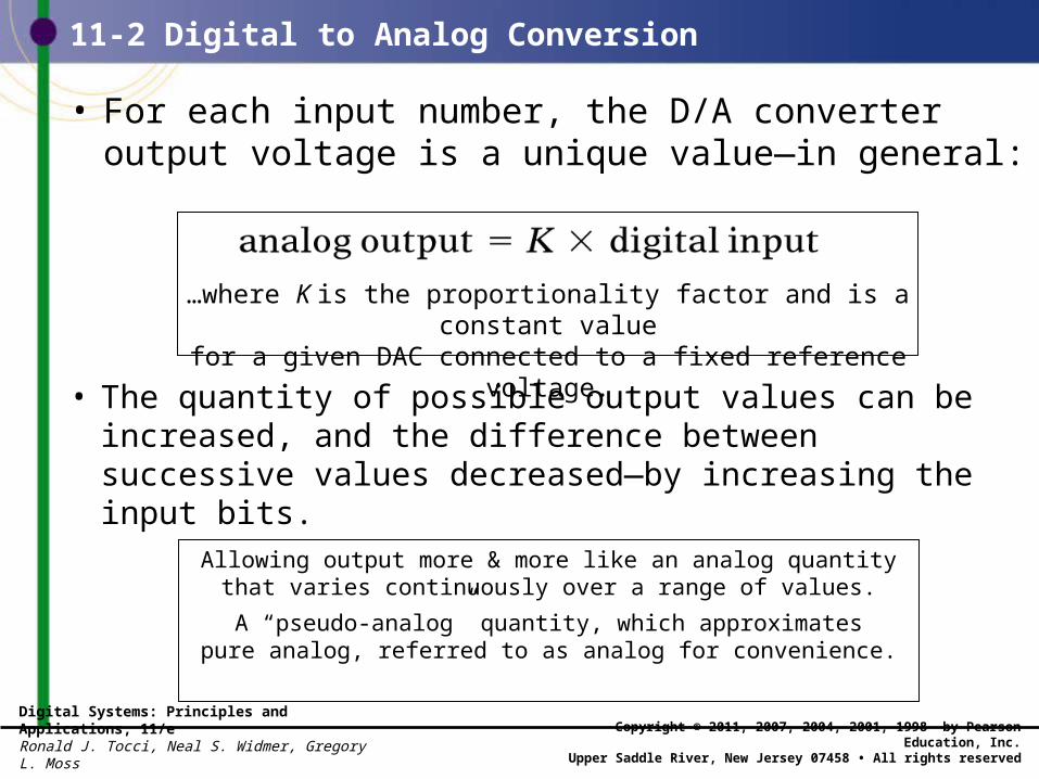
• For each input number, the D/A converter output voltage is a unique value—in general:
• The quantity of possible output values can be increased, and the difference between successive values decreased—by increasing the input bits.
…where K is the proportionality factor and is a constant valuefor a given DAC connected to a fixed reference voltage.
Allowing output more & more like an analog quantitythat varies continuously over a range of values.
A “pseudo-analog” quantity, which approximatespure analog, referred to as analog for convenience.
Digital Systems: Principles and Applications, 11/eRonald J. Tocci, Neal S. Widmer, Gregory L. Moss
Copyright © 2011, 2007, 2004, 2001, 1998 by Pearson Education, Inc.Upper Saddle River, New Jersey 07458 • All rights reserved
11-2 Digital to Analog Conversion
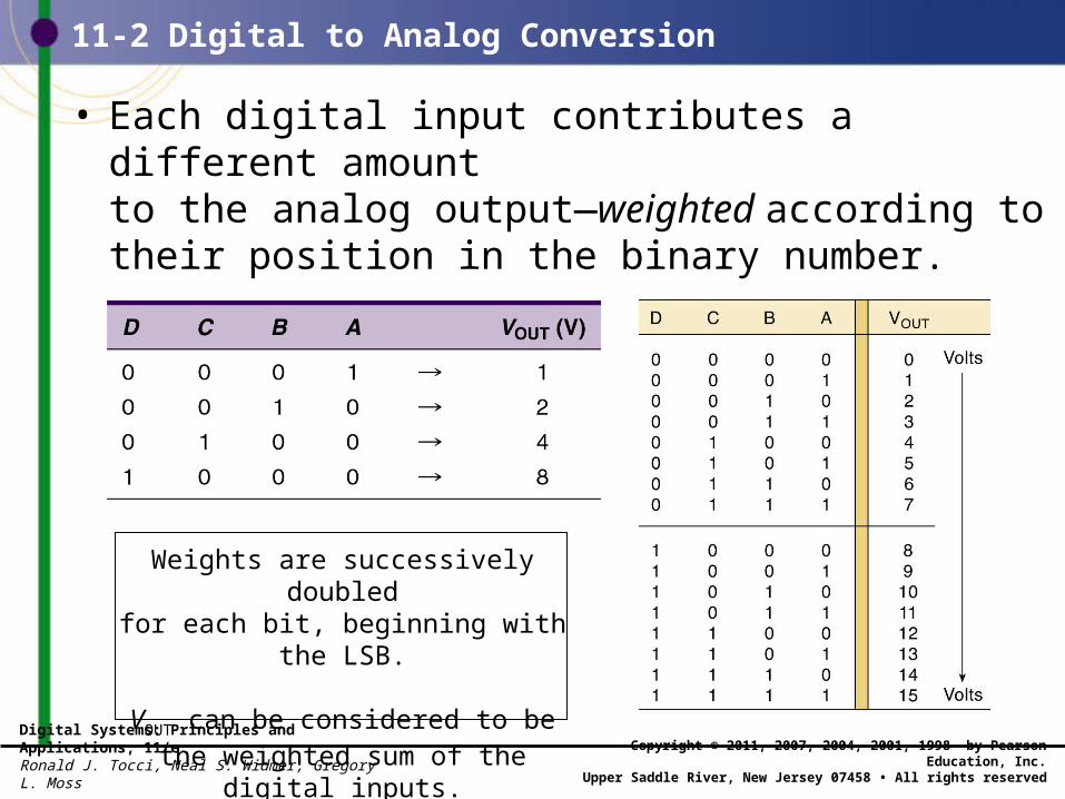
• Each digital input contributes a different amountto the analog output—weighted according to their position in the binary number.
Weights are successively doubledfor each bit, beginning with the LSB.
VOUT can be considered to be the weighted sum of the digital inputs.
Digital Systems: Principles and Applications, 11/eRonald J. Tocci, Neal S. Widmer, Gregory L. Moss
Copyright © 2011, 2007, 2004, 2001, 1998 by Pearson Education, Inc.Upper Saddle River, New Jersey 07458 • All rights reserved
11-2 Digital to Analog Conversion
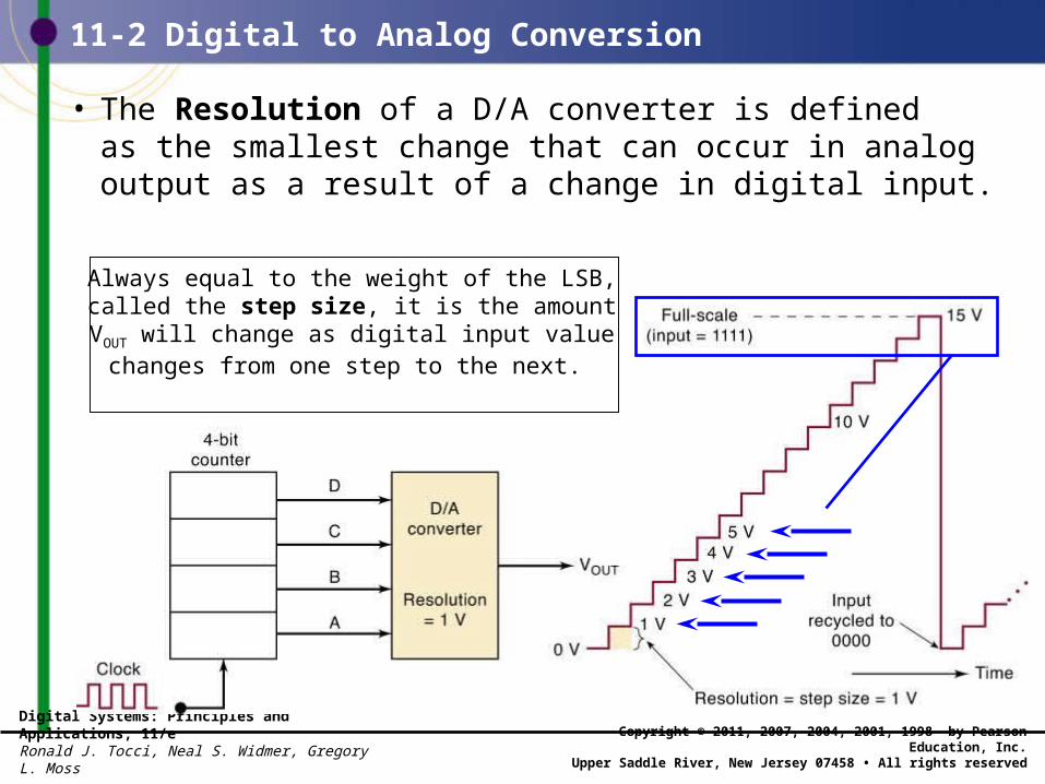
• The Resolution of a D/A converter is definedas the smallest change that can occur in analog output as a result of a change in digital input.
Always equal to the weight of the LSB, called the step size, it is the amount VOUT will change as digital input value changes
from one step to the next.
Digital Systems: Principles and Applications, 11/eRonald J. Tocci, Neal S. Widmer, Gregory L. Moss
Copyright © 2011, 2007, 2004, 2001, 1998 by Pearson Education, Inc.Upper Saddle River, New Jersey 07458 • All rights reserved
11-2 Digital to Analog Conversion
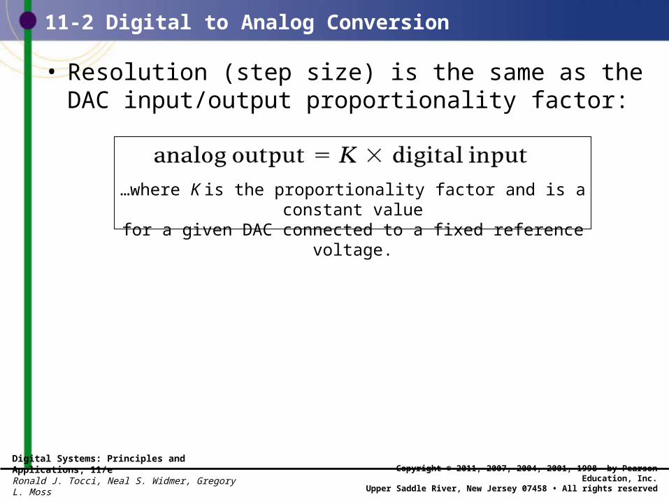
• Resolution (step size) is the same as the DAC input/output proportionality factor:
…where K is the proportionality factor and is a constant valuefor a given DAC connected to a fixed reference voltage.
Digital Systems: Principles and Applications, 11/eRonald J. Tocci, Neal S. Widmer, Gregory L. Moss
Copyright © 2011, 2007, 2004, 2001, 1998 by Pearson Education, Inc.Upper Saddle River, New Jersey 07458 • All rights reserved
11-2 Digital to Analog Conversion
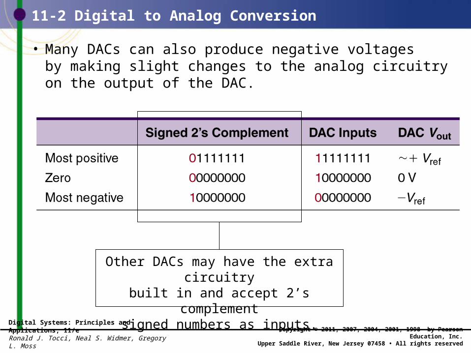
• Many DACs can also produce negative voltagesby making slight changes to the analog circuitryon the output of the DAC.
Other DACs may have the extra circuitrybuilt in and accept 2’s complement
signed numbers as inputs.
Digital Systems: Principles and Applications, 11/eRonald J. Tocci, Neal S. Widmer, Gregory L. Moss
Copyright © 2011, 2007, 2004, 2001, 1998 by Pearson Education, Inc.Upper Saddle River, New Jersey 07458 • All rights reserved
11-3 DAC Circuitry
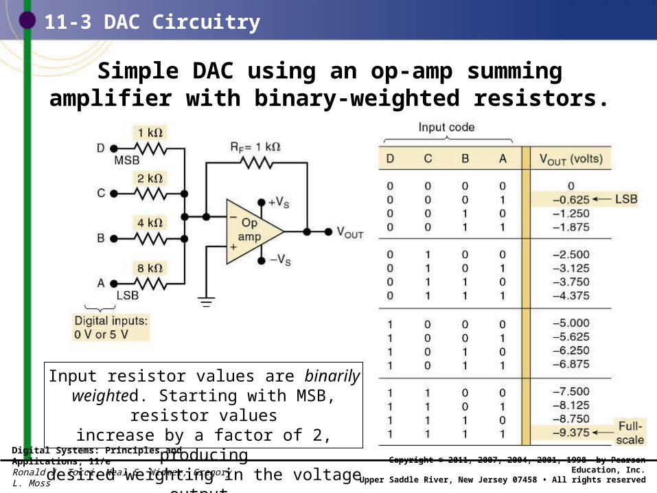
Simple DAC using an op-amp summingamplifier with binary-weighted resistors.
Input resistor values are binarily weighted. Starting with MSB, resistor values
increase by a factor of 2, producingdesired weighting in the voltage output.
Digital Systems: Principles and Applications, 11/eRonald J. Tocci, Neal S. Widmer, Gregory L. Moss
Copyright © 2011, 2007, 2004, 2001, 1998 by Pearson Education, Inc.Upper Saddle River, New Jersey 07458 • All rights reserved
11-3 DAC Circuitry
• How close the circuit comes to producing the ideal values of VOUT depends primarily on two factors.– The precision of the input and feedback resistors.– The precision of the input voltage levels.
• Resistors can be made very accurate by trimming.– Within 0.01 percent of the desired values.
• Digital inputs cannot be taken directly from the outputs of FFs or logic gates because the output logic levels of these vary within given ranges. – It is necessary to add circuitry between each digital
input and its input resistor to the summing amplifier.
Digital Systems: Principles and Applications, 11/eRonald J. Tocci, Neal S. Widmer, Gregory L. Moss
Copyright © 2011, 2007, 2004, 2001, 1998 by Pearson Education, Inc.Upper Saddle River, New Jersey 07458 • All rights reserved
11-3 DAC Circuitry
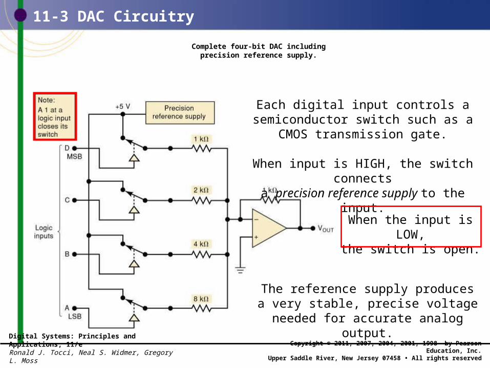
Complete four-bit DAC includingprecision reference supply.
Each digital input controls a semiconductor switch such as a CMOS transmission gate.
When input is HIGH, the switch connectsa precision reference supply to the input.
The reference supply produces a very stable, precise voltage needed for
accurate analog output.
When the input is LOW,the switch is open.
Digital Systems: Principles and Applications, 11/eRonald J. Tocci, Neal S. Widmer, Gregory L. Moss
Copyright © 2011, 2007, 2004, 2001, 1998 by Pearson Education, Inc.Upper Saddle River, New Jersey 07458 • All rights reserved
11-3 DAC Circuitry
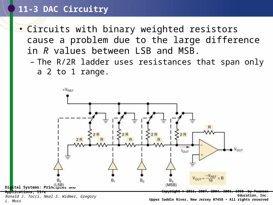
• Circuits with binary weighted resistors cause a problem due to the large difference in R values between LSB and MSB.– The R/2R ladder uses resistances that span only
a 2 to 1 range.
Digital Systems: Principles and Applications, 11/eRonald J. Tocci, Neal S. Widmer, Gregory L. Moss
Copyright © 2011, 2007, 2004, 2001, 1998 by Pearson Education, Inc.Upper Saddle River, New Jersey 07458 • All rights reserved
11-4 DAC Specifications
• Many DACs are available as ICs or self contained packages, and key specifications are:– Resolution; Accuracy.– Offset error; Settling time; Monotonicity.
Digital Systems: Principles and Applications, 11/eRonald J. Tocci, Neal S. Widmer, Gregory L. Moss
Copyright © 2011, 2007, 2004, 2001, 1998 by Pearson Education, Inc.Upper Saddle River, New Jersey 07458 • All rights reserved
11-5 An Integrated Circuit DAC
• The AD7524, a CMOS IC is an eight-bit D/A converter that uses an R/2R ladder network. – This DAC has an eight-bit input that can be latched
internally by Chip Select and WRITE inputs.
• When either control input goes HIGH, the digital input data are latched, and the analog output remains at the level corresponding to thatlatched digital data.
Digital Systems: Principles and Applications, 11/eRonald J. Tocci, Neal S. Widmer, Gregory L. Moss
Copyright © 2011, 2007, 2004, 2001, 1998 by Pearson Education, Inc.Upper Saddle River, New Jersey 07458 • All rights reserved
11-5 An Integrated Circuit DAC
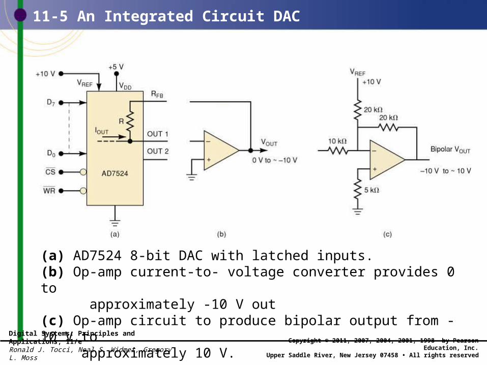
(a) AD7524 8-bit DAC with latched inputs.(b) Op-amp current-to- voltage converter provides 0 to approximately -10 V out(c) Op-amp circuit to produce bipolar output from -10 V to approximately 10 V.
Digital Systems: Principles and Applications, 11/eRonald J. Tocci, Neal S. Widmer, Gregory L. Moss
Copyright © 2011, 2007, 2004, 2001, 1998 by Pearson Education, Inc.Upper Saddle River, New Jersey 07458 • All rights reserved
11-6 DAC Applications
• Used when a digital circuit output must provide an analog voltage or current.– Control—use a digital computer output to adjust motor
speed or furnace temperature.– Automatic testing—computer generated signals to test
analog circuitry.– Signal reconstruction—restoring an analog signal after it
has been converted to digital. – Digital amplitude control—used to reduce the amplitude of
an analog signal.– Serial DACs—with a built-in serial in/parallel out shift
register—many have more than one DAC on the same chip.
Digital Systems: Principles and Applications, 11/eRonald J. Tocci, Neal S. Widmer, Gregory L. Moss
Copyright © 2011, 2007, 2004, 2001, 1998 by Pearson Education, Inc.Upper Saddle River, New Jersey 07458 • All rights reserved
11-7 Troubleshooting DACs
• DACs are both digital and analog.– Logic probes & pulsers can be used on digital inputs.– A meter or an oscilloscope must be used on the
analog output.
• Two ways to test DAC operation: – Static accuracy test—binary input is set to a fixed
value while analog output is checked with a very accurate meter.
– Staircase test—binary input is incremented and output is checked for problems on the “steps”.

Digital Systems: Principles and Applications, 11/eRonald J. Tocci, Neal S. Widmer, Gregory L. Moss
Copyright © 2011, 2007, 2004, 2001, 1998 by Pearson Education, Inc.Upper Saddle River, New Jersey 07458 • All rights reserved
11-8 Analog to digital Conversion
• An analog-to-digital converter takes an analog input voltage and, after a certain amount of time, produces a digital output code that represents the analog input.– Several important types of ADCs utilize a DAC as
part of their circuitry.
• The Op amp comparator ADC– Variations differ in how the control section continually
modifies numbers in the register
Digital Systems: Principles and Applications, 11/eRonald J. Tocci, Neal S. Widmer, Gregory L. Moss
Copyright © 2011, 2007, 2004, 2001, 1998 by Pearson Education, Inc.Upper Saddle River, New Jersey 07458 • All rights reserved
11-8 Analog to digital Conversion
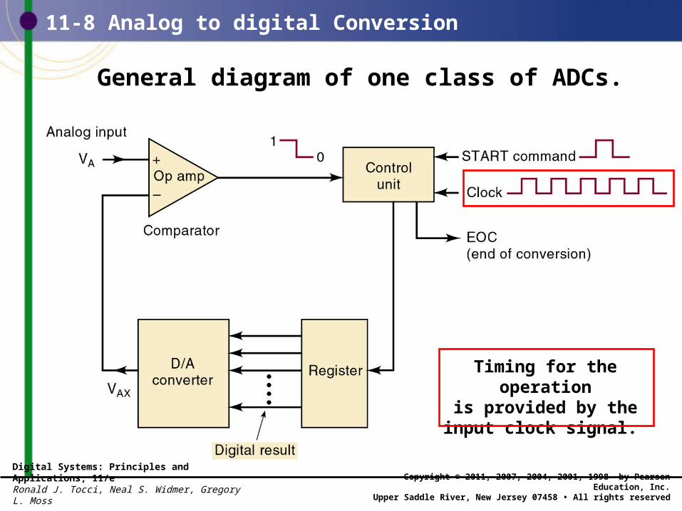
General diagram of one class of ADCs.
Timing for the operationis provided by theinput clock signal.
Digital Systems: Principles and Applications, 11/eRonald J. Tocci, Neal S. Widmer, Gregory L. Moss
Copyright © 2011, 2007, 2004, 2001, 1998 by Pearson Education, Inc.Upper Saddle River, New Jersey 07458 • All rights reserved
11-8 Analog to digital Conversion
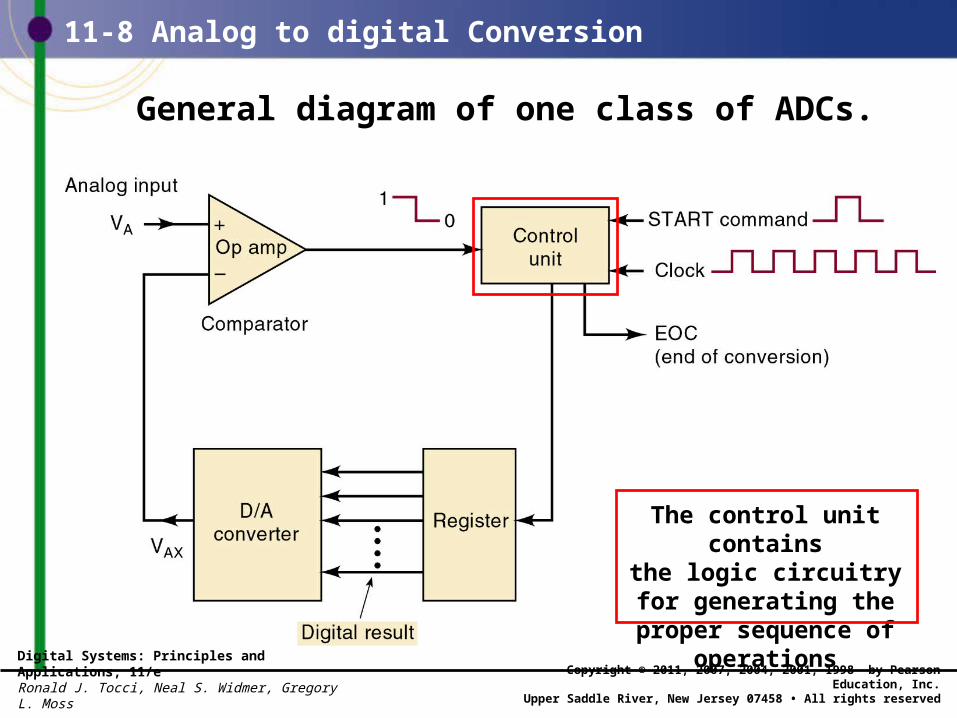
General diagram of one class of ADCs.
The control unit containsthe logic circuitry for generating the proper
sequence of operations
Digital Systems: Principles and Applications, 11/eRonald J. Tocci, Neal S. Widmer, Gregory L. Moss
Copyright © 2011, 2007, 2004, 2001, 1998 by Pearson Education, Inc.Upper Saddle River, New Jersey 07458 • All rights reserved
11-8 Analog to digital Conversion
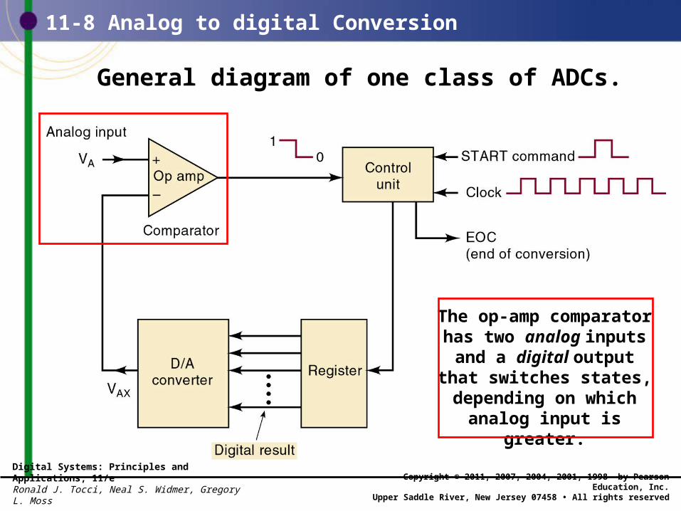
General diagram of one class of ADCs.
The op-amp comparator has two analog inputs
and a digital outputthat switches states, depending on which
analog input is greater.
Digital Systems: Principles and Applications, 11/eRonald J. Tocci, Neal S. Widmer, Gregory L. Moss
Copyright © 2011, 2007, 2004, 2001, 1998 by Pearson Education, Inc.Upper Saddle River, New Jersey 07458 • All rights reserved
11-8 Analog to digital Conversion
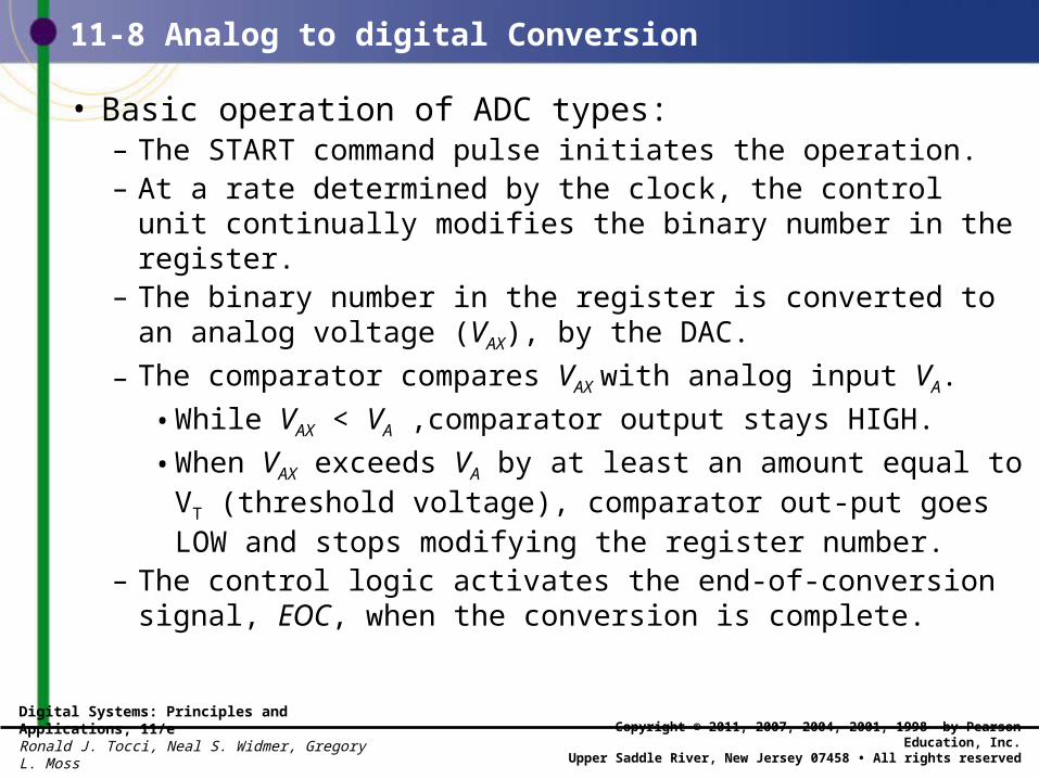
• Basic operation of ADC types:– The START command pulse initiates the operation.– At a rate determined by the clock, the control unit
continually modifies the binary number in the register.– The binary number in the register is converted to an analog
voltage (VAX), by the DAC.
– The comparator compares VAX with analog input VA.
• While VAX < VA ,comparator output stays HIGH.
• When VAX exceeds VA by at least an amount equal to VT (threshold voltage), comparator out-put goes LOW and stops modifying the register number.
– The control logic activates the end-of-conversion signal, EOC, when the conversion is complete.
Digital Systems: Principles and Applications, 11/eRonald J. Tocci, Neal S. Widmer, Gregory L. Moss
Copyright © 2011, 2007, 2004, 2001, 1998 by Pearson Education, Inc.Upper Saddle River, New Jersey 07458 • All rights reserved
• One of the simplest versions of the general ADC uses a binary counter as the register and allows the clock to increment the counter one step at a time until VAX > VA.
11-8 Analog to digital Conversion
– Called a digital-ramp ADC because the waveformat VAX is a step-by-step ramp.

Digital Systems: Principles and Applications, 11/eRonald J. Tocci, Neal S. Widmer, Gregory L. Moss
Copyright © 2011, 2007, 2004, 2001, 1998 by Pearson Education, Inc.Upper Saddle River, New Jersey 07458 • All rights reserved
11-9 Digital Ramp ADCDigital-ramp ADC
Digital Systems: Principles and Applications, 11/eRonald J. Tocci, Neal S. Widmer, Gregory L. Moss
Copyright © 2011, 2007, 2004, 2001, 1998 by Pearson Education, Inc.Upper Saddle River, New Jersey 07458 • All rights reserved
11-9 Digital Ramp ADC
• A/D resolution and accuracy.– Measurement error is unavoidable.– Reducing the step size can reduce but not eliminate
potential error—called quantization error.
Digital Systems: Principles and Applications, 11/eRonald J. Tocci, Neal S. Widmer, Gregory L. Moss
Copyright © 2011, 2007, 2004, 2001, 1998 by Pearson Education, Inc.Upper Saddle River, New Jersey 07458 • All rights reserved
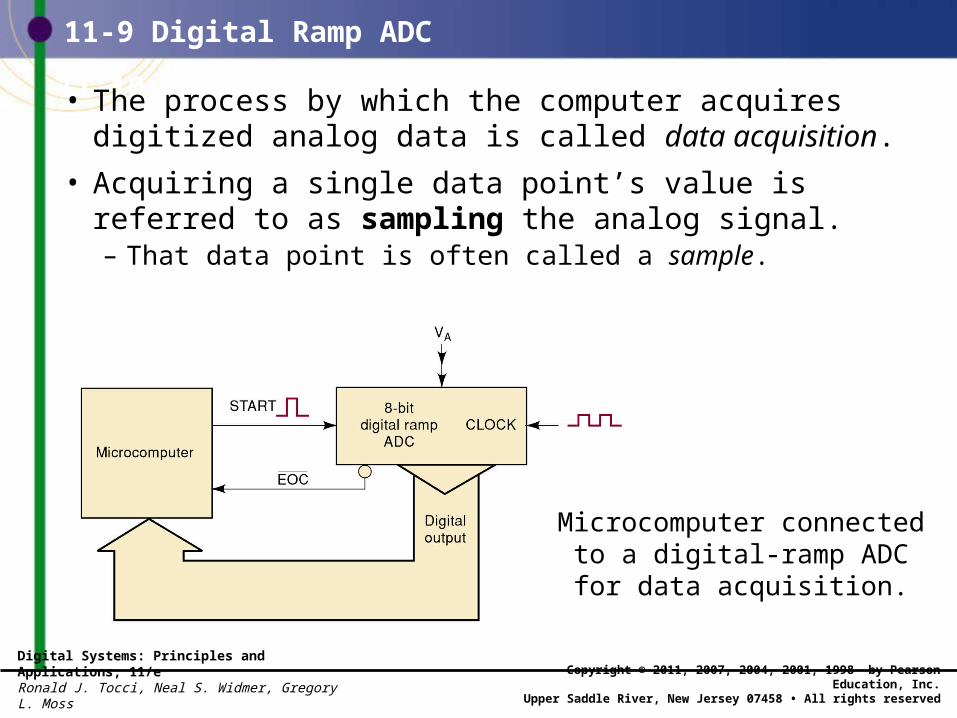
11-10 Data Acquisition• The process by which the computer acquires digitized analog data is called data acquisition.
• Acquiring a single data point’s value isreferred to as sampling the analog signal.– That data point is often called a sample.
11-9 Digital Ramp ADC
Microcomputer connectedto a digital-ramp ADCfor data acquisition.

Digital Systems: Principles and Applications, 11/eRonald J. Tocci, Neal S. Widmer, Gregory L. Moss
Copyright © 2011, 2007, 2004, 2001, 1998 by Pearson Education, Inc.Upper Saddle River, New Jersey 07458 • All rights reserved
11-10 Data AcquisitionThe waveforms illustrate how the computer acquires digital version of the analog signal (VA ).
11-9 Digital Ramp ADC
Digital Systems: Principles and Applications, 11/eRonald J. Tocci, Neal S. Widmer, Gregory L. Moss
Copyright © 2011, 2007, 2004, 2001, 1998 by Pearson Education, Inc.Upper Saddle River, New Jersey 07458 • All rights reserved
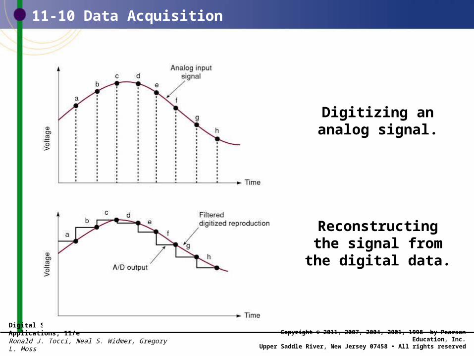
11-10 Data Acquisition
Digitizing ananalog signal.
Reconstructingthe signal fromthe digital data.
Digital Systems: Principles and Applications, 11/eRonald J. Tocci, Neal S. Widmer, Gregory L. Moss
Copyright © 2011, 2007, 2004, 2001, 1998 by Pearson Education, Inc.Upper Saddle River, New Jersey 07458 • All rights reserved
11-10 Data Acquisition
• The goal in signal reconstruction is to make the reconstruction nearly identical to the original analog signal.
• To avoid loss of information, the incoming signal must be sampled at a rate greater than two times the frequency component in the incoming signal.– Proven by a man named Harry Nyquist.
• The frequency at which samples are taken is referred to as the sampling frequency (FS).
Digital Systems: Principles and Applications, 11/eRonald J. Tocci, Neal S. Widmer, Gregory L. Moss
Copyright © 2011, 2007, 2004, 2001, 1998 by Pearson Education, Inc.Upper Saddle River, New Jersey 07458 • All rights reserved
11-10 Data Acquisition
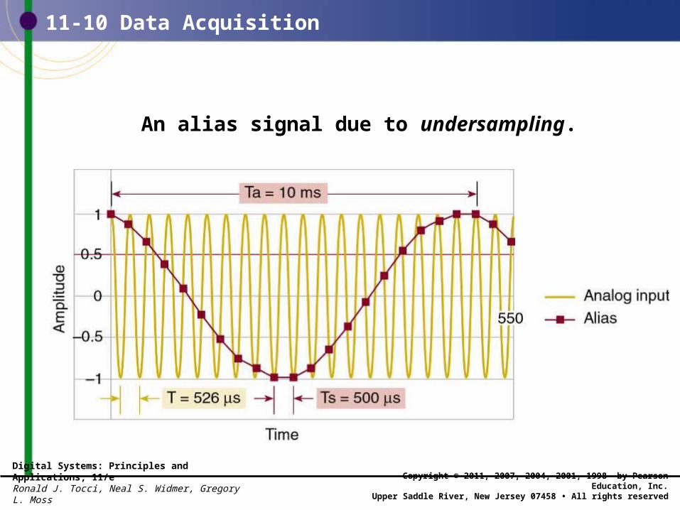
• Consider sampling a 10-kHz frequency, at 20,000 samples/sec. – If, for example a 12-kHz tone were present in the input
signal, a phenomenon called aliasing would occur.– A signal alias is produced by sampling at less than
the minimum rate—in this case, 24,000 samples/sec.• The alias frequency is always the difference between
any integer multiple of the sampling frequency andthe incoming frequency being digitized.
Digital Systems: Principles and Applications, 11/eRonald J. Tocci, Neal S. Widmer, Gregory L. Moss
Copyright © 2011, 2007, 2004, 2001, 1998 by Pearson Education, Inc.Upper Saddle River, New Jersey 07458 • All rights reserved
11-10 Data Acquisition
An alias signal due to undersampling.
Digital Systems: Principles and Applications, 11/eRonald J. Tocci, Neal S. Widmer, Gregory L. Moss
Copyright © 2011, 2007, 2004, 2001, 1998 by Pearson Education, Inc.Upper Saddle River, New Jersey 07458 • All rights reserved
11-11 Successive Approximation ADC
• The successive-approximation converter is one of the most widely used types of ADC. – It has more complex circuitry than the digital-ramp
ADC but a much shorter conversion time. • A fixed value of conversion time not dependent
on the value of the analog input.
Digital Systems: Principles and Applications, 11/eRonald J. Tocci, Neal S. Widmer, Gregory L. Moss
Copyright © 2011, 2007, 2004, 2001, 1998 by Pearson Education, Inc.Upper Saddle River, New Jersey 07458 • All rights reserved
11-11 Successive Approximation ADC
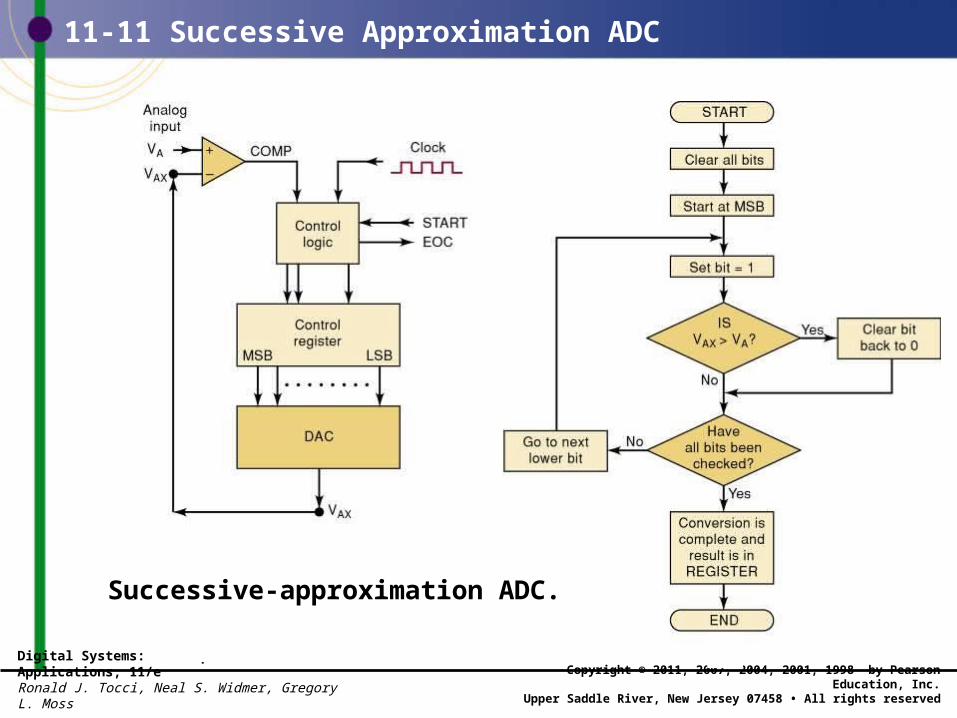
Successive-approximation ADC.
Digital Systems: Principles and Applications, 11/eRonald J. Tocci, Neal S. Widmer, Gregory L. Moss
Copyright © 2011, 2007, 2004, 2001, 1998 by Pearson Education, Inc.Upper Saddle River, New Jersey 07458 • All rights reserved
11-11 Successive Approximation ADC
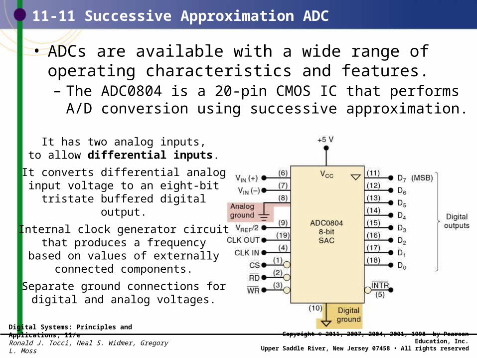
• ADCs are available with a wide range of operating characteristics and features. – The ADC0804 is a 20-pin CMOS IC that performs
A/D conversion using successive approximation.
It has two analog inputs,to allow differential inputs.
It converts differential analoginput voltage to an eight-bit
tristate buffered digital output.
Internal clock generator circuitthat produces a frequency
based on values of externally connected components.
Separate ground connections for digital and analog voltages.
Digital Systems: Principles and Applications, 11/eRonald J. Tocci, Neal S. Widmer, Gregory L. Moss
Copyright © 2011, 2007, 2004, 2001, 1998 by Pearson Education, Inc.Upper Saddle River, New Jersey 07458 • All rights reserved
11-12 Flash ADCs
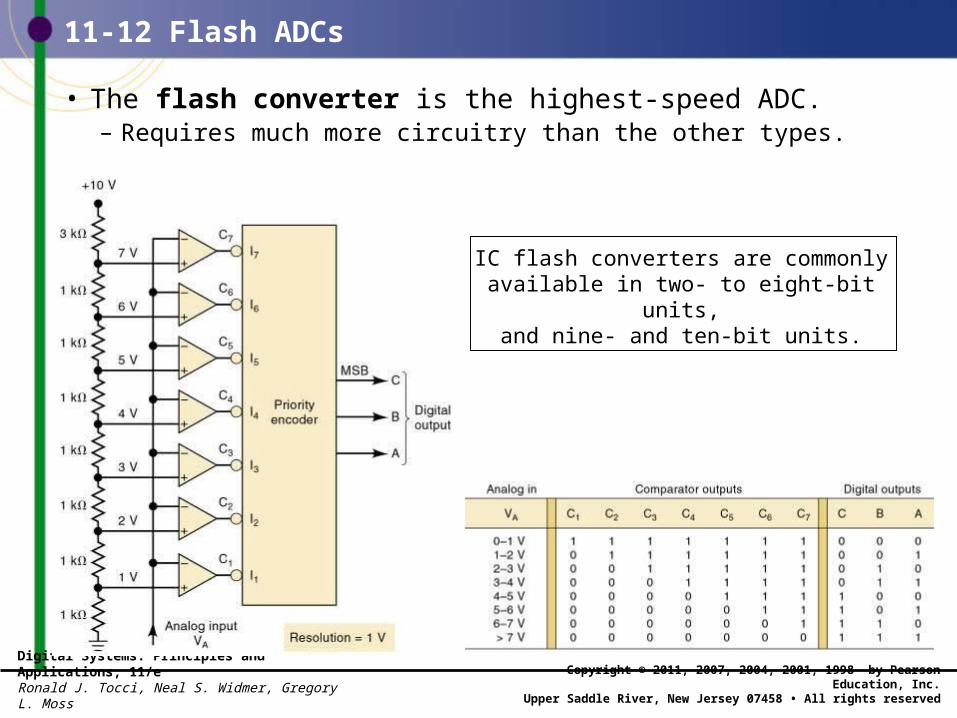
• The flash converter is the highest-speed ADC.– Requires much more circuitry than the other types.
IC flash converters are commonly available in two- to eight-bit units,
and nine- and ten-bit units.
Digital Systems: Principles and Applications, 11/eRonald J. Tocci, Neal S. Widmer, Gregory L. Moss
Copyright © 2011, 2007, 2004, 2001, 1998 by Pearson Education, Inc.Upper Saddle River, New Jersey 07458 • All rights reserved
11-12 Flash ADCs
• Flash converters use no clock signal because no timing or sequencing is required. – The conversion takes place continuously.
• When analog input value changes, comparator outputs change—causing encoder output change. – Conversion time depends only on the propagation
delays of the comparators and encoder logic.
• Flash converters can be very expensive and tend to have relatively low resolutions and high power consumption.
Digital Systems: Principles and Applications, 11/eRonald J. Tocci, Neal S. Widmer, Gregory L. Moss
Copyright © 2011, 2007, 2004, 2001, 1998 by Pearson Education, Inc.Upper Saddle River, New Jersey 07458 • All rights reserved
11-13 Other A/D Conversion Methods
• There are many other methods of A/D conversion.– The dual-slope converter has one of the slowest
conversion times (typically 10 to 100 ms).• Relatively low cost—no precision components.
– The voltage-to-frequency ADC is simpler thanother ADCs because it does not use a DAC.
• A linear voltage-controlled oscillator (VCO) producesan output frequency proportional to input voltage.
– A sigma/delta modulation converter is an over-sampling device.
• It effectively samples the analog information moreoften than the minimum sample rate.
– A pipelined ADC has two or more subranging stages.• Each with an n-bit ADC along with an n-bit DAC.
Digital Systems: Principles and Applications, 11/eRonald J. Tocci, Neal S. Widmer, Gregory L. Moss
Copyright © 2011, 2007, 2004, 2001, 1998 by Pearson Education, Inc.Upper Saddle River, New Jersey 07458 • All rights reserved
11-14 Typical ADC Architecture for Applications
• Most ADC applications fall into one of four areas: – Precision industrial measurement.– Voice/audio.– Data acquisition.– High speed.

Digital Systems: Principles and Applications, 11/eRonald J. Tocci, Neal S. Widmer, Gregory L. Moss
Copyright © 2011, 2007, 2004, 2001, 1998 by Pearson Education, Inc.Upper Saddle River, New Jersey 07458 • All rights reserved
11-15 Sample and Hold Circuits
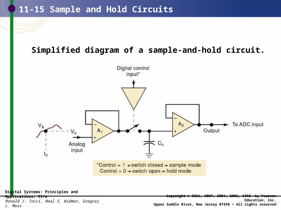
• Analog voltage connected directly to an ADC input conversion can be adversely affected if analog voltage is changing during the conversion time.
• Stability of conversion can be improved by usinga sample-and-hold (S/H) circuit.– To hold the analog voltage constant while the A/D
conversion is taking place.
• In a computer-controlled data acquisition system the sample-and-hold switch would be controlled by a digital signal from the computer. – The amount of time the switch would have to remain
closed is called the acquisition time
Digital Systems: Principles and Applications, 11/eRonald J. Tocci, Neal S. Widmer, Gregory L. Moss
Copyright © 2011, 2007, 2004, 2001, 1998 by Pearson Education, Inc.Upper Saddle River, New Jersey 07458 • All rights reserved
11-15 Sample and Hold Circuits
Simplified diagram of a sample-and-hold circuit.
Digital Systems: Principles and Applications, 11/eRonald J. Tocci, Neal S. Widmer, Gregory L. Moss
Copyright © 2011, 2007, 2004, 2001, 1998 by Pearson Education, Inc.Upper Saddle River, New Jersey 07458 • All rights reserved
11-16 Multiplexing
• When analog inputs from several sources are to be converted, a multiplexing technique can be used so that one ADC may be time-shared.
Digital Systems: Principles and Applications, 11/eRonald J. Tocci, Neal S. Widmer, Gregory L. Moss
Copyright © 2011, 2007, 2004, 2001, 1998 by Pearson Education, Inc.Upper Saddle River, New Jersey 07458 • All rights reserved
11-16 Multiplexing
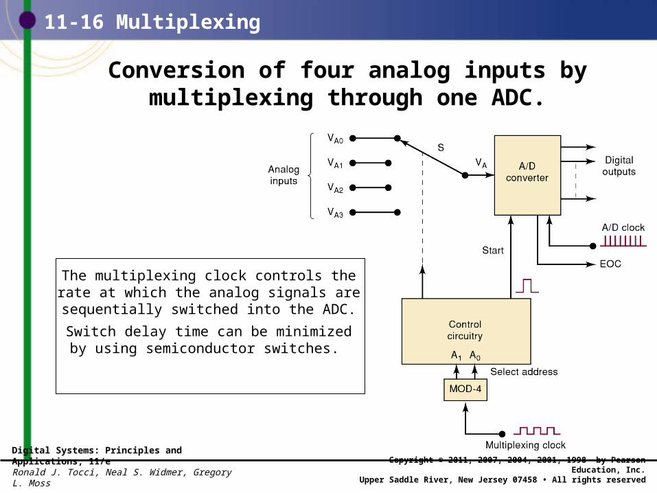
Conversion of four analog inputs bymultiplexing through one ADC.
The multiplexing clock controls therate at which the analog signals are sequentially switched into the ADC.
Switch delay time can be minimizedby using semiconductor switches.
Digital Systems: Principles and Applications, 11/eRonald J. Tocci, Neal S. Widmer, Gregory L. Moss
Copyright © 2011, 2007, 2004, 2001, 1998 by Pearson Education, Inc.Upper Saddle River, New Jersey 07458 • All rights reserved
11-16 Multiplexing
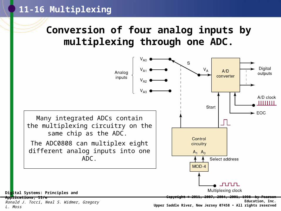
Conversion of four analog inputs bymultiplexing through one ADC.
Many integrated ADCs containthe multiplexing circuitry on the
same chip as the ADC.
The ADC0808 can multiplex eight different analog inputs into one ADC.
Digital Systems: Principles and Applications, 11/eRonald J. Tocci, Neal S. Widmer, Gregory L. Moss
Copyright © 2011, 2007, 2004, 2001, 1998 by Pearson Education, Inc.Upper Saddle River, New Jersey 07458 • All rights reserved
11-17 Digital Signal Processing (DSP)
• A digital signal processor (DSP) is a very specialized form of microprocessor, optimizedto perform repetitive calculations on streams of digitized data. – Digitized data are usually fed to the DSP from an
A/D converter.
• A major application for DSP is filtering/conditioning of analog signals.– The advantage of DSP over resistors and capacitors
is the flexibility of being able to change the critical frequency without switching any components.
Digital Systems: Principles and Applications, 11/eRonald J. Tocci, Neal S. Widmer, Gregory L. Moss
Copyright © 2011, 2007, 2004, 2001, 1998 by Pearson Education, Inc.Upper Saddle River, New Jersey 07458 • All rights reserved
11-17 Digital Signal Processing (DSP)
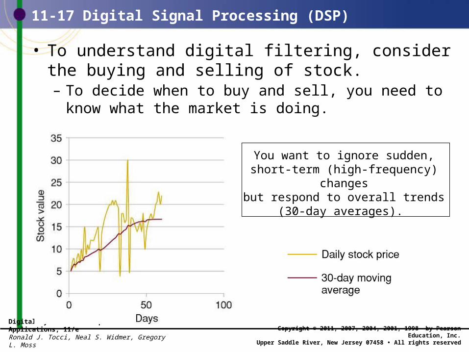
• To understand digital filtering, consider the buying and selling of stock. – To decide when to buy and sell, you need to know
what the market is doing.
You want to ignore sudden, short-term (high-frequency) changesbut respond to overall trends
(30-day averages).
Digital Systems: Principles and Applications, 11/eRonald J. Tocci, Neal S. Widmer, Gregory L. Moss
Copyright © 2011, 2007, 2004, 2001, 1998 by Pearson Education, Inc.Upper Saddle River, New Jersey 07458 • All rights reserved
11-17 Digital Signal Processing (DSP)
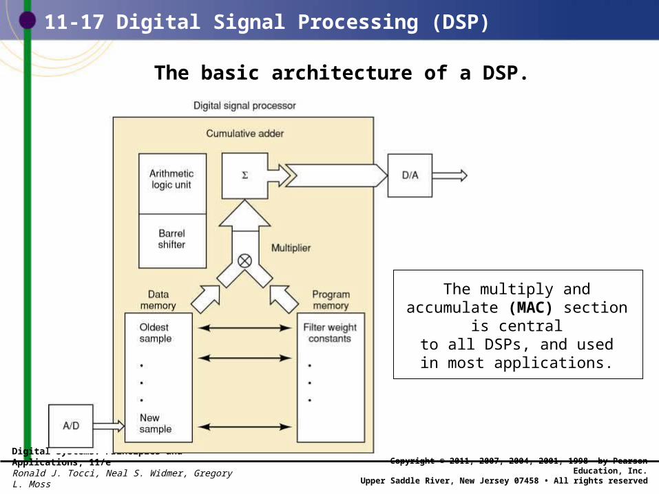
The basic architecture of a DSP.
The multiply and accumulate (MAC) section is centralto all DSPs, and usedin most applications.
Digital Systems: Principles and Applications, 11/eRonald J. Tocci, Neal S. Widmer, Gregory L. Moss
Copyright © 2011, 2007, 2004, 2001, 1998 by Pearson Education, Inc.Upper Saddle River, New Jersey 07458 • All rights reserved
11-17 Digital Signal Processing (DSP)
• Digital filtering process—weighted average.– Read the newest sample.– Replace the oldest sample with the new one.– Multiply each of the 256 samples by corresponding
weight constant.– Add all products.– Output the resulting sum of products to the D/A.
Digital Systems: Principles and Applications, 11/eRonald J. Tocci, Neal S. Widmer, Gregory L. Moss
Copyright © 2011, 2007, 2004, 2001, 1998 by Pearson Education, Inc.Upper Saddle River, New Jersey 07458 • All rights reserved
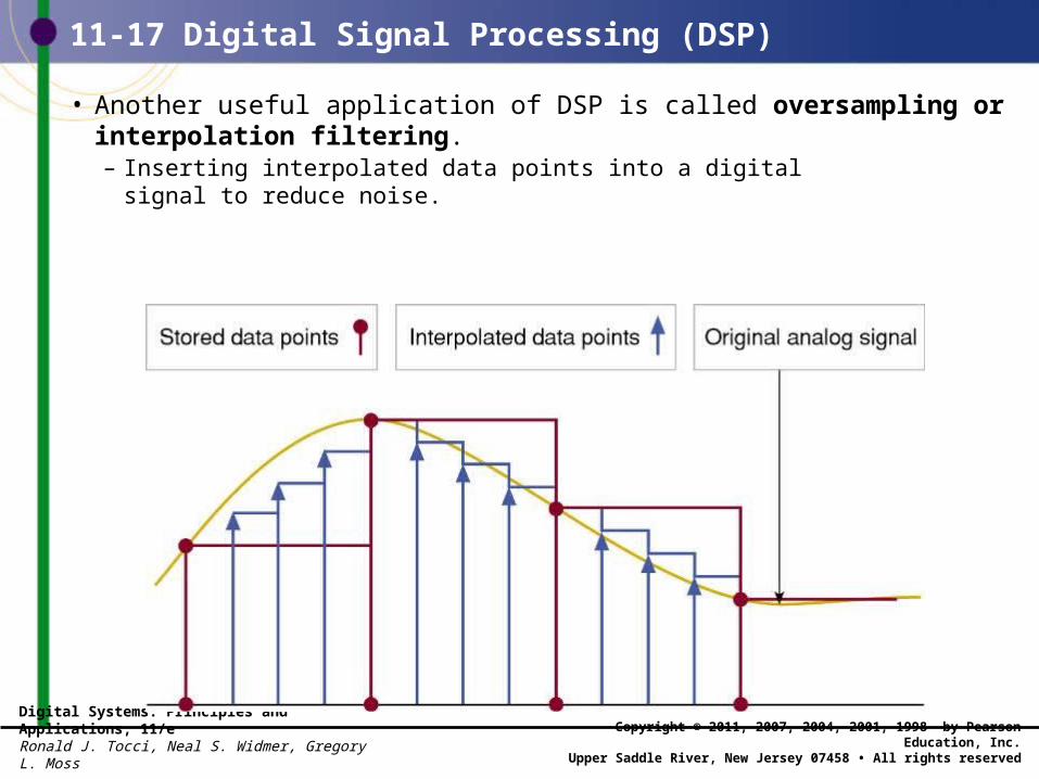
11-17 Digital Signal Processing (DSP)
• Another useful application of DSP is called oversampling or interpolation filtering.– Inserting interpolated data points into a digital
signal to reduce noise.
Digital Systems: Principles and Applications, 11/eRonald J. Tocci, Neal S. Widmer, Gregory L. Moss
Copyright © 2011, 2007, 2004, 2001, 1998 by Pearson Education, Inc.Upper Saddle River, New Jersey 07458 • All rights reserved
11-17 Digital Signal Processing (DSP)
• DSP applications:– Filters in CD players to minimize quantization noise.– Echo canceling in telephone systems.– PC modems.– Musical instrument special effects.– Digital television.– Voice recognition.
Digital Systems: Principles and Applications, 11/eRonald J. Tocci, Neal S. Widmer, Gregory L. Moss
Copyright © 2011, 2007, 2004, 2001, 1998 by Pearson Education, Inc.Upper Saddle River, New Jersey 07458 • All rights reserved
11-18 Applications of Analog Interfacing
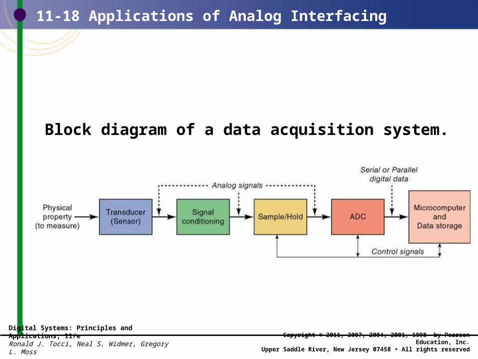
Block diagram of a data acquisition system.
Digital Systems: Principles and Applications, 11/eRonald J. Tocci, Neal S. Widmer, Gregory L. Moss
Copyright © 2011, 2007, 2004, 2001, 1998 by Pearson Education, Inc.Upper Saddle River, New Jersey 07458 • All rights reserved
11-18 Applications of Analog Interfacing
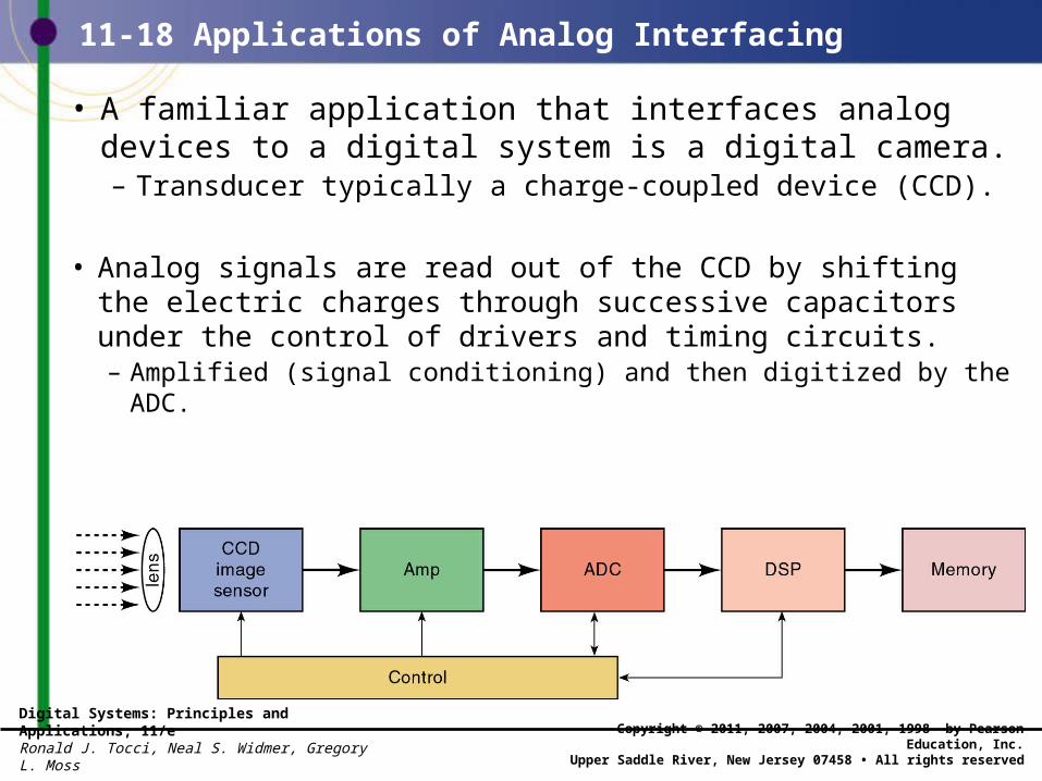
• A familiar application that interfaces analog devices to a digital system is a digital camera.– Transducer typically a charge-coupled device (CCD).
• Analog signals are read out of the CCD by shifting the electric charges through successive capacitors under the control of drivers and timing circuits. – Amplified (signal conditioning) and then digitized by the ADC.
Digital Systems: Principles and Applications, 11/eRonald J. Tocci, Neal S. Widmer, Gregory L. Moss
Copyright © 2011, 2007, 2004, 2001, 1998 by Pearson Education, Inc.Upper Saddle River, New Jersey 07458 • All rights reserved
11-18 Applications of Analog Interfacing
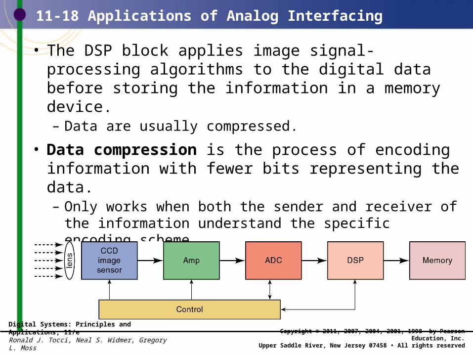
• The DSP block applies image signal-processing algorithms to the digital data before storing the information in a memory device. – Data are usually compressed.
• Data compression is the process of encoding information with fewer bits representing the data. – Only works when both the sender and receiver of the
information understand the specific encoding scheme.
END