Embed Size (px)
Citation preview
Chapter 11
Digital Radiography
Digital Radiography• Digital Radiology Department
– Intrinsically digital: CT, MRI– Already digitalized: Ultrasound, PET, – DR: last image modality to be totally digital
• Screen–film radiography– High image quality: low motivation for digitalization
• Digital Radiography– Requires lots of space for digital media storage
• 2k×2k×8bit=4MB, 4k×4k×12bit=32MB– High bandwidth network– Costly high luminance & high resolution monitor
• 2k×2.5k
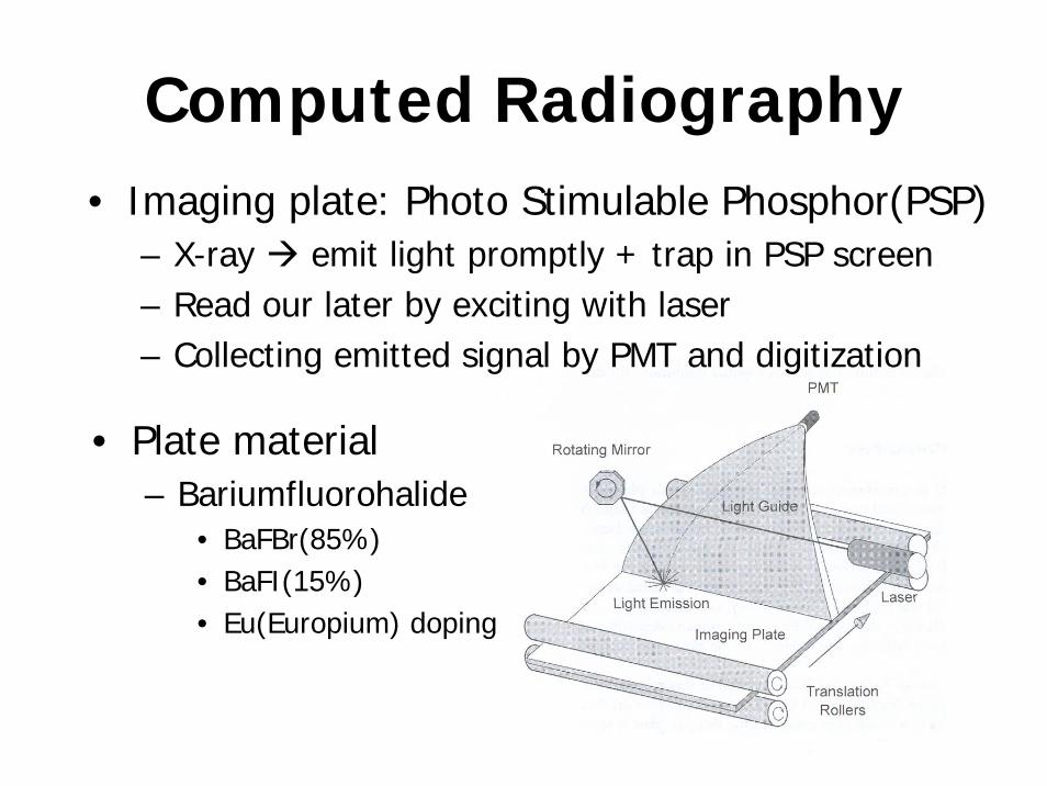
Computed Radiography• Imaging plate: Photo Stimulable Phosphor(PSP)
– X-ray emit light promptly + trap in PSP screen– Read our later by exciting with laser– Collecting emitted signal by PMT and digitization
• Plate material– Bariumfluorohalide
• BaFBr(85%)• BaFI(15%)• Eu(Europium) doping
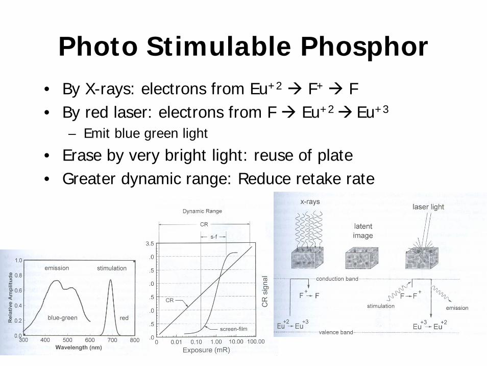
Photo Stimulable Phosphor• By X-rays: electrons from Eu+2 F+ F• By red laser: electrons from F Eu+2 Eu+3
– Emit blue green light
• Erase by very bright light: reuse of plate• Greater dynamic range: Reduce retake rate
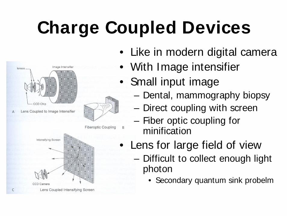
Charge Coupled Devices• Like in modern digital camera• With Image intensifier• Small input image
– Dental, mammography biopsy– Direct coupling with screen– Fiber optic coupling for
minification• Lens for large field of view
– Difficult to collect enough light photon
• Secondary quantum sink probelm
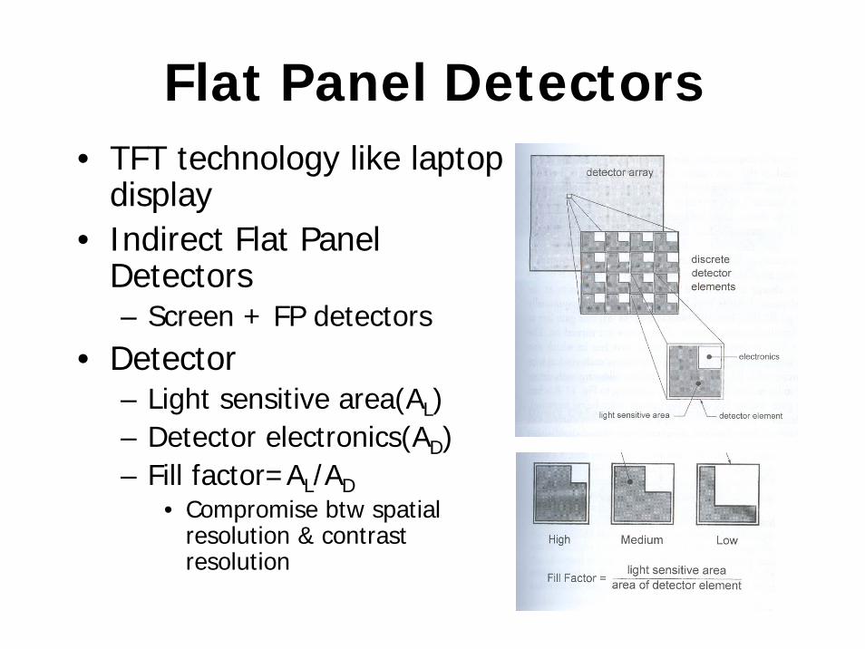
Flat Panel Detectors• TFT technology like laptop
display• Indirect Flat Panel
Detectors– Screen + FP detectors
• Detector– Light sensitive area(AL)– Detector electronics(AD)– Fill factor=AL/AD
• Compromise btw spatial resolution & contrast resolution
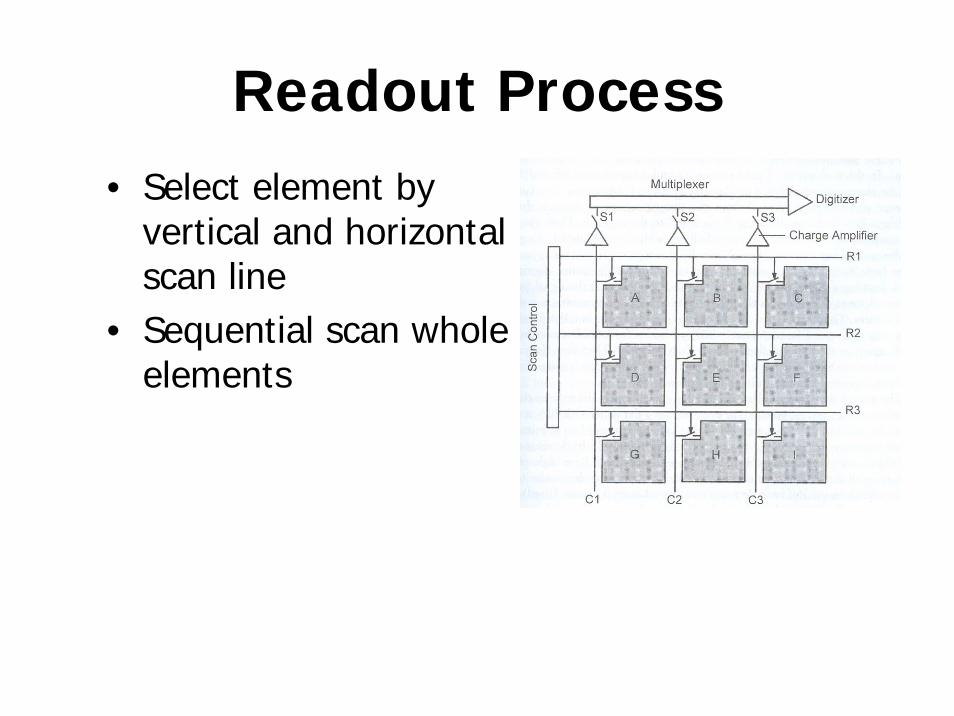
Readout Process• Select element by
vertical and horizontal scan line
• Sequential scan whole elements
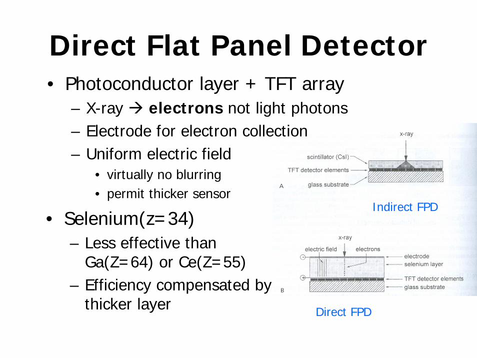
Direct Flat Panel Detector• Photoconductor layer + TFT array
– X-ray electrons not light photons– Electrode for electron collection– Uniform electric field
• virtually no blurring• permit thicker sensor
• Selenium(z=34)– Less effective than
Ga(Z=64) or Ce(Z=55)– Efficiency compensated by
thicker layer
Indirect FPD
Direct FPD
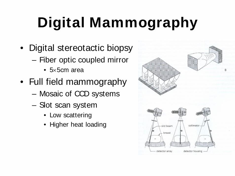
Digital Mammography
• Digital stereotactic biopsy– Fiber optic coupled mirror
• 5×5cm area
• Full field mammography– Mosaic of CCD systems– Slot scan system
• Low scattering• Higher heat loading
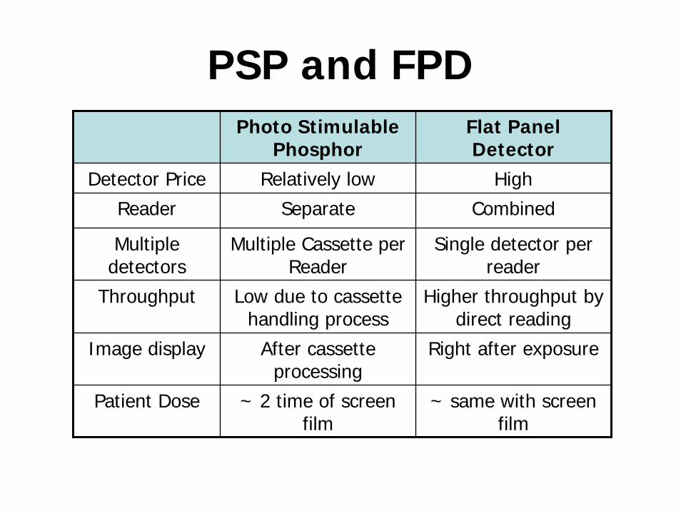
PSP and FPDPhoto Stimulable
PhosphorFlat Panel Detector
Detector Price Relatively low High
Reader Separate Combined
Multiple detectors
Multiple Cassette per Reader
Single detector per reader
Throughput Low due to cassette handling process
Higher throughput by direct reading
Image display After cassette processing
Right after exposure
Patient Dose ~ 2 time of screen film
~ same with screen film
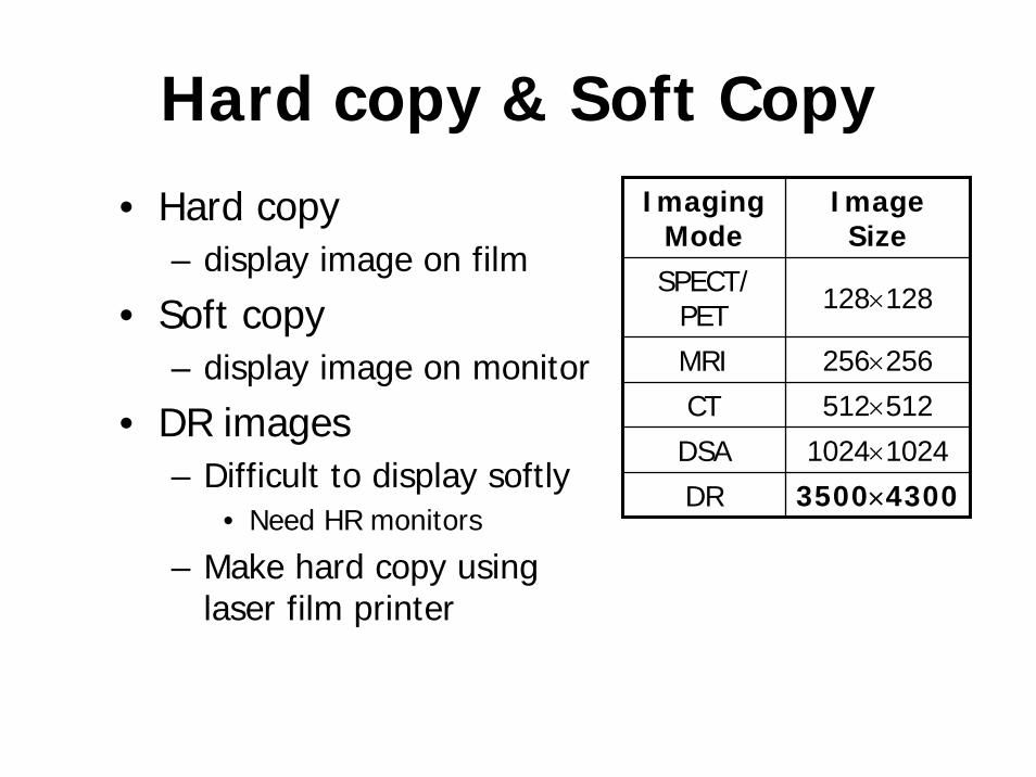
Hard copy & Soft Copy• Hard copy
– display image on film
• Soft copy– display image on monitor
• DR images– Difficult to display softly
• Need HR monitors
– Make hard copy using laser film printer
Imaging Mode
Image Size
SPECT/ PET 128×128
MRI 256×256
CT 512×512
DSA 1024×1024
DR 3500×4300
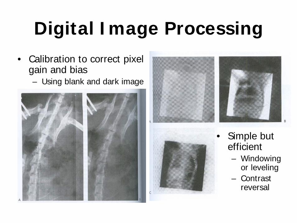
Digital Image Processing• Calibration to correct pixel
gain and bias– Using blank and dark image
• Simple but efficient– Windowing
or leveling – Contrast
reversal
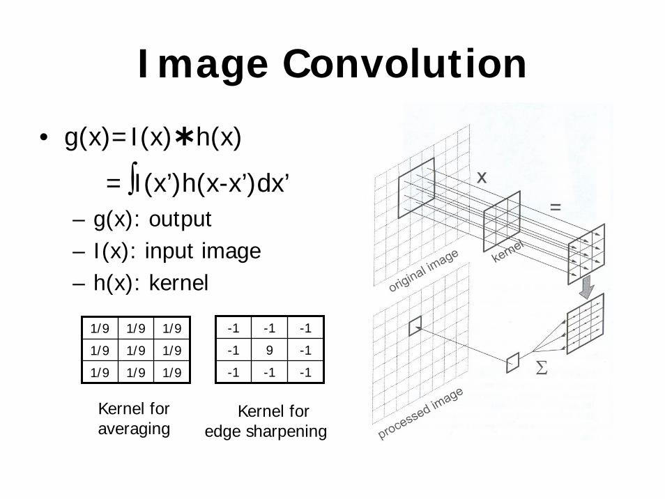
Image Convolution
• g(x)=I(x) h(x)
=∫I(x’)h(x-x’)dx’– g(x): output– I(x): input image– h(x): kernel
1/9 1/9 1/9
1/9 1/9 1/9
1/9 1/9 1/9
-1 -1 -1
-1 9 -1
-1 -1 -1
Kernel for averaging
Kernel for edge sharpening
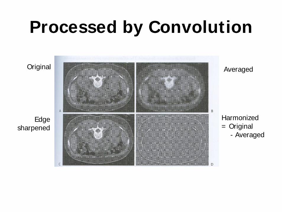
Processed by Convolution
Original Averaged
Edge sharpened
Harmonized = Original
- Averaged
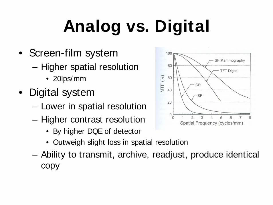
Analog vs. Digital• Screen-film system
– Higher spatial resolution• 20lps/mm
• Digital system– Lower in spatial resolution– Higher contrast resolution
• By higher DQE of detector• Outweigh slight loss in spatial resolution
– Ability to transmit, archive, readjust, produce identical copy
Chapter 12
Digital Radiography
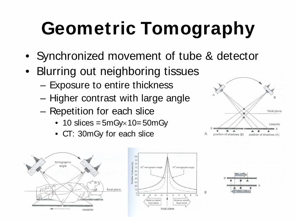
Geometric Tomography• Synchronized movement of tube & detector• Blurring out neighboring tissues
– Exposure to entire thickness– Higher contrast with large angle– Repetition for each slice
• 10 slices =5mGy×10=50mGy• CT: 30mGy for each slice
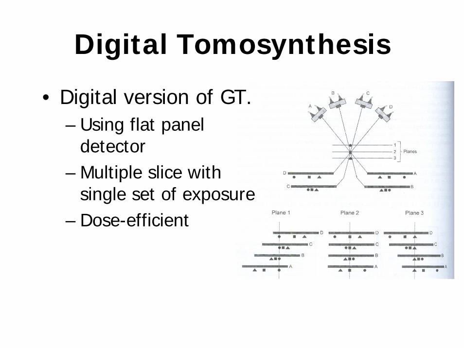
Digital Tomosynthesis
• Digital version of GT.– Using flat panel
detector– Multiple slice with
single set of exposure– Dose-efficient
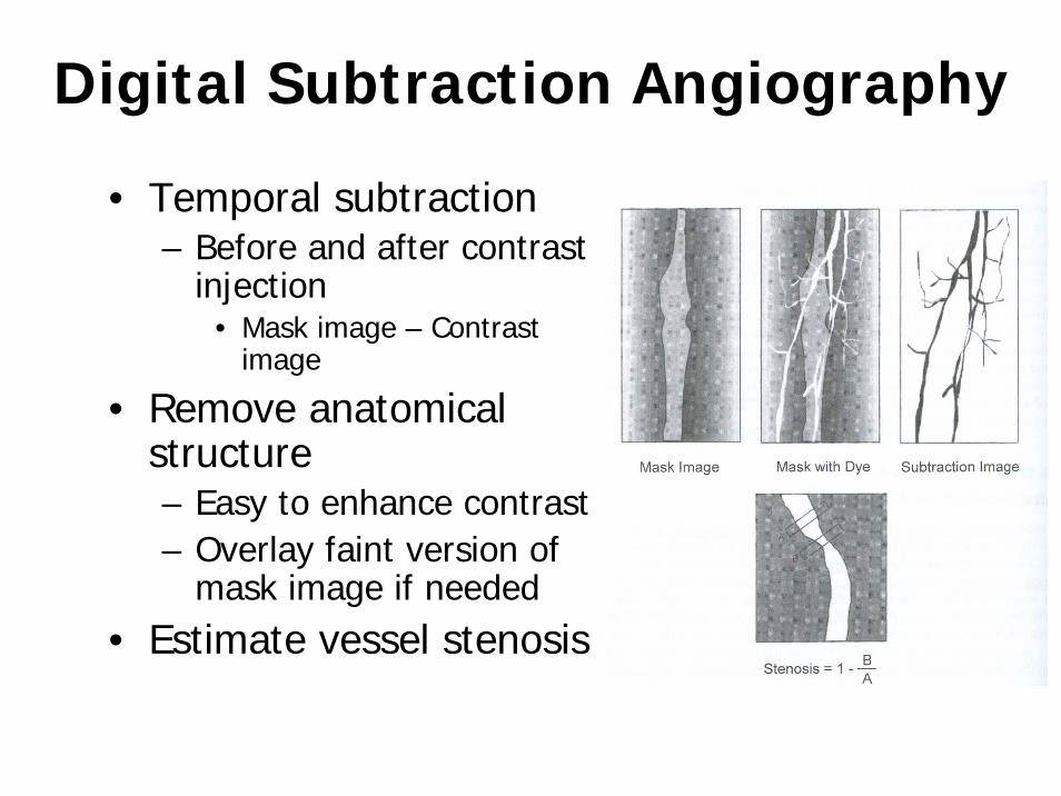
Digital Subtraction Angiography
• Temporal subtraction– Before and after contrast
injection• Mask image – Contrast
image
• Remove anatomical structure– Easy to enhance contrast– Overlay faint version of
mask image if needed• Estimate vessel stenosis
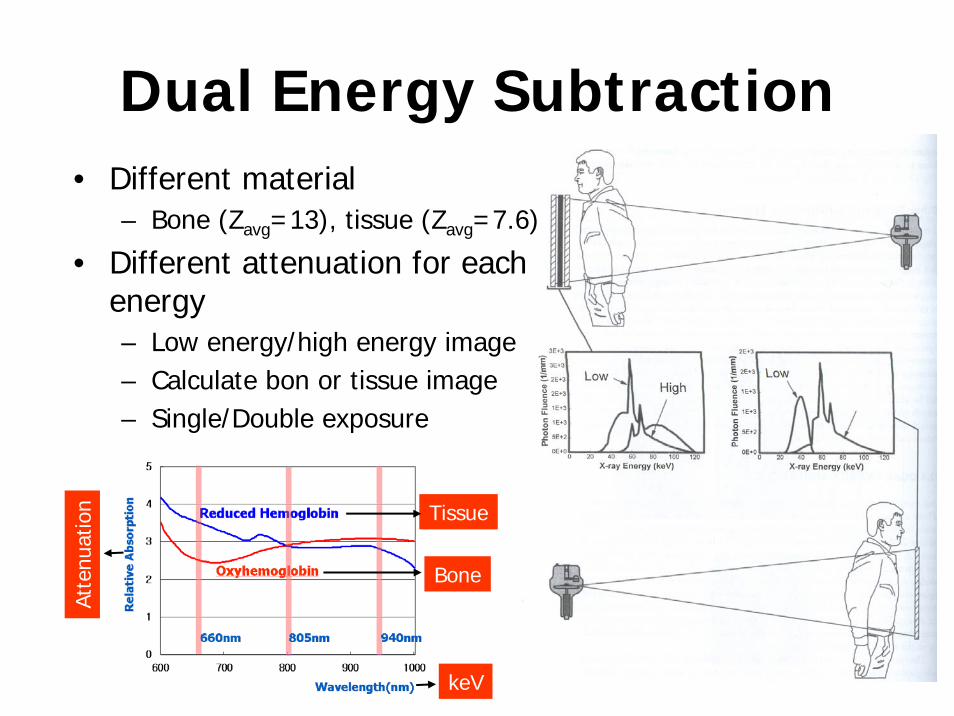
Dual Energy Subtraction• Different material
– Bone (Zavg=13), tissue (Zavg=7.6)
• Different attenuation for each energy– Low energy/high energy image– Calculate bon or tissue image– Single/Double exposure
Tissue
Bone
keV
Atte
nuat
ion
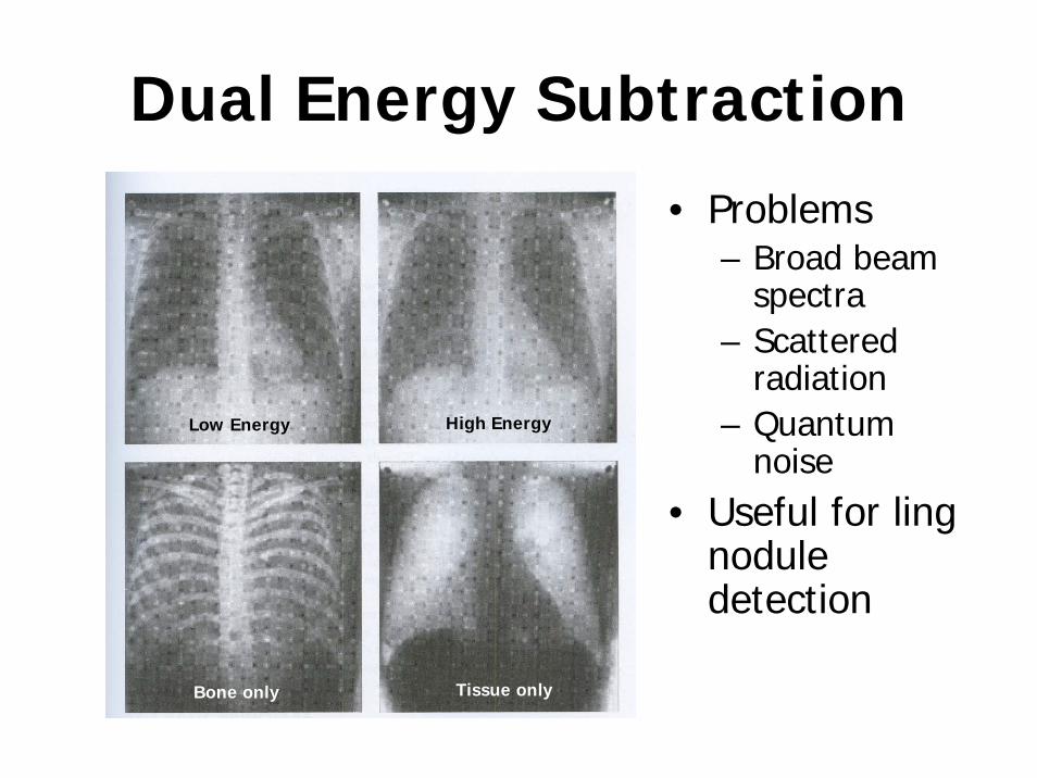
Dual Energy Subtraction
• Problems– Broad beam
spectra– Scattered
radiation– Quantum
noise• Useful for ling
nodule detection
Low Energy High Energy
Bone only Tissue only