Embed Size (px)
Citation preview
Chapter 11
Appendix F: Connecting a0-10V Spindle Speed Control
81
11.1 Introduction
In this chapter we explain how you can connect a 0-10V Spindle Speed Con-trol. A 0-10V Spindle speed control is a small PCB which is able to interfacewith USBCNC V3, V4 and V5B; allowing USBCNC software to control a(Delta) Variable Frequency Drive (VFD) which in its turn can control a(Tekno)motor HF - or electrospindle.
In order to install the 0-10V Spindle Speed Control PCB it is highly rec-ommended to first read and perform Appendix E: Setup of a Delta VFD anda Teknomotor.
By doing so the user can control the (Tekno)motor without USBCNC, whichmight already exclude any errors.
After the user has performed the entire Appendix E procedure, the systemcan be prepared in the following sequence:
First the hardware connection procedure will be discussed:
1. I have a DamenCNC RTR Performance (standard with 0-10VSpindle Speed Control) set and a Delta VFD with a cable as-sembly
2. I have a DamenCNC RTR without a 0-10V Spindle SpeedControl Delta VFD
3. I have a USBCNC CPU V4.0 and a Delta VFD
Afterwards the software setup is explained. The software setup consists ofthe setup of the DELTA VFD, and the setup of USBCNC V5.
82
11.2 Hardware Connection procedure
1. I have a DamenCNC RTR Performance (standardwith 0-10V Spindle Speed Control) set and a Delta VFDwith a cable assembly
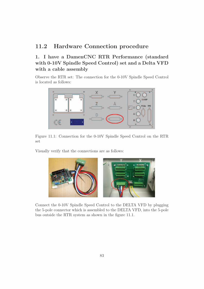
Observe the RTR set: The connection for the 0-10V Spindle Speed Controlis located as follows:
Figure 11.1: Connection for the 0-10V Spindle Speed Control on the RTRset
Visually verify that the connections are as follows:
Connect the 0-10V Spindle Speed Control to the DELTA VFD by pluggingthe 5-pole connector which is assembled to the DELTA VFD, into the 5-polebus outside the RTR system as shown in the figure 11.1.
83
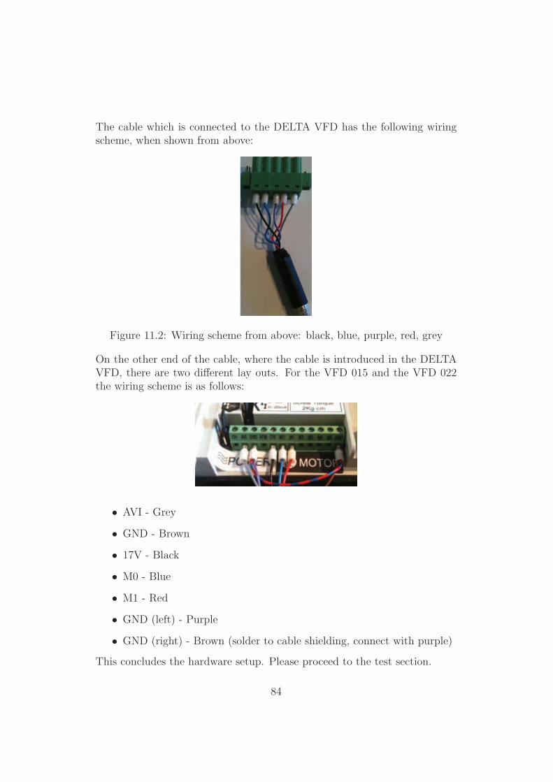
The cable which is connected to the DELTA VFD has the following wiringscheme, when shown from above:
Figure 11.2: Wiring scheme from above: black, blue, purple, red, grey
On the other end of the cable, where the cable is introduced in the DELTAVFD, there are two different lay outs. For the VFD 015 and the VFD 022the wiring scheme is as follows:
• AVI - Grey
• GND - Brown
• 17V - Black
• M0 - Blue
• M1 - Red
• GND (left) - Purple
• GND (right) - Brown (solder to cable shielding, connect with purple)
This concludes the hardware setup. Please proceed to the test section.
84
2. I have a DamenCNC RTR without a 0-10V SpindleSpeed Control Delta VFD
When there is no 0-10V Spindle Control PCB already built in the RTR sys-tem, it has to be build in first.
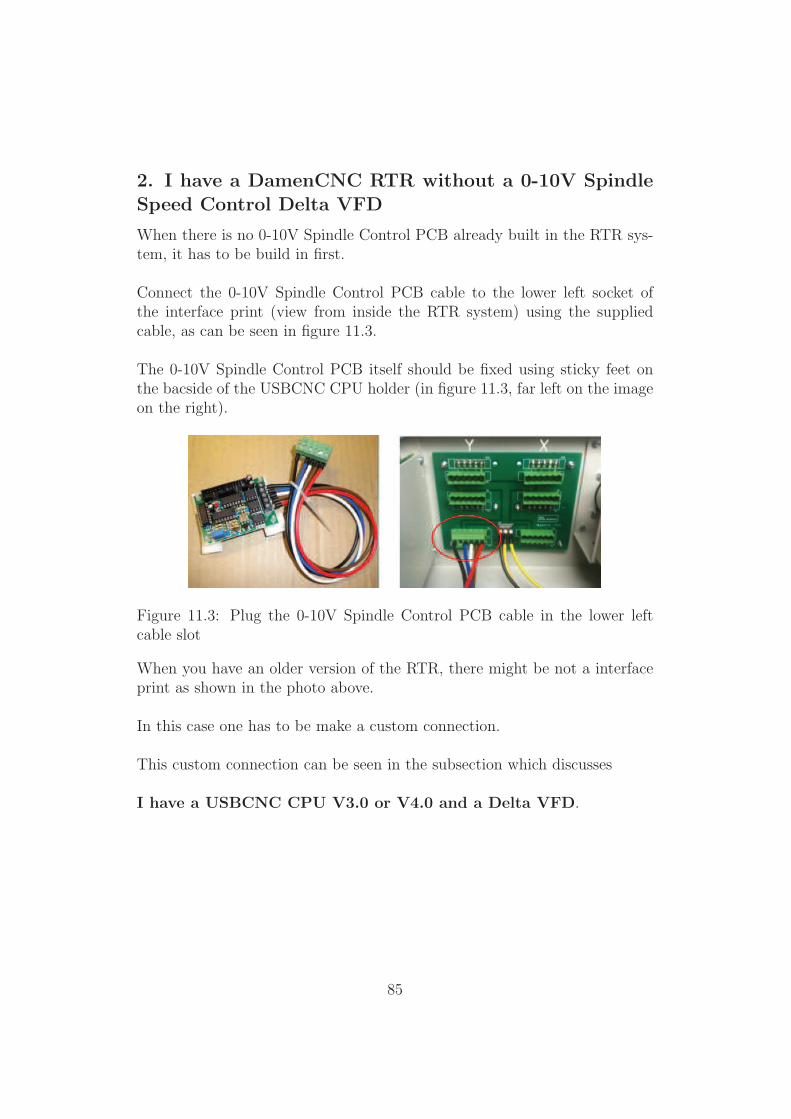
Connect the 0-10V Spindle Control PCB cable to the lower left socket ofthe interface print (view from inside the RTR system) using the suppliedcable, as can be seen in figure 11.3.
The 0-10V Spindle Control PCB itself should be fixed using sticky feet onthe bacside of the USBCNC CPU holder (in figure 11.3, far left on the imageon the right).
Figure 11.3: Plug the 0-10V Spindle Control PCB cable in the lower leftcable slot
When you have an older version of the RTR, there might be not a interfaceprint as shown in the photo above.
In this case one has to be make a custom connection.
This custom connection can be seen in the subsection which discusses
I have a USBCNC CPU V3.0 or V4.0 and a Delta VFD.
85
Connecting the 0-10V Spindle speed control PCB to aUSBCNC CPU
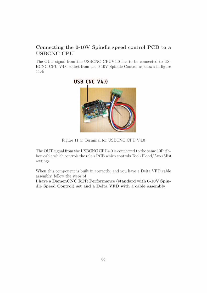
The OUT signal from the USBCNC CPUV4.0 has to be connected to US-BCNC CPU V4.0 socket from the 0-10V Spindle Control as shown in figure11.4:
Figure 11.4: Terminal for USBCNC CPU V4.0
The OUT signal from the USBCNC CPU4.0 is connected to the same 10P rib-bon cable which controls the relais PCB which controls Tool/Flood/Aux/Mistsettings.
When this component is built in correctly, and you have a Delta VFD cableassembly, follow the steps ofI have a DamenCNC RTR Performance (standard with 0-10V Spin-dle Speed Control) set and a Delta VFD with a cable assembly.
86
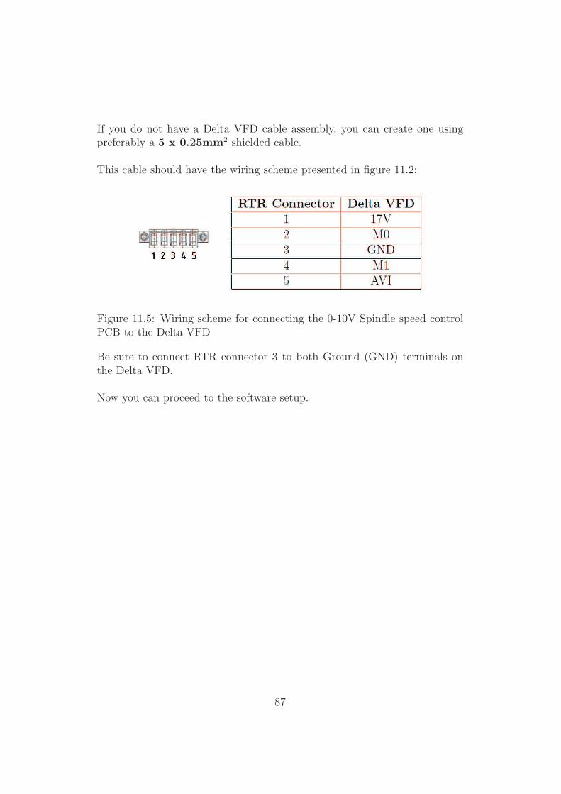
If you do not have a Delta VFD cable assembly, you can create one usingpreferably a 5 x 0.25mm2 shielded cable.
This cable should have the wiring scheme presented in figure 11.2:
Figure 11.5: Wiring scheme for connecting the 0-10V Spindle speed controlPCB to the Delta VFD
Be sure to connect RTR connector 3 to both Ground (GND) terminals onthe Delta VFD.
Now you can proceed to the software setup.
87
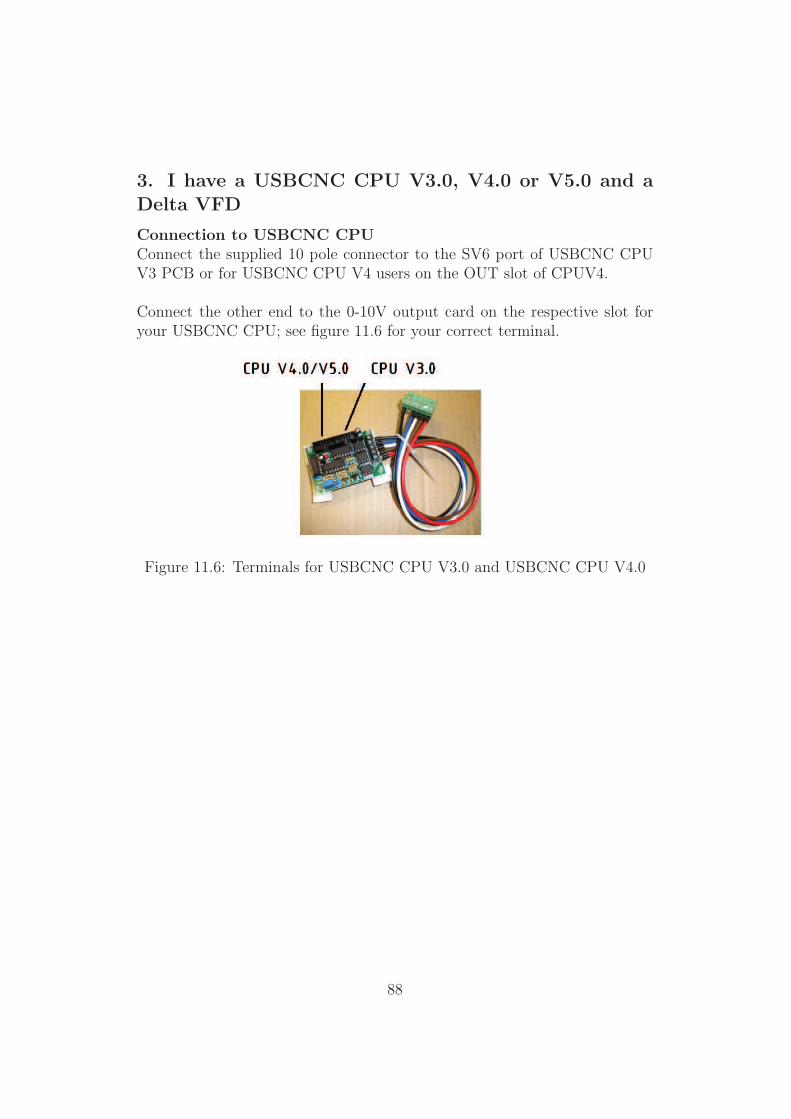
3. I have a USBCNC CPU V3.0, V4.0 or V5.0 and aDelta VFD
Connection to USBCNC CPUConnect the supplied 10 pole connector to the SV6 port of USBCNC CPUV3 PCB or for USBCNC CPU V4 users on the OUT slot of CPUV4.
Connect the other end to the 0-10V output card on the respective slot foryour USBCNC CPU; see figure 11.6 for your correct terminal.
Figure 11.6: Terminals for USBCNC CPU V3.0 and USBCNC CPU V4.0
88
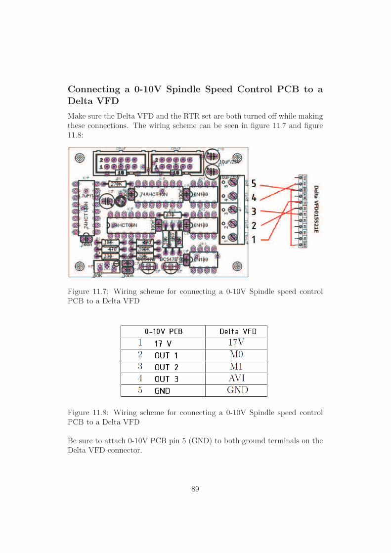
Connecting a 0-10V Spindle Speed Control PCB to aDelta VFD
Make sure the Delta VFD and the RTR set are both turned off while makingthese connections. The wiring scheme can be seen in figure 11.7 and figure11.8:
Figure 11.7: Wiring scheme for connecting a 0-10V Spindle speed controlPCB to a Delta VFD
Figure 11.8: Wiring scheme for connecting a 0-10V Spindle speed controlPCB to a Delta VFD
Be sure to attach 0-10V PCB pin 5 (GND) to both ground terminals on theDelta VFD connector.
89

Note:Use a (twisted) shielded cable for the above mentioned connections.
The shielding of the used cable should only be connected at the connec-tor at the side of the drive (or the RTR side of the cable).
Always connect the shielding of the used cable to the Earth terminal onthe DamenCNC motor interface card.
Now you can proceed to the software setup.
90
11.3 Software setup
The software setup consists of two parts.
1. Setup of the Delta VFD
2. Setup of USBCNC Software
91
Software setup of the Delta VFD
The Delta VFD should be set up such that there is a communication be-tween the USBCNC Software and the Delta VFD. This communication canbe established by performing the following steps:
Unplug the connection between the Delta VFD and the 0-10V Spindle speedcontrol PCB.
Apply power to the VFD; please bear in mind that you should always usethe Delta VFD in an environment where your 220V socket is NOT attachedto a group which supplies power to any important electronical (data) de-vices. This is because the Delta VFD might trigger your RCD (Dutch:aardlekschakelaar)!
In addition, NEVER use the 220V socket from your RTR set; instead usea seperate wall socket!
Usually a VFD obtains its inputs from the potentiometer and the interface.Since we want to control the speeds via a 0-10V input we need to changethe parameters of the drives such that it takes the speed input at the 0-10Vinput. In table 11.1 one can find the parameters which need to be adjusted.After table 11.1 we explain how you can adjust each parameter.
92
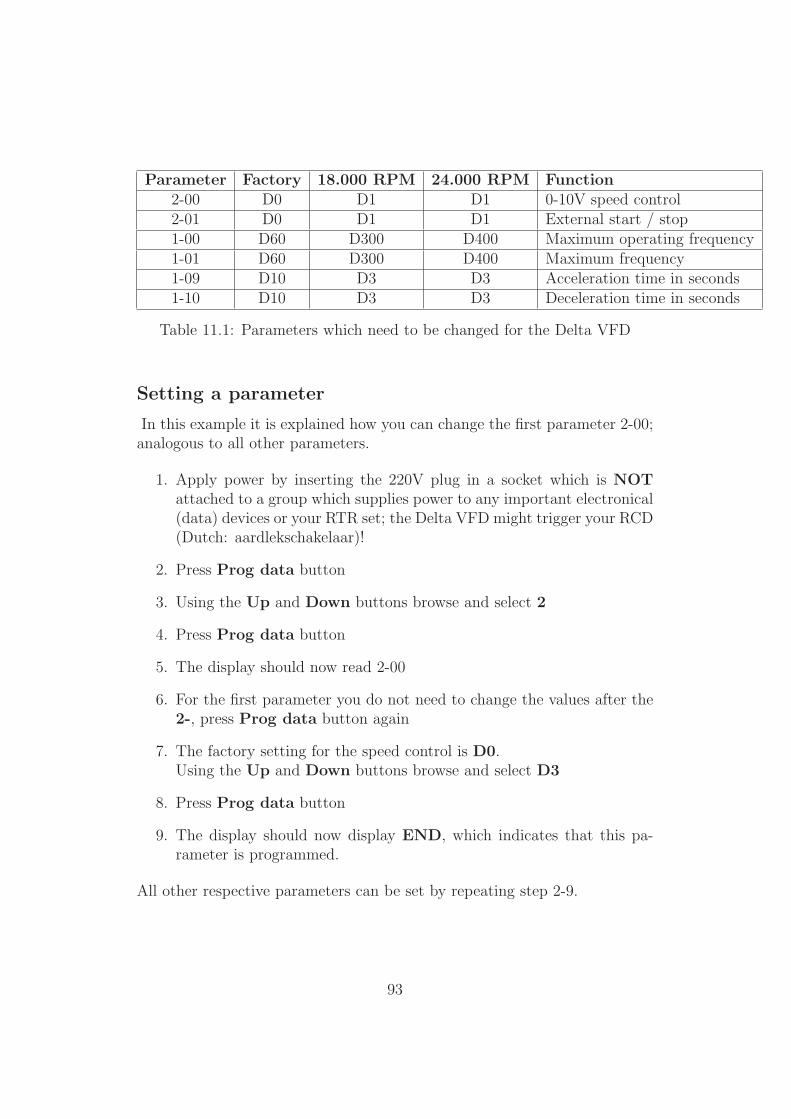
Parameter Factory 18.000 RPM 24.000 RPM Function2-00 D0 D1 D1 0-10V speed control2-01 D0 D1 D1 External start / stop1-00 D60 D300 D400 Maximum operating frequency1-01 D60 D300 D400 Maximum frequency1-09 D10 D3 D3 Acceleration time in seconds1-10 D10 D3 D3 Deceleration time in seconds
Table 11.1: Parameters which need to be changed for the Delta VFD
Setting a parameter
In this example it is explained how you can change the first parameter 2-00;analogous to all other parameters.
1. Apply power by inserting the 220V plug in a socket which is NOTattached to a group which supplies power to any important electronical(data) devices or your RTR set; the Delta VFD might trigger your RCD(Dutch: aardlekschakelaar)!
2. Press Prog data button
3. Using the Up and Down buttons browse and select 2
4. Press Prog data button
5. The display should now read 2-00
6. For the first parameter you do not need to change the values after the2-, press Prog data button again
7. The factory setting for the speed control is D0.Using the Up and Down buttons browse and select D3
8. Press Prog data button
9. The display should now display END, which indicates that this pa-rameter is programmed.
All other respective parameters can be set by repeating step 2-9.
93
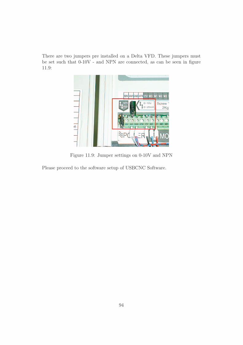
There are two jumpers pre installed on a Delta VFD. These jumpers mustbe set such that 0-10V - and NPN are connected, as can be seen in figure11.9:
Figure 11.9: Jumper settings on 0-10V and NPN
Please proceed to the software setup of USBCNC Software.
94

Software setup of USBCNC Software
The Software setup of USBCNC consists of three steps.
1. Set the correct outputs
2. Testing without a Teknomotor
3. Testing with a Teknomotor
95
1. Set the correct outputs
Navigate in the USBCNC environment to the Tab Setup.
Make sure that under the Spindle box the parameters PWM is checked.
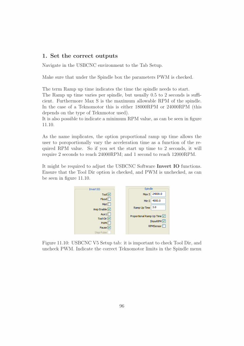
The term Ramp up time indicates the time the spindle needs to start.The Ramp up time varies per spindle, but usually 0.5 to 2 seconds is suffi-cient. Furthermore Max S is the maximum allowable RPM of the spindle.In the case of a Teknomotor this is either 18000RPM or 24000RPM (thisdepends on the type of Teknmotor used).It is also possible to indicate a minimum RPM value, as can be seen in figure11.10.
As the name implicates, the option proportional ramp up time allows theuser to poroportionally vary the acceleration time as a function of the re-quired RPM value. So if you set the start up time to 2 seconds, it willrequire 2 seconds to reach 24000RPM; and 1 second to reach 12000RPM.
It might be required to adjust the USBCNC Software Invert IO functions.Ensure that the Tool Dir option is checked, and PWM is unchecked, as canbe seen in figure 11.10.
Figure 11.10: USBCNC V5 Setup tab: it is important to check Tool Dir, anduncheck PWM. Indicate the correct Teknomotor limits in the Spindle menu
96
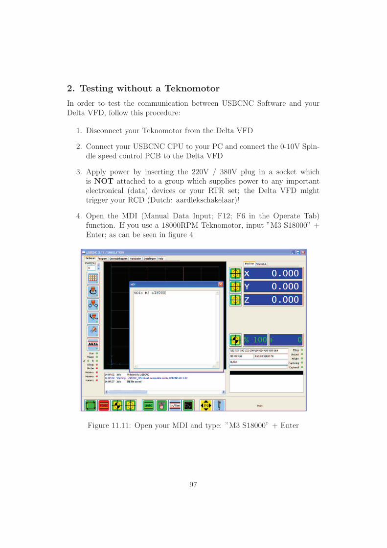
2. Testing without a Teknomotor
In order to test the communication between USBCNC Software and yourDelta VFD, follow this procedure:
1. Disconnect your Teknomotor from the Delta VFD
2. Connect your USBCNC CPU to your PC and connect the 0-10V Spin-dle speed control PCB to the Delta VFD
3. Apply power by inserting the 220V / 380V plug in a socket whichis NOT attached to a group which supplies power to any importantelectronical (data) devices or your RTR set; the Delta VFD mighttrigger your RCD (Dutch: aardlekschakelaar)!
4. Open the MDI (Manual Data Input; F12; F6 in the Operate Tab)function. If you use a 18000RPM Teknomotor, input ”M3 S18000” +Enter; as can be seen in figure 4
Figure 11.11: Open your MDI and type: ”M3 S18000” + Enter
97
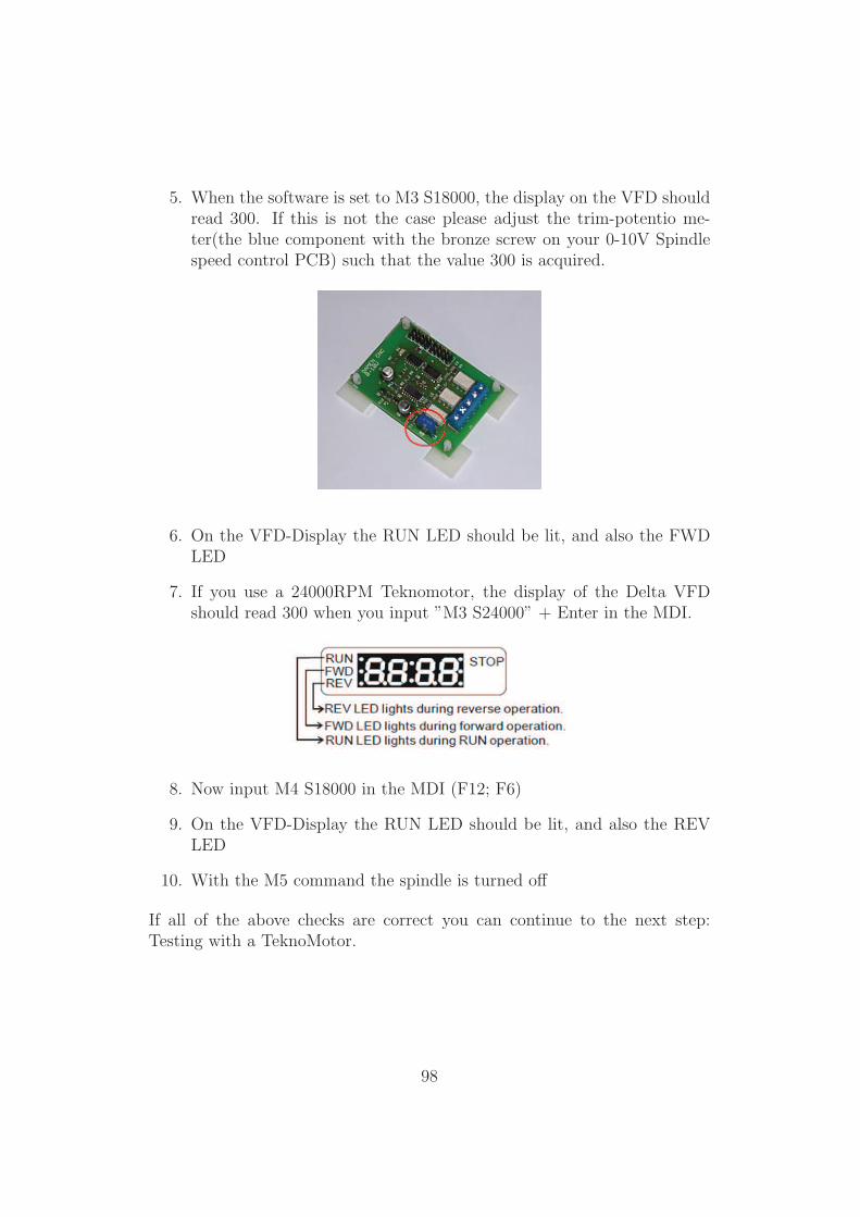
5. When the software is set to M3 S18000, the display on the VFD shouldread 300. If this is not the case please adjust the trim-potentio me-ter(the blue component with the bronze screw on your 0-10V Spindlespeed control PCB) such that the value 300 is acquired.
6. On the VFD-Display the RUN LED should be lit, and also the FWDLED
7. If you use a 24000RPM Teknomotor, the display of the Delta VFDshould read 300 when you input ”M3 S24000” + Enter in the MDI.
8. Now input M4 S18000 in the MDI (F12; F6)
9. On the VFD-Display the RUN LED should be lit, and also the REVLED
10. With the M5 command the spindle is turned off
If all of the above checks are correct you can continue to the next step:Testing with a TeknoMotor.
98
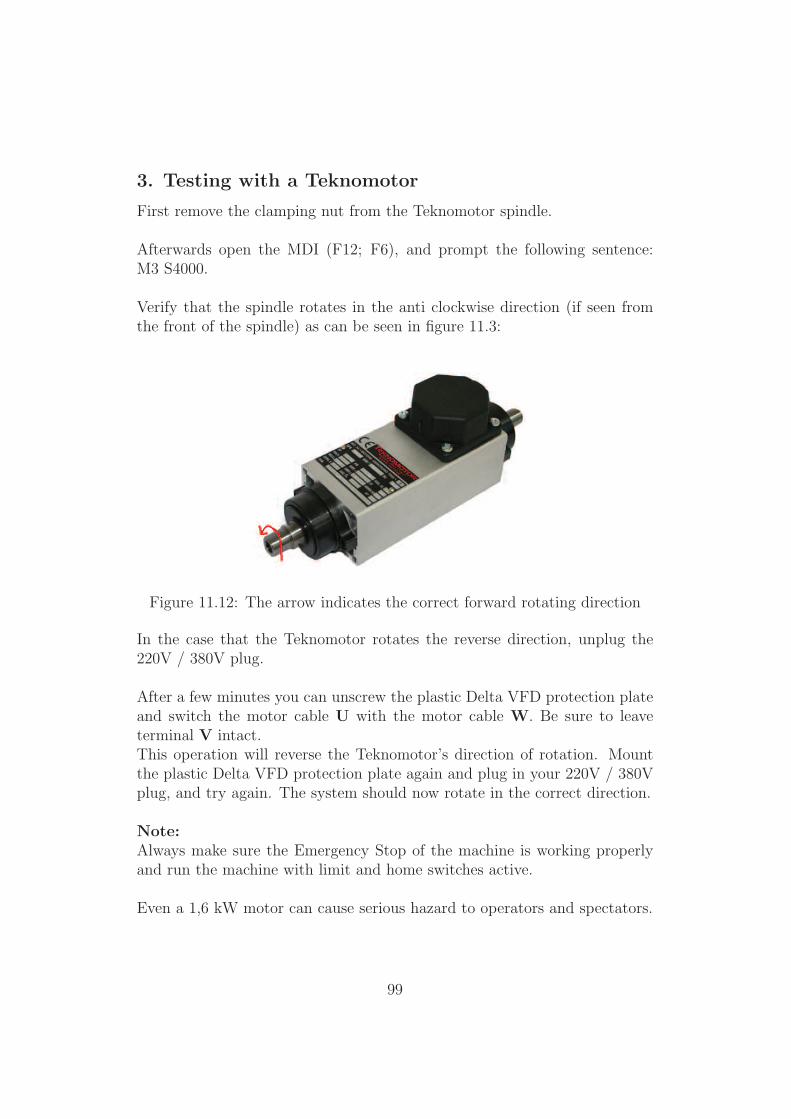
3. Testing with a Teknomotor
First remove the clamping nut from the Teknomotor spindle.
Afterwards open the MDI (F12; F6), and prompt the following sentence:M3 S4000.
Verify that the spindle rotates in the anti clockwise direction (if seen fromthe front of the spindle) as can be seen in figure 11.3:
Figure 11.12: The arrow indicates the correct forward rotating direction
In the case that the Teknomotor rotates the reverse direction, unplug the220V / 380V plug.
After a few minutes you can unscrew the plastic Delta VFD protection plateand switch the motor cable U with the motor cable W. Be sure to leaveterminal V intact.This operation will reverse the Teknomotor’s direction of rotation. Mountthe plastic Delta VFD protection plate again and plug in your 220V / 380Vplug, and try again. The system should now rotate in the correct direction.
Note:Always make sure the Emergency Stop of the machine is working properlyand run the machine with limit and home switches active.
Even a 1,6 kW motor can cause serious hazard to operators and spectators.
99