Embed Size (px)
Citation preview

213
Chapter 10-x
−30 −25
−7.000−6.000−5.000−4.000−3.000−2.000−1.000
0
1.0002.0003.0004.0005.0006.0007.0008.0009.000
10.000
−8.000−20 −15 −10 −5 0 5
Displacement [mm]
Collapse −
1st crack
Collapse +Steel yield
Load
[kN
]
10 15 20 25 30 35 40
Authors:Adrian BekőPeter Roško
10Testing of Stiff Shear Walls
MotivationThe scaling of specimens for laboratory testing limits the applicability of the test re-
sults. A full scale test of a reinforced concrete wall with a thickness of 40 cm was desired.
Main ResultsFive specimens have been cast and tested at JRC in the ELSA laboratory in Ispra. For
the first time a test on such a large specimen working in shear was realized. A prediction contest was organized and a wide participation in the tests was enabled. The data are made available for any future investigations.
214
10 Testing of Stiff Shear Walls
10-1 IntroductionReinforced concrete shear walls are frequently used in civil engineering as structural
elements resisting horizontal forces in the plane of the wall. The stiffness of the shear wall has to keep drifts within reasonable limits. During recent earthquakes in the world many structures (among them also reinforced concrete walls) collapsed suddenly and led to catastrophic failures which occurred due to dynamic shear loading. Consequences of earthquakes have proven the need to study thoroughly the shear mechanism of rein-forced concrete walls. Therefore the scientific research in this area is very intensive and has resulted in many experimental and numerical tests in the last years.
Because of the parameter variability, each experimental or numerical research is but a contribution to the knowledge base. The applicability of results is limited by the type of wall and parameter subspace. A number of failure modes can occur depending on param-eters such as the type of cross-section, reinforcement detailing and quantities, properties of reinforcing steel, concrete compressive strength and boundary conditions. Complex destructive phenomena include concrete cracking, interaction effects between steel and concrete, steel yielding and concrete crushing in compression. It is not simple to general-ize any given experimental or numerical test because of reasons mentioned above. When a test studies a specific type of structure and well defined loading, the outcome is of great interest.
Generally, shear walls are divided into two groups based on their geometry: high-rise or tall and low-rise or squat/short shear walls. High-rise shear walls are governed by flex-ural behaviour similar to a cantilever beam. The flexural behaviour of reinforced concrete walls has been examined and it is theoretically described (see historical references below or a more current one by [Orakcal et al., 2006]). The behaviour of low-rise shear walls is governed mainly by shear behaviour. Although there has been considerable activity directed towards low-rise shear walls this area of research is still in progress. One of the reasons is that low-rise shear walls are frequently used in nuclear power plants. Investiga-tions presented here were focused on a low-rise wall specifically a more massive speci-men which could be classified as a thick shear wall. Here we present the results of a joint research activity to study a full scale shear wall with a thickness of 400 mm.
Our research presented here builds on the contemporary knowledge in the field. His-torical development of the research into reinforced concrete shear walls can be outlined by certain milestones.
Some of the first test results of low-rise shear walls under static loads are available in the literature of the fifties by [Galletly, 1952]. Advancing the subject were [Benjamin and Williams, 1957; 1960] with significant experimental research. During the 1960s most experimental research aimed at understanding the behaviour of reinforced concrete el-ements was directed towards moment resisting frames. Later in the 1970s the interest in the seismic behaviour grew and induced the experimental investigation of reinforced concrete walls. [Paulay, 1975] presented design aspects of shear walls for seismic areas. Studies of [Barda, 1972] led to the improved wall design provisions in ACI 318-71, includ-ing seismic requirements. Other wall tests of the decade were conducted by [Iliya and Bertero, 1980; Oesterle et al., 1976; 1979; Vallenas et al., 1979] and. In the coming years
215
Experimental Testing of Shear Walls 10-2
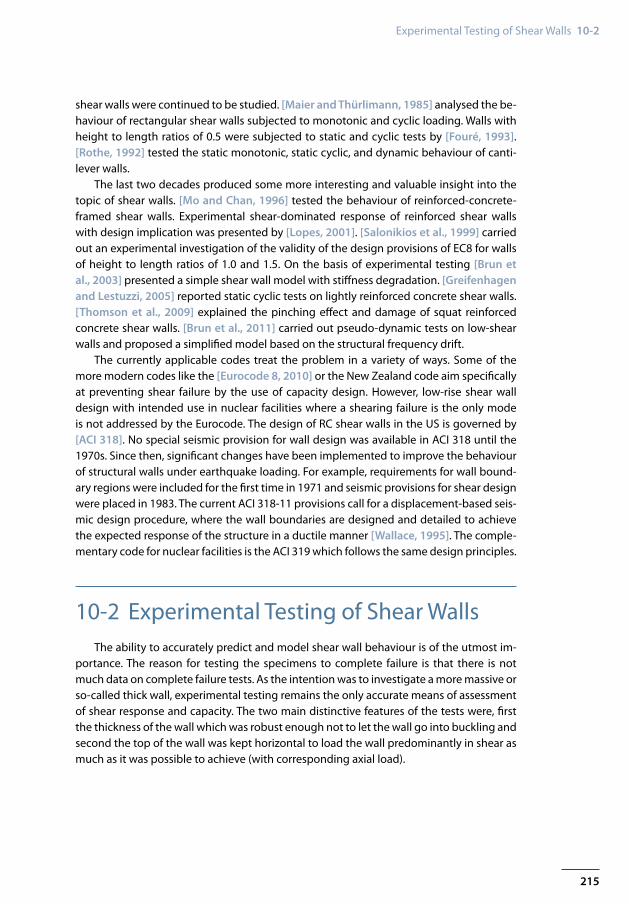
shear walls were continued to be studied. [Maier and Thürlimann, 1985] analysed the be-haviour of rectangular shear walls subjected to monotonic and cyclic loading. Walls with height to length ratios of 0.5 were subjected to static and cyclic tests by [Fouré, 1993]. [Rothe, 1992] tested the static monotonic, static cyclic, and dynamic behaviour of canti-lever walls.
The last two decades produced some more interesting and valuable insight into the topic of shear walls. [Mo and Chan, 1996] tested the behaviour of reinforced-concrete-framed shear walls. Experimental shear-dominated response of reinforced shear walls with design implication was presented by [Lopes, 2001]. [Salonikios et al., 1999] carried out an experimental investigation of the validity of the design provisions of EC8 for walls of height to length ratios of 1.0 and 1.5. On the basis of experimental testing [Brun et al., 2003] presented a simple shear wall model with stiffness degradation. [Greifenhagen and Lestuzzi, 2005] reported static cyclic tests on lightly reinforced concrete shear walls. [Thomson et al., 2009] explained the pinching effect and damage of squat reinforced concrete shear walls. [Brun et al., 2011] carried out pseudo-dynamic tests on low-shear walls and proposed a simplified model based on the structural frequency drift.
The currently applicable codes treat the problem in a variety of ways. Some of the more modern codes like the [Eurocode 8, 2010] or the New Zealand code aim specifically at preventing shear failure by the use of capacity design. However, low-rise shear wall design with intended use in nuclear facilities where a shearing failure is the only mode is not addressed by the Eurocode. The design of RC shear walls in the US is governed by [ACI 318]. No special seismic provision for wall design was available in ACI 318 until the 1970s. Since then, significant changes have been implemented to improve the behaviour of structural walls under earthquake loading. For example, requirements for wall bound-ary regions were included for the first time in 1971 and seismic provisions for shear design were placed in 1983. The current ACI 318-11 provisions call for a displacement-based seis-mic design procedure, where the wall boundaries are designed and detailed to achieve the expected response of the structure in a ductile manner [Wallace, 1995]. The comple-mentary code for nuclear facilities is the ACI 319 which follows the same design principles.
10-2 Experimental Testing of Shear WallsThe ability to accurately predict and model shear wall behaviour is of the utmost im-
portance. The reason for testing the specimens to complete failure is that there is not much data on complete failure tests. As the intention was to investigate a more massive or so-called thick wall, experimental testing remains the only accurate means of assessment of shear response and capacity. The two main distinctive features of the tests were, first the thickness of the wall which was robust enough not to let the wall go into buckling and second the top of the wall was kept horizontal to load the wall predominantly in shear as much as it was possible to achieve (with corresponding axial load).
216
10 Testing of Stiff Shear Walls
33
3 12 10 10
34
400
300
300
5050
8012
080
125
125
4042.5 42.5120
80
5 7Edge detail
8
3 2 2∅16
2
7 8
2∅16
1 6∅16
1 6∅16
4 22∅16
3 6∅16
5 19∅16
4 22∅16
3 6∅16
3 6∅165 19∅16
6 36∅10
5 19∅16
7 6∅168 12∅10
Edge detail
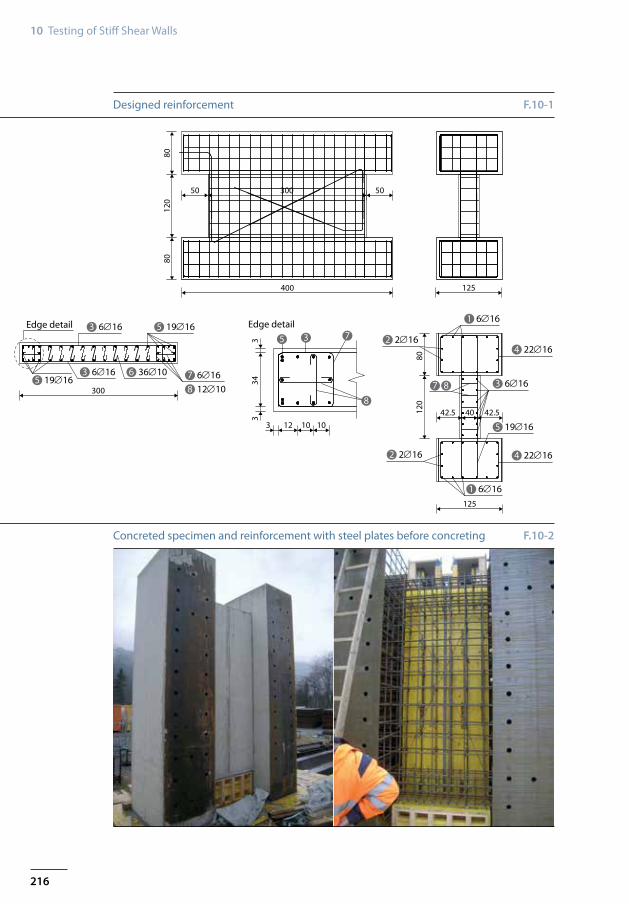
Designed reinforcement
Concreted specimen and reinforcement with steel plates before concreting
F.10-1
F.10-2
217
Experimental Testing of Shear Walls 10-2
800
2800
4000
200
260
420
240
240
160
160
160
160
800
160
160
160
320 280 280 280 280 280 280 280 280 280 320 420
290 290 290 290 290 290 290 290 290 290 290 290 260
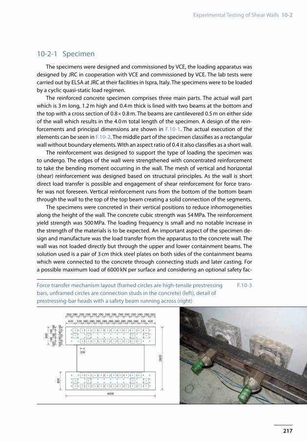
Force transfer mechanism layout (framed circles are high-tensile prestressing bars, unframed circles are connection studs in the concrete) (left), detail of prestressing-bar heads with a safety beam running across (right)
F.10-3
10-2-1 Specimen
The specimens were designed and commissioned by VCE, the loading apparatus was designed by JRC in cooperation with VCE and commissioned by VCE. The lab tests were carried out by ELSA at JRC at their facilities in Ispra, Italy. The specimens were to be loaded by a cyclic quasi-static load regimen.
The reinforced concrete specimen comprises three main parts. The actual wall part which is 3 m long, 1.2 m high and 0.4 m thick is lined with two beams at the bottom and the top with a cross section of 0.8 × 0.8 m. The beams are cantilevered 0.5 m on either side of the wall which results in the 4.0 m total length of the specimen. A design of the rein-forcements and principal dimensions are shown in F.10-1. The actual execution of the elements can be seen in F.10-2. The middle part of the specimen classifies as a rectangular wall without boundary elements. With an aspect ratio of 0.4 it also classifies as a short wall.
The reinforcement was designed to support the type of loading the specimen was to undergo. The edges of the wall were strengthened with concentrated reinforcement to take the bending moment occurring in the wall. The mesh of vertical and horizontal (shear) reinforcement was designed based on structural principles. As the wall is short direct load transfer is possible and engagement of shear reinforcement for force trans-fer was not foreseen. Vertical reinforcement runs from the bottom of the bottom beam through the wall to the top of the top beam creating a solid connection of the segments.
The specimens were concreted in their vertical positions to reduce inhomogeneities along the height of the wall. The concrete cubic strength was 54 MPa. The reinforcement yield strength was 500 MPa. The loading frequency is small and no notable increase in the strength of the materials is to be expected. An important aspect of the specimen de-sign and manufacture was the load transfer from the apparatus to the concrete wall. The wall was not loaded directly but through the upper and lower containment beams. The solution used is a pair of 3 cm thick steel plates on both sides of the containment beams which were connected to the concrete through connecting studs and later casting. For a possible maximum load of 6000 kN per surface and considering an optional safety fac-
218
10 Testing of Stiff Shear Walls
PL17 / PL80*1460
PL4 / PL120*1030
PL4 / PL120*1030
PL17 / PL80*1460
PL18 / PL180*600
PL17 / PL80*1460
PL17 / PL80*1460
PL17 / PL80*1460
PL17 / PL80*1460
PL17 / PL80*1460
PL18 / PL180*600
PL18 / PL180*600
PL18 / PL180*600
PL4 / PL120*1030
PL4 / PL120*1030
PL5 / PL120*800
PL5 / PL120*800
PL8 / PL50*365
PL8 / PL50*365
PL8 / PL50*365
PL8 / PL50*365
PL16 / PL50*340
PL16 / PL50*340
PL16 / PL50*340
PL5 / PL120*800
PL5 / PL120*800
PL3 / PL100*340
PL3 / PL100*340
PL16 / PL50*340
PL16 / PL50*340
PL16 / PL50*340PL16 / PL50*340
PL16 / PL50*340 PL17 / PL80*1460
1 / PL120*1560
1 / PL120*1560
2 / PL120*11322 / PL120*1132
PL3 / PL100*340
PL3 / PL100*340
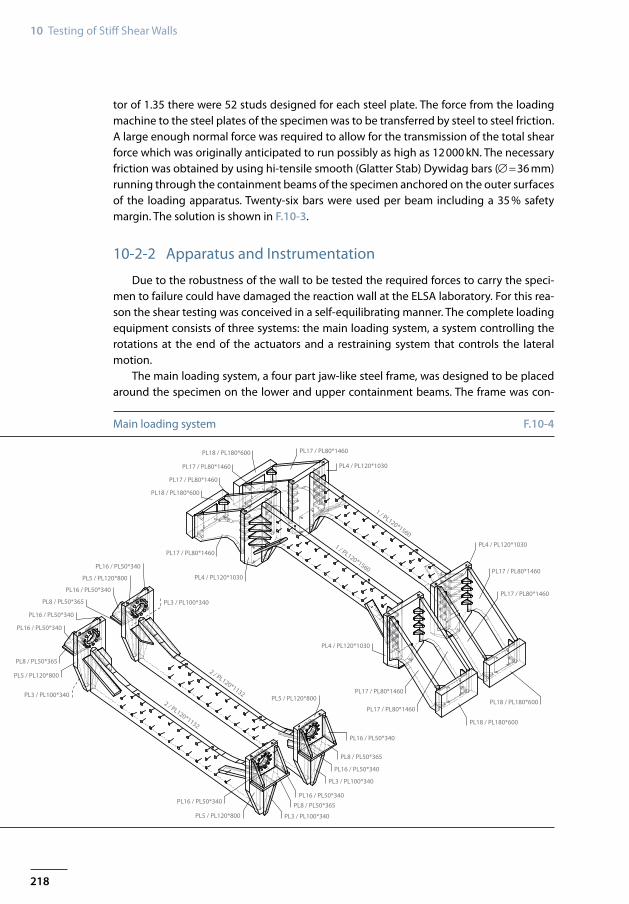
Main loading system F.10-4
tor of 1.35 there were 52 studs designed for each steel plate. The force from the loading machine to the steel plates of the specimen was to be transferred by steel to steel friction. A large enough normal force was required to allow for the transmission of the total shear force which was originally anticipated to run possibly as high as 12000 kN. The necessary friction was obtained by using hi-tensile smooth (Glatter Stab) Dywidag bars (∅=36 mm) running through the containment beams of the specimen anchored on the outer surfaces of the loading apparatus. Twenty-six bars were used per beam including a 35 % safety margin. The solution is shown in F.10-3.
10-2-2 Apparatus and Instrumentation
Due to the robustness of the wall to be tested the required forces to carry the speci-men to failure could have damaged the reaction wall at the ELSA laboratory. For this rea-son the shear testing was conceived in a self-equilibrating manner. The complete loading equipment consists of three systems: the main loading system, a system controlling the rotations at the end of the actuators and a restraining system that controls the lateral motion.
The main loading system, a four part jaw-like steel frame, was designed to be placed around the specimen on the lower and upper containment beams. The frame was con-
219
Experimental Testing of Shear Walls 10-2
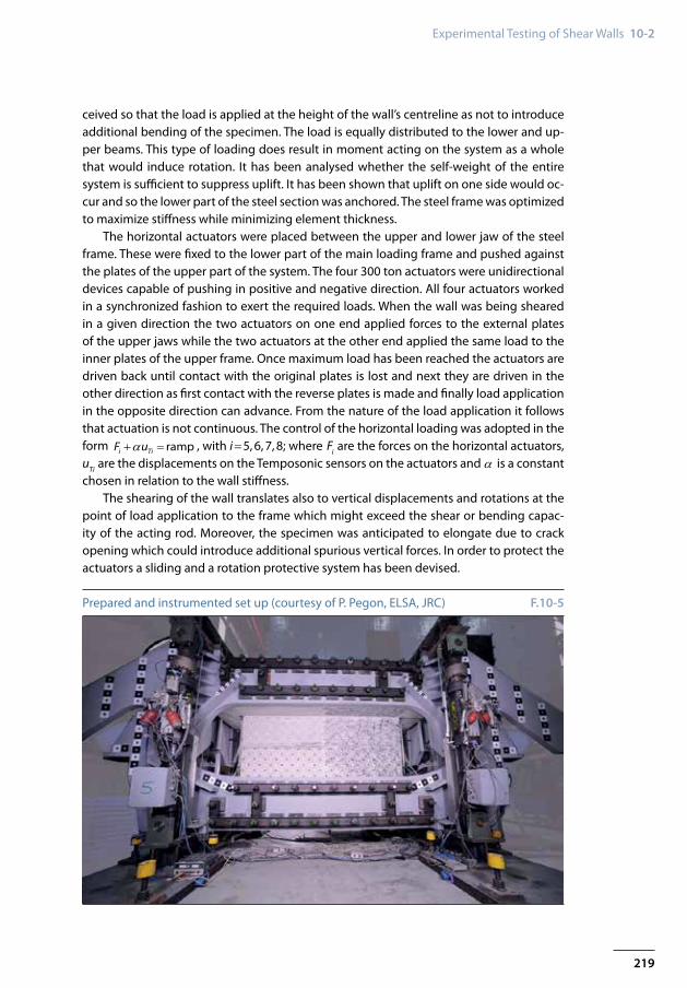
Prepared and instrumented set up (courtesy of P. Pegon, ELSA, JRC) F.10-5
ceived so that the load is applied at the height of the wall’s centreline as not to introduce additional bending of the specimen. The load is equally distributed to the lower and up-per beams. This type of loading does result in moment acting on the system as a whole that would induce rotation. It has been analysed whether the self-weight of the entire system is sufficient to suppress uplift. It has been shown that uplift on one side would oc-cur and so the lower part of the steel section was anchored. The steel frame was optimized to maximize stiffness while minimizing element thickness.
The horizontal actuators were placed between the upper and lower jaw of the steel frame. These were fixed to the lower part of the main loading frame and pushed against the plates of the upper part of the system. The four 300 ton actuators were unidirectional devices capable of pushing in positive and negative direction. All four actuators worked in a synchronized fashion to exert the required loads. When the wall was being sheared in a given direction the two actuators on one end applied forces to the external plates of the upper jaws while the two actuators at the other end applied the same load to the inner plates of the upper frame. Once maximum load has been reached the actuators are driven back until contact with the original plates is lost and next they are driven in the other direction as first contact with the reverse plates is made and finally load application in the opposite direction can advance. From the nature of the load application it follows that actuation is not continuous. The control of the horizontal loading was adopted in the form α+ = rampi TiF u , with i=5, 6, 7, 8; where Fi are the forces on the horizontal actuators, uTi are the displacements on the Temposonic sensors on the actuators and α is a constant chosen in relation to the wall stiffness.
The shearing of the wall translates also to vertical displacements and rotations at the point of load application to the frame which might exceed the shear or bending capac-ity of the acting rod. Moreover, the specimen was anticipated to elongate due to crack opening which could introduce additional spurious vertical forces. In order to protect the actuators a sliding and a rotation protective system has been devised.
220
10 Testing of Stiff Shear Walls
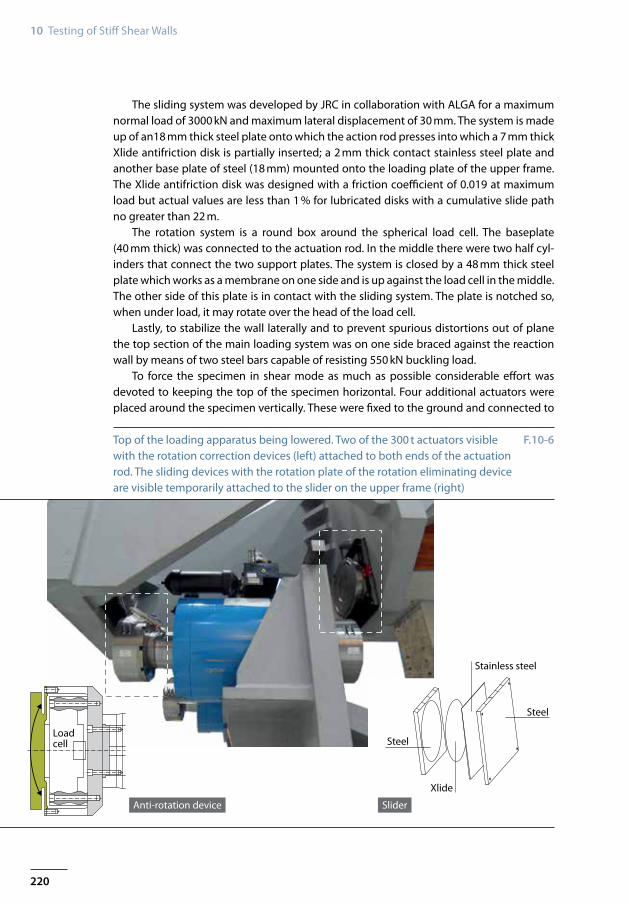
Steel
Stainless steel
Steel
Xlide
Loadcell
Anti-rotation device Slider
Top of the loading apparatus being lowered. Two of the 300 t actuators visible with the rotation correction devices (left) attached to both ends of the actuation rod. The sliding devices with the rotation plate of the rotation eliminating device are visible temporarily attached to the slider on the upper frame (right)
F.10-6
The sliding system was developed by JRC in collaboration with ALGA for a maximum normal load of 3000 kN and maximum lateral displacement of 30 mm. The system is made up of an18 mm thick steel plate onto which the action rod presses into which a 7 mm thick Xlide antifriction disk is partially inserted; a 2 mm thick contact stainless steel plate and another base plate of steel (18 mm) mounted onto the loading plate of the upper frame. The Xlide antifriction disk was designed with a friction coefficient of 0.019 at maximum load but actual values are less than 1 % for lubricated disks with a cumulative slide path no greater than 22 m.
The rotation system is a round box around the spherical load cell. The baseplate (40 mm thick) was connected to the actuation rod. In the middle there were two half cyl-inders that connect the two support plates. The system is closed by a 48 mm thick steel plate which works as a membrane on one side and is up against the load cell in the middle. The other side of this plate is in contact with the sliding system. The plate is notched so, when under load, it may rotate over the head of the load cell.
Lastly, to stabilize the wall laterally and to prevent spurious distortions out of plane the top section of the main loading system was on one side braced against the reaction wall by means of two steel bars capable of resisting 550 kN buckling load.
To force the specimen in shear mode as much as possible considerable effort was devoted to keeping the top of the specimen horizontal. Four additional actuators were placed around the specimen vertically. These were fixed to the ground and connected to
221
Experimental Testing of Shear Walls 10-2
2
4
1
56
7
G1G3 H8
H7
H5
H6
G4
G2
NE
WS
8
3
x y
z
Reaction wall
North
South
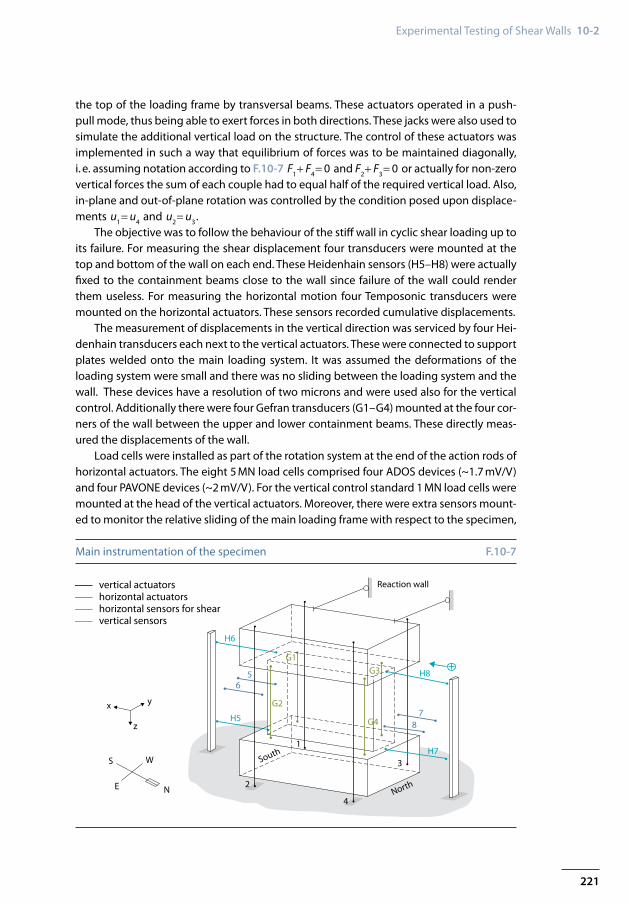
vertical actuatorshorizontal actuatorshorizontal sensors for shearvertical sensors
Main instrumentation of the specimen F.10-7
the top of the loading frame by transversal beams. These actuators operated in a push-pull mode, thus being able to exert forces in both directions. These jacks were also used to simulate the additional vertical load on the structure. The control of these actuators was implemented in such a way that equilibrium of forces was to be maintained diagonally, i. e. assuming notation according to F.10-7 F1+ F4=0 and F2+ F3=0 or actually for non-zero vertical forces the sum of each couple had to equal half of the required vertical load. Also, in-plane and out-of-plane rotation was controlled by the condition posed upon displace-ments u1=u4 and u2=u3.
The objective was to follow the behaviour of the stiff wall in cyclic shear loading up to its failure. For measuring the shear displacement four transducers were mounted at the top and bottom of the wall on each end. These Heidenhain sensors (H5–H8) were actually fixed to the containment beams close to the wall since failure of the wall could render them useless. For measuring the horizontal motion four Temposonic transducers were mounted on the horizontal actuators. These sensors recorded cumulative displacements.
The measurement of displacements in the vertical direction was serviced by four Hei-denhain transducers each next to the vertical actuators. These were connected to support plates welded onto the main loading system. It was assumed the deformations of the loading system were small and there was no sliding between the loading system and the wall. These devices have a resolution of two microns and were used also for the vertical control. Additionally there were four Gefran transducers (G1–G4) mounted at the four cor-ners of the wall between the upper and lower containment beams. These directly meas-ured the displacements of the wall.
Load cells were installed as part of the rotation system at the end of the action rods of horizontal actuators. The eight 5 MN load cells comprised four ADOS devices (~1.7 mV/V) and four PAVONE devices (~2 mV/V). For the vertical control standard 1 MN load cells were mounted at the head of the vertical actuators. Moreover, there were extra sensors mount-ed to monitor the relative sliding of the main loading frame with respect to the specimen,
222
10 Testing of Stiff Shear Walls
Wall 4 Wall 5 Wall 1 Wall 2
0.5 MN/2c 11/07/2012 0.5 MN/9c 25/05/2012 0.5 MN/2c 02/10/2012 0.5 MN/2c 20/11/2012
0.5 MN/7c 12/07/2012 1.0 MN/2c 0.5 MN/7c 04/10/2012 0.5 MN/7c 22/11/2012
0.5 MN/1c 2.0 MN/2c 05/06/2012 0.5 MN/1c 0.5 MN/1c
1.0 MN/2c 3.0 MN/2c 7.0 MN/2c 08/10/2012 7.0 MN/2c 23/11/2012
2.0 MN/2c 16/07/2012 4.0 MN/2c 4.0 MN/2c 4.0 MN/2c
3.0 MN/2c 5.0 MN/2c 06/06/2012 3.0 MN/2c 3.0 MN/2c 26/11/2012
4.0 MN/2c 6.0 MN/2c 6.0 MN/2c 08/10/2012* 6.0 MN/2c
5.0 MN/2c 17/07/2012 6.5 MN/1c 07/06/2012 5.0 MN/4c 5.0 MN/2c 27/11/2012
6.0 MN/2c 7.0 MN/2c 08/06/2012 5.5 MN/1/2c 09/10/2012 5.5 MN/2c
6.5 MN/2c 18/07/2012 7.5 MN/2c –5.5 MN/0.5c 10/10/2012 6.0 MN/2c
7.0 MN/2c 24/07/2012 8.0 MN/1c 11/06/2012 6.0 MN/2c 6.5 MN/2c 28/11/2012
7.5 MN/2c Final cycle 12/06/2012 6.5 MN/2c 10/10/2012* 7.0 MN/2c
8.0 MN/2c 7.0 MN/2c 7.5 MN/2c 29/11/2012
Final cycle 26/07/2012 7.5 MN/2c 11/10/2012 1.0 MN/2c 04/12/2012
8.0 MN/2c 8.0 MN/2c
8.0 MN/1/2c 12/10/2012 Final cycle 05/12/2012
Final cycle
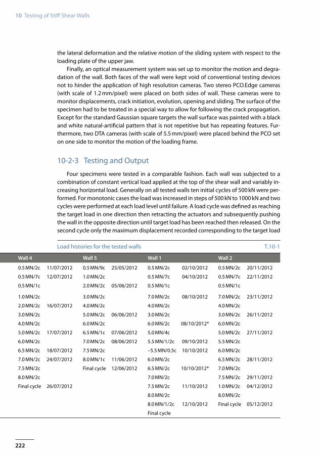
Load histories for the tested walls T.10-1
the lateral deformation and the relative motion of the sliding system with respect to the loading plate of the upper jaw.
Finally, an optical measurement system was set up to monitor the motion and degra-dation of the wall. Both faces of the wall were kept void of conventional testing devices not to hinder the application of high resolution cameras. Two stereo PCO.Edge cameras (with scale of 1.2 mm/pixel) were placed on both sides of wall. These cameras were to monitor displacements, crack initiation, evolution, opening and sliding. The surface of the specimen had to be treated in a special way to allow for following the crack propagation. Except for the standard Gaussian square targets the wall surface was painted with a black and white natural-artificial pattern that is not repetitive but has repeating features. Fur-thermore, two DTA cameras (with scale of 5.5 mm/pixel) were placed behind the PCO set on one side to monitor the motion of the loading frame.
10-2-3 Testing and Output
Four specimens were tested in a comparable fashion. Each wall was subjected to a combination of constant vertical load applied at the top of the shear wall and variably in-creasing horizontal load. Generally on all tested walls ten initial cycles of 500 kN were per-formed. For monotonic cases the load was increased in steps of 500 kN to 1000 kN and two cycles were performed at each load level until failure. A load cycle was defined as reaching the target load in one direction then retracting the actuators and subsequently pushing the wall in the opposite direction until target load has been reached then released. On the second cycle only the maximum displacement recorded corresponding to the target load
223
Experimental Testing of Shear Walls 10-2
40302010
0
Tota
l she
ardi
spla
cem
ent [
mm
]
−10−20−30
15
10
0 2,000 4,000 6,000 8,000 10,000Sample
12,000 14,000 16,000 20,00018,000
Vert
ical
disp
lace
men
t [m
m]
1st crack Steel yield
5
0
10,0008,0006,0004,0002,000
0
Hor
izon
tal l
oad
[kN
]
−4,000−2,000
−6,000−8,000
Collapse+ Collapse−
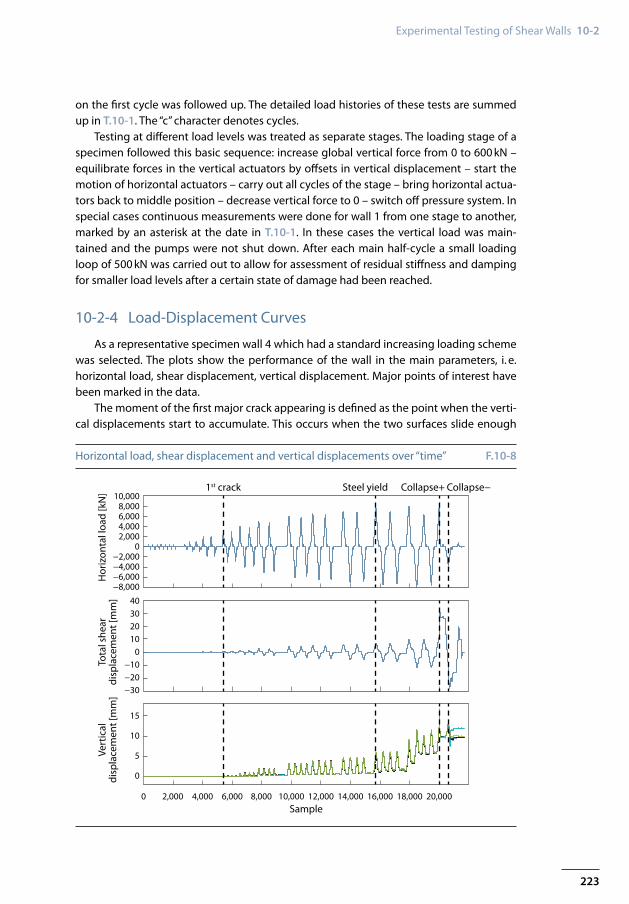
Horizontal load, shear displacement and vertical displacements over “time” F.10-8
on the first cycle was followed up. The detailed load histories of these tests are summed up in T.10-1. The “c” character denotes cycles.
Testing at different load levels was treated as separate stages. The loading stage of a specimen followed this basic sequence: increase global vertical force from 0 to 600 kN – equilibrate forces in the vertical actuators by offsets in vertical displacement – start the motion of horizontal actuators – carry out all cycles of the stage – bring horizontal actua-tors back to middle position – decrease vertical force to 0 – switch off pressure system. In special cases continuous measurements were done for wall 1 from one stage to another, marked by an asterisk at the date in T.10-1. In these cases the vertical load was main-tained and the pumps were not shut down. After each main half-cycle a small loading loop of 500 kN was carried out to allow for assessment of residual stiffness and damping for smaller load levels after a certain state of damage had been reached.
10-2-4 Load-Displacement Curves
As a representative specimen wall 4 which had a standard increasing loading scheme was selected. The plots show the performance of the wall in the main parameters, i. e. horizontal load, shear displacement, vertical displacement. Major points of interest have been marked in the data.
The moment of the first major crack appearing is defined as the point when the verti-cal displacements start to accumulate. This occurs when the two surfaces slide enough
224
10 Testing of Stiff Shear Walls
−30 −25 −20 −15 −10 −5 0 5
Collapse −
1st crack
Collapse +Steel yield
10 15 20 25 30 35 40
−7,000−6,000−5,000−4,000−3,000−2,000−1,000
1,0000
2,0003,0004,0005,0006,0007,0008,0009,000
10,000
−8,000
Displacement [mm]
Load
[kN
]
−30 −25
−7,000−6,000−5,000−4,000−3,000−2,000−1,000
01,0002,0003,0004,0005,0006,0007,0008,0009,000
10,000
−8,000−20 −15 −10 −5 0 5
Displacement [mm]
Collapse −
1st crack
Collapse +Steel yield
Load
[kN
]
10 15 20 25 30 35 40
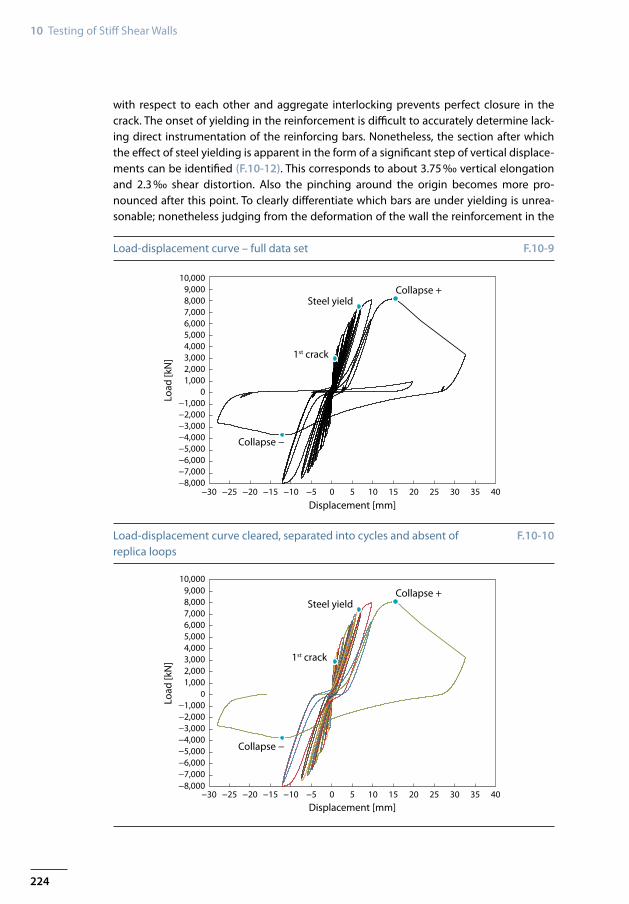
Load-displacement curve – full data set
Load-displacement curve cleared, separated into cycles and absent of replica loops
F.10-9
F.10-10
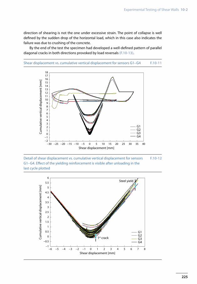
with respect to each other and aggregate interlocking prevents perfect closure in the crack. The onset of yielding in the reinforcement is difficult to accurately determine lack-ing direct instrumentation of the reinforcing bars. Nonetheless, the section after which the effect of steel yielding is apparent in the form of a significant step of vertical displace-ments can be identified (F.10-12). This corresponds to about 3.75 ‰ vertical elongation and 2.3 ‰ shear distortion. Also the pinching around the origin becomes more pro-nounced after this point. To clearly differentiate which bars are under yielding is unrea-sonable; nonetheless judging from the deformation of the wall the reinforcement in the
225
Experimental Testing of Shear Walls 10-2
−30 −25
−10123456789
101112131415161718
−2−20 −15 −10 −5 0 5
Shear displacement [mm]
G1G2G3G4
Cum
ulat
ive
vert
ical
dis
plac
emen
t [m
m]
10 15 20 25 30 35 40
1st crack
Steel yield
−6 −5
−0.5
0
0.5
1
1.5
2
2.5
3
3.5
4
4.5
5
5.5
6
−1−4 −3 −2 −1 0 1
Shear displacement [mm]
G1G2G3G4
Cum
ulat
ive
vert
ical
dis
plac
emen
t [m
m]
2 3 4 5 6 7 8
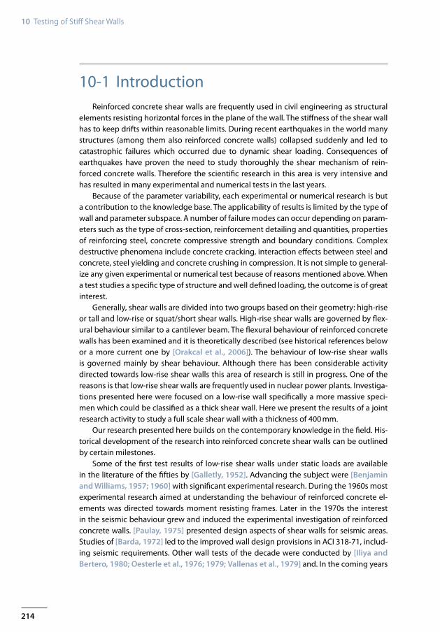
Shear displacement vs. cumulative vertical displacement for sensors G1–G4
Detail of shear displacement vs. cumulative vertical displacement for sensors G1–G4. Effect of the yielding reinforcement is visible after unloading in the last cycle plotted
F.10-11
F.10-12
direction of shearing is not the one under excessive strain. The point of collapse is well defined by the sudden drop of the horizontal load, which in this case also indicates the failure was due to crushing of the concrete.
By the end of the test the specimen had developed a well-defined pattern of parallel diagonal cracks in both directions provoked by load reversals (F.10-13).

226
10 Testing of Stiff Shear Walls
200
100200300400500600700800900
400 600 800 1000 1200 1400 1600 20001800 2200200
100200300400500600700800900
400 600 800 1000 1200 1400 1600 20001800 2200
Crack pattern at the end of the test of wall 2 (above). Vertical displacements from the optical system in the penultimate cycle in one direction and the ter-minal cycle in the opposite direction (below, courtesy of P. Capéran, ELSA, JRC)
F.10-13
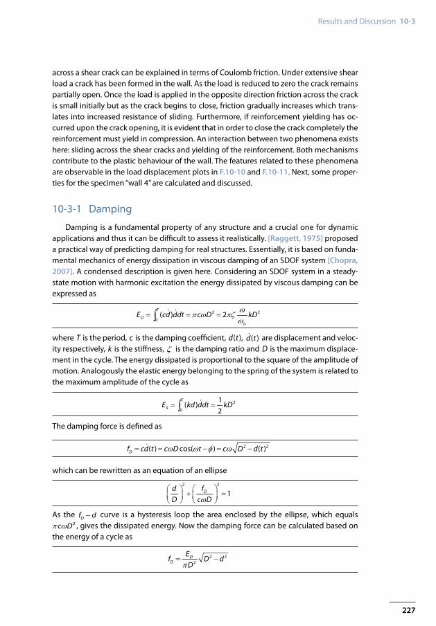
10-3 Results and DiscussionThe behaviour of a reinforced concrete shear wall cannot be separated into distinct
linear and non-linear regions because concrete has an inherently plastic behaviour. Al-though steel has a defined yield point, concrete is non-linear from initial loading and so the specimen as a whole shows a composite behaviour. The hysteresis presented in the previous section shows well the cyclic strength degradation as the second cycle on a dam-aged specimen does not reach the set load level at an equal horizontal displacement, which was the controlled variable. Progressive degrading phenomena occur, starting with concrete cracking, trough reinforcement yielding until the specimen fails by concrete crushing in the middle region of the wall. According to damage mechanics the behaviour of the shear wall specimen can be characterized as unilateral. During the cyclic loading of the wall to specific directions of the shearing two distinctive sets of shear cracks form in the wall (F.10-13). When the shear force changes sign one set of cracks tends to close and its presence has a reduced effect in the wall behaviour while the other set of cracks tends to open and becomes the dominant stiffness reduction phenomenon. During opening and closing of existing cracks the reinforcement in the disturbed areas is activated.
In the load-displacement curves of the test (F.10-10) a pinching around the origin can be seen. The phenomenon of pinching is due to sliding between the already cracked sur-faces of concrete before they come in full contact. This can be observed in the hysteresis curves where the sign of the shear force changes upon load reversal. This action of sliding
227
Results and Discussion 10-3
across a shear crack can be explained in terms of Coulomb friction. Under extensive shear load a crack has been formed in the wall. As the load is reduced to zero the crack remains partially open. Once the load is applied in the opposite direction friction across the crack is small initially but as the crack begins to close, friction gradually increases which trans-lates into increased resistance of sliding. Furthermore, if reinforcement yielding has oc-curred upon the crack opening, it is evident that in order to close the crack completely the reinforcement must yield in compression. An interaction between two phenomena exists here: sliding across the shear cracks and yielding of the reinforcement. Both mechanisms contribute to the plastic behaviour of the wall. The features related to these phenomena are observable in the load displacement plots in F.10-10 and F.10-11. Next, some proper-ties for the specimen “wall 4” are calculated and discussed.
10-3-1 Damping
Damping is a fundamental property of any structure and a crucial one for dynamic applications and thus it can be difficult to assess it realistically. [Raggett, 1975] proposed a practical way of predicting damping for real structures. Essentially, it is based on funda-mental mechanics of energy dissipation in viscous damping of an SDOF system [Chopra, 2007]. A condensed description is given here. Considering an SDOF system in a steady-state motion with harmonic excitation the energy dissipated by viscous damping can be expressed as
2 2
0( ) 2
T
Dn
E cd ddt c D kDωπ ω πζω
= = =∫
where T is the period, c is the damping coefficient, d(t), ( )d t are displacement and veloc-ity respectively, k is the stiffness, ζ is the damping ratio and D is the maximum displace-ment in the cycle. The energy dissipated is proportional to the square of the amplitude of motion. Analogously the elastic energy belonging to the spring of the system is related to the maximum amplitude of the cycle as
= =∫
2
0
1( )
2
T
SE kd ddt kD
The damping force is defined as
2 2( ) cos( ) ( )Df cd t c D t c D d tω ω φ ω= = - = -
which can be rewritten as an equation of an ellipse
2 2
1Dd fD c Dω
+ =
As the Df d- curve is a hysteresis loop the area enclosed by the ellipse, which equals 2c Dπ ω , gives the dissipated energy. Now the damping force can be calculated based on
the energy of a cycle as
2 22
DD
Ef D d
Dπ= -
228
10 Testing of Stiff Shear Walls
1 2 3 4 5 6 7 8 9 10 11 12 13
Cycle number
Ener
gy d
issi
pate
d pe
r cyc
le [k
J]
14 15 16 17 18 19 20 21 22 23 24 25 26 27 28
50
45
40
35
30
25
20
15
10
5
0
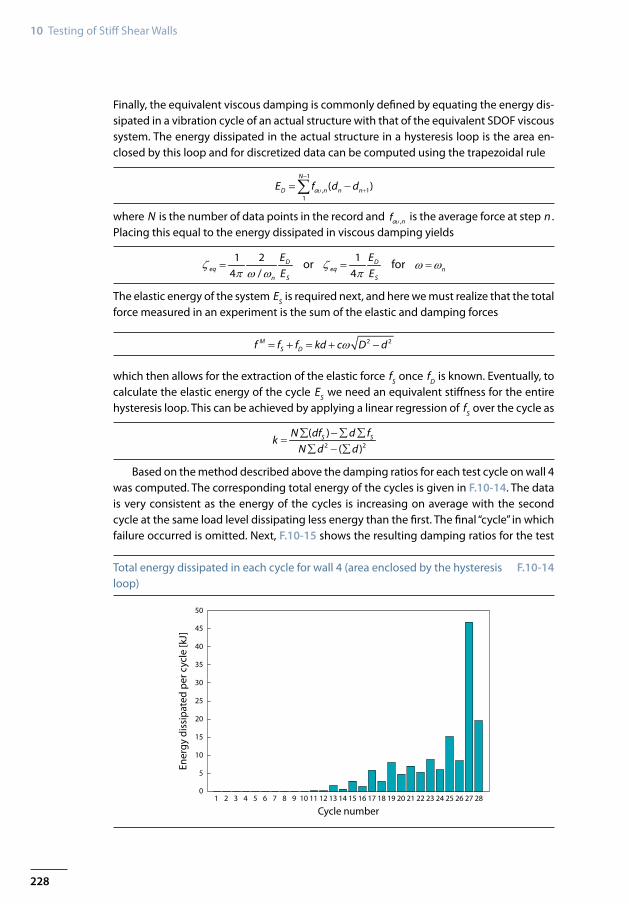
Total energy dissipated in each cycle for wall 4 (area enclosed by the hysteresis loop)
F.10-14
Finally, the equivalent viscous damping is commonly defined by equating the energy dis-sipated in a vibration cycle of an actual structure with that of the equivalent SDOF viscous system. The energy dissipated in the actual structure in a hysteresis loop is the area en-closed by this loop and for discretized data can be computed using the trapezoidal rule
1
, 11
( )N
D a n n nE f d dυ
-
+= -∑
where N is the number of data points in the record and ,a nf υ is the average force at step n . Placing this equal to the energy dissipated in viscous damping yields
1 24 /
Deq
n S
EE
ζπ ω ω
= or 14
Deq
S
EE
ζπ
= for nω ω=
The elastic energy of the system ES is required next, and here we must realize that the total force measured in an experiment is the sum of the elastic and damping forces
2 2MS Df f f kd c D dω= + = + -
which then allows for the extraction of the elastic force fS once fD is known. Eventually, to calculate the elastic energy of the cycle ES we need an equivalent stiffness for the entire hysteresis loop. This can be achieved by applying a linear regression of fS over the cycle as
2 2
( )( )
S SN df d fk
N d d∑ -∑ ∑
=∑ - ∑
Based on the method described above the damping ratios for each test cycle on wall 4 was computed. The corresponding total energy of the cycles is given in F.10-14. The data is very consistent as the energy of the cycles is increasing on average with the second cycle at the same load level dissipating less energy than the first. The final “cycle” in which failure occurred is omitted. Next, F.10-15 shows the resulting damping ratios for the test
229
Results and Discussion 10-3
1 2 3 4 5 6 7 8 9 10 11 12 13
Cycle number
Dam
ping
ratio
[%]
14 15 16 17 18 19 20 21 22 23 24 25 26 27 28
9
8
7
6
5
43.5
2.5
1.5
0.5
8.5
7.5
6.5
5.5
4.5
3
2
1
0
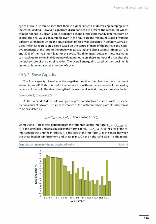
Damping estimate for the test cycles of wall 4 F.10-15
cycles of wall 4. It can be seen that there is a general trend of decreasing damping with increased loading. However significant discrepancies are present the reason for which, though not entirely clear, is quite probably a shape of the cycle starkly different from an ellipse. The final values of damping given in the figure are the minimum values of various different estimations where the equivalent stiffness k was calculated in different ways. Be-sides the linear regression, a slope based on the centre of mass of the positive and nega-tive segments of the loop to the origin was calculated and also a secant stiffness at 10 % and 50 % of the maximum load for the cycle. The differences between these estimates can reach up to 3 % in final damping values, nonetheless these methods did not alter the general picture of the damping ratios. The overall energy dissipated by the specimen is limited as it depends on the number of cycles.
10-3-2 Shear Capacity
The final capacity of wall 4 in the negative direction, the direction the experiment started in, was 8117 kN. It is useful to compare this with normative values of the bearing capacity of the wall. The shear strength of the wall is calculated using various standards.
Eurocode 2, Clause 6.2.5
As the Eurocode 8 does not have specific provisions for low-rise shear walls the shear-friction concept is taken. The shear resistance of the wall connection plate at its bottom is to be calculated as
( sin cos ) 0.5Rdi ctd n yd cdcf f fυ µσ ρ µ α α ν= + + + ≤
where c and µ are factors depending on the roughness of the interface, ,0.05 /ctd ct ctd cf fα γ= ,
nα is the stress per unit area caused by the normal force, /s iA Aρ = , As is the area of the re-inforcement crossing the interface, Ai is the area of the interface, α is the angle between the shear friction reinforcement and shear plane. On the right-hand side ν is the reduc-
230
10 Testing of Stiff Shear Walls
tion factor for concrete cracked in shear and fcd is the design compressive strength of con-crete. According to the code only the first term is factored with the material safety factor for concrete while the second term is taken at full value and the third term constituting the reinforcement is factored with sγ . The shear capacity of the wall according to the EC2 equation is 5655 kN, (relegating safety factors Vr equals 5805 kN).
US code ACI 349, Clause 11.7
Design provisions are given in ACI 318 for regular structures and ACI 349 for nuclear structures. This approach may be applied when shear transfer across a given plane is war-ranted. The nominal shear force is taken as
( sin cos )n vf yV A f µ α α= +
where µ is the coefficient of friction, Avf is the area of reinforcement in the shear plane, fy is the yield strength of the reinforcement and α is the angle between reinforcement resisting shear and the shear plane. The value of Vn is limited between 0.2fc Ac and 5.5 Ac . In this code the safety factor is not material but rather behavioural. For shear phenomena the factor is φ = 0.75. Although the above equation does include a term for normal pres-sure the ACI 349 permits to add it to Avf fy when calculating the required Avf . The shear capacity of the wall including the effect of the axial force and applying the given safety factor is 4087 kN, while without the safety factor capacity equals to 5450 kN.
US code ACI 349, Clause 11.10
A special provision is given for shear transfer in case of walls. In term of shear stresses the capacity is given as follows
0.75(0.216 0.2 0.8 )f c u t yv f fσ ρ= + +
where fc is the concrete strength in compression, uσ is the normal stress pre-unit area and
tρ is the ratio of reinforcement resisting shear. Based on this formula the wall strength is evaluated at 4340 kN.
US code ACI 349, Clause 21.7.4
A special clause is given for low-rise shear walls with aspect ratio / 1.5H L ≤ . The fac-tored capacity per unit area is given by
0.75(0.25 )f c t yv f fρ= +
where tρ is the ratio of reinforcement resisting shear. The wall capacity according to this equation is 5137 kN.
A commonly used approach for checking the shear capacity of walls applied in many cases over the years is Hirosawa’s formula which is presented here
231
Results and Discussion 10-3
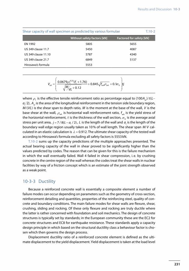
Without safety factors [kN] Factored for safety [kN]
EN 1992 5805 5655
US 349 clause 11.7 5450 4087
US 349 clause 11.10 5787 4340
US 349 clause 21.7 6849 5137
Hirosawa’s formula 5553
Shear capacity of wall specimen as predicted by various formulae T.10-2
0.23
0
0.0679 ( 1.76)0.845 0.1
0.12t c
ult wh wh
fV f tj
MVL
ρ ρ σ
+ = + + +
where tρ is the effective tensile reinforcement ratio as percentage equal to (100Ast )/t(L-al /2), Ast is the area of the longitudinal reinforcement in the tension side boundary region, M/(VL) is the shear span to depth ratio, M is the moment at the base of the wall, V is the base shear at the wall, whρ is horizontal wall reinforcement ratio, fwh is the yield stress of the horizontal reinforcement, t is the thickness of the wall section, 0σ is the average axial stress per unit area, 7 / 8( / 2)lj L a= - , L is the length of the wall and al is the length of the boundary wall edge region usually taken as 10 % of wall length. The shear span M/V cal-culated in an elastic calculation is λ = 0.912. The ultimate shear capacity of the tested wall according to Hirosawa’s formula excluding all safety factors is 5553 kN.
T.10-2 sums up the capacity predictions of the multiple approaches presented. The actual bearing capacity of the wall in shear proved to be significantly higher than the values predicted by codes. The reason that can be given for this is the failure mechanism in which the wall eventually failed. Wall 4 failed in shear compression, i. e. by crushing concrete in the centre region of the wall whereas the codes treat the shear walls in nuclear facilities by way of a friction concept which is an estimate of the joint strength observed as a weak point.
10-3-3 Ductility
Because a reinforced concrete wall is essentially a composite element a number of failure modes can occur depending on parameters such as the geometry of cross-section, reinforcement detailing and quantities, properties of the reinforcing steel, quality of con-crete and boundary conditions. The main failure modes for shear walls are flexure, shear, crushing, sliding and rocking. Of these only flexure and rocking are truly ductile where the latter is rather concerned with foundation and soil mechanics. The design of concrete structures is typically set by standards; in the European community these are the EC2 for concrete structures and EC8 for earthquake resistance. These standards apply a capacity design principle in which based on the structural ductility class a behaviour factor is cho-sen which then governs the design process.
Displacement ductility ratio of a reinforced concrete element is defined as the ulti-mate displacement to the yield displacement. Yield displacement is taken at the load level
232
10 Testing of Stiff Shear Walls
Displacement [mm]
max in cycle 1max in cycle 2min in cycle 1min in cycle 2
Collapse
Actu
ator
forc
e [k
N]
10,000
−8,000−7,000−6,000−5,000−4,000−3,000−2,000−1,000
9,0008,0007,0006,0005,0004,0003,0002,0001,000
0−12 −8 −4 0 4 8 12 16 20
Steel yield
Crack initiation
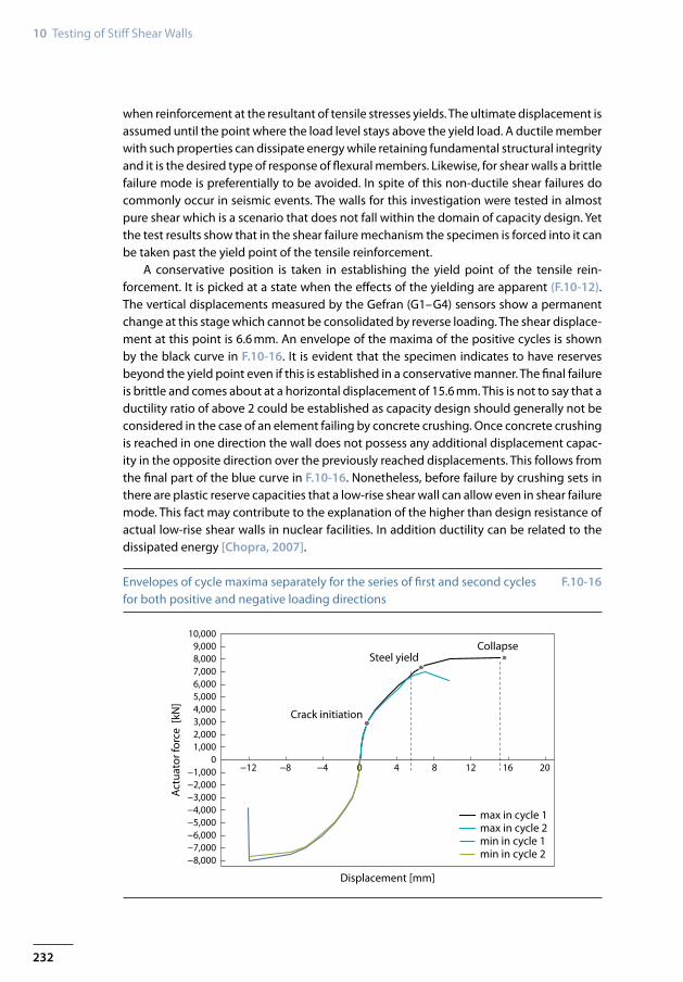
Envelopes of cycle maxima separately for the series of first and second cycles for both positive and negative loading directions
F.10-16
when reinforcement at the resultant of tensile stresses yields. The ultimate displacement is assumed until the point where the load level stays above the yield load. A ductile member with such properties can dissipate energy while retaining fundamental structural integrity and it is the desired type of response of flexural members. Likewise, for shear walls a brittle failure mode is preferentially to be avoided. In spite of this non-ductile shear failures do commonly occur in seismic events. The walls for this investigation were tested in almost pure shear which is a scenario that does not fall within the domain of capacity design. Yet the test results show that in the shear failure mechanism the specimen is forced into it can be taken past the yield point of the tensile reinforcement.
A conservative position is taken in establishing the yield point of the tensile rein-forcement. It is picked at a state when the effects of the yielding are apparent (F.10-12). The vertical displacements measured by the Gefran (G1–G4) sensors show a permanent change at this stage which cannot be consolidated by reverse loading. The shear displace-ment at this point is 6.6 mm. An envelope of the maxima of the positive cycles is shown by the black curve in F.10-16. It is evident that the specimen indicates to have reserves beyond the yield point even if this is established in a conservative manner. The final failure is brittle and comes about at a horizontal displacement of 15.6 mm. This is not to say that a ductility ratio of above 2 could be established as capacity design should generally not be considered in the case of an element failing by concrete crushing. Once concrete crushing is reached in one direction the wall does not possess any additional displacement capac-ity in the opposite direction over the previously reached displacements. This follows from the final part of the blue curve in F.10-16. Nonetheless, before failure by crushing sets in there are plastic reserve capacities that a low-rise shear wall can allow even in shear failure mode. This fact may contribute to the explanation of the higher than design resistance of actual low-rise shear walls in nuclear facilities. In addition ductility can be related to the dissipated energy [Chopra, 2007].
233
References 10
10-3-4 Summary
Strong short shear walls have been tested in a novel way where shearing was the dominant mode of behaviour all the way to failure. The shear wall had a thickness of 40 cm to closer represent a structural part existent in nuclear facilities. A special loading device was constructed allowing a symmetrical closed system loading. An elaborate displace-ment and rotation control was needed at the load transfer point. Additionally, the top of the specimen was held horizontal to promote shear behaviour. The quasi-static loading was administered in cycles of preconceived load levels. The unilateral response of the wall was monitored by a group of horizontal and vertical transducers. On the resulting load displacement curves features of degradation are identifiable. Wall 4 was selected for pri-mary data processing. The failure load in the initial loading direction was 8117 kN, which was due to concrete crushing in the middle of the wall. The experimental strength was compared to various design checks based on different codes. Reserves based on these comparisons ranged from 43 % to 98 %. It is well to be noted though, that the failure mechanisms in the case of the experiment versus the codes are not comparable. The data was further investigated and we looked at other characteristics like damping and ductility. A short shear wall failing in a brittle mode still shows remaining displacement capacities after the onset of yielding in the reinforcement. The damping estimates for the wall show discrepancies between cycles but are consistently higher than generally assumed for this type of structure in design.
ReferencesACI 318, 2011. Building Code Requirements for Reinforced Concrete. ACI Committee, Ameri-
can Concrete Institute, Michigan.Barda, F., 1972. Shear Strength of Low-Rise Walls with Boundary Elements. PhD dissertation,
Lehigh University.Benjamin, J. R. and Williams, H. A., 1957. The Behavior of One-Storey Reinforced Concrete
Shear Walls. Journal of the Structural Division, ASCE 83:1–49.Benjamin, J. R. and Williams, H. A., 1960. Reinforced Concrete Shear Walls Assemblies. Jour-
nal of the Structural Division, ASCE 86(8):1–32.Brun, M., Reynouard, J. M. and Jezequel, L., 2003. A Simple Shear Wall Model Taking into
Account Stiffness Degradation. Engineering Structures 25:1–9.Brun, M., Labbe, P., Betrand, D. and Courtois, A., 2011. Pseudo-Dynamic Tests on Low-
Shear Walls and Simplified Model Based on the Structural Frequency Drift. Engineering Structures 33:769–812.
Chopra, A. K., 2007. Dynamics of Structures. Prentice Hall, 3rd edition.Eurocode 8, 2010. Design Provisions for Earthquake Resistance of Structures, Part 1–3: Gen-
eral Rules – Specific Rules for Various Materials and Elements. CEN: European Committee for Standardization, Bruxelles.
Fouré, B., 1993. Un Programme Dèssais des Murs de Contreventement. In: Colloquium AFPS-SECED experimental methods in earthquake engineering and structural dynamics, Saint-Rémy-lés-Chevreuse, AFPS – Association Francaise du Genie Parasismique.
234
10 Testing of Stiff Shear Walls
Galletly, G. D., 1952. Behavior of Reinforced Concrete Shear Walls under Static Load. Depart-ment of Civil and Sanitary Engineering, MIT Cambridge, MA.
Greifenhagen, C. and Lestuzzi, P., 2005. Static Cyclic Test on Lightly Reinforced Concrete Shear Walls. Engineering Structures 27(11):1703–1712.
Iliya, R. and Bertero, V., 1980. Effects of Amount and Arrangement of Wall-Panel Reinforce-ment on Hysteretic Behavior of Reinforced Concrete Walls. Report No. UCB/EERC 80/04, Berkeley, University of California.
Lopes, M. S., 2001a. Experimental Shear-Dominated Response of RC Walls. Part I: Objectives, Methodology and Results. Engineering Structures 23:229–239.
Lopes, M. S., 2001b. Experimental Shear-Dominated Response of RC Walls. Part II: Discussion of Results and Design Implications. Engineering Structures 23:564–574.
Maier, J. and Thürlimann, B., 1985. Bruchversuche an Stahlbetonscheiben. IBK Bericht 8003-1 Zurich ETH.
Mo, Y. L. and Chan, J., 1996. Behavior of Reinforced-Concrete Shear Walls. Nuclear Engineer-ing and Design 166:55–68.
Oesterle, R., Fioratio, A., Johal, L., Carpenter, H. and Corley, W., 1976. Earthquake Resist-ant Structural Walls – Tests of Isolated Walls. PCA Construction Technology Laboratories.
Oesterle, R., Aristizabal-Ochoa, J., Fiorato, A., Russel, H. and Corley, W., 1979. Earthquake Resistant Structural Walls – Tests of Isolated Walls – Phase II. PCA Construction Technol-ogy Laboratories, Skokie (Illinois).
Orakcal, K., Massone, L. M. and Wallace, J. W., 2006. Analytical Modeling of Reinforced Con-crete Walls for Predicting Flexural and Coupled-Shear-Flexural Responses. PEER Report 2006/07 Pacific Earthquake Engineering Research Center, Berkley.
Paulay, T., 1975. Design Aspects of Shear Walls for Seismic Areas. Canadian Journal of Civil Engineering 2(3):321–344.
Raggett, J. D., 1975. Estimating Damping of Real Structures. ASCE Technical Publication 1823–1835.
Rothe, D., 1992. Untersuchungen zum nichtlinearen Verhalten von Stahlbetonwandscheiben unter Erdbebenbeanspruchung. VDI-Forschrittsberichte, Düsseldorf, VDI-Verlag, 4(117).
Vallenas, J., Bertero, V. and Popov, E., 1979. Hysteretic Behavior of Reinforced Concrete Structural Walls. Report no UCB/EERC-79/20, University of California, Berkeley.
Salonikios, T., Kappos, A., Tegos, A. and Penelis, G., 1999. Cyclic Load Behaviour of Low Slenderness Reinforced Concrete Walls: Design Basis and Test Results. ACI Structural Jour-nal 96(4):649–660.
Thomsona, E. D., Perdomob, M. E., Picón, R., Maranteb, M. E. and Flórez-López, J., 2009. Simplified Model for Damage in Squat RC Shear Walls. Engineering Structures 31:2215–2223.
Wallace, J., 1995. Seismic Design of RC Structural Walls. Part I: New Code Format. Journal of Structural Engineering 121(1):75–87.