Embed Size (px)
Citation preview
Colorado Department of Transportation Page 279
Chapter 10 - Roadway Modeling
Roadway Modeling is the process of creating a 3D design surface or surfaces of your proposed roadway project. The modeling process utilizes the roadway typical sections discussed in the last chapter and applies these sections to a corridor (a path representing the location of your project). As the typical sections are “pushed” along this path, end condition components “tie-in” to the existing surface (or any other targets you specify) to create your cut and fill sideslopes. Template points are then connected to created 3D longitudinal breakline features along the corridor. Triangulation creates planar surfaces between breakline feature points from which elevations can be interpolated. The resulting 3D surface is known as the proposed model. InRoads Roadway Designer is the interface between engineering design data and the proposed surface model.
Chapter Objectives:
To understand how roadway modeling is accomplished using CDOT standard design criteria and InRoads XM.
To learn how to create a preliminary model of your project.
To further define your model by introducing right and left turn lanes, ramps, acceleration lanes, etc.
To learn how CDOT establishes superelevation design criteria to maintain vehicle stability at the designed speed for each curve on your project.
To learn how to vary pavement or subgrade depths over a specified range.
To learn different methods of editing your design model to correct sideslope problems or fit your design to real world conditions.
To learn how to create a 3D design surface of your project.
Page 280 Colorado Department of Transportation
Chapter 10 - Roadway Modeling A Practical Guide for Using InRoads XM
Roadway Designer
Roadway Designer is a new interactive approach to modeling with templates in InRoads, allowing you to see the results of your the results of your design simultaneously in plan, profile, and cross section before creating your proposed surface.
Roadway Designer is a tool used to:
Specify the project path (horizontal and vertical alignments or surface features)
Identify the templates to be used for modeling
Control template locations along the project path and define transitions
Define paths for points that don’t parallel the centerline, such as tapers
Define superelevation
Create the design surface – a 3D model of the proposed design
Section Objectives:
♦ To utilize Roadway Designer as a tool to input design data for modeling purposes.
♦ To understand the full functionality of Roadway Designer and its tools.
♦ To use and interpret plan, profile, section and superelevation diagram information in Roadway Designer’s Standard and Superelevation modes.
♦ To understand what data is needed to before using Roadway Designer for modeling.
♦ To understand what data is created by Roadway Designer and where it is stored.
♦ To learn what commands are available on Roadway Designer’s menu.
♦ To learn how to process Roadway Designer data to create a preliminary view of your design in plan, profile and cross section.
♦ To learn how to create a corridor.
♦ To learn when and how to add template drops to your corridor.
♦ To edit template drops and synchronize templates drops with the template library changes.
♦ To understand how Point Controls work and when to use them.
♦ To add point controls to your design to minimize template drops.
♦ To understand the CDOT process of adding superelevation to your roadway.
♦ To utilize the Superelevation Table Wizard to calculate the initial superelevation.
♦ To edit the results of the Superelevation Table Wizard to meet your project’s design criteria.
♦ To understand when and how to use Secondary Alignments.
Introduction to Roadway Designer
Roadway Designer Prerequisites
Before running Roadway Designer, you must first have:
Colorado Department of Transportation Page 281
A Practical Guide for Using InRoads XM Chapter 10 - Roadway Modeling
A horizontal and vertical alignment that defines your proposed location (the project centerline and profile grade). You can also use a surface feature to define the path.
An existing surface or surfaces. These provide the targets for your end conditions. If your target(s) are not surfaces, these targets must also be loaded.
One or more templates to define the typical section of the proposed design.
Starting Roadway Designer
From the InRoads Explorer menu, select Modeler > Roadway Designer to open the Roadway Designer dialog box.
Working Modes
In the Roadway Designer dialog box, you can see the results of your model run and work with your data using two different two modes: Standard and Superelevation.
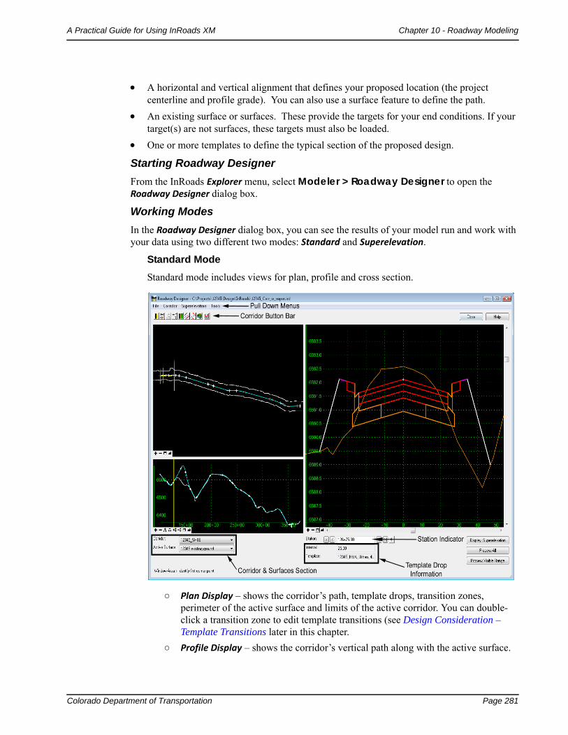
Standard Mode
Standard mode includes views for plan, profile and cross section.
○ Plan Display – shows the corridor’s path, template drops, transition zones, perimeter of the active surface and limits of the active corridor. You can double-click a transition zone to edit template transitions (see Design Consideration – Template Transitions later in this chapter.
○ Profile Display – shows the corridor’s vertical path along with the active surface.
Page 282 Colorado Department of Transportation
Chapter 10 - Roadway Modeling A Practical Guide for Using InRoads XM
○ Cross Section Display – shows the cross section surfaces and components at the current station. You can hover over a point or component to get additional information (name, offset, elevation, style, constraints, material, slope, width, etc.) Double-clicking the cross section display activates the Edit Station command, which allows you to interactively edit any station along the corridor. Points and components can be edited at the single station to correct any problems along the alignment (see Modifying Single Station Template Drops in this chapter).
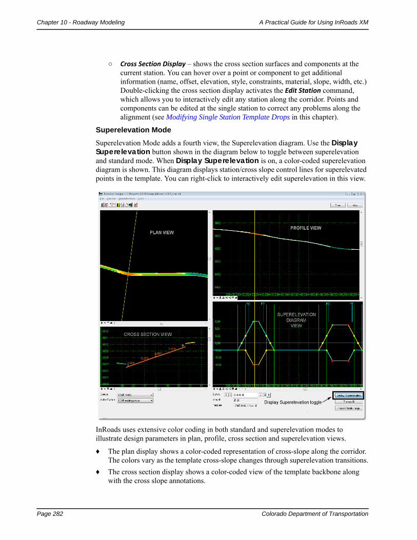
Superelevation Mode
Superelevation Mode adds a fourth view, the Superelevation diagram. Use the Display Superelevation button shown in the diagram below to toggle between superelevation and standard mode. When Display Superelevation is on, a color-coded superelevation diagram is shown. This diagram displays station/cross slope control lines for superelevated points in the template. You can right-click to interactively edit superelevation in this view.
InRoads uses extensive color coding in both standard and superelevation modes to illustrate design parameters in plan, profile, cross section and superelevation views.
♦ The plan display shows a color-coded representation of cross-slope along the corridor. The colors vary as the template cross-slope changes through superelevation transitions.
♦ The cross section display shows a color-coded view of the template backbone along with the cross slope annotations.
Colorado Department of Transportation Page 283
A Practical Guide for Using InRoads XM Chapter 10 - Roadway Modeling
♦ The profile display shows a color-coded view of all points on the template backbone. You can right-click to control which points are displayed, which allows for interactive viewing of superelevation transitions in vertical sag curves.
For more information on superelevation and color coding, see the Superelevation section in this chapter.
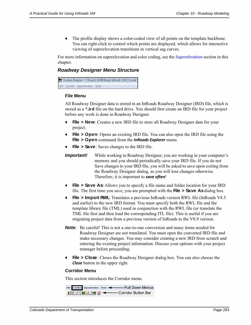
Roadway Designer Menu Structure
File Menu
All Roadway Designer data is stored in an InRoads Roadway Designer (IRD) file, which is stored as a *.ird file on the hard drive. You should first create an IRD file for your project before any work is done in Roadway Designer.
♦ File > New: Creates a new IRD file to store all Roadway Designer data for your project.
♦ File > Open: Opens an existing IRD file. You can also open the IRD file using the File > Open command from the InRoads Explorer menu.
♦ File > Save: Saves changes to the IRD file.
Important! While working in Roadway Designer, you are working in your computer’s memory and you should periodically save your IRD file. If you do not Save changes to your IRD file, you will be asked to save upon exiting from the Roadway Designer dialog, as you will lose changes otherwise. Therefore, it is important to save often!
♦ File > Save As: Allows you to specify a file name and folder location for your IRD file. The first time you save, you are prompted with the File > Save As dialog box.
♦ File > Import RWL: Translates a previous InRoads version RWL file (InRoads V8.5 and earlier) to the new IRD format. You must specify both the RWL file and the template library file (TML) used in conjunction with the RWL file (or translate the TML file first and then load the corresponding ITL file). This is useful if you are migrating project data from a previous version of InRoads to the V8.9 version.
Note: Be careful! This is not a one-to-one conversion and many items needed for Roadway Designer are not translated. You must open the converted IRD file and make necessary changes. You may consider creating a new IRD from scratch and entering the existing project information. Discuss your options with your project manager before proceeding.
♦ File > Close: Closes the Roadway Designer dialog box. You can also choose the Close button in the upper right.
Corridor Menu
This section introduces the Corridor menu.
Page 284 Colorado Department of Transportation
Chapter 10 - Roadway Modeling A Practical Guide for Using InRoads XM
Note: All of the commands found on the Corridor pull-down menu can also be accessed on the Corridor button bar located directly below the pull-down menus.
The Corridor menu is used to setup the following data, which is then used in the modeling process:
♦ Corridor > Corridor Management: Creates a corridor – either a horizontal and vertical alignment or surface feature defining the “path” of your project.
♦ Corridor > Template Drops: Specifies a start/stop station range for applying the various templates along the corridor. The area along the corridor between different templates is know as the template transition zone.
♦ Corridor > Point Controls: Used to set up and manage horizontal and vertical controls for points in a template for widening lanes, introducing ramps, maintaining right-of-way, etc. Point controls are also used for superelevation controls.
♦ Corridor > End Condition Exceptions: Options for modifying end conditions (e.g. cut and fill sideslopes) along a station range without introducing additional template drops and editing template transitions. There are two different types of End Condition Exceptions:
○ Overrides – to replace the end condition on the right and/or left side
○ Transitions – to smooth out rapidly changing end conditions over a station range
♦ Corridor > Display References: Used to display alignments and surface features in the Roadway Designer plan and cross section views. Graphics cannot be referenced.
♦ Corridor > Secondary alignments: Used to specify alignments that 'kink' the template. The template is run perpendicular to the mainline until it reaches the secondary alignment, then it becomes perpendicular to it.
♦ Corridor > Key Stations: Similar to event points on an alignment, Key Stations are special stations where you want to drop a template and display a cross section (utility, culvert or railroad crossings, drive entrances, intersections, etc.). Unlike event points, which are stored in the ALG file, Key Stations are stored in the IRD file.
♦ Corridor > Create Surface: Creates a surface (DTM) or surfaces from the roadway design data. You can create a separate surface for each corridor, including subgrade surfaces, or you can create one merged surface by combining multiple corridors in the design.
Superelevation Menu
See the Superelevation section later in this Chapter.
Tools Menu
♦ Tools > Parametric Constraints: Used to override labeled point constraint values over a station range without requiring additional template drops. Parametric constraints are commonly used to vary such criteria as pavement thickness, sidewalk width and cross slopes over a station range in the corridor.
♦ Tools > Target Aliasing: Allows you to override the end condition target defined in the template and specify additional surfaces or corridors as targets in a prioritized order.
Colorado Department of Transportation Page 285
A Practical Guide for Using InRoads XM Chapter 10 - Roadway Modeling
♦ Tools > Curve Widening: Used in widening projects to add horizontal point controls to move points on curves further away from the centerline when widening lanes or edges.
♦ Tools > Vertical Gore Tool: Allows you to create surface features representing the min/max elevation range of a ramp’s vertical alignment to meet cross slope rollover and other design criteria. These features can be shown on the profile to help design gore area cross slopes and match them to the mainline and the ramp cross slopes.
♦ Tools > Design Input Report (ird file): Generates an XML report from your Roadway Designer setup data. After selecting this command, choose one of the style sheets (XSL files) from the Roadway folder in the Report Browser to format the report.
♦ Tools > Results Report: Generate XML reports of the roadway design results. After selecting this command, choose one of the style sheets (XSL files) from the Roadway folder in the Report Browser to format the report.
♦ Tools > Options: Used to set up additional processing and display options for Roadway Designer. This includes options for dropping templates at specified event points, displaying references and template transitions in plan view, and displaying cut and fill volumes in cross section view.
These concepts are explained in more detail later in this chapter. Additional information can be found by reviewing the topic Roadway Designer Overview in the InRoads Online Help.
Processing your data
Roadway Designer processes your templates along all specified stations of the corridor. Each view display (plan, profile and section) shows the results of your processed model at each station along the corridor. This allows you to preview the results of your model prior to creation of the 3D design surface.
Once you have set up your Roadway Designer data and saved the IRD file, you will need to process the data along the corridor in order to model the project. You can process Roadway Designer data using several different options including:
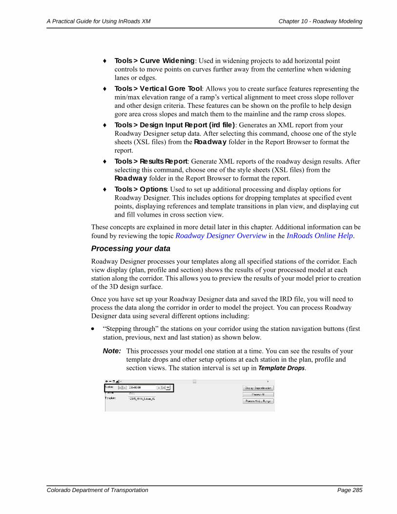
“Stepping through” the stations on your corridor using the station navigation buttons (first station, previous, next and last station) as shown below.
Note: This processes your model one station at a time. You can see the results of your template drops and other setup options at each station in the plan, profile and section views. The station interval is set up in Template Drops.
Page 286 Colorado Department of Transportation
Chapter 10 - Roadway Modeling A Practical Guide for Using InRoads XM
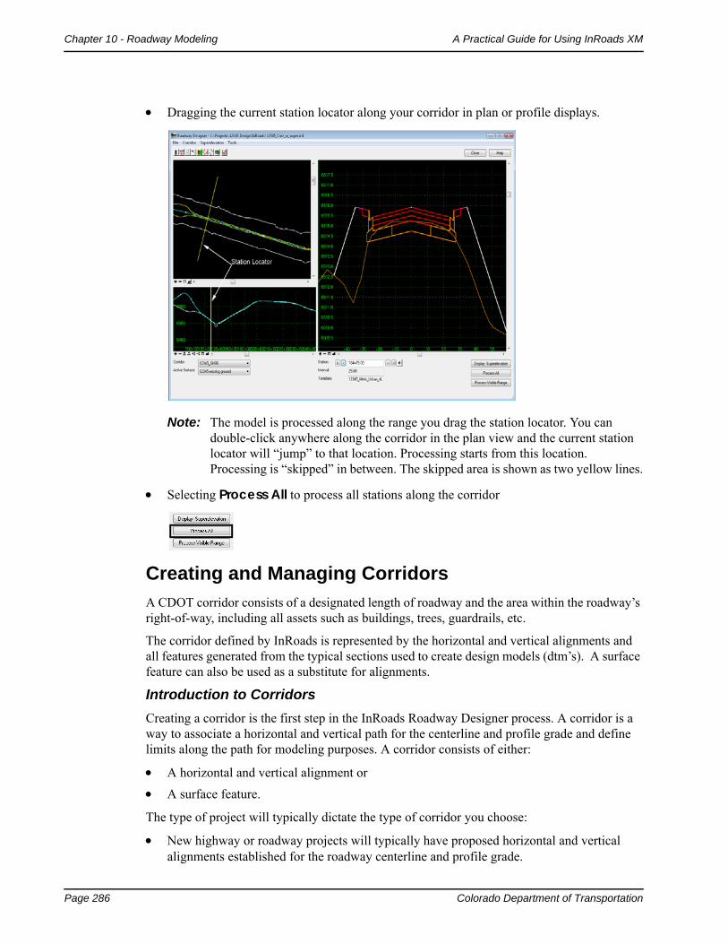
Dragging the current station locator along your corridor in plan or profile displays.
Note: The model is processed along the range you drag the station locator. You can double-click anywhere along the corridor in the plan view and the current station locator will “jump” to that location. Processing starts from this location. Processing is “skipped” in between. The skipped area is shown as two yellow lines.
Selecting Process All to process all stations along the corridor
Creating and Managing Corridors
A CDOT corridor consists of a designated length of roadway and the area within the roadway’s right-of-way, including all assets such as buildings, trees, guardrails, etc.
The corridor defined by InRoads is represented by the horizontal and vertical alignments and all features generated from the typical sections used to create design models (dtm’s). A surface feature can also be used as a substitute for alignments.
Introduction to Corridors
Creating a corridor is the first step in the InRoads Roadway Designer process. A corridor is a way to associate a horizontal and vertical path for the centerline and profile grade and define limits along the path for modeling purposes. A corridor consists of either:
A horizontal and vertical alignment or
A surface feature.
The type of project will typically dictate the type of corridor you choose:
New highway or roadway projects will typically have proposed horizontal and vertical alignments established for the roadway centerline and profile grade.
Colorado Department of Transportation Page 287
A Practical Guide for Using InRoads XM Chapter 10 - Roadway Modeling
If you’re modeling a ditch or other corridor based on a surface feature, use the surface feature option. For example, overlay projects may have a surface feature representing the existing centerline provided by Survey (however, this surface feature may also be imported into the geometry project as an alignment).
After designating the path, you assign a name for this path, which is known as the corridor. The corridor is the path along which you will drop templates to model the roadway. Your design can consist of one corridor or multiple corridors (e.g. a mainline and ramps). After the design is complete, you can create a separate surface for each corridor or one surface from multiple corridors.
All of the Roadway Designer data is saved with the corridor (template drops, point controls, superelevation, parametric constraints, etc.) The corridor is then saved to the IRD file.
Note: Before creating a corridor, you must have your geometry project loaded (or surface if you’re using a feature to define the corridor).
Creating Corridors
To create a corridor:
1. Select Modeler > Roadway Designer from the main InRoads menu.
2. From the Roadway Designer menu bar, select Corridor > Corridor Management or
<D> the Corridor Management icon from the button bar.
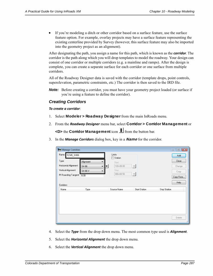
3. In the Manage Corridors dialog box, key in a Name for the corridor.
4. Select the Type from the drop down menu. The most common type used is Alignment.
5. Select the Horizontal Alignment the drop down menu.
6. Select the Vertical Alignment the drop down menu.
Page 288 Colorado Department of Transportation
Chapter 10 - Roadway Modeling A Practical Guide for Using InRoads XM
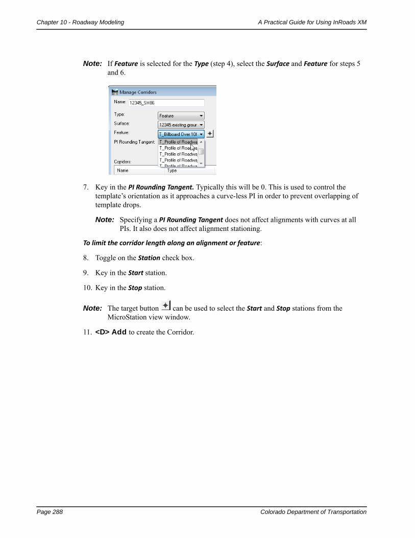
Note: If Feature is selected for the Type (step 4), select the Surface and Feature for steps 5 and 6.
7. Key in the PI Rounding Tangent. Typically this will be 0. This is used to control the template’s orientation as it approaches a curve-less PI in order to prevent overlapping of template drops.
Note: Specifying a PI Rounding Tangent does not affect alignments with curves at all PIs. It also does not affect alignment stationing.
To limit the corridor length along an alignment or feature:
8. Toggle on the Station check box.
9. Key in the Start station.
10. Key in the Stop station.
Note: The target button can be used to select the Start and Stop stations from the MicroStation view window.
11. <D> Add to create the Corridor.
Colorado Department of Transportation Page 289
A Practical Guide for Using InRoads XM Chapter 10 - Roadway Modeling
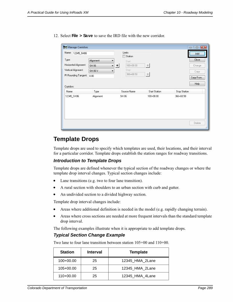
12. Select File > Save to save the IRD file with the new corridor.
Template Drops
Template drops are used to specify which templates are used, their locations, and their interval for a particular corridor. Template drops establish the station ranges for roadway transitions.
Introduction to Template Drops
Template drops are defined whenever the typical section of the roadway changes or where the template drop interval changes. Typical section changes include:
Lane transitions (e.g. two to four lane transition).
A rural section with shoulders to an urban section with curb and gutter.
An undivided section to a divided highway section.
Template drop interval changes include:
Areas where additional definition is needed in the model (e.g. rapidly changing terrain).
Areas where cross sections are needed at more frequent intervals than the standard template drop interval.
The following examples illustrate when it is appropriate to add template drops.
Typical Section Change Example
Two lane to four lane transition between station 105+00 and 110+00.
Station Interval Template
100+00.00 25 12345_HMA_2Lane
105+00.00 25 12345_HMA_2Lane
110+00.00 25 12345_HMA_4Lane
Page 290 Colorado Department of Transportation
Chapter 10 - Roadway Modeling A Practical Guide for Using InRoads XM
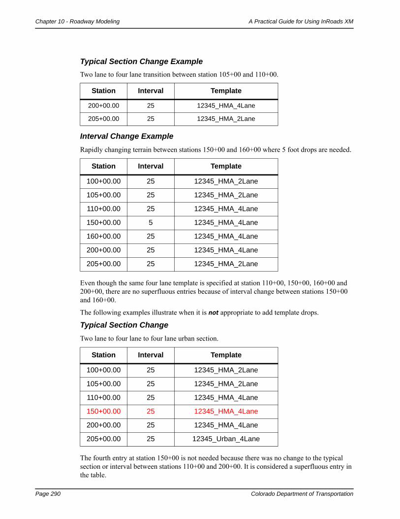
Interval Change Example
Rapidly changing terrain between stations 150+00 and 160+00 where 5 foot drops are needed.
Even though the same four lane template is specified at station 110+00, 150+00, 160+00 and 200+00, there are no superfluous entries because of interval change between stations 150+00 and 160+00.
The following examples illustrate when it is not appropriate to add template drops.
Typical Section Change
Two lane to four lane to four lane urban section.
The fourth entry at station 150+00 is not needed because there was no change to the typical section or interval between stations 110+00 and 200+00. It is considered a superfluous entry in the table.
200+00.00 25 12345_HMA_4Lane
205+00.00 25 12345_HMA_2Lane
Station Interval Template
100+00.00 25 12345_HMA_2Lane
105+00.00 25 12345_HMA_2Lane
110+00.00 25 12345_HMA_4Lane
150+00.00 5 12345_HMA_4Lane
160+00.00 25 12345_HMA_4Lane
200+00.00 25 12345_HMA_4Lane
205+00.00 25 12345_HMA_2Lane
Station Interval Template
100+00.00 25 12345_HMA_2Lane
105+00.00 25 12345_HMA_2Lane
110+00.00 25 12345_HMA_4Lane
150+00.00 25 12345_HMA_4Lane
200+00.00 25 12345_HMA_4Lane
205+00.00 25 12345_Urban_4Lane
Typical Section Change Example
Two lane to four lane transition between station 105+00 and 110+00.
Station Interval Template
Colorado Department of Transportation Page 291
A Practical Guide for Using InRoads XM Chapter 10 - Roadway Modeling
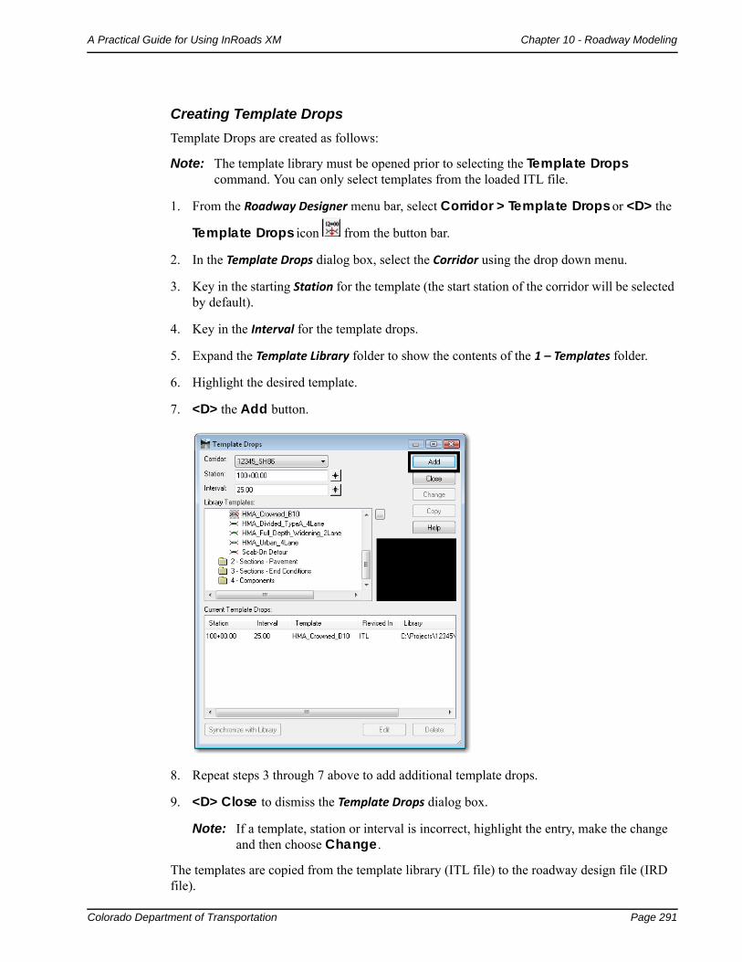
Creating Template Drops
Template Drops are created as follows:
Note: The template library must be opened prior to selecting the Template Drops command. You can only select templates from the loaded ITL file.
1. From the Roadway Designer menu bar, select Corridor > Template Drops or <D> the
Template Drops icon from the button bar.
2. In the Template Drops dialog box, select the Corridor using the drop down menu.
3. Key in the starting Station for the template (the start station of the corridor will be selected by default).
4. Key in the Interval for the template drops.
5. Expand the Template Library folder to show the contents of the 1 – Templates folder.
6. Highlight the desired template.
7. <D> the Add button.
8. Repeat steps 3 through 7 above to add additional template drops.
9. <D> Close to dismiss the Template Drops dialog box.
Note: If a template, station or interval is incorrect, highlight the entry, make the change and then choose Change.
The templates are copied from the template library (ITL file) to the roadway design file (IRD file).
Page 292 Colorado Department of Transportation
Chapter 10 - Roadway Modeling A Practical Guide for Using InRoads XM
Important! There is no dynamic link between templates in the library and template drops. Changes to templates in the roadway design file (IRD) will not affect templates in the template library (ITL). Likewise, changes to templates in the template library are not automatically updated in the roadway design file.
Therefore, the following are two options for editing templates that are used in the modeling process.
Editing a Template from the Template Drops Dialog Box
You may want to modify a standard template through an entire template drop station range without modifying the template in the template library. This allows you to use the standard template at another drop location without having to create a separate template in the library.
Note: This type of edit is usually the exception rather than the rule and is not often done. However, there may be special situations that warrant this type of edit, which is accomplished by editing the template directly from the Template Drops dialog box.
Important! These modifications will only be used for the station range highlighted. The changes in the template are not carried over to the template library. Instead, the modified template resides in the IRD file only.
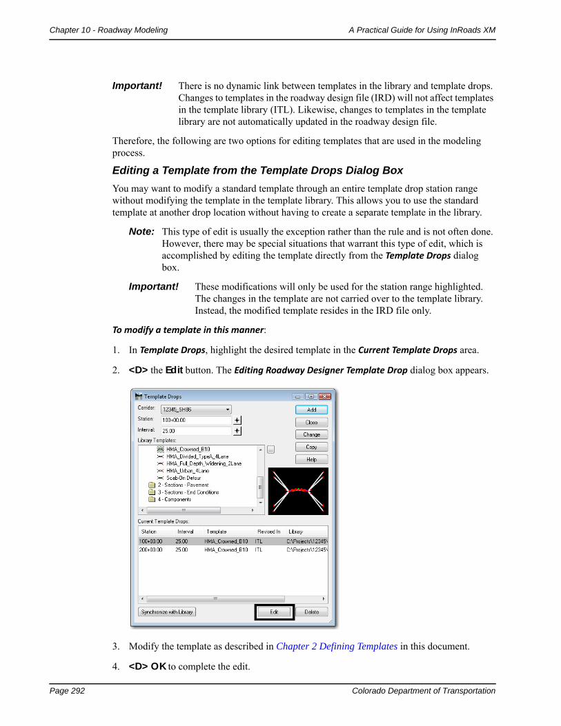
To modify a template in this manner:
1. In Template Drops, highlight the desired template in the Current Template Drops area.
2. <D> the Edit button. The Editing Roadway Designer Template Drop dialog box appears.
3. Modify the template as described in Chapter 2 Defining Templates in this document.
4. <D> OK to complete the edit.
Colorado Department of Transportation Page 293
A Practical Guide for Using InRoads XM Chapter 10 - Roadway Modeling
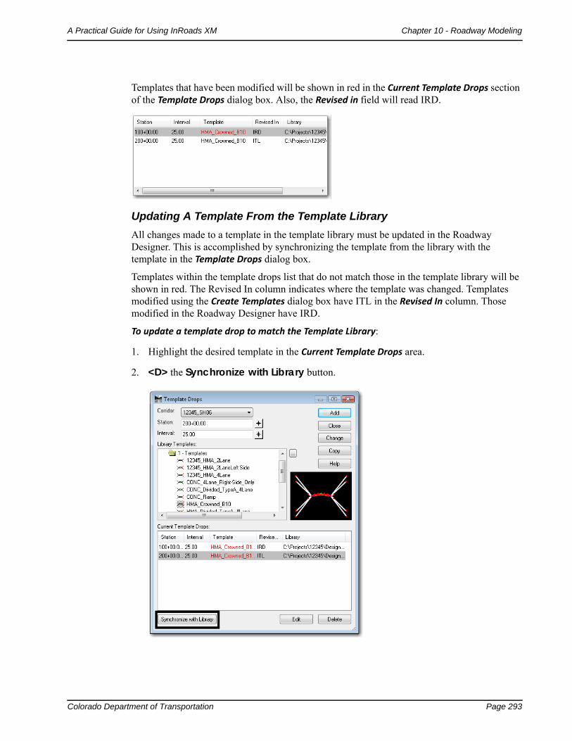
Templates that have been modified will be shown in red in the Current Template Drops section of the Template Drops dialog box. Also, the Revised in field will read IRD.
Updating A Template From the Template Library
All changes made to a template in the template library must be updated in the Roadway Designer. This is accomplished by synchronizing the template from the library with the template in the Template Drops dialog box.
Templates within the template drops list that do not match those in the template library will be shown in red. The Revised In column indicates where the template was changed. Templates modified using the Create Templates dialog box have ITL in the Revised In column. Those modified in the Roadway Designer have IRD.
To update a template drop to match the Template Library:
1. Highlight the desired template in the Current Template Drops area.
2. <D> the Synchronize with Library button.
Page 294 Colorado Department of Transportation
Chapter 10 - Roadway Modeling A Practical Guide for Using InRoads XM
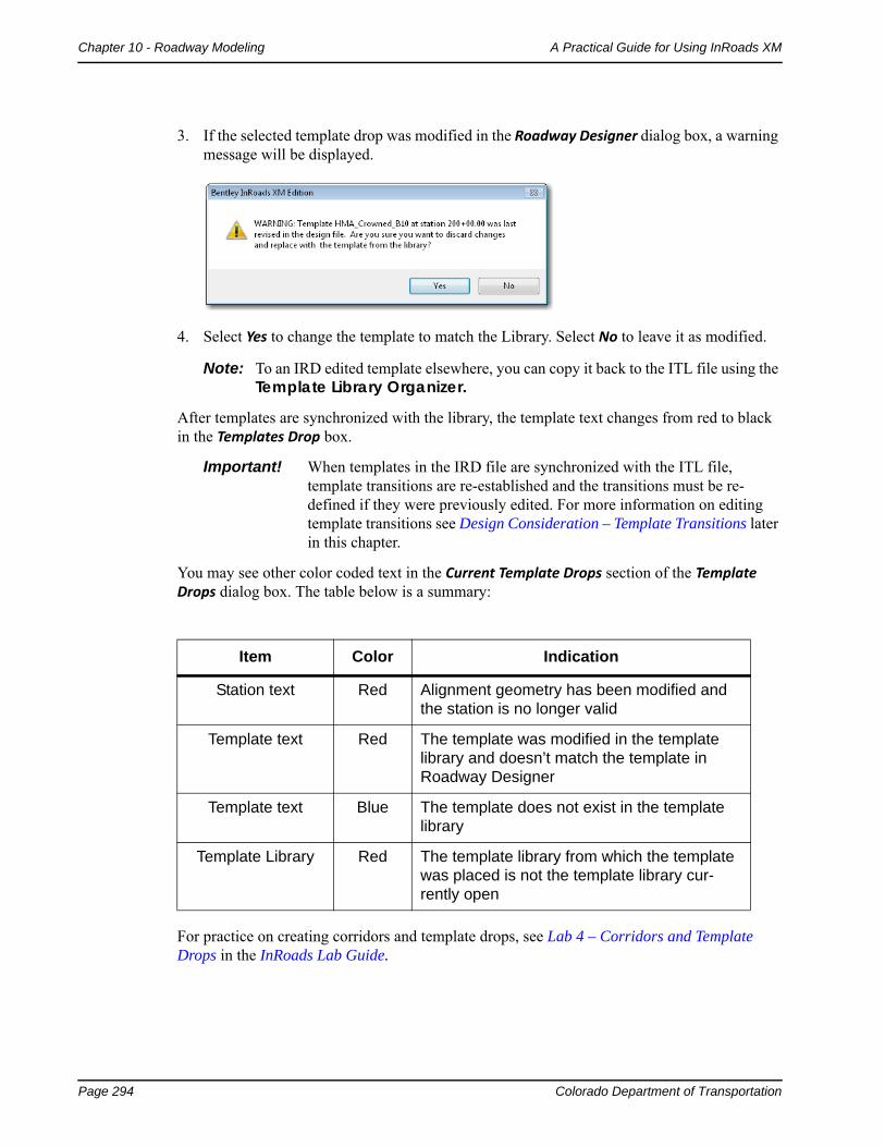
3. If the selected template drop was modified in the Roadway Designer dialog box, a warning message will be displayed.
4. Select Yes to change the template to match the Library. Select No to leave it as modified.
Note: To an IRD edited template elsewhere, you can copy it back to the ITL file using the Template Library Organizer.
After templates are synchronized with the library, the template text changes from red to black in the Templates Drop box.
Important! When templates in the IRD file are synchronized with the ITL file, template transitions are re-established and the transitions must be re-defined if they were previously edited. For more information on editing template transitions see Design Consideration – Template Transitions later in this chapter.
You may see other color coded text in the Current Template Drops section of the Template Drops dialog box. The table below is a summary:
For practice on creating corridors and template drops, see Lab 4 – Corridors and Template Drops in the InRoads Lab Guide.
Item Color Indication
Station text Red Alignment geometry has been modified and the station is no longer valid
Template text Red The template was modified in the template library and doesn’t match the template in Roadway Designer
Template text Blue The template does not exist in the template library
Template Library Red The template library from which the template was placed is not the template library cur-rently open
Colorado Department of Transportation Page 295
A Practical Guide for Using InRoads XM Chapter 10 - Roadway Modeling
Point Controls
Point Controls are used to override the template point constraints and redefine the location of points relative to an alignment, feature, or other corridor point. Using Point Controls will reduce the number of templates required for modeling, especially for corridors varying in lane and/or median width. There are many uses for point controls, including:
Divided highways that follow different horizontal and vertical alignments.
Introduction of right and left turn lanes.
Introduction of ramps, acceleration lanes, etc.
Following existing surface features for an overlay project.
Superelevation of template points.
Placement of independent ditches (ditches that follow a different path from the centerline).
Maintaining sideslopes within right-of-ways.
Introduction to Point Controls
Point Controls are defined in the Roadway Designer. Use Point Controls when you want to vary the location of template points without having to create multiple templates and multiple template drops in your corridor. For example, when introducing a right turn lane, instead of creating multiple right-turn lane templates and template drops for all the intermediate transition points, you could instead use Point Controls to assign the right lane point to follow a separate right turn alignment. You can also follow stations and offsets from the mainline alignment (for linear transitions) using either Point Controls or Parametric Constraints (see the section, Parametric Constraints, later in this chapter).
Note: Point Controls override the point constraints defined in the template.
Point Controls are defined and managed in Roadway Designer by selecting Corridor > Point Controls from the Roadway Designer menu bar.
Page 296 Colorado Department of Transportation
Chapter 10 - Roadway Modeling A Practical Guide for Using InRoads XM
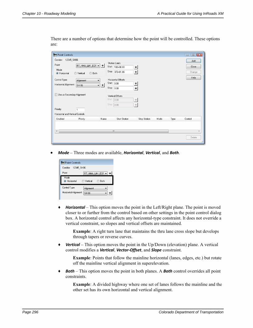
There are a number of options that determine how the point will be controlled. These options are:
Mode – Three modes are available, Horizontal, Vertical, and Both.
♦ Horizontal – This option moves the point in the Left/Right plane. The point is moved closer to or further from the control based on other settings in the point control dialog box. A horizontal control affects any horizontal-type constraint. It does not override a vertical constraint, so slopes and vertical offsets are maintained.
Example: A right turn lane that maintains the thru lane cross slope but develops through tapers or reverse curves.
♦ Vertical – This option moves the point in the Up/Down (elevation) plane. A vertical control modifies a Vertical, Vector‐Offset, and Slope constraint.
Example: Points that follow the mainline horizontal (lanes, edges, etc.) but rotate off the mainline vertical alignment in superelevation.
♦ Both – This option moves the point in both planes. A Both control overrides all point constraints.
Example: A divided highway where one set of lanes follows the mainline and the other set has its own horizontal and vertical alignment.
Colorado Department of Transportation Page 297
A Practical Guide for Using InRoads XM Chapter 10 - Roadway Modeling
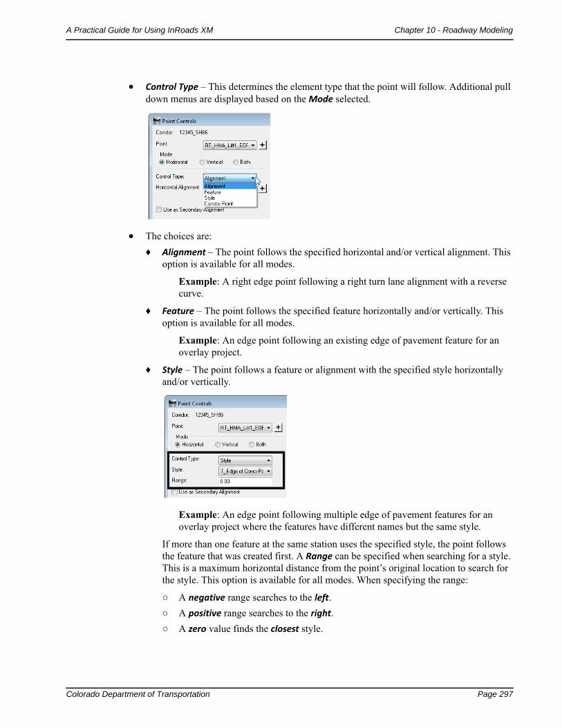
Control Type – This determines the element type that the point will follow. Additional pull down menus are displayed based on the Mode selected.
The choices are:
♦ Alignment – The point follows the specified horizontal and/or vertical alignment. This option is available for all modes.
Example: A right edge point following a right turn lane alignment with a reverse curve.
♦ Feature – The point follows the specified feature horizontally and/or vertically. This option is available for all modes.
Example: An edge point following an existing edge of pavement feature for an overlay project.
♦ Style – The point follows a feature or alignment with the specified style horizontally and/or vertically.
Example: An edge point following multiple edge of pavement features for an overlay project where the features have different names but the same style.
If more than one feature at the same station uses the specified style, the point follows the feature that was created first. A Range can be specified when searching for a style. This is a maximum horizontal distance from the point’s original location to search for the style. This option is available for all modes. When specifying the range:
○ A negative range searches to the left.
○ A positive range searches to the right.
○ A zero value finds the closest style.
Page 298 Colorado Department of Transportation
Chapter 10 - Roadway Modeling A Practical Guide for Using InRoads XM
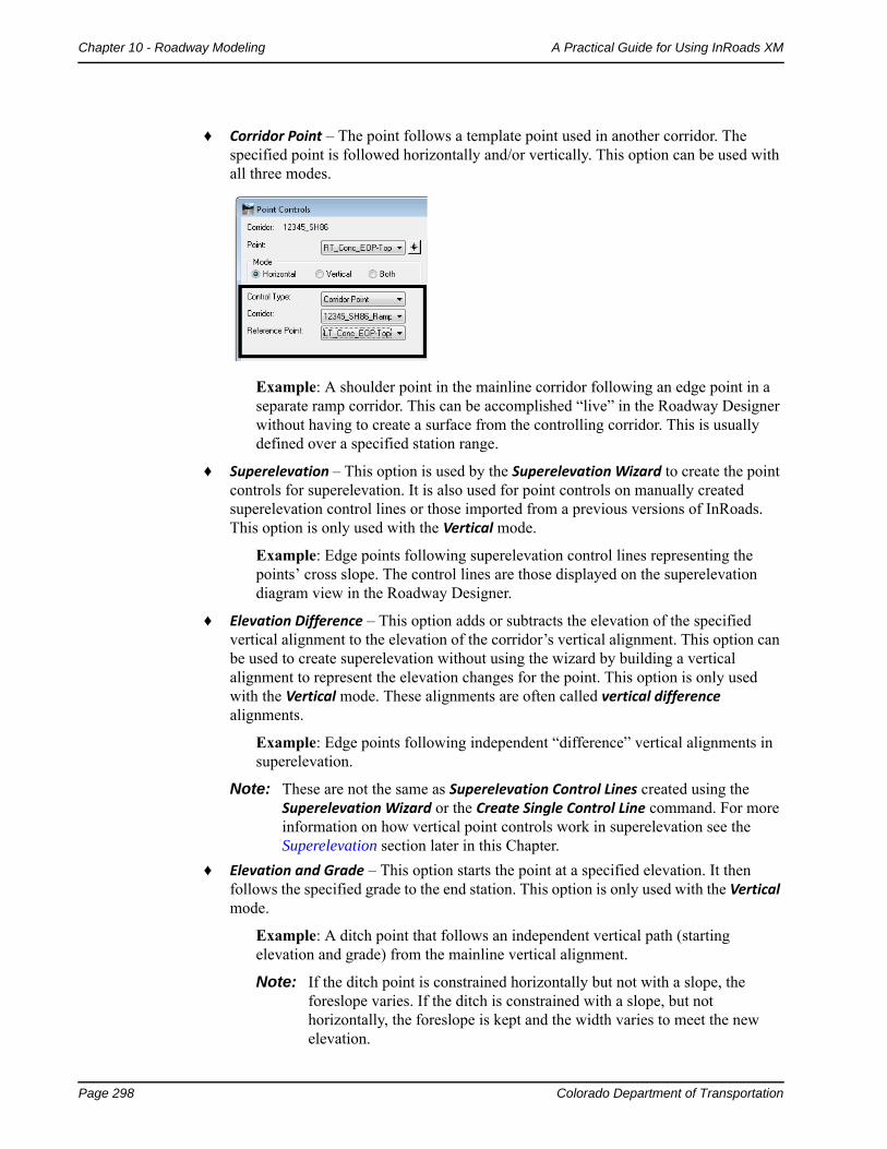
♦ Corridor Point – The point follows a template point used in another corridor. The specified point is followed horizontally and/or vertically. This option can be used with all three modes.
Example: A shoulder point in the mainline corridor following an edge point in a separate ramp corridor. This can be accomplished “live” in the Roadway Designer without having to create a surface from the controlling corridor. This is usually defined over a specified station range.
♦ Superelevation – This option is used by the Superelevation Wizard to create the point controls for superelevation. It is also used for point controls on manually created superelevation control lines or those imported from a previous versions of InRoads. This option is only used with the Vertical mode.
Example: Edge points following superelevation control lines representing the points’ cross slope. The control lines are those displayed on the superelevation diagram view in the Roadway Designer.
♦ Elevation Difference – This option adds or subtracts the elevation of the specified vertical alignment to the elevation of the corridor’s vertical alignment. This option can be used to create superelevation without using the wizard by building a vertical alignment to represent the elevation changes for the point. This option is only used with the Vertical mode. These alignments are often called vertical difference alignments.
Example: Edge points following independent “difference” vertical alignments in superelevation.
Note: These are not the same as Superelevation Control Lines created using the Superelevation Wizard or the Create Single Control Line command. For more information on how vertical point controls work in superelevation see the Superelevation section later in this Chapter.
♦ Elevation and Grade – This option starts the point at a specified elevation. It then follows the specified grade to the end station. This option is only used with the Vertical mode.
Example: A ditch point that follows an independent vertical path (starting elevation and grade) from the mainline vertical alignment.
Note: If the ditch point is constrained horizontally but not with a slope, the foreslope varies. If the ditch is constrained with a slope, but not horizontally, the foreslope is kept and the width varies to meet the new elevation.
Colorado Department of Transportation Page 299
A Practical Guide for Using InRoads XM Chapter 10 - Roadway Modeling
Station Limits – These set the beginning and ending stations for the control. The stations default to the length of the controlling element and its location relative to the corridor alignment stationing.
Horizontal Offsets – This is used to move the point a specified distance to the left or right of the control element. If the Start offset and Stop offsets are different, the point location varies linearly between the start and stop.
Vertical Offsets – This is used to move the point a specified distance above or below the control element. If the Start offset and Stop offsets are different, the point location varies linearly between the start and stop.
Note: If a separate alignment is not available for a point to follow, you can also vary the point by following horizontal and/or vertical offsets from the mainline alignment. This is useful for linear lane transitions (e.g. right turn lanes). However, if more complicated geometry for the lane is required (like a reverse curve), a separate alignment is needed.
Priority – This determines which control is used on a point with conflicting point controls. When there is a conflict, the control with the lower priority is used.
Note: Orange stations in the Point Controls list indicate points with overlapping or conflicting controls. The Control with the lowest priority is used.Red stations indicate an invalid station. The station may not exist because of changes to the alignment or the stations were keyed-in incorrectly. This could also mean that the alignment is missing.
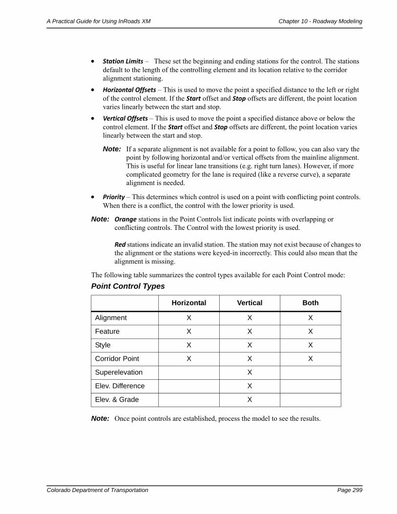
The following table summarizes the control types available for each Point Control mode:
Note: Once point controls are established, process the model to see the results.
Point Control Types
Horizontal Vertical Both
Alignment X X X
Feature X X X
Style X X X
Corridor Point X X X
Superelevation X
Elev. Difference X
Elev. & Grade X
Page 300 Colorado Department of Transportation
Chapter 10 - Roadway Modeling A Practical Guide for Using InRoads XM
Important! Even though point controls override template point constraints, the constraints still play a role in the final result. By default, point controls override the constraint that most closely matches the control type. For example, a vertical control will override a vertical or slope constraint rather than a horizontal constraint. While it is generally accepted best practice to fully constrain all points (with the exception of the centerline) in standard templates, there are situations where the constraints may need to be released in order to achieve the desired results with your point control. For example, if the point is horizontally and slope constrained and you assign a vertical control, the slope will change to meet the control. However, if the point has only a slope constraint and you assign a vertical control, the point will change horizontally by sliding along the slope constraint until it reaches the vertical assigned by the control.
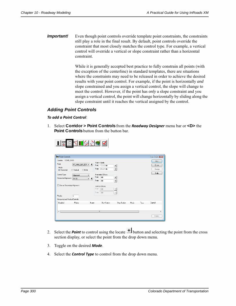
Adding Point Controls
To add a Point Control:
1. Select Corridor > Point Controls from the Roadway Designer menu bar or <D> the Point Controls button from the button bar.
2. Select the Point to control using the locate button and selecting the point from the cross section display, or select the point from the drop down menu.
3. Toggle on the desired Mode.
4. Select the Control Type to control from the drop down menu.

Colorado Department of Transportation Page 301
A Practical Guide for Using InRoads XM Chapter 10 - Roadway Modeling
5. Use the drop down menus and key-in fields to specify the controlling element. The options change based on the Control Type selected as shown below.
6. If you wish to limit the control within the default length of the controlling element, use the Start and Stop Station Limits.
7. In the Horizontal Offsets area, key in the desired Start offset.
8. Key in the desired Stop offset.
9. In the Vertical Offsets area, key in the desired Start offset.
10. Key in the desired Stop offset.
11. Key in the Priority for the control.
12. <D> the Add button to complete the control.
13. Repeat steps 2 through 12 for additional controls.
14. <D> the Close button to dismiss the Point Controls dialog box.
Editing Standard Point Controls
1. Select Corridor > Point Controls from the Roadway Designer menu bar or <D> the Point Controls button from the button bar.
2. Highlight the desired control in the Horizontal and Vertical Controls area.
3. Make the desired changes using the menus in the upper part of the dialog box.
Page 302 Colorado Department of Transportation
Chapter 10 - Roadway Modeling A Practical Guide for Using InRoads XM
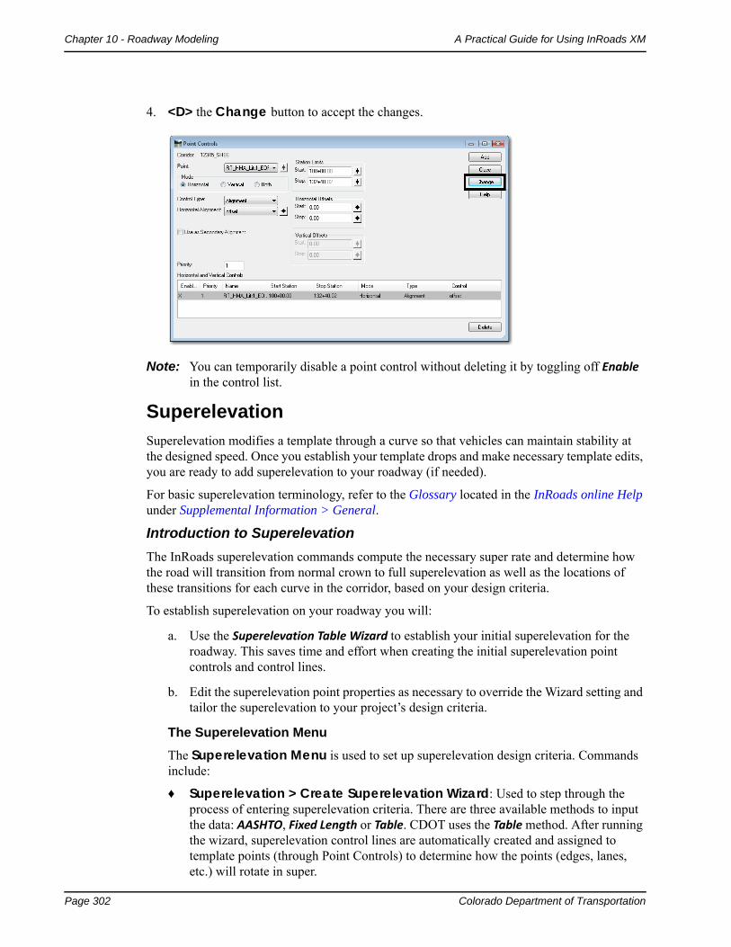
4. <D> the Change button to accept the changes.
Note: You can temporarily disable a point control without deleting it by toggling off Enable in the control list.
Superelevation
Superelevation modifies a template through a curve so that vehicles can maintain stability at the designed speed. Once you establish your template drops and make necessary template edits, you are ready to add superelevation to your roadway (if needed).
For basic superelevation terminology, refer to the Glossary located in the InRoads online Help under Supplemental Information > General.
Introduction to Superelevation
The InRoads superelevation commands compute the necessary super rate and determine how the road will transition from normal crown to full superelevation as well as the locations of these transitions for each curve in the corridor, based on your design criteria.
To establish superelevation on your roadway you will:
a. Use the Superelevation Table Wizard to establish your initial superelevation for the roadway. This saves time and effort when creating the initial superelevation point controls and control lines.
b. Edit the superelevation point properties as necessary to override the Wizard setting and tailor the superelevation to your project’s design criteria.
The Superelevation Menu
The Superelevation Menu is used to set up superelevation design criteria. Commands include:
♦ Superelevation > Create Superelevation Wizard: Used to step through the process of entering superelevation criteria. There are three available methods to input the data: AASHTO, Fixed Length or Table. CDOT uses the Table method. After running the wizard, superelevation control lines are automatically created and assigned to template points (through Point Controls) to determine how the points (edges, lanes, etc.) will rotate in super.
Colorado Department of Transportation Page 303
A Practical Guide for Using InRoads XM Chapter 10 - Roadway Modeling
♦ Superelevation > Create Single Control Line: An alternate method of setting up superelevation criteria by manually creating superelevation control lines, which controls the cross slope of template points in superelevation. This is also useful if you need to change the cross slope of the roadway when you’re not truly in superelevation, such as matching the vertical grade of the main roadway for an approach road.
♦ Superelevation > Apply Shoulder Rollover Lock: Allows you to create special superelevation control lines and assign point controls to shoulder points, which determine how shoulders will rotate in super. CDOT does not use rollover locks in standard situations, since the shoulders are fully superelevated.
♦ Superelevation > Import Superelevation: Allows you to import an ASCII superelevation file (pipe delimited format) to create superelevation control lines and assign point controls.
♦ Superelevation > Import Superelevation from Alignment: Allows you to import superelevation data from an InRoads alignment created in previous versions of InRoads (version 8.5 and earlier). This creates superelevation control lines matching the previous super table.
♦ Superelevation > Superelevation Report: Allows you to generate an XML report of the superelevated points and/or their corresponding control lines.
Note: The Superelevation Table Wizard (CDOT’s preferred method of setting up superelevation criteria) is explained below. For information on other methods or the concept of superelevation in general, refer to Superelevation Overview in the InRoads Online Help file.
The Superelevation Wizard
The Superelevation Wizard steps you through the process of entering your superelevation criteria. This criteria includes selecting the appropriate CDOT superelevation rate table.
Note: CDOT uses the Table method to calculate superelevation rates. This method complies with AASHTO guidelines and incorporates CDOT’s superelevation standards by utilizing custom superelevation tables located in the CDOT workspace.
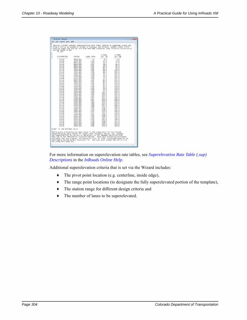
The CDOT superelevation tables specify maximum superelevation rates, along with spiral transition lengths, for a range of curve radii. The tables are text files, which can be opened in Notepad or any word processor. They are categorized by a maximum superelevation rate and a design speed. For example, a table named 06_55.sup contains CDOT standards for a 6% maximum superelevation rate at 55 mph design speed.
An example table is shown below:
Page 304 Colorado Department of Transportation
Chapter 10 - Roadway Modeling A Practical Guide for Using InRoads XM
For more information on superelevation rate tables, see Superelevation Rate Table (.sup) Descriptions in the InRoads Online Help.
Additional superelevation criteria that is set via the Wizard includes:
♦ The pivot point location (e.g. centerline, inside edge),
♦ The range point locations (to designate the fully superelevated portion of the template),
♦ The station range for different design criteria and
♦ The number of lanes to be superelevated.
Colorado Department of Transportation Page 305
A Practical Guide for Using InRoads XM Chapter 10 - Roadway Modeling
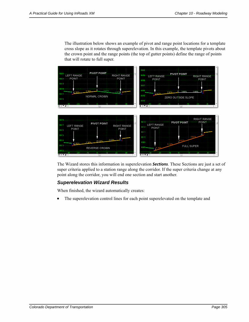
The illustration below shows an example of pivot and range point locations for a template cross slope as it rotates through superelevation. In this example, the template pivots about the crown point and the range points (the top of gutter points) define the range of points that will rotate to full super.
The Wizard stores this information in superelevation Sections. These Sections are just a set of super criteria applied to a station range along the corridor. If the super criteria change at any point along the corridor, you will end one section and start another.
Superelevation Wizard Results
When finished, the wizard automatically creates:
The superelevation control lines for each point superelevated on the template and
Page 306 Colorado Department of Transportation
Chapter 10 - Roadway Modeling A Practical Guide for Using InRoads XM
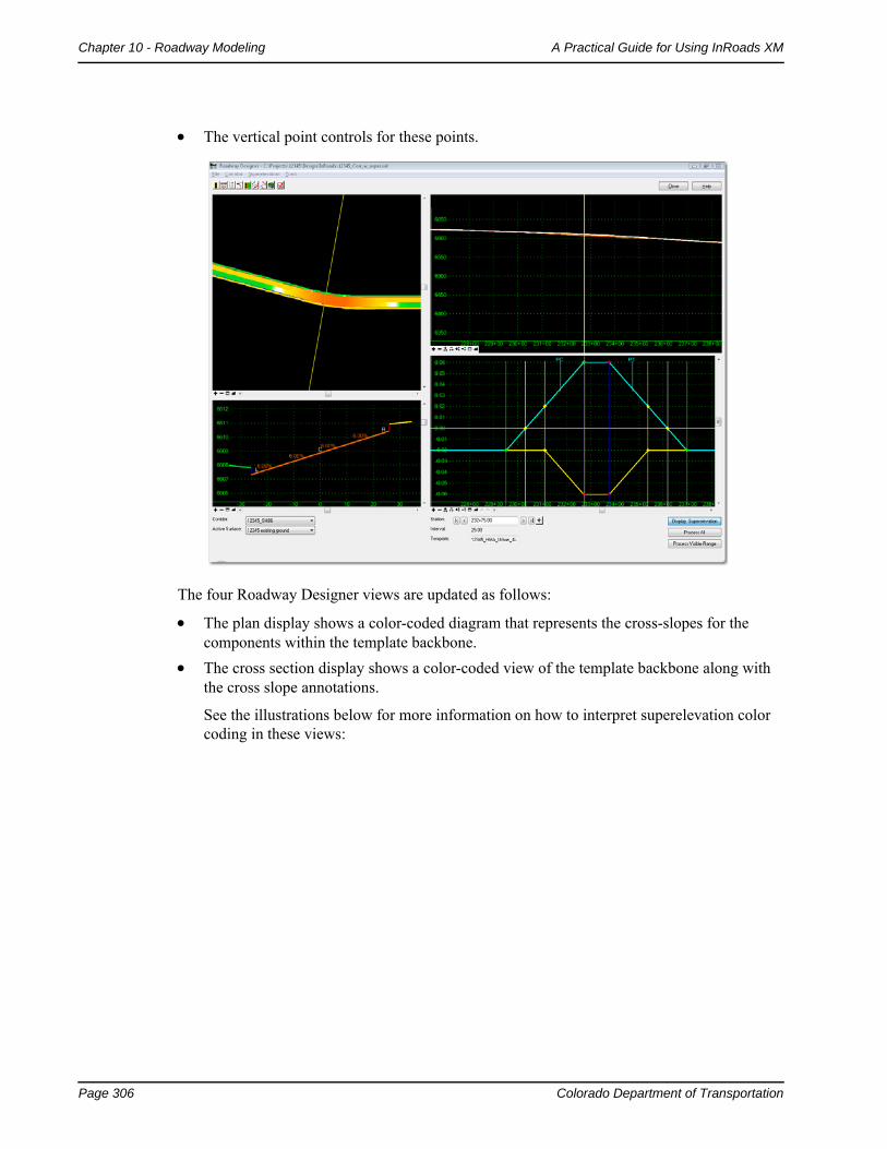
The vertical point controls for these points.
The four Roadway Designer views are updated as follows:
The plan display shows a color-coded diagram that represents the cross-slopes for the components within the template backbone.
The cross section display shows a color-coded view of the template backbone along with the cross slope annotations.
See the illustrations below for more information on how to interpret superelevation color coding in these views:
Colorado Department of Transportation Page 307
A Practical Guide for Using InRoads XM Chapter 10 - Roadway Modeling
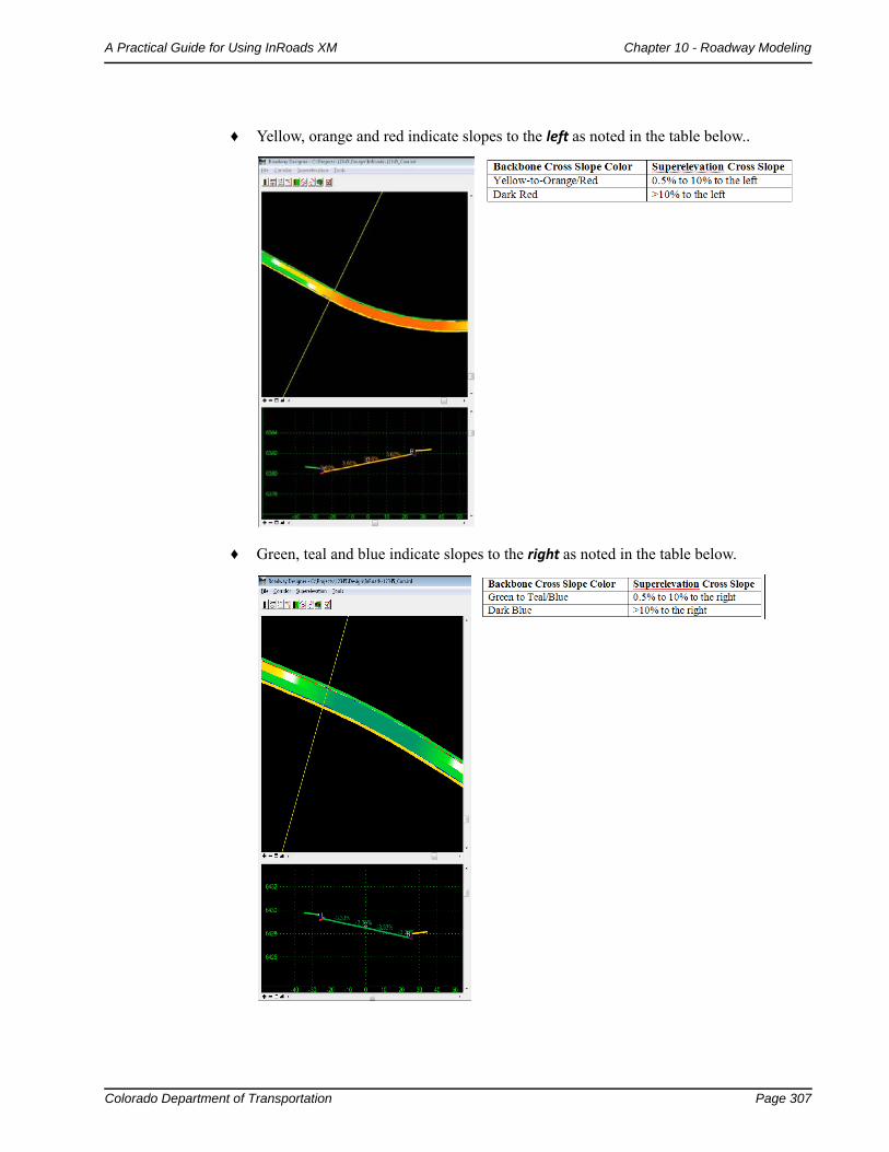
♦ Yellow, orange and red indicate slopes to the left as noted in the table below..
♦ Green, teal and blue indicate slopes to the right as noted in the table below.
Page 308 Colorado Department of Transportation
Chapter 10 - Roadway Modeling A Practical Guide for Using InRoads XM
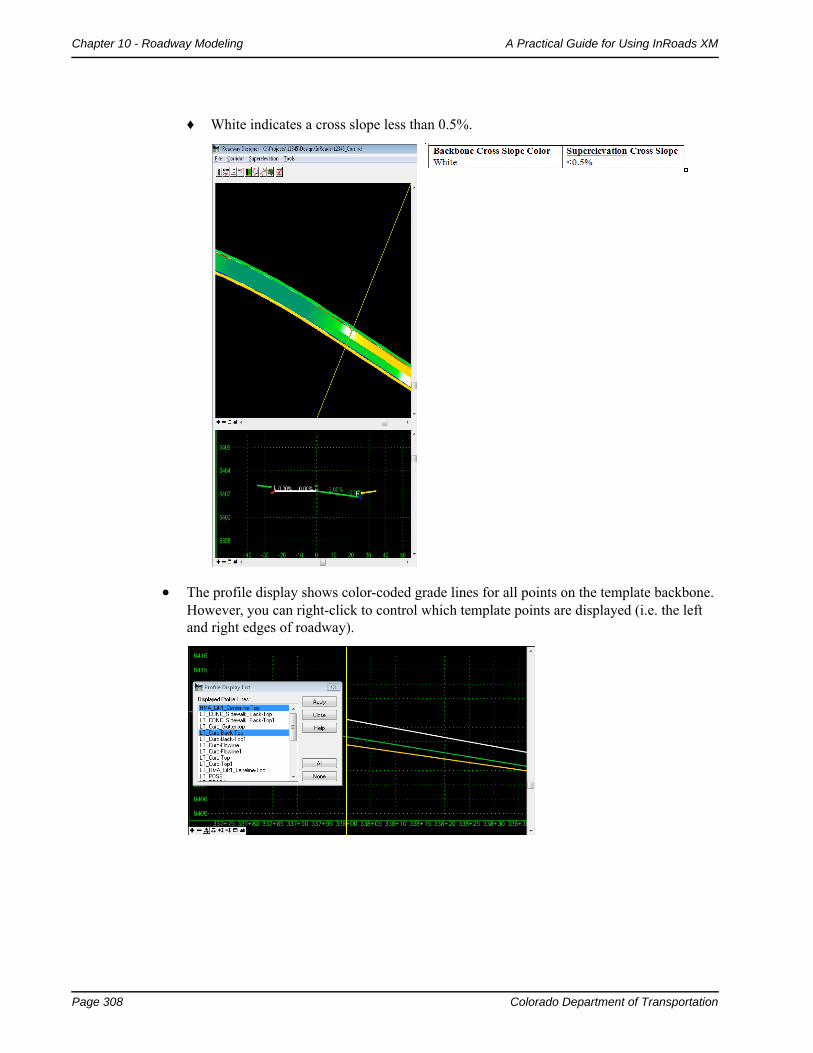
♦ White indicates a cross slope less than 0.5%.
The profile display shows color-coded grade lines for all points on the template backbone. However, you can right-click to control which template points are displayed (i.e. the left and right edges of roadway).
Colorado Department of Transportation Page 309
A Practical Guide for Using InRoads XM Chapter 10 - Roadway Modeling
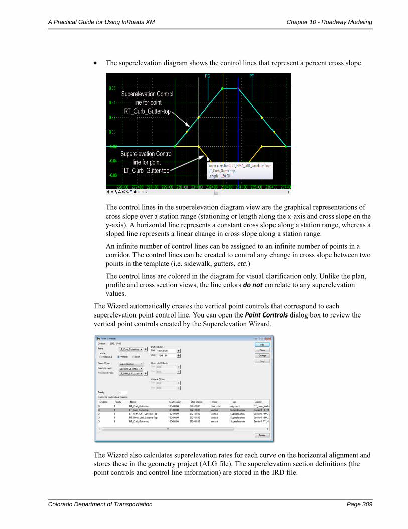
The superelevation diagram shows the control lines that represent a percent cross slope.
The control lines in the superelevation diagram view are the graphical representations of cross slope over a station range (stationing or length along the x-axis and cross slope on the y-axis). A horizontal line represents a constant cross slope along a station range, whereas a sloped line represents a linear change in cross slope along a station range.
An infinite number of control lines can be assigned to an infinite number of points in a corridor. The control lines can be created to control any change in cross slope between two points in the template (i.e. sidewalk, gutters, etc.)
The control lines are colored in the diagram for visual clarification only. Unlike the plan, profile and cross section views, the line colors do not correlate to any superelevation values.
The Wizard automatically creates the vertical point controls that correspond to each superelevation point control line. You can open the Point Controls dialog box to review the vertical point controls created by the Superelevation Wizard.
The Wizard also calculates superelevation rates for each curve on the horizontal alignment and stores these in the geometry project (ALG file). The superelevation section definitions (the point controls and control line information) are stored in the IRD file.
Page 310 Colorado Department of Transportation
Chapter 10 - Roadway Modeling A Practical Guide for Using InRoads XM
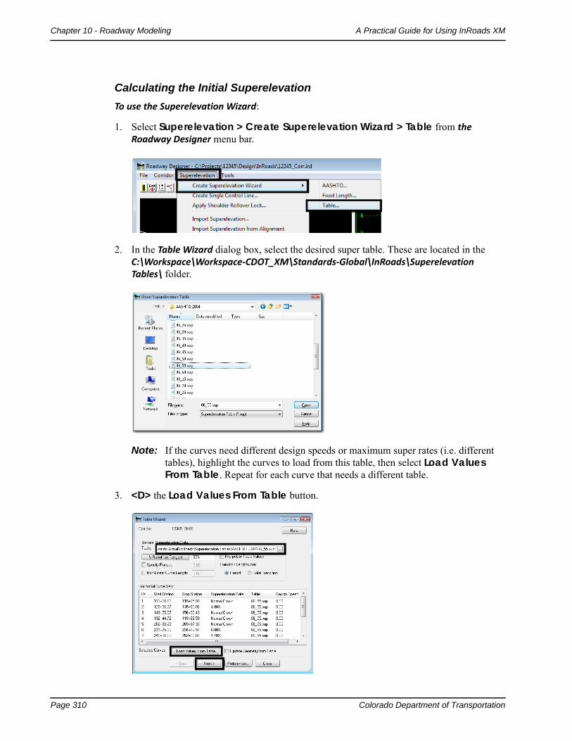
Calculating the Initial Superelevation
To use the Superelevation Wizard:
1. Select Superelevation > Create Superelevation Wizard > Table from the Roadway Designer menu bar.
2. In the Table Wizard dialog box, select the desired super table. These are located in the C:\Workspace\Workspace‐CDOT_XM\Standards‐Global\InRoads\Superelevation Tables\ folder.
Note: If the curves need different design speeds or maximum super rates (i.e. different tables), highlight the curves to load from this table, then select Load Values From Table. Repeat for each curve that needs a different table.
3. <D> the Load Values From Table button.
Colorado Department of Transportation Page 311
A Practical Guide for Using InRoads XM Chapter 10 - Roadway Modeling
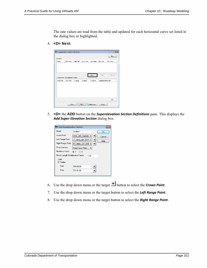
The rate values are read from the table and updated for each horizontal curve set listed in the dialog box or highlighted.
4. <D> Next.
5. <D> the ADD button on the Superelevation Section Definitions pane. This displays the Add Super Elevation Section dialog box.
6. Use the drop down menu or the target button to select the Crown Point.
7. Use the drop down menu or the target button to select the Left Range Point.
8. Use the drop down menu or the target button to select the Right Range Point.
Page 312 Colorado Department of Transportation
Chapter 10 - Roadway Modeling A Practical Guide for Using InRoads XM
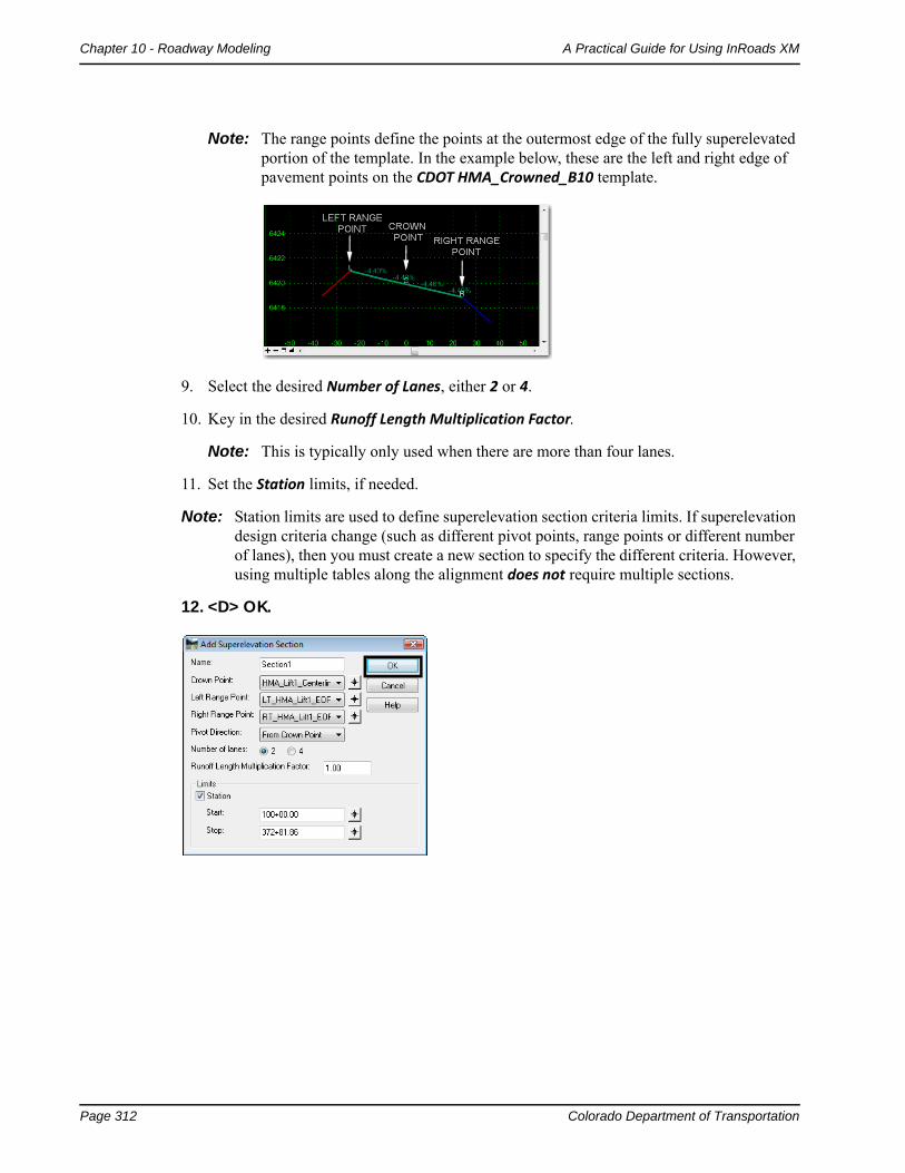
Note: The range points define the points at the outermost edge of the fully superelevated portion of the template. In the example below, these are the left and right edge of pavement points on the CDOT HMA_Crowned_B10 template.
9. Select the desired Number of Lanes, either 2 or 4.
10. Key in the desired Runoff Length Multiplication Factor.
Note: This is typically only used when there are more than four lanes.
11. Set the Station limits, if needed.
Note: Station limits are used to define superelevation section criteria limits. If superelevation design criteria change (such as different pivot points, range points or different number of lanes), then you must create a new section to specify the different criteria. However, using multiple tables along the alignment does not require multiple sections.
12. <D> OK.
Colorado Department of Transportation Page 313
A Practical Guide for Using InRoads XM Chapter 10 - Roadway Modeling
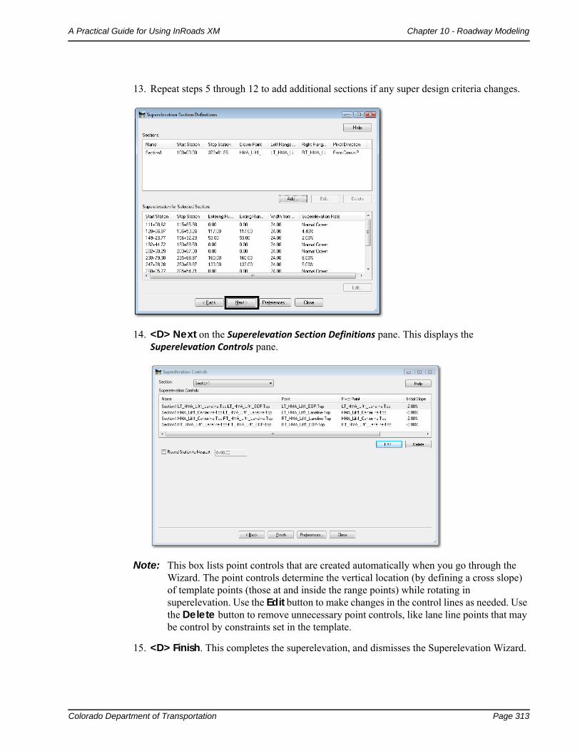
13. Repeat steps 5 through 12 to add additional sections if any super design criteria changes.
14. <D> Next on the Superelevation Section Definitions pane. This displays the Superelevation Controls pane.
Note: This box lists point controls that are created automatically when you go through the Wizard. The point controls determine the vertical location (by defining a cross slope) of template points (those at and inside the range points) while rotating in superelevation. Use the Edit button to make changes in the control lines as needed. Use the Delete button to remove unnecessary point controls, like lane line points that may be control by constraints set in the template.
15. <D> Finish. This completes the superelevation, and dismisses the Superelevation Wizard.
Page 314 Colorado Department of Transportation
Chapter 10 - Roadway Modeling A Practical Guide for Using InRoads XM
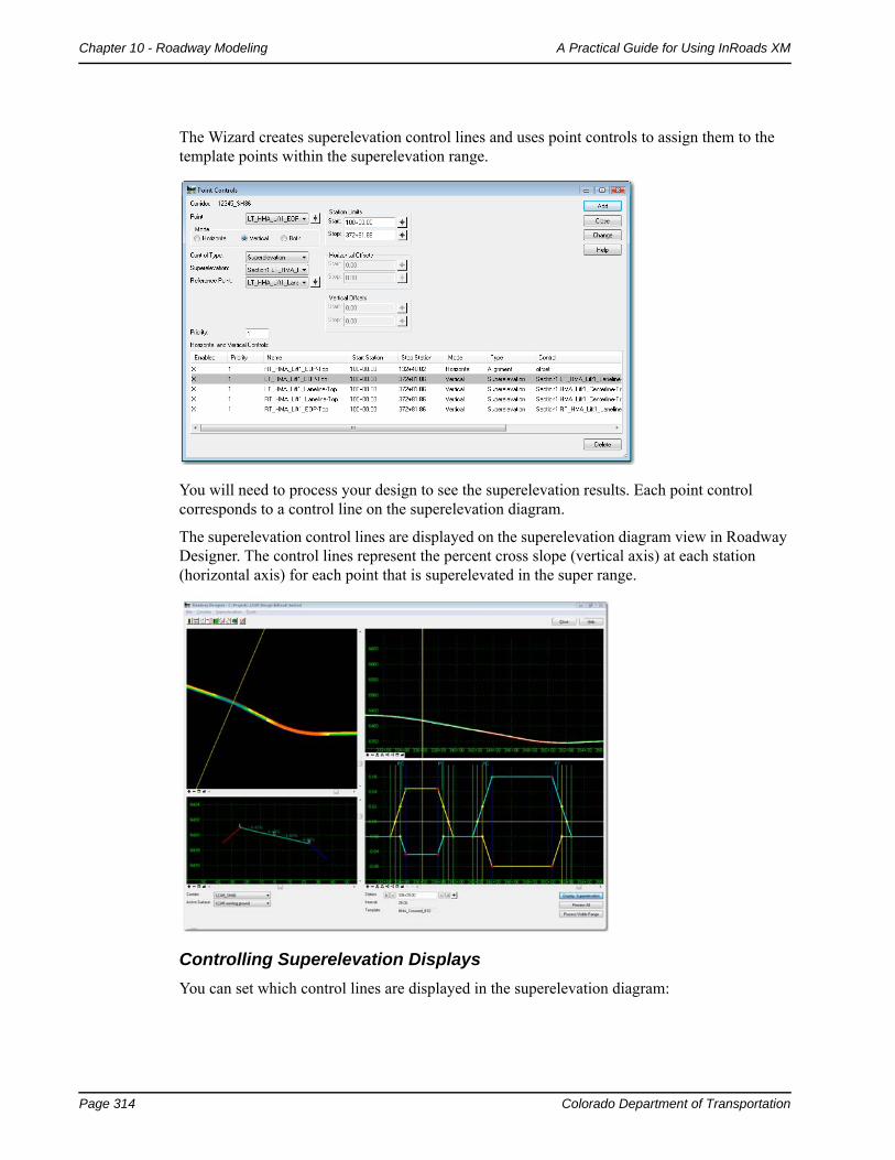
The Wizard creates superelevation control lines and uses point controls to assign them to the template points within the superelevation range.
You will need to process your design to see the superelevation results. Each point control corresponds to a control line on the superelevation diagram.
The superelevation control lines are displayed on the superelevation diagram view in Roadway Designer. The control lines represent the percent cross slope (vertical axis) at each station (horizontal axis) for each point that is superelevated in the super range.
Controlling Superelevation Displays
You can set which control lines are displayed in the superelevation diagram:
Colorado Department of Transportation Page 315
A Practical Guide for Using InRoads XM Chapter 10 - Roadway Modeling
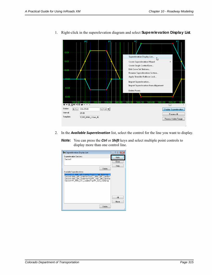
1. Right-click in the superelevation diagram and select Superelevation Display List.
2. In the Available Superelevation list, select the control for the line you want to display.
Note: You can press the Ctrl or Shift keys and select multiple point controls to display more than one control line.
Page 316 Colorado Department of Transportation
Chapter 10 - Roadway Modeling A Practical Guide for Using InRoads XM
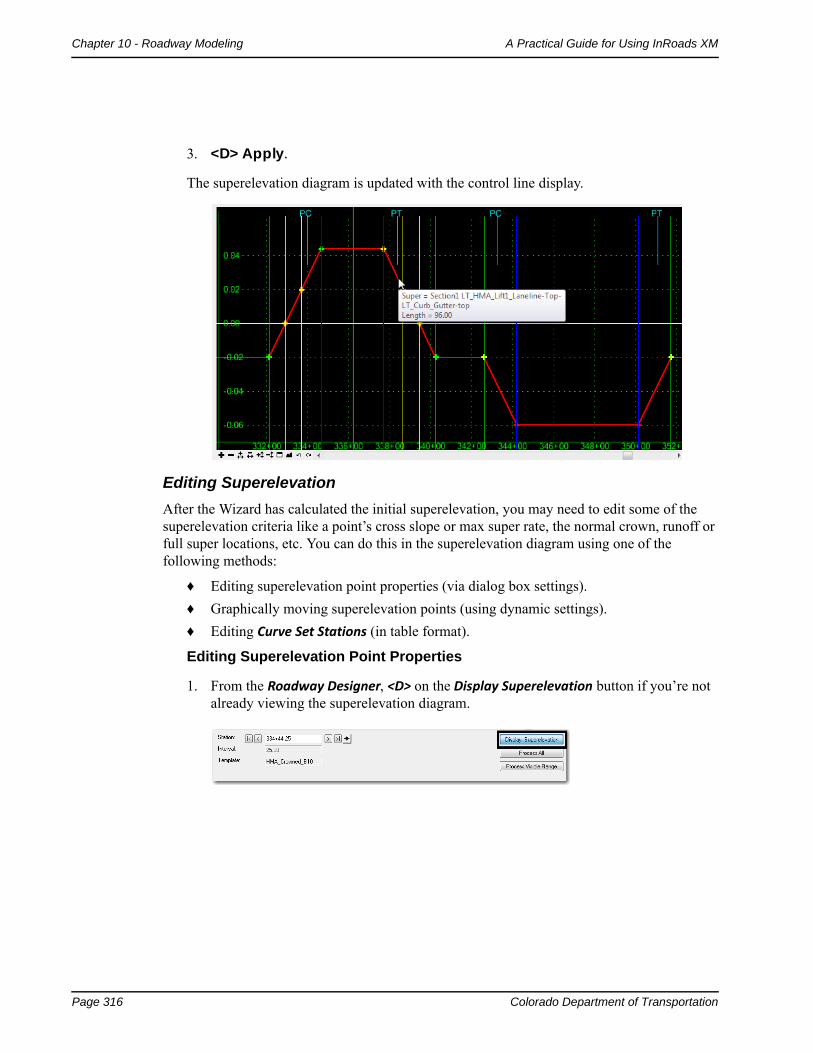
3. <D> Apply.
The superelevation diagram is updated with the control line display.
Editing Superelevation
After the Wizard has calculated the initial superelevation, you may need to edit some of the superelevation criteria like a point’s cross slope or max super rate, the normal crown, runoff or full super locations, etc. You can do this in the superelevation diagram using one of the following methods:
♦ Editing superelevation point properties (via dialog box settings).
♦ Graphically moving superelevation points (using dynamic settings).
♦ Editing Curve Set Stations (in table format).
Editing Superelevation Point Properties
1. From the Roadway Designer, <D> on the Display Superelevation button if you’re not already viewing the superelevation diagram.
Colorado Department of Transportation Page 317
A Practical Guide for Using InRoads XM Chapter 10 - Roadway Modeling
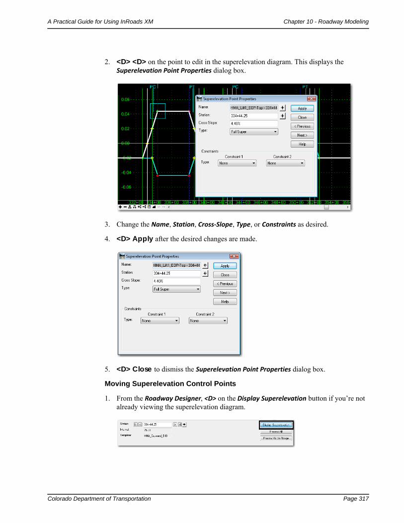
2. <D> <D> on the point to edit in the superelevation diagram. This displays the Superelevation Point Properties dialog box.
3. Change the Name, Station, Cross‐Slope, Type, or Constraints as desired.
4. <D> Apply after the desired changes are made.
5. <D> Close to dismiss the Superelevation Point Properties dialog box.
Moving Superelevation Control Points
1. From the Roadway Designer, <D> on the Display Superelevation button if you’re not already viewing the superelevation diagram.
Page 318 Colorado Department of Transportation
Chapter 10 - Roadway Modeling A Practical Guide for Using InRoads XM
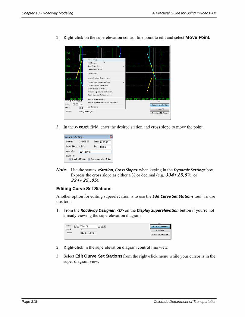
2. Right-click on the superelevation control line point to edit and select Move Point.
3. In the x+xx,x% field, enter the desired station and cross slope to move the point.
Note: Use the syntax <Station, Cross Slope> when keying in the Dynamic Settings box. Express the cross slope as either a % or decimal (e.g. 334+25,5% or 334+25,.05).
Editing Curve Set Stations
Another option for editing superelevation is to use the Edit Curve Set Stations tool. To use this tool:
1. From the Roadway Designer, <D> on the Display Superelevation button if you’re not already viewing the superelevation diagram.
2. Right-click in the superelevation diagram control line view.
3. Select Edit Curve Set Stations from the right-click menu while your cursor is in the super diagram view.
Colorado Department of Transportation Page 319
A Practical Guide for Using InRoads XM Chapter 10 - Roadway Modeling
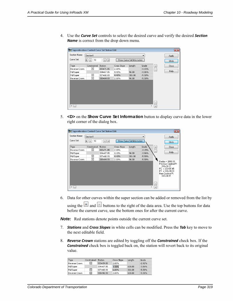
4. Use the Curve Set controls to select the desired curve and verify the desired Section Name is correct from the drop down menu.
5. <D> on the Show Curve Set Information button to display curve data in the lower right corner of the dialog box.
6. Data for other curves within the super section can be added or removed from the list by
using the and buttons to the right of the data area. Use the top buttons for data before the current curve, use the bottom ones for after the current curve.
Note: Red stations denote points outside the current curve set.
7. Stations and Cross Slopes in white cells can be modified. Press the Tab key to move to the next editable field.
8. Reverse Crown stations are edited by toggling off the Constrained check box. If the Constrained check box is toggled back on, the station will revert back to its original value.
Page 320 Colorado Department of Transportation
Chapter 10 - Roadway Modeling A Practical Guide for Using InRoads XM
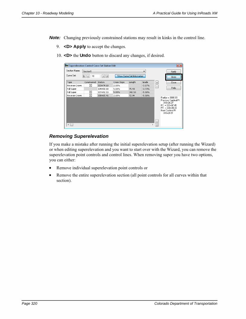
Note: Changing previously constrained stations may result in kinks in the control line.
9. <D> Apply to accept the changes.
10. <D> the Undo button to discard any changes, if desired.
Removing Superelevation
If you make a mistake after running the initial superelevation setup (after running the Wizard) or when editing superelevation and you want to start over with the Wizard, you can remove the superelevation point controls and control lines. When removing super you have two options, you can either:
Remove individual superelevation point controls or
Remove the entire superelevation section (all point controls for all curves within that section).
Colorado Department of Transportation Page 321
A Practical Guide for Using InRoads XM Chapter 10 - Roadway Modeling
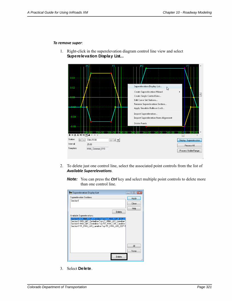
To remove super:
1. Right-click in the superelevation diagram control line view and select Superelevation Display List...
2. To delete just one control line, select the associated point controls from the list of Available Superelevations.
Note: You can press the Ctrl key and select multiple point controls to delete more than one control line.
3. Select Delete.
Page 322 Colorado Department of Transportation
Chapter 10 - Roadway Modeling A Practical Guide for Using InRoads XM
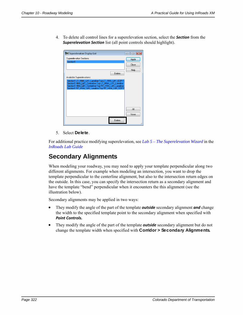
4. To delete all control lines for a superelevation section, select the Section from the Superelevation Section list (all point controls should highlight).
5. Select Delete.
For additional practice modifying superelevation, see Lab 5 – The Superelevation Wizard in the InRoads Lab Guide
Secondary Alignments
When modeling your roadway, you may need to apply your template perpendicular along two different alignments. For example when modeling an intersection, you want to drop the template perpendicular to the centerline alignment, but also to the intersection return edges on the outside. In this case, you can specify the intersection return as a secondary alignment and have the template “bend” perpendicular when it encounters the this alignment (see the illustration below).
Secondary alignments may be applied in two ways:
They modify the angle of the part of the template outside secondary alignment and change the width to the specified template point to the secondary alignment when specified with Point Controls.
They modify the angle of the part of the template outside secondary alignment but do not change the template width when specified with Corridor > Secondary Alignments.
Colorado Department of Transportation Page 323
A Practical Guide for Using InRoads XM Chapter 10 - Roadway Modeling
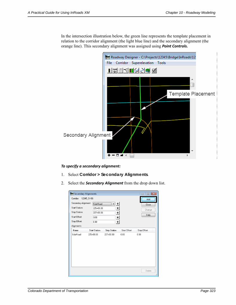
In the intersection illustration below, the green line represents the template placement in relation to the corridor alignment (the light blue line) and the secondary alignment (the orange line). This secondary alignment was assigned using Point Controls.
To specify a secondary alignment:
1. Select Corridor > Secondary Alignments.
2. Select the Secondary Alignment from the drop down list.
Page 324 Colorado Department of Transportation
Chapter 10 - Roadway Modeling A Practical Guide for Using InRoads XM
3. Specify a Start and Stop station range for InRoads to treat the alignment as secondary and “bend” the template.
4. Specify any Start and Stop Offsets from the alignment.
5. Select Add.
The alignment will only be treated as secondary through the station range specified.
Note: You can only have one secondary alignment per station range.
Note: To have the template widen and ‘kink’, create a point control as previous defined and toggle on the Secondary Alignment option.
Section Summary:♦ Roadway Designer is an interactive design modeling tool which allows you to see the
results of your design and then make edits before creating your proposed 3D surface.
♦ Before running Roadway Designer, you must have a horizontal or vertical alignment, an existing surface and one or more templates.
♦ The results of this interactive and iterative design process are shown in Roadway Designer’s plan, profile and cross section views.
♦ Design data for modeling is stored in the IRD file.
♦ A corridor defines a path for your project and can be defined with a horizontal and vertical alignments or with a surface feature.
♦ Templates Drops specify which templates are applied where along the corridor for modeling purposes.
♦ If templates are changed in the ITL file, then the template drops must be synchronized with the library to see the changes update in Roadway Designer.
♦ Point Controls are used to vary a template point by assigning the point to follow a different path.
♦ Establishing Point Controls can effectively reduce the number of templates and template drops required for modeling, especially when introducing turn lanes, ramps, etc.
♦ A point can be controlled using horizontal point controls, vertical point controls or both.
♦ There are several different types of controls that a point can follow including horizontal and/or vertical alignments, horizontal and/or vertical surface features, a feature style assigned to multiple features, or a point in another corridor.
♦ Superelevation is added to your roadway model using the Superelevation Table Wizard.
♦ Superelevation mode adds a fourth view to the Roadway Designer – a superelevation diagram control line view.
♦ The Superelevation Wizard automatically creates vertical point controls for certain backbone template points (lanes, edges, shoulders, etc.) as well as the super control lines for each of these points.
♦ The super control lines are displayed in the superelevation diagram control line view.
Colorado Department of Transportation Page 325
A Practical Guide for Using InRoads XM Chapter 10 - Roadway Modeling
♦ Superelevation can be edited by either editing point properties, graphically moving the super control line points, or editing a Curve Set table.
♦ Secondary alignments are used when you want to “bend” the template so that it is applied perpendicular to the secondary alignment (ramps, intersections, etc.).
Advanced Corridor Tools
You can take advantage of a couple of InRoads’ advanced corridor tools in certain design situations:
If you need to vary template points frequently over several different station ranges, you can use Parametric Constraints, which saves time creating multiple templates and template drops.
If you are working with multiple target surfaces or corridors, or designing a divided highway that may tie to multiple surfaces, then you can use Target Aliasing to set priority tie-ins.
Section Objectives:
♦ To learn how and when to use Parametric Constraints to vary template points.
♦ To learn how to assign labels to point constraints.
♦ To learn how to assign multiple surfaces and corridors as end condition targets using target aliasing.
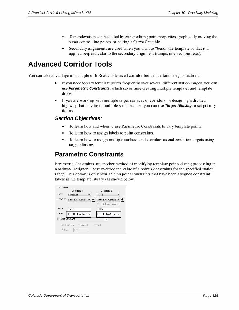
Parametric Constraints
Parametric Constraints are another method of modifying template points during processing in Roadway Designer. These override the value of a point’s constraints for the specified station range. This option is only available on point constraints that have been assigned constraint labels in the template library (as shown below).
Page 326 Colorado Department of Transportation
Chapter 10 - Roadway Modeling A Practical Guide for Using InRoads XM
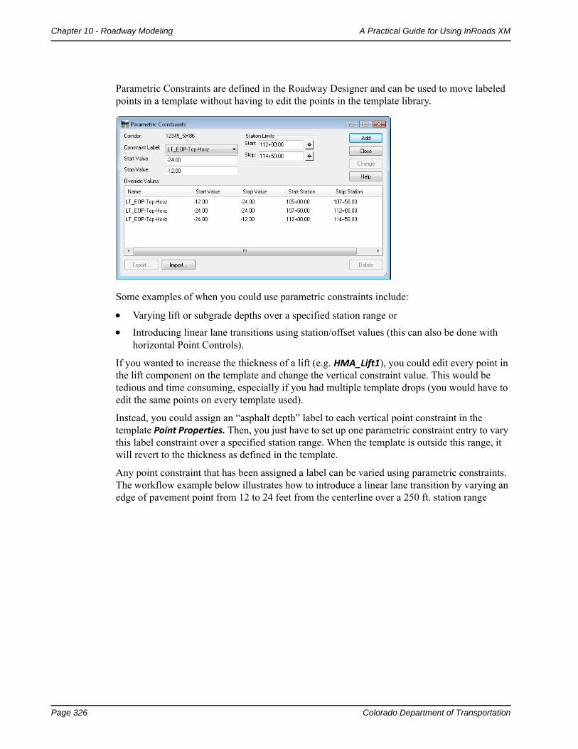
Parametric Constraints are defined in the Roadway Designer and can be used to move labeled points in a template without having to edit the points in the template library.
Some examples of when you could use parametric constraints include:
Varying lift or subgrade depths over a specified station range or
Introducing linear lane transitions using station/offset values (this can also be done with horizontal Point Controls).
If you wanted to increase the thickness of a lift (e.g. HMA_Lift1), you could edit every point in the lift component on the template and change the vertical constraint value. This would be tedious and time consuming, especially if you had multiple template drops (you would have to edit the same points on every template used).
Instead, you could assign an “asphalt depth” label to each vertical point constraint in the template Point Properties. Then, you just have to set up one parametric constraint entry to vary this label constraint over a specified station range. When the template is outside this range, it will revert to the thickness as defined in the template.
Any point constraint that has been assigned a label can be varied using parametric constraints. The workflow example below illustrates how to introduce a linear lane transition by varying an edge of pavement point from 12 to 24 feet from the centerline over a 250 ft. station range
Colorado Department of Transportation Page 327
A Practical Guide for Using InRoads XM Chapter 10 - Roadway Modeling
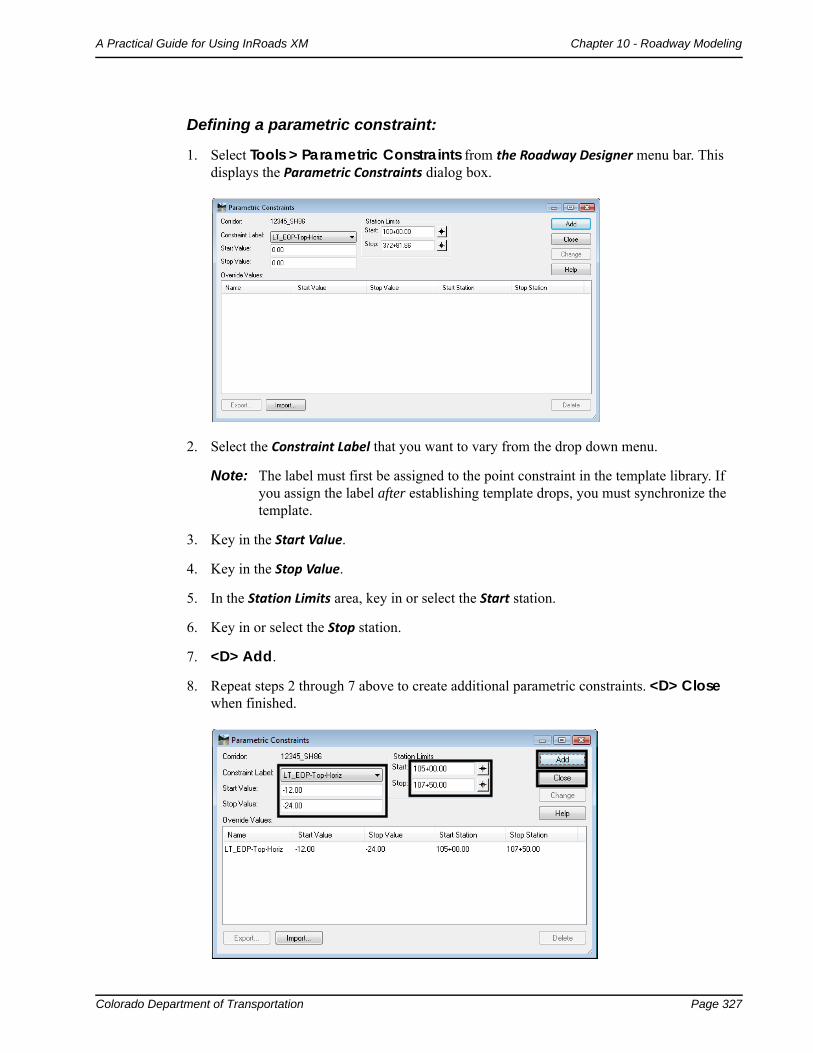
Defining a parametric constraint:
1. Select Tools > Parametric Constraints from the Roadway Designer menu bar. This displays the Parametric Constraints dialog box.
2. Select the Constraint Label that you want to vary from the drop down menu.
Note: The label must first be assigned to the point constraint in the template library. If you assign the label after establishing template drops, you must synchronize the template.
3. Key in the Start Value.
4. Key in the Stop Value.
5. In the Station Limits area, key in or select the Start station.
6. Key in or select the Stop station.
7. <D> Add.
8. Repeat steps 2 through 7 above to create additional parametric constraints. <D> Close when finished.
Page 328 Colorado Department of Transportation
Chapter 10 - Roadway Modeling A Practical Guide for Using InRoads XM
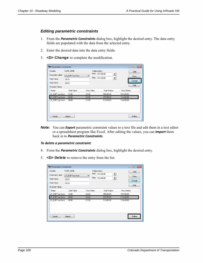
Editing parametric constraints
1. From the Parametric Constraints dialog box, highlight the desired entry. The data entry fields are populated with the data from the selected entry.
2. Enter the desired data into the data entry fields.
3. <D> Change to complete the modification.
Note: You can Export parametric constraint values to a text file and edit them in a text editor or a spreadsheet program like Excel. After editing the values, you can Import them back in to Parametric Constraints.
To delete a parametric constraint:
4. From the Parametric Constraints dialog box, highlight the desired entry.
5. <D> Delete to remove the entry from the list.
Colorado Department of Transportation Page 329
A Practical Guide for Using InRoads XM Chapter 10 - Roadway Modeling
Target Aliasing
Target aliasing is used to redefine the end condition targets assigned in the template library. Multiple targets can be prioritized, and the software attempts to solve the next target should the higher priority fail. Target Aliasing creates a prioritized list of surfaces, surface features, and/or corridor solutions that the current corridor can tie to. For example:
When you want to tie into multiple targets, as in when you are modeling across adjacent existing surfaces and need to tie to whichever is present at a given location.
When you want to tie to one surface if it is available, but a secondary surface if it is not. This may occur in the case of a divided highway being modeled as two corridors where you would like one set of lanes to tie to the other design surface if it’s close enough and to the existing if it’s not. This can be accomplished by creating the first design surface and using it as an alias for the existing, or both corridors can be modeled at the same time by using the corridor as the alias for the existing surface.
Target aliasing can also be used to remap the active surface. In many cases, a template can be simplified by only targeting active surface. However the active surface can easily change. By hard mapping the target alias to the existing surface of choice, you can mitigate opportunities to process the wrong active surface. Also, this allows you to see multiple surfaces in the cross section display window.
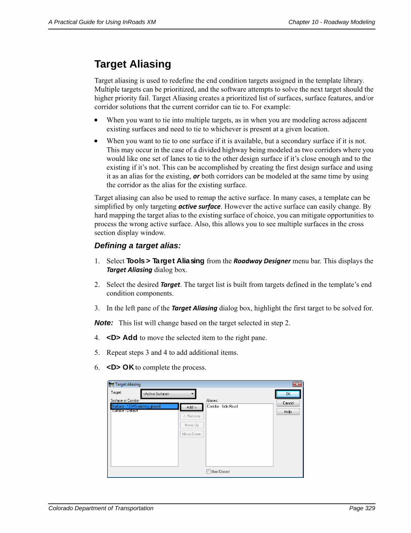
Defining a target alias:
1. Select Tools > Target Aliasing from the Roadway Designer menu bar. This displays the Target Aliasing dialog box.
2. Select the desired Target. The target list is built from targets defined in the template’s end condition components.
3. In the left pane of the Target Aliasing dialog box, highlight the first target to be solved for.
Note: This list will change based on the target selected in step 2.
4. <D> Add to move the selected item to the right pane.
5. Repeat steps 3 and 4 to add additional items.
6. <D> OK to complete the process.
Page 330 Colorado Department of Transportation
Chapter 10 - Roadway Modeling A Practical Guide for Using InRoads XM
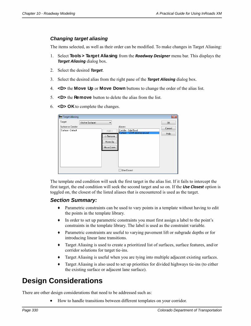
Changing target aliasing
The items selected, as well as their order can be modified. To make changes in Target Aliasing:
1. Select Tools > Target Aliasing from the Roadway Designer menu bar. This displays the Target Aliasing dialog box.
2. Select the desired Target.
3. Select the desired alias from the right pane of the Target Aliasing dialog box.
4. <D> the Move Up or Move Down buttons to change the order of the alias list.
5. <D> the Remove button to delete the alias from the list.
6. <D> OK to complete the changes.
The template end condition will seek the first target in the alias list. If it fails to intercept the first target, the end condition will seek the second target and so on. If the Use Closest option is toggled on, the closest of the listed aliases that is encountered is used as the target.
Section Summary:♦ Parametric constraints can be used to vary points in a template without having to edit
the points in the template library.
♦ In order to set up parametric constraints you must first assign a label to the point’s constraints in the template library. The label is used as the constraint variable.
♦ Parametric constraints are useful to varying pavement lift or subgrade depths or for introducing linear lane transitions.
♦ Target Aliasing is used to create a prioritized list of surfaces, surface features, and/or corridor solutions for target tie-ins.
♦ Target Aliasing is useful when you are tying into multiple adjacent existing surfaces.
♦ Target Aliasing is also used to set up priorities for divided highways tie-ins (to either the existing surface or adjacent lane surface).
Design Considerations
There are other design considerations that need to be addressed such as:
How to handle transitions between different templates on your corridor.
Colorado Department of Transportation Page 331
A Practical Guide for Using InRoads XM Chapter 10 - Roadway Modeling
How to smooth out end condition transitions or replace end conditions over a station range.
How to modify a single template drop to fit real a world condition
Section Objectives:
♦ To learn how to review and edit template transitions for proper point connections between templates on your corridor.
♦ To learn when you should edit template transitions.
♦ To understand the two different types of end condition exceptions.
♦ To learn how to modify end conditions and create end condition overrides and transitions without introducing template drops.
♦ To learn how to make a single station template edit to correct minor sideslope problems.
Template Transitions
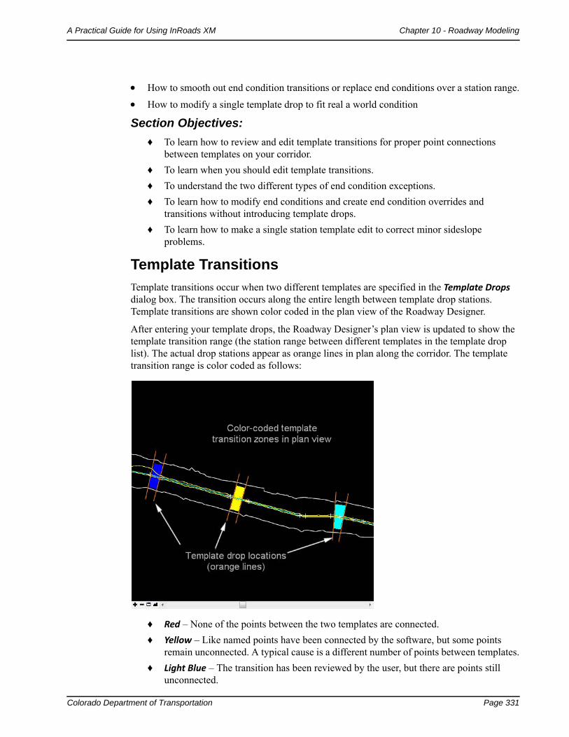
Template transitions occur when two different templates are specified in the Template Drops dialog box. The transition occurs along the entire length between template drop stations. Template transitions are shown color coded in the plan view of the Roadway Designer.
After entering your template drops, the Roadway Designer’s plan view is updated to show the template transition range (the station range between different templates in the template drop list). The actual drop stations appear as orange lines in plan along the corridor. The template transition range is color coded as follows:
♦ Red – None of the points between the two templates are connected.
♦ Yellow – Like named points have been connected by the software, but some points remain unconnected. A typical cause is a different number of points between templates.
♦ Light Blue – The transition has been reviewed by the user, but there are points still unconnected.
Page 332 Colorado Department of Transportation
Chapter 10 - Roadway Modeling A Practical Guide for Using InRoads XM
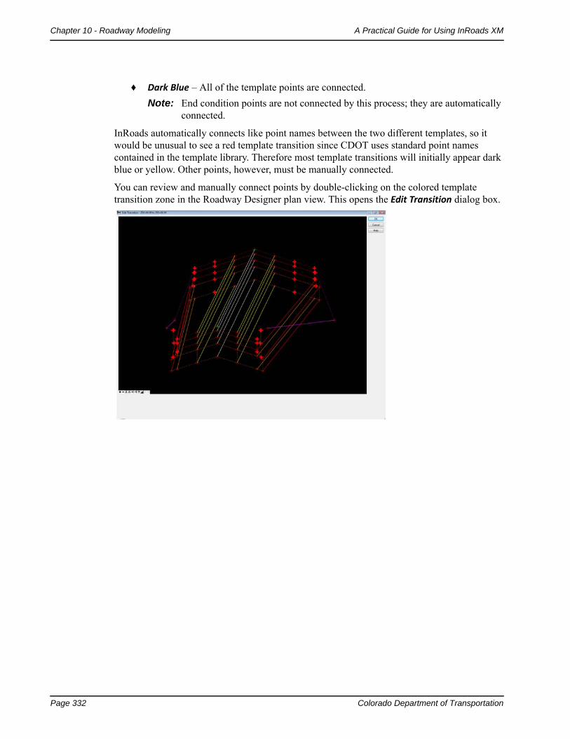
♦ Dark Blue – All of the template points are connected.
Note: End condition points are not connected by this process; they are automatically connected.
InRoads automatically connects like point names between the two different templates, so it would be unusual to see a red template transition since CDOT uses standard point names contained in the template library. Therefore most template transitions will initially appear dark blue or yellow. Other points, however, must be manually connected.
You can review and manually connect points by double-clicking on the colored template transition zone in the Roadway Designer plan view. This opens the Edit Transition dialog box.
Colorado Department of Transportation Page 333
A Practical Guide for Using InRoads XM Chapter 10 - Roadway Modeling
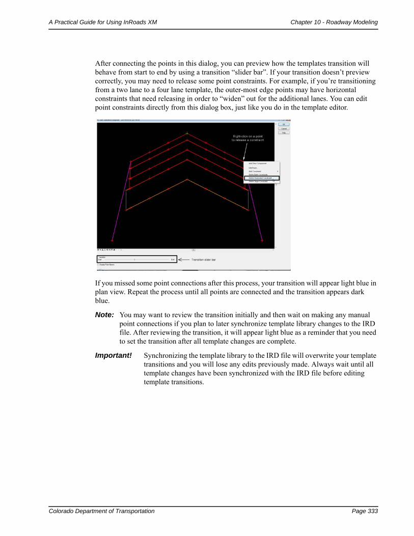
After connecting the points in this dialog, you can preview how the templates transition will behave from start to end by using a transition “slider bar”. If your transition doesn’t preview correctly, you may need to release some point constraints. For example, if you’re transitioning from a two lane to a four lane template, the outer-most edge points may have horizontal constraints that need releasing in order to “widen” out for the additional lanes. You can edit point constraints directly from this dialog box, just like you do in the template editor.
If you missed some point connections after this process, your transition will appear light blue in plan view. Repeat the process until all points are connected and the transition appears dark blue.
Note: You may want to review the transition initially and then wait on making any manual point connections if you plan to later synchronize template library changes to the IRD file. After reviewing the transition, it will appear light blue as a reminder that you need to set the transition after all template changes are complete.
Important! Synchronizing the template library to the IRD file will overwrite your template transitions and you will lose any edits previously made. Always wait until all template changes have been synchronized with the IRD file before editing template transitions.
Page 334 Colorado Department of Transportation
Chapter 10 - Roadway Modeling A Practical Guide for Using InRoads XM
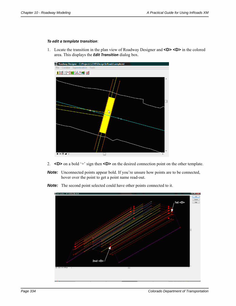
To edit a template transition:
1. Locate the transition in the plan view of Roadway Designer and <D> <D> in the colored area. This displays the Edit Transition dialog box.
2. <D> on a bold ‘+’ sign then <D> on the desired connection point on the other template.
Note: Unconnected points appear bold. If you’re unsure how points are to be connected, hover over the point to get a point name read-out.
Note: The second point selected could have other points connected to it.
Colorado Department of Transportation Page 335
A Practical Guide for Using InRoads XM Chapter 10 - Roadway Modeling
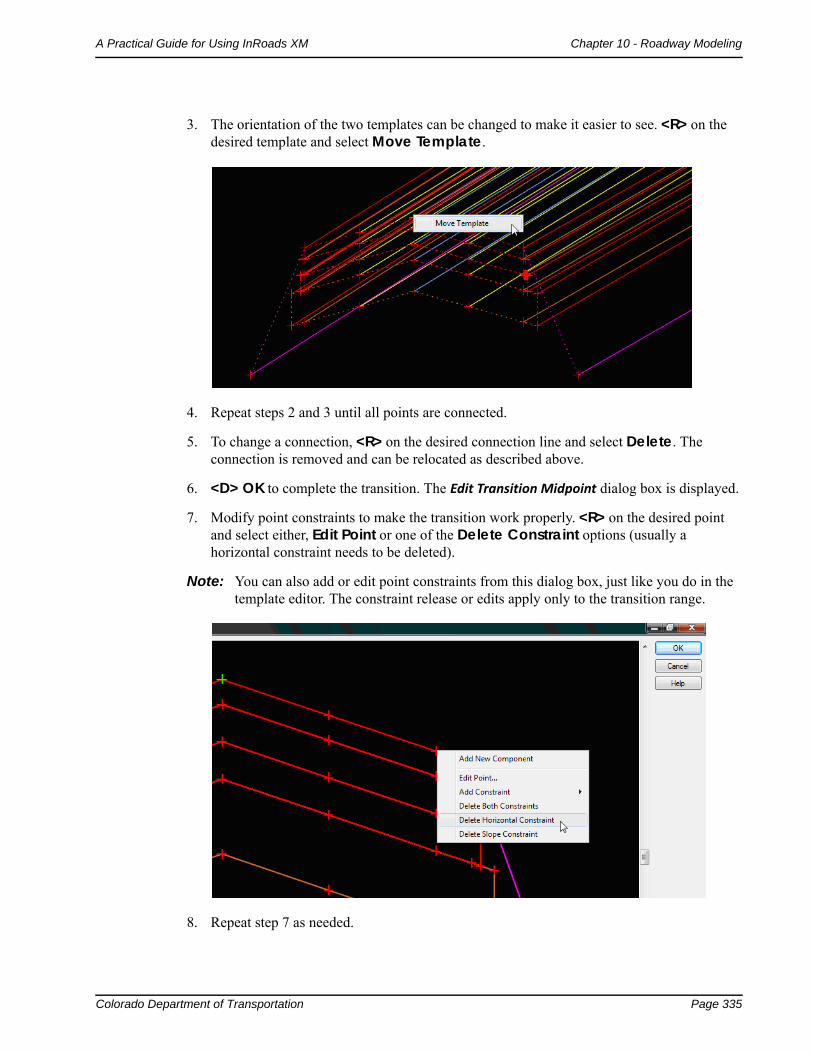
3. The orientation of the two templates can be changed to make it easier to see. <R> on the desired template and select Move Template.
4. Repeat steps 2 and 3 until all points are connected.
5. To change a connection, <R> on the desired connection line and select Delete. The connection is removed and can be relocated as described above.
6. <D> OK to complete the transition. The Edit Transition Midpoint dialog box is displayed.
7. Modify point constraints to make the transition work properly. <R> on the desired point and select either, Edit Point or one of the Delete Constraint options (usually a horizontal constraint needs to be deleted).
Note: You can also add or edit point constraints from this dialog box, just like you do in the template editor. The constraint release or edits apply only to the transition range.
8. Repeat step 7 as needed.
Page 336 Colorado Department of Transportation
Chapter 10 - Roadway Modeling A Practical Guide for Using InRoads XM
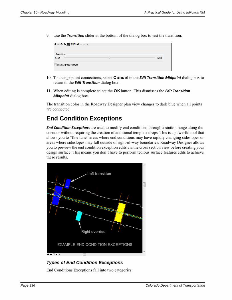
9. Use the Transition slider at the bottom of the dialog box to test the transition.
10. To change point connections, select Cancel in the Edit Transition Midpoint dialog box to return to the Edit Transition dialog box.
11. When editing is complete select the OK button. This dismisses the Edit Transition Midpoint dialog box.
The transition color in the Roadway Designer plan view changes to dark blue when all points are connected.
End Condition Exceptions
End Condition Exceptions are used to modify end conditions through a station range along the corridor without requiring the creation of additional template drops. This is a powerful tool that allows you to “fine tune” areas where end conditions may have rapidly changing sideslopes or areas where sideslopes may fall outside of right-of-way boundaries. Roadway Designer allows you to preview the end condition exception edits via the cross section view before creating your design surface. This means you don’t have to perform tedious surface features edits to achieve these results.
Types of End Condition Exceptions
End Conditions Exceptions fall into two categories:
Colorado Department of Transportation Page 337
A Practical Guide for Using InRoads XM Chapter 10 - Roadway Modeling
End condition overrides – the end condition slope and/or width is overridden, or replaced, with the edited end condition or a completely new end condition for the specified station range.
Example 1: Overriding a 6:1 sideslope from the template with a 3:1 override sideslope through a 300 ft. station range where the 6:1 sideslope falls outside the right-of-way limits.
Example 2: Replacing a v-bottom ditch from the template with a flat bottom override ditch through a specified cut range along the corridor.
End condition transitions – used to “smooth out” an end condition over a station range where the sideslope is changing due to terrain conditions. This is similar to template transitions except the transition occurs on an end condition component.
Example: Smoothing out a fill slope that changes back and forth between a 6:1 and a 3:1 slope over a 200 ft. station range. This is replaced with a gradual 6:1 to 3:1 transition over the same interval.
End condition exceptions are specified on either the right or left side. If you only need the exception on the left side, for example, you can maintain the template end condition on the right side. Or, you can set up different exceptions on the right and left side depending on the terrain conditions and sideslope behavior.
There is also a Backbone Only option that removes end conditions from the station range specified, which is useful in bridge or culvert areas.
InRoads uses a color coding system in Roadway Designer’s plan view to denote the two different types of exceptions:
♦ Light Blue – represents end condition overrides.
♦ Dark Blue – represents end condition exceptions.
Note: End condition exceptions are shown on the outside of the corridor to distinguish them from template transitions zones. which are shown inside.
Defining End Condition Exceptions
Defining an end condition exception is a two part process:
a. Adding the exception entry by specifying the station range and designating it as a left/right override or left/right transition.
b. Editing the exception to modify the behavior of the end condition (this is similar to editing a point on a template and/or editing a template transition).
Follow the steps below to define an end condition exception:
1. Select Corridor > End Condition Exceptions from the Roadway Designer menu bar, or <D> on the End Condition Exceptions button from the button bar to open the End Condition Exceptions dialog box.
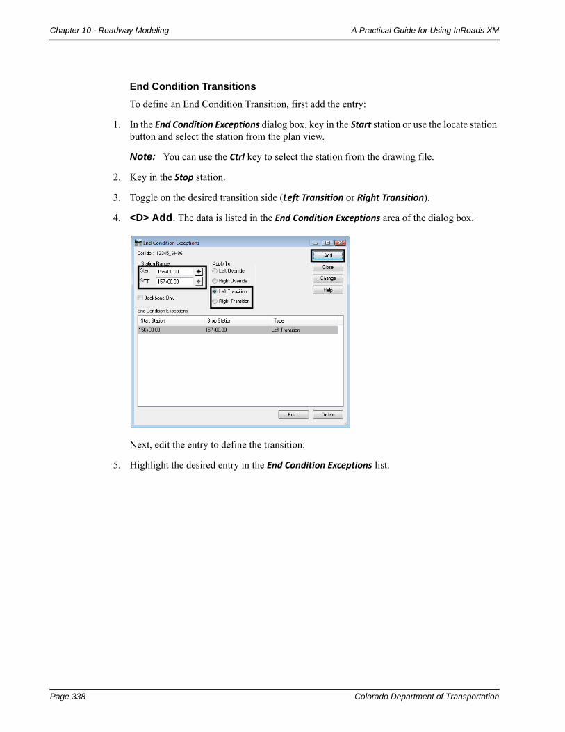
Page 338 Colorado Department of Transportation
Chapter 10 - Roadway Modeling A Practical Guide for Using InRoads XM
End Condition Transitions
To define an End Condition Transition, first add the entry:
1. In the End Condition Exceptions dialog box, key in the Start station or use the locate station button and select the station from the plan view.
Note: You can use the Ctrl key to select the station from the drawing file.
2. Key in the Stop station.
3. Toggle on the desired transition side (Left Transition or Right Transition).
4. <D> Add. The data is listed in the End Condition Exceptions area of the dialog box.
Next, edit the entry to define the transition:
5. Highlight the desired entry in the End Condition Exceptions list.
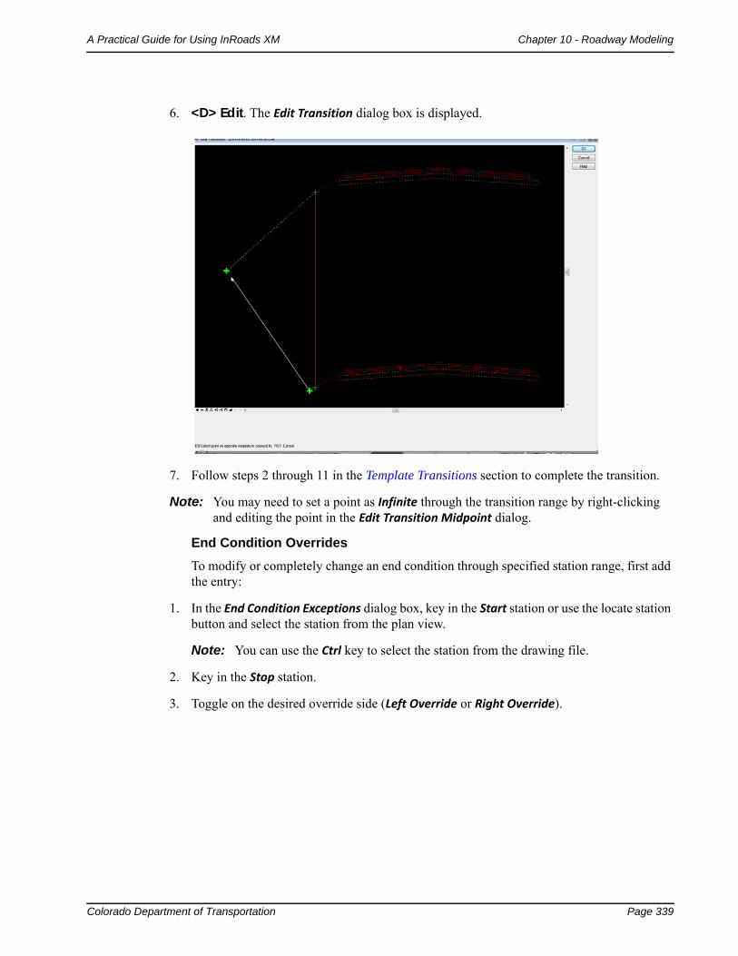
Colorado Department of Transportation Page 339
A Practical Guide for Using InRoads XM Chapter 10 - Roadway Modeling
6. <D> Edit. The Edit Transition dialog box is displayed.
7. Follow steps 2 through 11 in the Template Transitions section to complete the transition.
Note: You may need to set a point as Infinite through the transition range by right-clicking and editing the point in the Edit Transition Midpoint dialog.
End Condition Overrides
To modify or completely change an end condition through specified station range, first add the entry:
1. In the End Condition Exceptions dialog box, key in the Start station or use the locate station button and select the station from the plan view.
Note: You can use the Ctrl key to select the station from the drawing file.
2. Key in the Stop station.
3. Toggle on the desired override side (Left Override or Right Override).
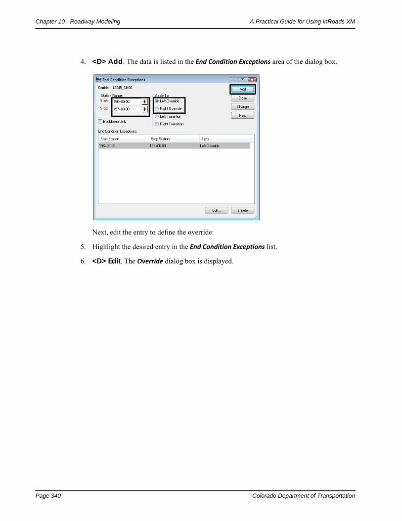
Page 340 Colorado Department of Transportation
Chapter 10 - Roadway Modeling A Practical Guide for Using InRoads XM
4. <D> Add. The data is listed in the End Condition Exceptions area of the dialog box.
Next, edit the entry to define the override:
5. Highlight the desired entry in the End Condition Exceptions list.
6. <D> Edit. The Override dialog box is displayed.
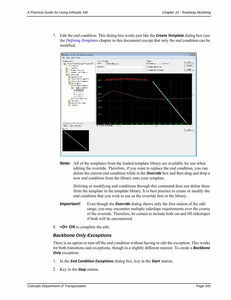
Colorado Department of Transportation Page 341
A Practical Guide for Using InRoads XM Chapter 10 - Roadway Modeling
7. Edit the end condition. This dialog box works just like the Create Template dialog box (see the Defining Templates chapter in this document) except that only the end condition can be modified.
Note: All of the templates from the loaded template library are available for use when editing the override. Therefore, if you want to replace the end condition, you can delete the current end condition while in the Override box and then drag and drop a new end condition from the library onto your template.
Deleting or modifying end conditions through this command does not delete them from the template in the template library. It is best practice to create or modify the end condition that you wish to use as the override first in the library.
Important! Even though the Override dialog shows only the first station of the edit range, you may encounter multiple sideslope requirements over the course of the override. Therefore, be certain to include both cut and fill sideslopes if both will be encountered.
8. <D> OK to complete the edit.
Backbone Only Exceptions
There is an option to turn off the end condition without having to edit the exception. This works for both transitions and exceptions, though in a slightly different manner. To create a Backbone Only exception:
1. In the End Condition Exceptions dialog box, key in the Start station.
2. Key in the Stop station.
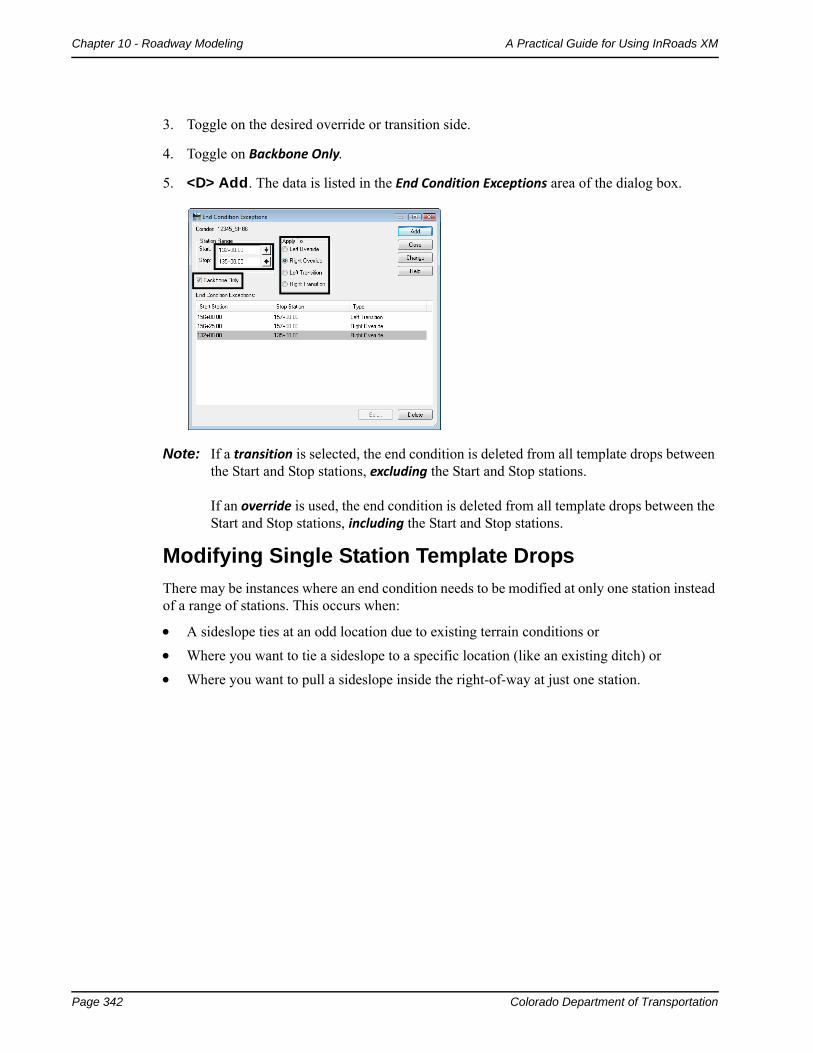
Page 342 Colorado Department of Transportation
Chapter 10 - Roadway Modeling A Practical Guide for Using InRoads XM
3. Toggle on the desired override or transition side.
4. Toggle on Backbone Only.
5. <D> Add. The data is listed in the End Condition Exceptions area of the dialog box.
Note: If a transition is selected, the end condition is deleted from all template drops between the Start and Stop stations, excluding the Start and Stop stations. If an override is used, the end condition is deleted from all template drops between the Start and Stop stations, including the Start and Stop stations.
Modifying Single Station Template Drops
There may be instances where an end condition needs to be modified at only one station instead of a range of stations. This occurs when:
A sideslope ties at an odd location due to existing terrain conditions or
Where you want to tie a sideslope to a specific location (like an existing ditch) or
Where you want to pull a sideslope inside the right-of-way at just one station.
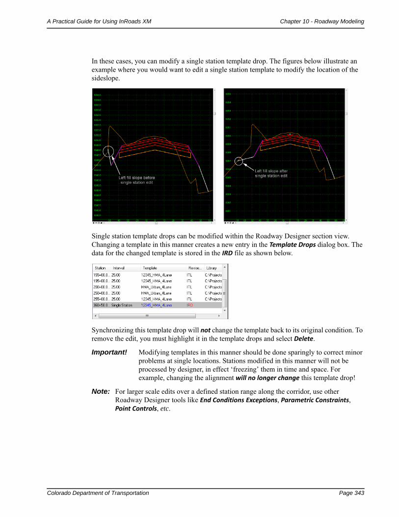
Colorado Department of Transportation Page 343
A Practical Guide for Using InRoads XM Chapter 10 - Roadway Modeling
In these cases, you can modify a single station template drop. The figures below illustrate an example where you would want to edit a single station template to modify the location of the sideslope.
Single station template drops can be modified within the Roadway Designer section view. Changing a template in this manner creates a new entry in the Template Drops dialog box. The data for the changed template is stored in the IRD file as shown below.
Synchronizing this template drop will not change the template back to its original condition. To remove the edit, you must highlight it in the template drops and select Delete.
Important! Modifying templates in this manner should be done sparingly to correct minor problems at single locations. Stations modified in this manner will not be processed by designer, in effect ‘freezing’ them in time and space. For example, changing the alignment will no longer change this template drop!
Note: For larger scale edits over a defined station range along the corridor, use other Roadway Designer tools like End Conditions Exceptions, Parametric Constraints, Point Controls, etc.
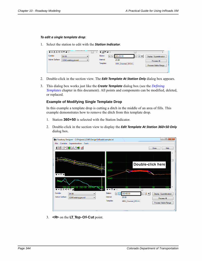
Page 344 Colorado Department of Transportation
Chapter 10 - Roadway Modeling A Practical Guide for Using InRoads XM
To edit a single template drop:
1. Select the station to edit with the Station Indicator.
2. Double-click in the section view. The Edit Template At Station Only dialog box appears.
3. This dialog box works just like the Create Template dialog box (see the Defining Templates chapter in this document). All points and components can be modified, deleted, or replaced.
Example of Modifying Single Template Drop
In this example a template drop is cutting a ditch in the middle of an area of fills. This example demonstrates how to remove the ditch from this template drop.
1. Station 360+50 is selected with the Station Indicator.
2. Double-click in the section view to display the Edit Template At Station 360+50 Only dialog box.
3. <R> on the LT_Top-Of-Cut point.
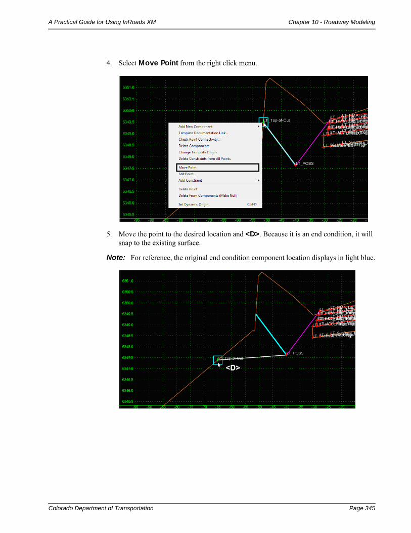
Colorado Department of Transportation Page 345
A Practical Guide for Using InRoads XM Chapter 10 - Roadway Modeling
4. Select Move Point from the right click menu.
5. Move the point to the desired location and <D>. Because it is an end condition, it will snap to the existing surface.
Note: For reference, the original end condition component location displays in light blue.
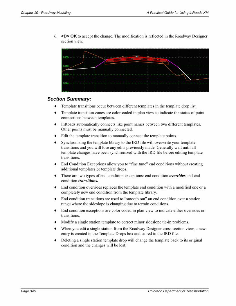
Page 346 Colorado Department of Transportation
Chapter 10 - Roadway Modeling A Practical Guide for Using InRoads XM
6. <D> OK to accept the change. The modification is reflected in the Roadway Designer section view.
Section Summary:♦ Template transitions occur between different templates in the template drop list.
♦ Template transition zones are color-coded in plan view to indicate the status of point connections between templates.
♦ InRoads automatically connects like point names between two different templates. Other points must be manually connected.
♦ Edit the template transition to manually connect the template points.
♦ Synchronizing the template library to the IRD file will overwrite your template transitions and you will lose any edits previously made. Generally wait until all template changes have been synchronized with the IRD file before editing template transitions.
♦ End Condition Exceptions allow you to “fine tune” end conditions without creating additional templates or template drops.
♦ There are two types of end condition exceptions: end condition overrides and end condition transitions.
♦ End condition overrides replaces the template end condition with a modified one or a completely new end condition from the template library.
♦ End condition transitions are used to “smooth out” an end condition over a station range where the sideslope is changing due to terrain conditions.
♦ End condition exceptions are color coded in plan view to indicate either overrides or transitions.
♦ Modify a single station template to correct minor sideslope tie-in problems.
♦ When you edit a single station from the Roadway Designer cross section view, a new entry is created in the Template Drops box and stored in the IRD file.
♦ Deleting a single station template drop will change the template back to its original condition and the changes will be lost.
Colorado Department of Transportation Page 347
A Practical Guide for Using InRoads XM Chapter 10 - Roadway Modeling
Generating Design Surfaces
The goal of the roadway modeling process is to create a 3D terrain model or surface of your proposed design. Roadway Designer provides numerous tools necessary to input the engineering data to create, preview and modify your design interactively so that you can see the results of the modeling process and make necessary edits before creating the final design surface. After the interactive design iterations are complete, you’re then ready to generate the design surface.
Section Objectives:
♦ To understand the concept of surface features and components.
♦ To understand the difference between triangulated and untriangulated features.
♦ To understand how to use the Create Surface command to take your Roadway Designer data to a 3D surface.
♦ To learn how to create a design surface from a single corridor.
♦ To understand the difference between a finished grade surface and alternate surfaces and learn how to create alternate surfaces.
♦ To learn how to create one surface from multiple corridors.
Elements of a design surface
A design surface contains both features and components including:
Triangulated Features – Unless specified in the component, the topmost set of points in the template are triangulated and used to create the finished grade surface.
Untriangulated Features – Those features below the finished grade surface are stored within the dtm as untriangulated features. They can be displayed in plan, cross sections, or profiles, but are not used in creating the surface.
Components – These are the material definitions built into the template. They are used to adjust end area volume calculations. Components can also be shown on cross sections.
♦ You can create vertical components (like pavement lifts or walls), and show these “true vertical” components on your cross sections since they are not part of the triangulated network when you generate a design surface.
♦ When calculating end area volumes, you can choose to exclude component volumes from the mass ordinate volume if you want separate material volumes for each component.
When creating a design surface, you have the option of creating:
A single surface – the finished grade from topmost set of template points.
Separate finished and alternate surfaces – e.g. for subgrade surfaces.
A multiple corridor surface – combining design surfaces from multiple corridors (mainline, ramps, crossing streets, etc.) into one surface.
The Create Surface command
Use the Create Surface command to create a proposed surface or surfaces from the data stored in the Roadway Designer IRD file.
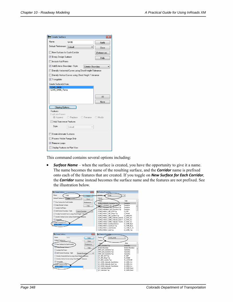
Page 348 Colorado Department of Transportation
Chapter 10 - Roadway Modeling A Practical Guide for Using InRoads XM
This command contains several options including:
Surface Name – when the surface is created, you have the opportunity to give it a name. The name becomes the name of the resulting surface, and the Corridor name is prefixed onto each of the features that are created. If you toggle on New Surface for Each Corridor, the Corridor name instead becomes the surface name and the features are not prefixed. See the illustration below.
Colorado Department of Transportation Page 349
A Practical Guide for Using InRoads XM Chapter 10 - Roadway Modeling
Empty Design Surface – if the surface has already been created, turn this option on to delete all features from the current surface before re-creating it. This ensures you don’t have left-over, duplicate or bogus features in your surface.
Add Exterior Boundary – turn this option on to automatically create an exterior boundary for the design surface(s). An exterior boundary defines the limits of triangulation. No triangles will form outside the exterior boundary, thereby eliminating bogus or bad triangles from forming in corners or concave areas. After turning this option on, specify a feature Style for the boundary, which controls it’s display properties.
Create Surfaces From – select the corridor(s) used to create the design surface(s).
Clipping Options – if running multiple corridors, use this option to determine how the surfaces will be clipped in overlapping regions. This option is used in conjunction with Target Aliasing. The corridor that uses Target Aliasing will be used to clip the other corridor.
Create Alternate Surfaces – toggle on this option if you’ve assigned template subgrade points to an alternate surface name. In addition to the finished surface, the alternate surface(s) are created.
Triangulate Surface – turn this option on to automatically triangulate surface feature points to create the triangulated network (in addition to adding the features and components to the surface). If this option is turned off, you can triangulate the surface later using the Surface > Triangulate Surface command.
Remove Loops – turn this option on to eliminate loops on features or overlapping features that may cause surface problems. Loops/overlaps occur with non-colinear alignments and can occur with secondary alignments (e.g. intersection returns).
Single corridor surface
Use the Create Surface command to create the design surface (DTM) from the selected corridor(s).
To create a design surface:
1. Select Corridor > Create Surface form the Roadway Designer menu bar or <D> the Create Surface button from the button bar.
2. Key in a Name for the surface.
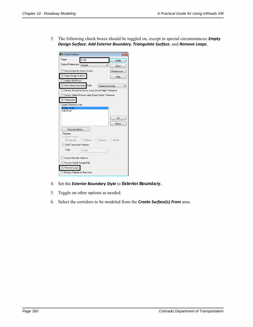
Page 350 Colorado Department of Transportation
Chapter 10 - Roadway Modeling A Practical Guide for Using InRoads XM
3. The following check boxes should be toggled on, except in special circumstances: Empty Design Surface, Add Exterior Boundary, Triangulate Surface, and Remove Loops.
4. Set the Exterior Boundary Style to Exterior Boundary.
5. Toggle on other options as needed.
6. Select the corridors to be modeled from the Create Surface(s) From area.
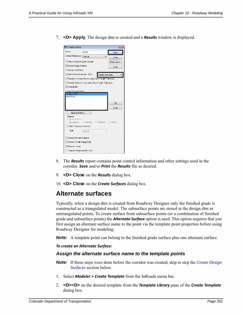
Colorado Department of Transportation Page 351
A Practical Guide for Using InRoads XM Chapter 10 - Roadway Modeling
7. <D> Apply. The design dtm is created and a Results window is displayed.
8. The Results report contains point control information and other settings used in the corridor. Save and/or Print the Results file as desired.
9. <D> Close on the Results dialog box.
10. <D> Close on the Create Surfaces dialog box.
Alternate surfaces
Typically, when a design dtm is created from Roadway Designer only the finished grade is constructed as a triangulated model. The subsurface points are stored in the design dtm as untriangulated points. To create surface from subsurface points (or a combination of finished grade and subsurface points) the Alternate Surface option is used. This option requires that you first assign an alternate surface name to the point via the template point properties before using Roadway Designer for modeling.
Note: A template point can belong to the finished grade surface plus one alternate surface.
To create an Alternate Surface:
Assign the alternate surface name to the template points
Note: If these steps were done before the corridor was created, skip to step the Create Design Surfaces section below.
1. Select Modeler > Create Template from the InRoads menu bar.
2. <D><D> on the desired template from the Template Library pane of the Create Template dialog box.
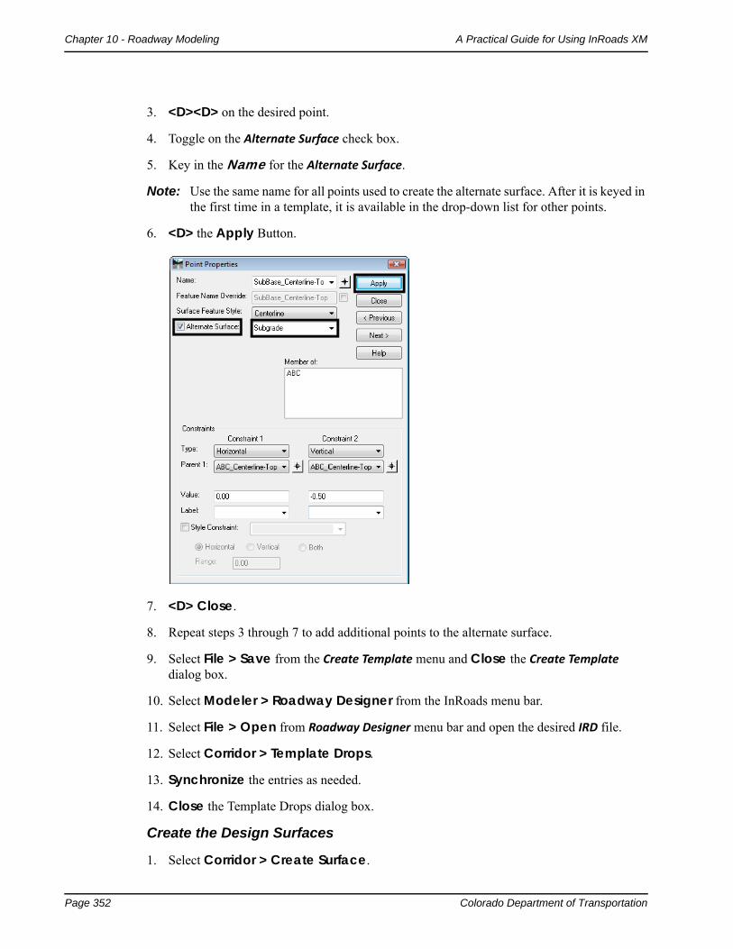
Page 352 Colorado Department of Transportation
Chapter 10 - Roadway Modeling A Practical Guide for Using InRoads XM
3. <D><D> on the desired point.
4. Toggle on the Alternate Surface check box.
5. Key in the Name for the Alternate Surface.
Note: Use the same name for all points used to create the alternate surface. After it is keyed in the first time in a template, it is available in the drop-down list for other points.
6. <D> the Apply Button.
7. <D> Close.
8. Repeat steps 3 through 7 to add additional points to the alternate surface.
9. Select File > Save from the Create Template menu and Close the Create Template dialog box.
10. Select Modeler > Roadway Designer from the InRoads menu bar.
11. Select File > Open from Roadway Designer menu bar and open the desired IRD file.
12. Select Corridor > Template Drops.
13. Synchronize the entries as needed.
14. Close the Template Drops dialog box.
Create the Design Surfaces
1. Select Corridor > Create Surface.
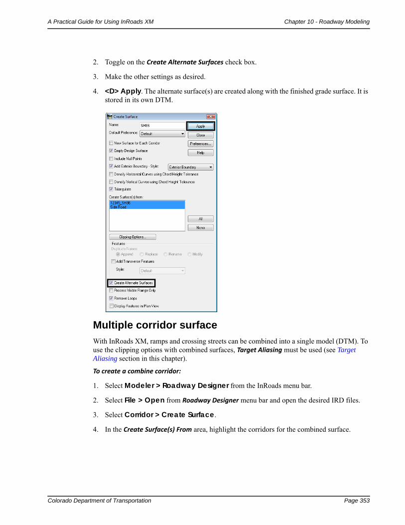
Colorado Department of Transportation Page 353
A Practical Guide for Using InRoads XM Chapter 10 - Roadway Modeling
2. Toggle on the Create Alternate Surfaces check box.
3. Make the other settings as desired.
4. <D> Apply. The alternate surface(s) are created along with the finished grade surface. It is stored in its own DTM.
Multiple corridor surface
With InRoads XM, ramps and crossing streets can be combined into a single model (DTM). To use the clipping options with combined surfaces, Target Aliasing must be used (see Target Aliasing section in this chapter).
To create a combine corridor:
1. Select Modeler > Roadway Designer from the InRoads menu bar.
2. Select File > Open from Roadway Designer menu bar and open the desired IRD files.
3. Select Corridor > Create Surface.
4. In the Create Surface(s) From area, highlight the corridors for the combined surface.
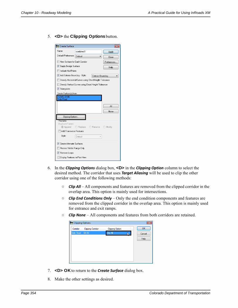
Page 354 Colorado Department of Transportation
Chapter 10 - Roadway Modeling A Practical Guide for Using InRoads XM
5. <D> the Clipping Options button.
6. In the Clipping Options dialog box, <D> in the Clipping Option column to select the desired method. The corridor that uses Target Aliasing will be used to clip the other corridor using one of the following methods:
○ Clip All – All components and features are removed from the clipped corridor in the overlap area. This option is mainly used for intersections.
○ Clip End Conditions Only – Only the end condition components and features are removed from the clipped corridor in the overlap area. This option is mainly used for entrance and exit ramps.
○ Clip None – All components and features from both corridors are retained.
7. <D> OK to return to the Create Surface dialog box.
8. Make the other settings as desired.
Colorado Department of Transportation Page 355
A Practical Guide for Using InRoads XM Chapter 10 - Roadway Modeling
9. <D> Apply. The combined surface is created.
10. <D> Close to dismiss the Create Surface dialog box.
Section Summary:♦ A design surface is composed of triangulated and untriangulated features as well as
components.
♦ Triangulated features are the linear features that result from the topmost set of points in the template and are used to create the finished grade surface.
♦ Untriangulated features are linear features that result from the points below the finished grade do not contribute to the triangulated network, unless they are specified as an alternate surface. Additional untriangulated features can come from components, such as barriers, where Component Properties are set to Exclude from Triangulation.
♦ Components are typically material definitions that can be shown on cross section and used in volume calculations. They can also be shown in plan view, where you can dynamically rotate the view to visually analyze the components in 3D.
♦ Use the Create Surface command to process your Roadway Design data to a 3D design surface.
♦ When using the Create Surface command, you have the option to create a finished grade surface from one corridor (with or without alternate surfaces) or a merged surface by combining corridors.
♦ To create an alternate surface, you must first assign an alternate surface name to the template point.
♦ A point can belong to the finished grade surface plus one alternate surface.
♦ Alternate surfaces typically are used for subgrade surfaces and you can create as many alternate surfaces as you like. Each point, however, can only be part of one alternate surface.
Chapter Summary:
Roadway modeling is the process of creating a 3D design surface or surfaces of your proposed roadway by applying roadway typical sections along a corridor and tying the template end conditions into an existing surface or other target.
Roadway Designer is the tool used to accomplish the modeling process in InRoads.
The initial design is created using CDOT design criteria and engineering data as input information to the modeling process.
Several tools allow you to refine your model by creating transitions, introducing lanes, ramps, etc.
CDOT’s superelevation design criteria is used to add superelevation to your design.
You can model, review, and edit your design in an interactive and iterative process until you have successfully refined your roadway design.
Some of the refinements you can make include modifying transitions, adjusting lift depths, adjusting sideslopes to fall within right-of-ways, replacing end conditions where needed and correcting sideslope problems at specific locations.

Page 356 Colorado Department of Transportation
Chapter 10 - Roadway Modeling A Practical Guide for Using InRoads XM
Once you model is finalized, you can create a 3D design surface from the Roadway Designer data.