Embed Size (px)
Citation preview
Part B: Operation and Maintenance
10 - 1
CHAPTER 10: ON-SITE SYSTEMS
CHAPTER 10: ON-SITE SYSTEMS
10.1 INTRODUCTION
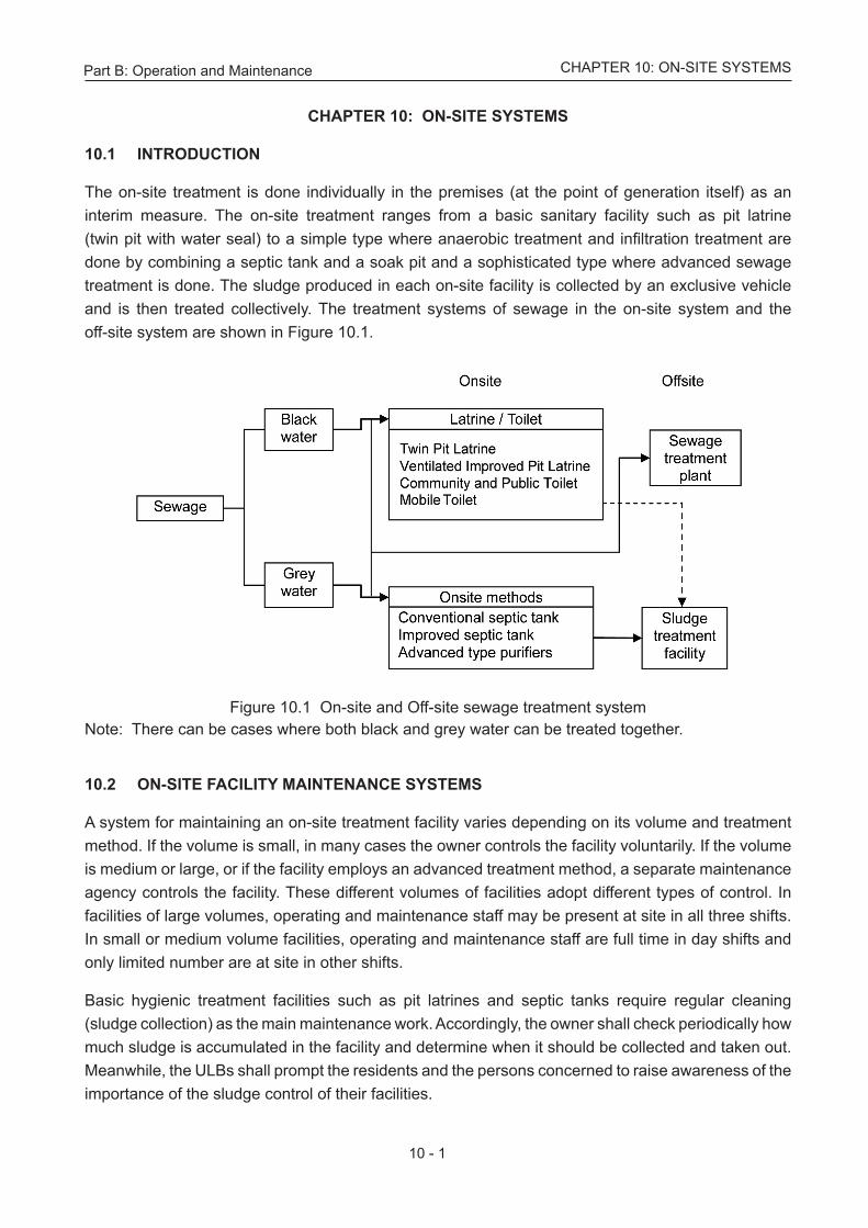
The on-site treatment is done individually in the premises (at the point of generation itself) as an interim measure. The on-site treatment ranges from a basic sanitary facility such as pit latrine (twin pit with water seal) to a simple type where anaerobic treatment and infiltration treatment are done by combining a septic tank and a soak pit and a sophisticated type where advanced sewage treatment is done. The sludge produced in each on-site facility is collected by an exclusive vehicle and is then treated collectively. The treatment systems of sewage in the on-site system and the off-site system are shown in Figure 10.1.
Figure 10.1 On-site and Off-site sewage treatment systemNote: There can be cases where both black and grey water can be treated together.
10.2 ON-SITE FACILITY MAINTENANCE SYSTEMS
A system for maintaining an on-site treatment facility varies depending on its volume and treatment method. If the volume is small, in many cases the owner controls the facility voluntarily. If the volume is medium or large, or if the facility employs an advanced treatment method, a separate maintenance agency controls the facility. These different volumes of facilities adopt different types of control. In facilities of large volumes, operating and maintenance staff may be present at site in all three shifts. In small or medium volume facilities, operating and maintenance staff are full time in day shifts and only limited number are at site in other shifts.
Basic hygienic treatment facilities such as pit latrines and septic tanks require regular cleaning (sludge collection) as the main maintenance work. Accordingly, the owner shall check periodically how much sludge is accumulated in the facility and determine when it should be collected and taken out. Meanwhile, the ULBs shall prompt the residents and the persons concerned to raise awareness of the importance of the sludge control of their facilities.
Part B: Operation and Maintenance
10 - 2
CHAPTER 10: ON-SITE SYSTEMS
More specifically, both state and municipal governments should draw up an action plan for extracting, treating, and disposing of the septage generated in these facilities in accordance with the “Septage Management Guidelines” (MoUD, 2012) and prepare the necessary budgets for implementation.
The precautions in septage management planning are listed below.
• The state and municipal governments should establish an on-site sanitation system (OSS) that conforms to relevant laws.
• Efficient management requires a database of hygienic facilities including septic tanks under control.
• Public and private agencies in charge of septage collection should establish a mechanism to ensure that the service is done promptly.
• Selecting a septage treatment method requires a survey of land use pattern and land requirements, traveling distance, pollution prevention, construction and O&M costs.
• It is necessary to disclose information about septage management to the residents and persons concerned and to conduct necessary social activities for getting their cooperation.
10.3 MAINTAINING ON-SITE FACILITIES
An on-site facility is controlled by the owner, or a habitation. Its O&M may be however by a contractor who should be familiar with the facility plan, design and specifications for the components, relevant drawings, and maintenance records. In addition, the contractor should understand how to operate, maintain, inspect, repair, and adjust the equipment, as well as how to take up their problems.
10.3.1 Inspecting and Maintaining the Treatment Unit
The advisory note on Septage Management prepared by the MoUD can be referred to regarding the inspection and maintenance of these on-site facilities.
A. Inspection The purpose of inspection is to detect an abnormal condition or failure at an early stage itself,
find out the cause and take necessary remedial measures quickly by checking the equipments for operation and the whole treatment unit for the operating status. The number of inspections may vary according to the treatment method and the volume and also the method of inspection being manual and / or remote sensing techniques.
B. Maintenance and Repair
The purpose of maintenance is to ensure that the equipment performs as defined in the specifications. If the inspection results show an abnormal condition, failure, or degradation in the performance defined in the specifications, repairs are needed. Such repairs are made by on-site staff or entrusted to a special agency.
Part B: Operation and Maintenance
10 - 3
CHAPTER 10: ON-SITE SYSTEMS
10.3.2 Cleaning
Frequent cleaning of the equipment and removing residual sludge is necessary to maintain the performance.
The contractor should keep a record of cleaning and record it in the maintenance reports.
10.3.3 Water Quality Control
Some facilities may have to be evaluated for both the quality of influent and effluent to find out the need for improving the treatment method itself.
10.3.4 Hygienic Measures including Infection Prevention
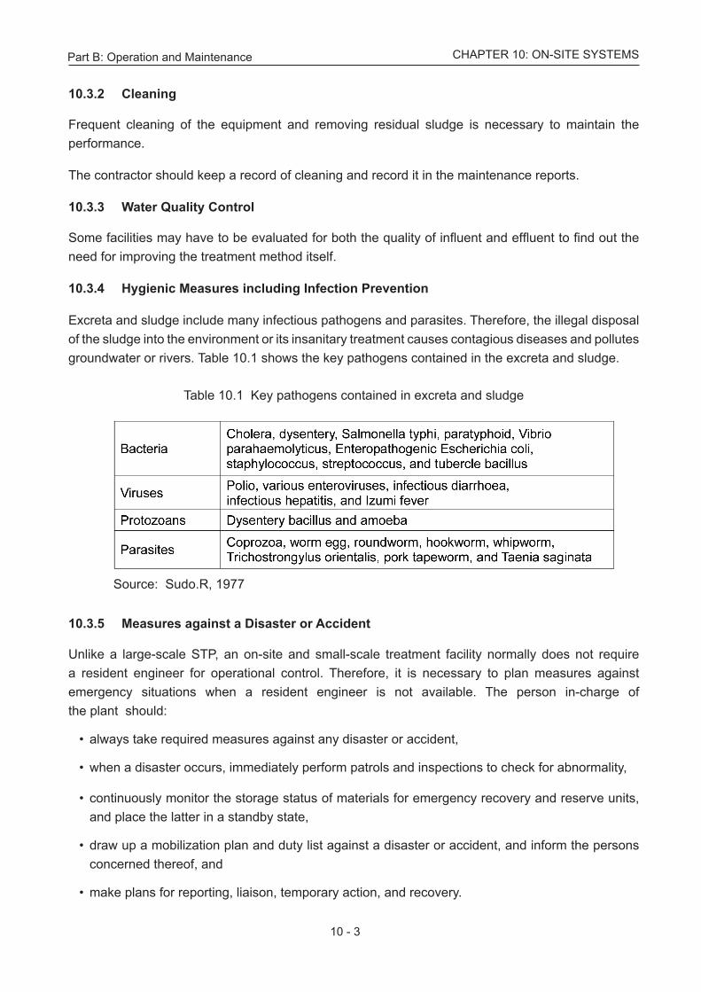
Excreta and sludge include many infectious pathogens and parasites. Therefore, the illegal disposal of the sludge into the environment or its insanitary treatment causes contagious diseases and pollutes groundwater or rivers. Table 10.1 shows the key pathogens contained in the excreta and sludge.
Table 10.1 Key pathogens contained in excreta and sludge
Source: Sudo.R, 1977
10.3.5 Measures against a Disaster or Accident
Unlike a large-scale STP, an on-site and small-scale treatment facility normally does not require a resident engineer for operational control. Therefore, it is necessary to plan measures against emergency situations when a resident engineer is not available. The person in-charge of the plant should:
• always take required measures against any disaster or accident,
• when a disaster occurs, immediately perform patrols and inspections to check for abnormality,
• continuously monitor the storage status of materials for emergency recovery and reserve units, and place the latter in a standby state,
• draw up a mobilization plan and duty list against a disaster or accident, and inform the persons concerned thereof, and
• make plans for reporting, liaison, temporary action, and recovery.
Part B: Operation and Maintenance
10 - 4
CHAPTER 10: ON-SITE SYSTEMS
10.4 LATRINE / TOILET
10.4.1 Pour Flush Water Seal Latrine
• The squatting pan should be sprinkled with a small volume, about 500 mL of water and scrubbed daily with a long handle bamboo piece or strong wood gently crushed to the shape of a brush at one end. This shall be done preferably immediately after the morning usage when the pan is wet to scour the sticky organics.
• After scrubbing, again a small volume of water should be poured and simultaneously the scrubbings can be pushed into the pit using the same make shift brush, or by other means by the householder.
• Ablution water shall be kept in a plastic container and covered with a lid and kept ready inside the latrine enclosure. The volume shall not be less than the needs of the number of persons in the household for a morning usage. For example, if a person can manage with 2 litters per usage and if there are four persons in a household, the water required is 8 litres. It will be prudent to store 10 litres of water. The mug which is used for taking the water from the stored plastic container shall be hung on the wall on a strong nail and shall not be immersed for long time inside the container because of growth of slime over the mugs.
• Storm water should not be let into the pan.
The Technology Advisory Group and World Bank have stipulated the procedure for switching from one pit to another as under.
A. Only one of the two pits is to be used at a time. After about three years when the first pit is full (the indication being back flow when flushed), the discharge from the pan should be diverted to the second pit and the first pit should not be used. The diversion of discharge to the second pit can be undertaken by the householder or, if he wishes, he can hire a private agency, which shall not get into the pit under any circumstances. After the first pit is filled and the latrine is connected to the second pit, the cover of the first pit should be removed. Thereafter soil should be filled for 150 mm depth in the pit and the cover placed in position. Where earth is not easily available or there is difficulty in removal of the pit cover, the earth could be added later when emptying the pit contents for ease of handling. The contents of the first pit shall be removed after two years by the owner or by a hired agency but no one should enter the pit. Once the cover is removed, the pit should be left free to ventilate and if it is rainy, a temporary cover shall be provided to prevent rain water entering the pit. Long handle spades, shovels or augers alone shall be used to empty the pit. The contents will then be safe for handling, dry and without any foul smell. In special cases such as flooded areas, etc., the sludge, after being taken out, should be spread out in a bed for sun drying during the non-rainy season. It can be utilized as filler in the kitchen garden or fields. When the second pit is full, the first pit should be used by diverting the discharge from second to first pit. Thus, one of the two pits is to be used alternately. The householder should keep a record when each of the two pits is put to use, disconnected and emptied; a card supplied by the local authority should be used for this purpose. The humus will become the property of the local authority. Marketing facilities may be developed for the sale and use.
Part B: Operation and Maintenance
10 - 5
CHAPTER 10: ON-SITE SYSTEMS
B. The local authority should provide free service to latrine owners, and attend to their complaints regarding construction, operation and maintenance. Groups of about 2000 latrines can be maintained by one skilled person assisted by one unskilled person. In smaller towns of less than 1500 latrines, at least one trained person should work under the guidance of a technical employee of the local authority.
However, in the beginning when the number of latrines is less than a thousand, the Junior Engineer or the Supervisor can attend to complaints by supervising and employing hired labour.
10.4.2 Public Toilet
Public toilets shall be installed in parks, along roads, and in public places. Some of these can be independent in outdoors and some installed in buildings. The users of toilets in public places are not well informed and this can result in insanitary conditions. Accordingly, the ULB shall arrange for frequent cleaning by its staff and maintain the hand-washing units regularly. If a public toilet has sewage treatment facilities, the local body shall maintain them as well. It is recommended to clean the toilet at least once a day. There should be a provision for collecting fees from the users and spending them for cleaning the toilets.
10.4.3 Mobile Toilet Mobile toilets, which can be delivered by vehicle, are temporarily used for shelters and community events. These have a storage tank in the lower part to store the sewage, which is extracted and disposed of at the appropriate time. Some mobile toilets are equipped with a cleaning water tank and manual flushing to wash the excreta. The tank capacity is limited, so it is necessary to plan a system for emptying the stored sewage and to maintain a disposal site.
The method of using common toilets applies to public and community toilets. The local authority should submit a request for regular cleaning and instruct the users not only to follow the guidelines and cooperate in conserving water.
Mobile toilets need to be kept in stock for emergency use. Therefore, the state and municipal governments should establish a network with private sectors to construct a system for arranging such toilets when an emergency occurs.
10.5 ON-SITE METHODS
10.5.1 Conventional Septic Tank / Improved Septic Tank
Septic tanks shall be designed strictly as per BIS 2470. In order to maintain the functions of septic tanks, the user should:.
• Not use, any chemicals (e.g. acid and alkaline agents) which may have an adverse effect on the functioning of the septic tank,
• Keep the tank and its surrounding area neat and clean.
Part B: Operation and Maintenance
10 - 6
CHAPTER 10: ON-SITE SYSTEMS
• Never mix oil with discharged water which will upset the digesting function of the septic tank and generate scum and foul odour. If it is unavoidable, install a gravity baffle chamber for use as an oil-water separator in the upstream of the septic tank, and
• Monitor the sludge accumulation in the septic tank at the right time to prevent its overflow.
10.5.1.1 Purifying Wastewater and Accumulating Sludge
Organic and solid substances in sewage are digested in the septic tank and converted to digester gases, scum, and digested sludge, which are gradually accumulated. Meanwhile, the sewage is purified to change to intermediate water. If the digested sludge and scum in the septic tank accumulate excessively, they partially flow out with the intermediate water, resulting in degradation in the quality of treated sewage. If the degraded treated sewage flows into the soak pit, the functioning of the soak pit is also upset. Therefore, control and regular extraction of sludge from the septic tank helps in stable performance.
The amount of sludge accumulated in the septic tank varies depending on the type, volume, and quality of sewage, the tank capacity, the foreign matter mixing ratio, and the liquid temperature. The amount of sludge can be determined by inserting a transparent vinyl pipe to the bottom of the tank, blocking the pipe tip with a finger, and pulling it out. When the amount of sludge and scum reaches about one-half of the tank depth, it is the time to extract the sludges. If the tank is large, it is recommended to perform sludge surface checks at multiple points and to find the average level. Accordingly, inspection chambers should be provided at the time of installation of the septic tank. There shall be a minimum of two chambers in each tank at opposite ends on the longer side.
10.5.1.2 Mechanical Cleaning of Septic Tank
Please refer to Appendix B.10.1 for the details on mechanical cleaning on septic tank.
10.5.1.3 Septage Management In general, the administrator requests a cleaning contractor to extract sludge from the septic tank. If a regular extraction system is introduced, the contractor visits the facilities to conduct sludge extraction work regularly. Sludge extraction is classified into two types according to the sludge accumulation status: whole and partial. These are used based on the volume of the septic tanks. For this work, equipment like a septage collection vehicle should be used and not extracting by hand. The contractor should:
• Not splash sludge on the surrounding area (e.g. the soil surface),
• Take hygienic measures if manual work is unavoidable in case,
• Extract sludge quickly, otherwise offensive odour will spread over the surrounding area, and
• Maintain a record of the work and the amount of sludge extracted.
The sludge extraction frequency is about once every two to three years, which varies depending on how the toilet is used and the tank capacity. The advisory note on septage management released by the MoUD is available in http://urbanindia.nic.in/programme/uwss/Advisory_SMUI.pdf
Part B: Operation and Maintenance
10 - 7
CHAPTER 10: ON-SITE SYSTEMS
10.5.2 Advanced Type Treatment Units
10.5.2.1 Pre-treatment Process
A. Screen Facilities
The incoming sewage contains organic as well as other inorganic foreign matter like paper, wooden pieces, silt and sand. The screening process removes the inorganic floating matter before the sewage enters the treatment unit. If screening fails for some reason, it clogs or damages the pipe, waterway, or other equipment.
i. Removing the Screened Materials
The amount of floating matter to be removed by the screen varies depending on the mesh size of the screen. If foreign matter is not removed, the captured matter increases gradually and the screen becomes clogged. In the extreme case, the sewage may overflow. Moreover, clogging stops sewage flow before the screen creating anaerobic conditions and offensive odour.
ii. Sanitary Disposal of Screened Materials
The floating matter is removed and raked into the screen bucket, and then rinsed with water for sanitary disposal to a location where dewatering equipment is installed. The area where the screen bucket is placed should be cleaned and disinfected.
B. Flow Equalization Facilities Stabilizing the function of the biological treatment process (main one) requires making the
flow rate and quality of sewage as uniform as possible and hence a flow equalization facility may be needed.
i. Control of Transfer Pump In general, the transfer pump starts, stops, or issues an alert according to the water level of the
flow equalization tank. The level at which the pump starts running varies depending on the varia-tion in inflow sewage and the margin of the flow equalization tank, but in many cases, it is set at 15 to 30 cm above the pump stop level (also known as the low water level (LWL)).
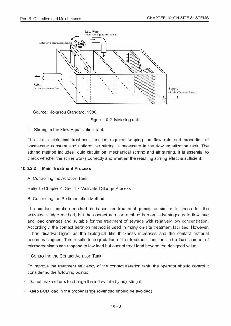
ii. Controlling the Metering Unit The metering unit receives the sewage lifted by the pump from the flow equalization tank,
supplies a given amount of sewage to the biological treatment process, and returns the remainder to the previous tank. The flow rate of the pumped sewage is adjusted by changing the height of the overflow weir. If sludge and sand accumulate in the unit or foreign matter is caught in the weir, the flow rate changes.
Therefore, sludge and sand should be removed and the unit should be cleaned regularly. The metering unit is shown in Figure 10.2. overleaf
Part B: Operation and Maintenance
10 - 8
CHAPTER 10: ON-SITE SYSTEMS
Source: Jokasou Standard, 1980
Figure 10.2 Metering unit
iii. Stirring in the Flow Equalization Tank
The stable biological treatment function requires keeping the flow rate and properties of wastewater constant and uniform, so stirring is necessary in the flow equalization tank. The stirring method includes liquid circulation, mechanical stirring and air stirring. It is essential to check whether the stirrer works correctly and whether the resulting stirring effect is sufficient.
10.5.2.2 Main Treatment Process
A. Controlling the Aeration Tank Refer to Chapter 4. Sec.4.7 “Activated Sludge Process”. B. Controlling the Sedimentation Method The contact aeration method is based on treatment principles similar to those for the
activated sludge method, but the contact aeration method is more advantageous in flow rate and load changes and suitable for the treatment of sewage with relatively low concentration. Accordingly, the contact aeration method is used in many on-site treatment facilities. However, it has disadvantages: as the biological film thickness increases and the contact material becomes clogged. This results in degradation of the treatment function and a fixed amount of microorganisms can respond to low load but cannot treat load beyond the designed value.
i. Controlling the Contact Aeration Tank
To improve the treatment efficiency of the contact aeration tank, the operator should control it considering the following points:
• Do not make efforts to change the inflow rate by adjusting it,
• Keep BOD load in the proper range (overload should be avoided)
Part B: Operation and Maintenance
10 - 9
CHAPTER 10: ON-SITE SYSTEMS
• Form biofilm that consists of appropriate microorganisms,
• Confirm the performance of the aeration in the tank (the proper dissolved oxygen concentration is not less than 2 to 3 mg/L and it can be a little higher, lower concentration degrades the treatment function),
• Pay attention to the thickness of biofilm and activate the back washing unit at the appropriate time to remove excess biofilm, and
• When the removed biofilm (sludge) increases excessively in the tank, temporarily stop aeration to settle and extract it with a pump (the sludge causes the contact material to be clogged).
ii. Controlling the Sedimentation Tank In this treatment method, the amount of microorganisms that contribute to the treatment
depends on the surface area of the contact material; therefore, it does not require adjustment of the sludge concentration in the aeration tank. Accordingly, all the sludge settled and separated in the sedimentation tank is not needed, so it should be extracted according to the volume of accumulation and feed to the sludge treatment process.
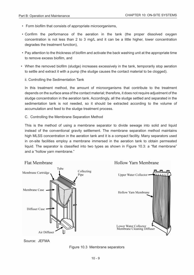
C. Controlling the Membrane Separation Method This is the method of using a membrane separator to divide sewage into solid and liquid
instead of the conventional gravity settlement. The membrane separation method maintains high MLSS concentration in the aeration tank and it is a compact facility. Many separators used in on-site facilities employ a membrane immersed in the aeration tank to obtain permeated liquid. The separator is classified into two types as shown in Figure 10.3: a “flat membrane” and a “hollow yarn membrane.”
Source: JEFMA
Figure 10.3 Membrane separators
Part B: Operation and Maintenance
10 - 10
CHAPTER 10: ON-SITE SYSTEMS
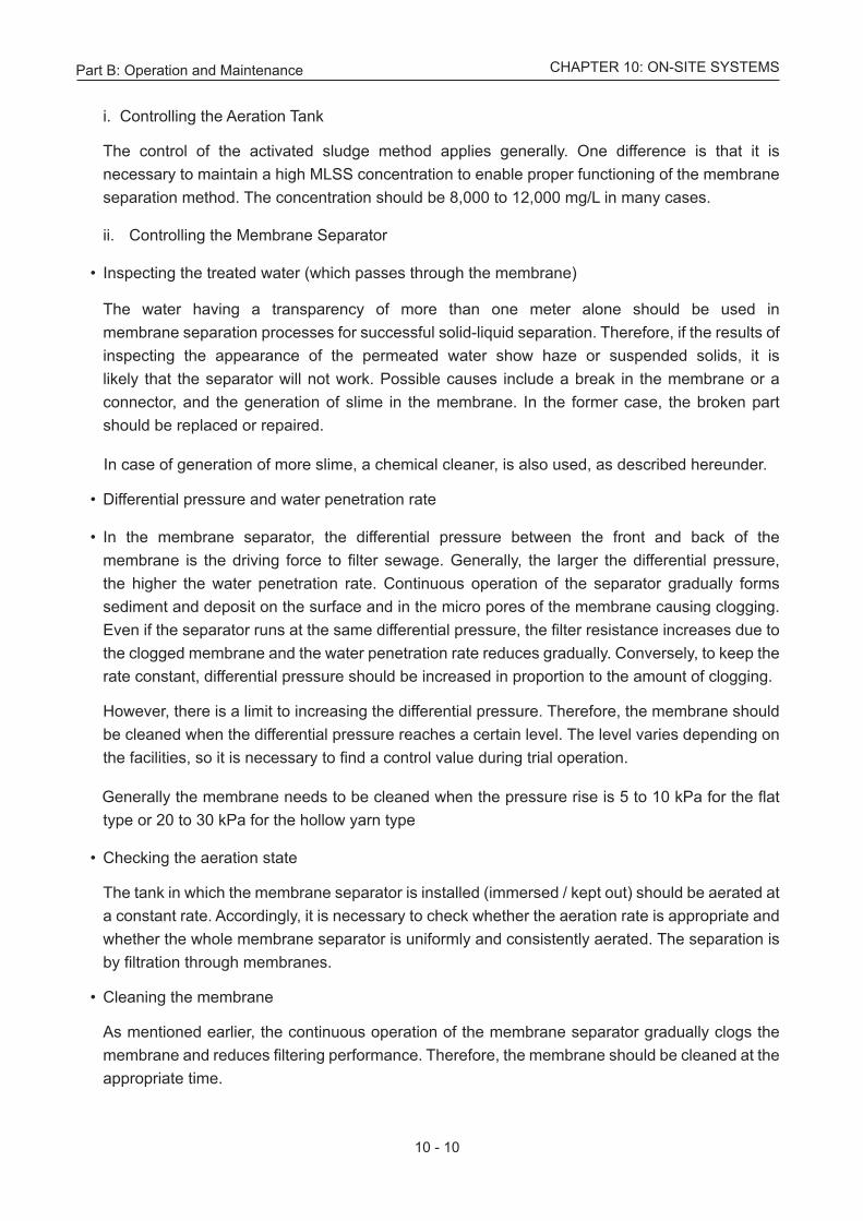
i. Controlling the Aeration Tank
The control of the activated sludge method applies generally. One difference is that it is necessary to maintain a high MLSS concentration to enable proper functioning of the membrane separation method. The concentration should be 8,000 to 12,000 mg/L in many cases.
ii. Controlling the Membrane Separator • Inspecting the treated water (which passes through the membrane)
The water having a transparency of more than one meter alone should be used in membrane separation processes for successful solid-liquid separation. Therefore, if the results of inspecting the appearance of the permeated water show haze or suspended solids, it is likely that the separator will not work. Possible causes include a break in the membrane or a connector, and the generation of slime in the membrane. In the former case, the broken part should be replaced or repaired.
In case of generation of more slime, a chemical cleaner, is also used, as described hereunder.
• Differential pressure and water penetration rate
• In the membrane separator, the differential pressure between the front and back of the membrane is the driving force to filter sewage. Generally, the larger the differential pressure, the higher the water penetration rate. Continuous operation of the separator gradually forms sediment and deposit on the surface and in the micro pores of the membrane causing clogging. Even if the separator runs at the same differential pressure, the filter resistance increases due to the clogged membrane and the water penetration rate reduces gradually. Conversely, to keep the rate constant, differential pressure should be increased in proportion to the amount of clogging.
However, there is a limit to increasing the differential pressure. Therefore, the membrane should be cleaned when the differential pressure reaches a certain level. The level varies depending on the facilities, so it is necessary to find a control value during trial operation.
Generally the membrane needs to be cleaned when the pressure rise is 5 to 10 kPa for the flat type or 20 to 30 kPa for the hollow yarn type
• Checking the aeration state
The tank in which the membrane separator is installed (immersed / kept out) should be aerated at a constant rate. Accordingly, it is necessary to check whether the aeration rate is appropriate and whether the whole membrane separator is uniformly and consistently aerated. The separation is by filtration through membranes.
• Cleaning the membrane
As mentioned earlier, the continuous operation of the membrane separator gradually clogs the membrane and reduces filtering performance. Therefore, the membrane should be cleaned at the appropriate time.
Part B: Operation and Maintenance
10 - 11
CHAPTER 10: ON-SITE SYSTEMS
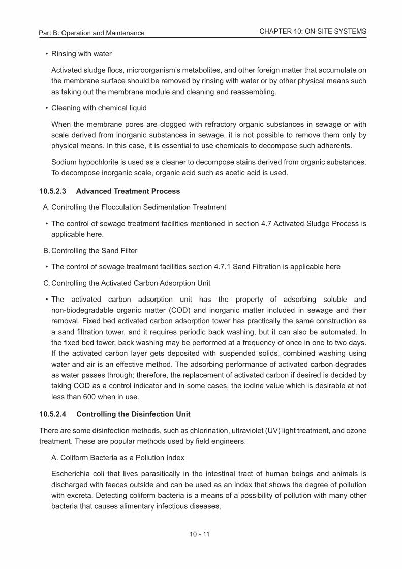
• Rinsing with water
Activated sludge flocs, microorganism’s metabolites, and other foreign matter that accumulate on the membrane surface should be removed by rinsing with water or by other physical means such as taking out the membrane module and cleaning and reassembling.
• Cleaning with chemical liquid
When the membrane pores are clogged with refractory organic substances in sewage or with scale derived from inorganic substances in sewage, it is not possible to remove them only by physical means. In this case, it is essential to use chemicals to decompose such adherents.
Sodium hypochlorite is used as a cleaner to decompose stains derived from organic substances. To decompose inorganic scale, organic acid such as acetic acid is used.
10.5.2.3 Advanced Treatment Process
A. Controlling the Flocculation Sedimentation Treatment
• The control of sewage treatment facilities mentioned in section 4.7 Activated Sludge Process is applicable here.
B. Controlling the Sand Filter
• The control of sewage treatment facilities section 4.7.1 Sand Filtration is applicable here
C. Controlling the Activated Carbon Adsorption Unit
• The activated carbon adsorption unit has the property of adsorbing soluble and non-biodegradable organic matter (COD) and inorganic matter included in sewage and their removal. Fixed bed activated carbon adsorption tower has practically the same construction as a sand filtration tower, and it requires periodic back washing, but it can also be automated. In the fixed bed tower, back washing may be performed at a frequency of once in one to two days. If the activated carbon layer gets deposited with suspended solids, combined washing using water and air is an effective method. The adsorbing performance of activated carbon degrades as water passes through; therefore, the replacement of activated carbon if desired is decided by taking COD as a control indicator and in some cases, the iodine value which is desirable at not less than 600 when in use.
10.5.2.4 Controlling the Disinfection Unit
There are some disinfection methods, such as chlorination, ultraviolet (UV) light treatment, and ozone treatment. These are popular methods used by field engineers.
A. Coliform Bacteria as a Pollution Index
Escherichia coli that lives parasitically in the intestinal tract of human beings and animals is discharged with faeces outside and can be used as an index that shows the degree of pollution with excreta. Detecting coliform bacteria is a means of a possibility of pollution with many other bacteria that causes alimentary infectious diseases.
Part B: Operation and Maintenance
10 - 12
CHAPTER 10: ON-SITE SYSTEMS
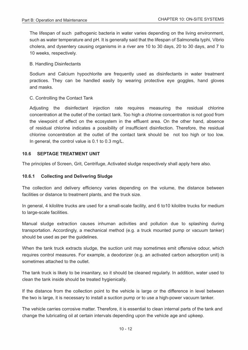
The lifespan of such pathogenic bacteria in water varies depending on the living environment, such as water temperature and pH. It is generally said that the lifespan of Salmonella typhi, Vibrio cholera, and dysentery causing organisms in a river are 10 to 30 days, 20 to 30 days, and 7 to 10 weeks, respectively.
B. Handling Disinfectants
Sodium and Calcium hypochlorite are frequently used as disinfectants in water treatment practices. They can be handled easily by wearing protective eye goggles, hand gloves and masks.
C. Controlling the Contact Tank
Adjusting the disinfectant injection rate requires measuring the residual chlorine concentration at the outlet of the contact tank. Too high a chlorine concentration is not good from the viewpoint of effect on the ecosystem in the effluent area. On the other hand, absence of residual chlorine indicates a possibility of insufficient disinfection. Therefore, the residual chlorine concentration at the outlet of the contact tank should be not too high or too low. In general, the control value is 0.1 to 0.3 mg/L.
10.6 SEPTAGE TREATMENT UNIT
The principles of Screen, Grit, Centrifuge, Activated sludge respectively shall apply here also.
10.6.1 Collecting and Delivering Sludge
The collection and delivery efficiency varies depending on the volume, the distance between facilities or distance to treatment plants, and the truck size.
In general, 4 kilolitre trucks are used for a small-scale facility, and 6 to10 kilolitre trucks for medium to large-scale facilities.
Manual sludge extraction causes inhuman activities and pollution due to splashing during transportation. Accordingly, a mechanical method (e.g. a truck mounted pump or vacuum tanker) should be used as per the guidelines.
When the tank truck extracts sludge, the suction unit may sometimes emit offensive odour, which requires control measures. For example, a deodorizer (e.g. an activated carbon adsorption unit) is sometimes attached to the outlet.
The tank truck is likely to be insanitary, so it should be cleaned regularly. In addition, water used to clean the tank inside should be treated hygienically.
If the distance from the collection point to the vehicle is large or the difference in level between the two is large, it is necessary to install a suction pump or to use a high-power vacuum tanker.
The vehicle carries corrosive matter. Therefore, it is essential to clean internal parts of the tank and change the lubricating oil at certain intervals depending upon the vehicle age and upkeep.
Part B: Operation and Maintenance
10 - 13
CHAPTER 10: ON-SITE SYSTEMS
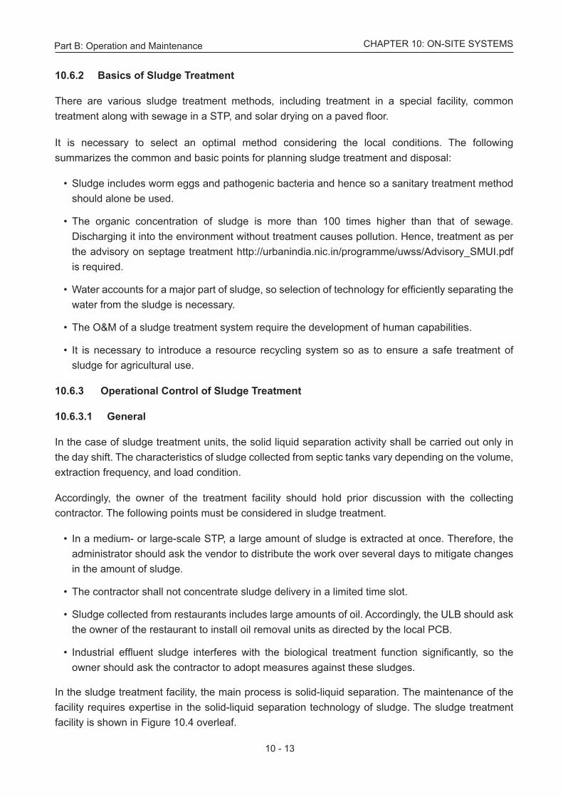
10.6.2 Basics of Sludge Treatment
There are various sludge treatment methods, including treatment in a special facility, common treatment along with sewage in a STP, and solar drying on a paved floor.
It is necessary to select an optimal method considering the local conditions. The following summarizes the common and basic points for planning sludge treatment and disposal:
• Sludge includes worm eggs and pathogenic bacteria and hence so a sanitary treatment method should alone be used.
• The organic concentration of sludge is more than 100 times higher than that of sewage. Discharging it into the environment without treatment causes pollution. Hence, treatment as per the advisory on septage treatment http://urbanindia.nic.in/programme/uwss/Advisory_SMUI.pdf is required.
• Water accounts for a major part of sludge, so selection of technology for efficiently separating the
water from the sludge is necessary.
• The O&M of a sludge treatment system require the development of human capabilities.
• It is necessary to introduce a resource recycling system so as to ensure a safe treatment of sludge for agricultural use.
10.6.3 Operational Control of Sludge Treatment
10.6.3.1 General
In the case of sludge treatment units, the solid liquid separation activity shall be carried out only in the day shift. The characteristics of sludge collected from septic tanks vary depending on the volume, extraction frequency, and load condition.
Accordingly, the owner of the treatment facility should hold prior discussion with the collecting contractor. The following points must be considered in sludge treatment.
• In a medium- or large-scale STP, a large amount of sludge is extracted at once. Therefore, the administrator should ask the vendor to distribute the work over several days to mitigate changes in the amount of sludge.
• The contractor shall not concentrate sludge delivery in a limited time slot.
• Sludge collected from restaurants includes large amounts of oil. Accordingly, the ULB should ask the owner of the restaurant to install oil removal units as directed by the local PCB.
• Industrial effluent sludge interferes with the biological treatment function significantly, so the
owner should ask the contractor to adopt measures against these sludges.
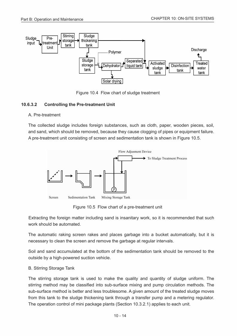
In the sludge treatment facility, the main process is solid-liquid separation. The maintenance of the facility requires expertise in the solid-liquid separation technology of sludge. The sludge treatment facility is shown in Figure 10.4 overleaf.
Part B: Operation and Maintenance
10 - 14
CHAPTER 10: ON-SITE SYSTEMS
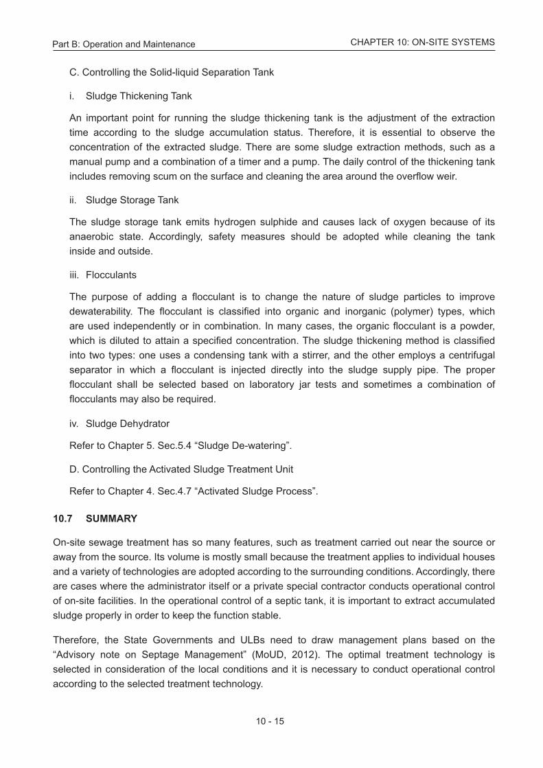
Figure 10.5 Flow chart of a pre-treatment unit
Figure 10.4 Flow chart of sludge treatment
10.6.3.2 Controlling the Pre-treatment Unit
A. Pre-treatment
The collected sludge includes foreign substances, such as cloth, paper, wooden pieces, soil, and sand, which should be removed, because they cause clogging of pipes or equipment failure. A pre-treatment unit consisting of screen and sedimentation tank is shown in Figure 10.5.
Extracting the foreign matter including sand is insanitary work, so it is recommended that such work should be automated.
The automatic raking screen rakes and places garbage into a bucket automatically, but it is
necessary to clean the screen and remove the garbage at regular intervals. Soil and sand accumulated at the bottom of the sedimentation tank should be removed to the
outside by a high-powered suction vehicle.
B. Stirring Storage Tank The stirring storage tank is used to make the quality and quantity of sludge uniform. The
stirring method may be classified into sub-surface mixing and pump circulation methods. The sub-surface method is better and less troublesome. A given amount of the treated sludge moves from this tank to the sludge thickening tank through a transfer pump and a metering regulator. The operation control of mini package plants (Section 10.3.2.1) applies to each unit.
Part B: Operation and Maintenance
10 - 15
CHAPTER 10: ON-SITE SYSTEMS
C. Controlling the Solid-liquid Separation Tank
i. Sludge Thickening Tank
An important point for running the sludge thickening tank is the adjustment of the extraction time according to the sludge accumulation status. Therefore, it is essential to observe the concentration of the extracted sludge. There are some sludge extraction methods, such as a manual pump and a combination of a timer and a pump. The daily control of the thickening tank includes removing scum on the surface and cleaning the area around the overflow weir.
ii. Sludge Storage Tank
The sludge storage tank emits hydrogen sulphide and causes lack of oxygen because of its anaerobic state. Accordingly, safety measures should be adopted while cleaning the tank inside and outside.
iii. Flocculants
The purpose of adding a flocculant is to change the nature of sludge particles to improve dewaterability. The flocculant is classified into organic and inorganic (polymer) types, which are used independently or in combination. In many cases, the organic flocculant is a powder, which is diluted to attain a specified concentration. The sludge thickening method is classified into two types: one uses a condensing tank with a stirrer, and the other employs a centrifugal separator in which a flocculant is injected directly into the sludge supply pipe. The proper flocculant shall be selected based on laboratory jar tests and sometimes a combination of flocculants may also be required.
iv. Sludge Dehydrator
Refer to Chapter 5. Sec.5.4 “Sludge De-watering”.
D. Controlling the Activated Sludge Treatment Unit
Refer to Chapter 4. Sec.4.7 “Activated Sludge Process”.
10.7 SUMMARY
On-site sewage treatment has so many features, such as treatment carried out near the source or away from the source. Its volume is mostly small because the treatment applies to individual houses and a variety of technologies are adopted according to the surrounding conditions. Accordingly, there are cases where the administrator itself or a private special contractor conducts operational control of on-site facilities. In the operational control of a septic tank, it is important to extract accumulated sludge properly in order to keep the function stable.
Therefore, the State Governments and ULBs need to draw management plans based on the “Advisory note on Septage Management” (MoUD, 2012). The optimal treatment technology is selected in consideration of the local conditions and it is necessary to conduct operational control according to the selected treatment technology.