Embed Size (px)
Citation preview
B BRIDGE DESIGN PRACTICE ● FEBRUARY 2015
Chapter 10 – Concrete Decks 10-i
CHAPTER 10
CONCRETE DECKS
TABLE OF CONTENTS
10.1 INTRODUCTION ......................................................................................................... 10-1
10.2 CONCRETE DECK TYPES ......................................................................................... 10-1
10.2.1 Cast-In-Place Concrete Decks....................................................................... 10-1
10.2.2 Precast Concrete Decks ................................................................................. 10-2
10.3 DESIGN APPROACH .................................................................................................. 10-2
10.3.1 Structural Behavior of Concrete Decks ......................................................... 10-2
10.3.2 Limit State ..................................................................................................... 10-3
10.3.3 Methods of Analysis ..................................................................................... 10-4
10.4 DESIGN CONSIDERATIONS ..................................................................................... 10-6
10.5 DETAILING CONSIDERATIONS .............................................................................. 10-6
10.5.1 Reinforcement Details ................................................................................... 10-6
10.5.2 Skewed Decks ............................................................................................... 10-7
10.5.3 Deck Drains and Access Openings ............................................................... 10-8
10.6 DESIGN EXAMPLE – REINFORCED CONCRETE BRIDGE DECK ...................... 10-8
10.6.1 Concrete Deck Data ...................................................................................... 10-8
10.6.2 Design Requirements .................................................................................... 10-9
10.6.3 Determine Minimum Deck Thickness and Cover ......................................... 10-9
10.6.4 Compute Unfactored Dead Load Moments .................................................. 10-9
10.6.5 Compute Unfactored Live Load Moments ................................................. 10-10
10.6.6 Calculate the Factored Design Moments .................................................... 10-11
10.6.7 Positive Flexure Design .............................................................................. 10-12
10.6.8 Negative Flexure Design ............................................................................. 10-14
10.6.9 Check for Crack Control under Service Limit State ................................... 10-16
10.6.10 Minimum Reinforcement ............................................................................ 10-18
NOTATION ............................................................................................................................. 10-21
REFERENCES ......................................................................................................................... 10-23

B BRIDGE DESIGN PRACTICE ● FEBRUARY 2015
Chapter 10 – Concrete Decks 10-ii
This page is intentionally left blank.
B BRIDGE DESIGN PRACTICE ● FEBRUARY 2015
Chapter 10 – Concrete Decks 10-1
CHAPTER 10
CONCRETE DECKS
10.1 INTRODUCTION
Bridge decks are an integral part of the bridge structure by providing the direct
riding surface for motor vehicles. In addition, bridge decks directly transfer load from
the moving traffic to the major load-carrying members. This chapter provides a general
description of the various concrete deck types, a discussion of the basic structural
behavior of concrete decks, and an overview of major design and detailing
considerations. Finally, a design example for a reinforced concrete bridge deck is
provided. The example illustrates bridge deck design in accordance with the
AASHTO LRFD Bridge Design Specifications (AASHTO, 2012) and the California
Amendments (Caltrans, 2014).
10.2 CONCRETE DECK TYPES
There are two main types of concrete decks, cast-in-place, and precast. The most
common type used in Caltrans is the cast-in-place reinforced concrete deck. The other
type is used depending on the various conditions like location, traffic, cost, seismicity
schedule, and aesthetics (Chen and Duan, 2014).
10.2.1 Cast-In-Place Concrete Decks
A cast-in-place concrete deck is a thin concrete slab, either using normal
reinforcement or prestressing steel, usually between 7 and 12 inches, with reinforcing
steel interspersed transversely and longitudinally throughout the slab. There are several
advantages to using a reinforced concrete deck. One of the major advantages is its
relatively low cost. Other advantages are ease of construction and extensive industry
use.
Even though cast-in-place concrete decks have advantages, there are disadvantages
using this particular type of deck, such as cracking, rebar corrosion, and tire noise. A
large cost of bridge maintenance is in maintaining the riding surface (Fu, et al., 2000).
Lack of deck crack control can lead to rebar corrosion and increased life cycle cost,
not to mention a poor riding surface for the public.
B BRIDGE DESIGN PRACTICE ● FEBRUARY 2015
Chapter 10 – Concrete Decks 10-2
10.2.2 Precast Concrete Decks
Precast concrete decks consist of either precast reinforced concrete panels or
prestressed concrete panels. These panels can either serve as the final deck surface or
as a temporary deck to allow placement of a final cast-in-place concrete deck. The
advantage of a precast concrete deck is in the acceleration of the construction schedule.
Precast panels allow for quicker placement, which, in principle, speeds up overall
bridge construction.
10.3 DESIGN APPROACH
10.3.1 Structural Behavior of Concrete Decks
It is accepted and widely known that the primary structural behavior of a concrete
deck is not pure flexure, but a complex behavior known as internal arching. Concrete
slabs behave quite differently than concrete beams under a given load. Research has
shown that when a concrete slab starts to crack, the load is initially resisted by a
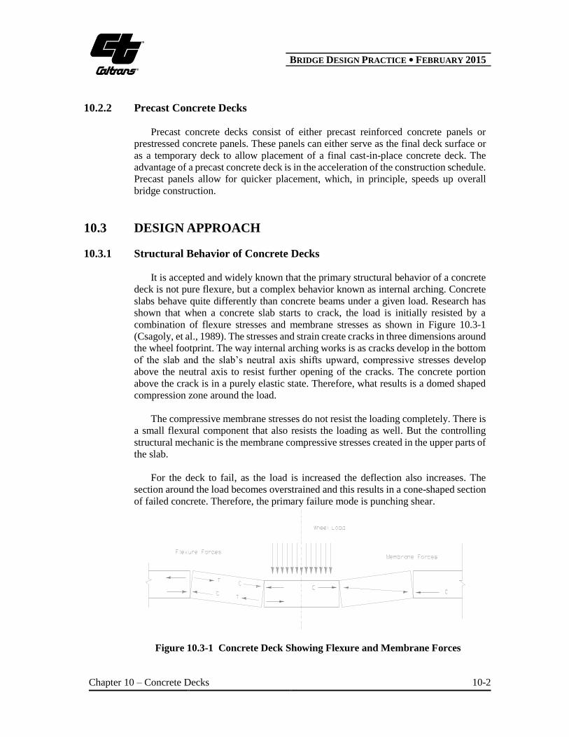
combination of flexure stresses and membrane stresses as shown in Figure 10.3-1
(Csagoly, et al., 1989). The stresses and strain create cracks in three dimensions around
the wheel footprint. The way internal arching works is as cracks develop in the bottom
of the slab and the slab’s neutral axis shifts upward, compressive stresses develop
above the neutral axis to resist further opening of the cracks. The concrete portion
above the crack is in a purely elastic state. Therefore, what results is a domed shaped
compression zone around the load.
The compressive membrane stresses do not resist the loading completely. There is
a small flexural component that also resists the loading as well. But the controlling
structural mechanic is the membrane compressive stresses created in the upper parts of
the slab.
For the deck to fail, as the load is increased the deflection also increases. The
section around the load becomes overstrained and this results in a cone-shaped section
of failed concrete. Therefore, the primary failure mode is punching shear.
Figure 10.3-1 Concrete Deck Showing Flexure and Membrane Forces
B BRIDGE DESIGN PRACTICE ● FEBRUARY 2015
Chapter 10 – Concrete Decks 10-3
10.3.2 Limit State
10.3.2.1 Service Limit State
Concrete decks are designed to meet the requirements for Service I limit state
(AASHTO Article 9.5.2). Service limit state is used to control excessive deformation
and cracking. According to the California amendment (CA Article 9.5.2), deck slabs
shall be designed for Class 2 exposure, therefore,
750.e (AASHTO Article 5.7.3.4)
10.3.2.2 Strength Limit State
Concrete decks must be designed for Strength I limit state. Because concrete deck
slabs are usually designed as tension-controlled reinforced concrete components, the
resistance factor is 90. (AASHTO Article 5.5.4.2). Strength II limit state typically
is not checked for deck designs. The permit vehicle axle load does not typically control
deck design (CA Article C3.6.1.3.3).
10.3.2.3 Extreme Event Limit State
Most bridge decks include an overhang with a concrete barrier attached. Therefore,
the deck overhang has to be designed to meet the requirements for Extreme Event II.
The AASHTO (2012) requires bridge deck overhangs to be designed for the following
cases (AASHTO Appendix A13.4):
Design Case 1: The transverse and longitudinal forces specified in AASHTO
Appendix A13.2 - Extreme Event Load Combination II limit state.
Design Case 2: The vertical forces specified in AASHTO Appendix A13.2 -
Extreme Event Load Combination II limit state.
Design Case 3: The loads, specified in AASHTO Article 3.6.1, that occupy the
overhang- Load Combination Strength I limit state.
10.3.2.4 Fatigue Limit State
Concrete decks supported by multi-girder systems are not required to be
investigated for fatigue (AASHTO Article 9.5.3).

B BRIDGE DESIGN PRACTICE ● FEBRUARY 2015
Chapter 10 – Concrete Decks 10-4
10.3.3 Methods of Analysis
10.3.3.1 Approximate Method of Analysis
Caltrans traditionally designs concrete bridge decks as transverse strips as a flexure
member. This method is called the Approximate Method of Analysis (AASHTO
Article 4.6.2.1). The concrete deck is assumed to be transverse slab strips, which is
supported by the girders. To simplify the design, it is assumed that the girders are rigid
supports. The AASHTO specifications allow the maximum positive moment and the
maximum negative moment to apply for all positive moment regions and all negative
moment regions in the slab, respectively.
The width of an equivalent strip (interior strip) is dependent on the type of deck
used, the primary direction of the strip relative to the direction of traffic, and the sign
of the moment. AASHTO Table 4.6.2.1.3-1 only applies for interior strips and not for
overhangs.
10.3.3.2 Refined Methods of Analysis
The Refined Methods of Analysis (AASHTO Article 4.6.3) as listed in AASHTO
4.4 are acceptable methods for analyzing concrete bridge decks. But these various
methods are not typically used to analyze a standard bridge deck. A refined analysis
method would be better suited for a more complex deck slab structure, which would
require a more detailed analysis.
10.3.3.3 Empirical Method of Analysis
Empirical Design (AASHTO Article 9.7.1) is a method of deck slab design based
on the concept of internal arching action within concrete slabs. But, until further
durability testing of this design method is completed, the empirical design method is
not permitted for concrete bridge deck design in California (CA Article 9.7.2.2).
B BRIDGE DESIGN PRACTICE ● FEBRUARY 2015
Chapter 10 – Concrete Decks 10-5
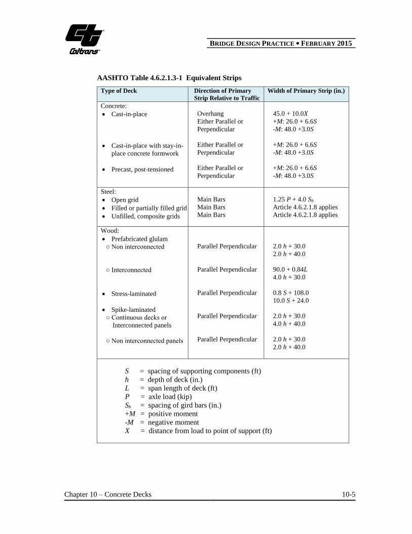
AASHTO Table 4.6.2.1.3-1 Equivalent Strips
Type of Deck Direction of Primary
Strip Relative to Traffic
Width of Primary Strip (in.)
Concrete:
Cast-in-place
Cast-in-place with stay-in-
place concrete formwork
Precast, post-tensioned
Overhang
Either Parallel or
Perpendicular
Either Parallel or
Perpendicular
Either Parallel or
Perpendicular
45.0 + 10.0X
+M: 26.0 + 6.6S
-M: 48.0 +3.0S
+M: 26.0 + 6.6S
-M: 48.0 +3.0S
+M: 26.0 + 6.6S
-M: 48.0 +3.0S
Steel:
Open grid
Filled or partially filled grid
Unfilled, composite grids
Main Bars
Main Bars
Main Bars
1.25 P + 4.0 Sb
Article 4.6.2.1.8 applies
Article 4.6.2.1.8 applies
Wood:
Prefabricated glulam
○ Non interconnected
○ Interconnected
Stress-laminated
Spike-laminated
○ Continuous decks or
Interconnected panels
○ Non interconnected panels
Parallel Perpendicular
Parallel Perpendicular
Parallel Perpendicular
Parallel Perpendicular
Parallel Perpendicular
2.0 h + 30.0
2.0 h + 40.0
90.0 + 0.84L
4.0 h + 30.0
0.8 S + 108.0
10.0 S + 24.0
2.0 h + 30.0
4.0 h + 40.0
2.0 h + 30.0
2.0 h + 40.0
S = spacing of supporting components (ft)
h = depth of deck (in.)
L = span length of deck (ft)
P = axle load (kip)
Sb = spacing of gird bars (in.)
+M = positive moment
-M = negative moment
X = distance from load to point of support (ft)
B BRIDGE DESIGN PRACTICE ● FEBRUARY 2015
Chapter 10 – Concrete Decks 10-6
10.4 DESIGN CONSIDERATIONS
Concrete decks are primarily designed for flexure in the transverse direction;
therefore, the spacing of adjacent girders is important. AASHTO Table A4-1 provides
a listing of design moments for “S” (girder spacing) values between 4 ft and 15 ft.
When “S” exceeds 15 ft, special design is required.
The designer needs to consider required deck thickness. According to CA 9.7.1.1
(Caltrans, 2014), the minimum deck thickness is to “conform to the deck design
standards developed by Caltrans”. For the typical deck slab, MTD 10-20 (Caltrans,
2008) provides the minimum deck slab thicknesses and reinforcement schedule for
various girder types. The typical deck slab thickness varies from 7 in. to 10 3/8 in.
depending on the girder type and spacing.
The minimum concrete cover is determined in accordance with CA 5.12.3.
Extreme environments can have a negative effect on the service life of a concrete deck
slab. Corrosion of the reinforcing steel should be a major concern when designing a
bridge deck in an extreme environment. There are various ways for the designer to
protect against corrosion of the bridge deck. See MTD 10-5 (Caltrans, 2010) for more
information on protecting against corrosion.
For design purposes, the minimum compressive concrete strength 'cf =3.6 ksi shall
be used for reinforced concrete (CA Article 5.4.2.1).
10.5 DETAILING CONSIDERATIONS
10.5.1 Reinforcement Details
Typical reinforced concrete decks are detailed as part of the superstructure typical
section. The designer should use MTD 10-20 (Caltrans, 2008) for required minimum
reinforcement and Standard Plan B0-5 for transverse reinforcement spacing diagrams.
It is important to check main longitudinal reinforcement spacing and cover to ensure
reinforcing steel can fit within slab thickness.
For variable width girders it is important for the designer to specify reinforcement
spacing and type that differs from the standard superstructure bay. See BDD 8-34
(Caltrans, 1986) for more information on acceptable reinforcement detailing in
variable bays. Limits of epoxy-coated reinforcement shall also be specified.
B BRIDGE DESIGN PRACTICE ● FEBRUARY 2015
Chapter 10 – Concrete Decks 10-7
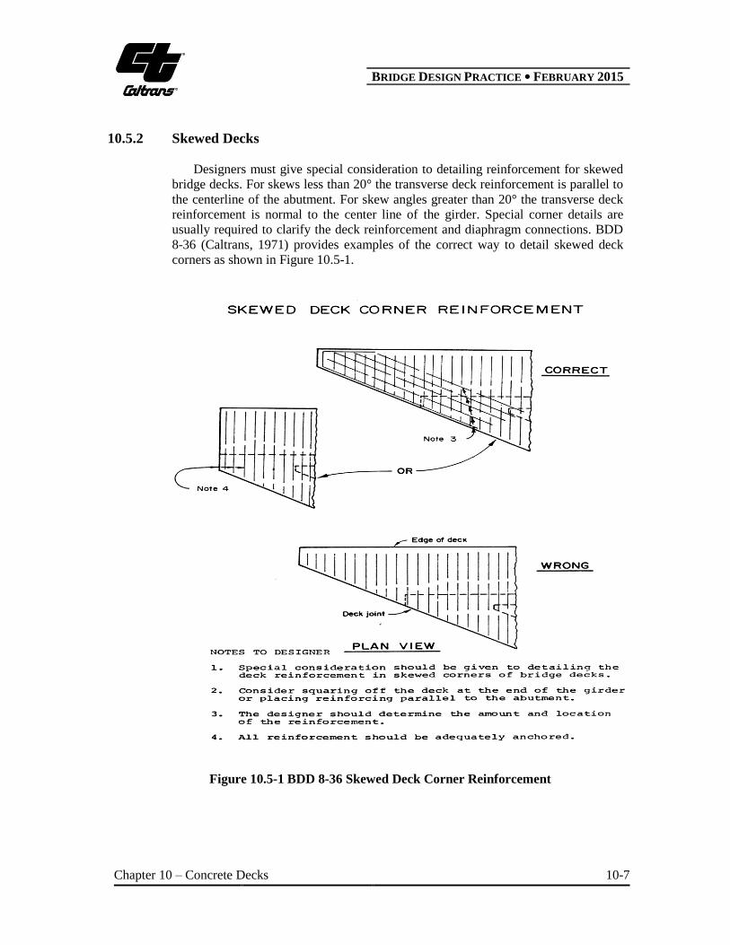
10.5.2 Skewed Decks
Designers must give special consideration to detailing reinforcement for skewed
bridge decks. For skews less than 20° the transverse deck reinforcement is parallel to
the centerline of the abutment. For skew angles greater than 20° the transverse deck
reinforcement is normal to the center line of the girder. Special corner details are
usually required to clarify the deck reinforcement and diaphragm connections. BDD
8-36 (Caltrans, 1971) provides examples of the correct way to detail skewed deck
corners as shown in Figure 10.5-1.
Figure 10.5-1 BDD 8-36 Skewed Deck Corner Reinforcement
B BRIDGE DESIGN PRACTICE ● FEBRUARY 2015
Chapter 10 – Concrete Decks 10-8
10.5.3 Deck Drains and Access Openings
After determination of the type of deck drain and the deck drain location, it is
important to ensure that the drain fits the location specified. Depending on the type of
deck drain used it may be necessary to provide additional reinforcement to secure the
drain assembly in place.
Deck openings are discouraged. Soffit openings are the preferred method to
provide access into the bridge bays. If deck openings are used then Standard Plan
B7-11 Utility Details provide additional reinforcement for openings.
10.6 DESIGN EXAMPLE – REINFORCED CONCRETE BRIDGE
DECK
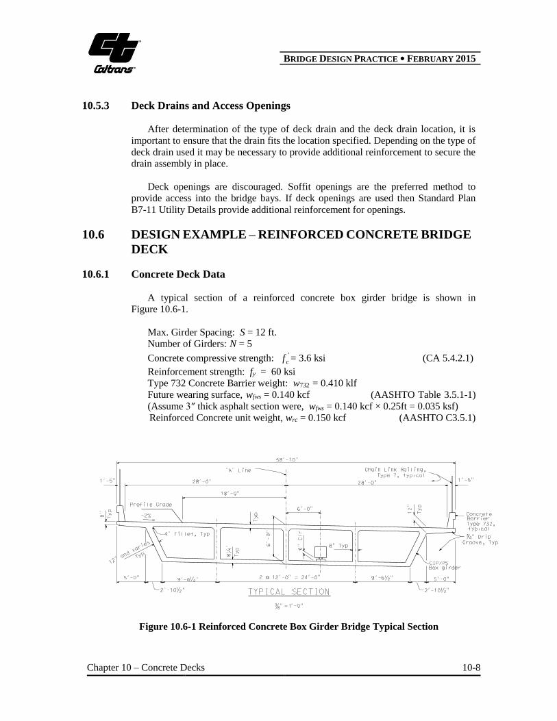
10.6.1 Concrete Deck Data
A typical section of a reinforced concrete box girder bridge is shown in
Figure 10.6-1.
Max. Girder Spacing: S = 12 ft.
Number of Girders: N = 5
Concrete compressive strength: 'cf = 3.6 ksi (CA 5.4.2.1)
Reinforcement strength: fy = 60 ksi
Type 732 Concrete Barrier weight: w732 = 0.410 klf
Future wearing surface, wfws = 0.140 kcf (AASHTO Table 3.5.1-1)
(Assume 3″ thick asphalt section were, wfws = 0.140 kcf × 0.25ft = 0.035 ksf)
Reinforced Concrete unit weight, wrc = 0.150 kcf (AASHTO C3.5.1)
Figure 10.6-1 Reinforced Concrete Box Girder Bridge Typical Section
B BRIDGE DESIGN PRACTICE ● FEBRUARY 2015
Chapter 10 – Concrete Decks 10-9
10.6.2 Design Requirements
Design the concrete bridge deck supported by the girders using the Approximate
Method of Analysis (AASHTO Article 4.6.2) in accordance with the AASHTO LRFD
Bridge Design Specifications (AASHTO, 2012) with the California Amendments
(Caltrans, 2014).
10.6.3 Determine Minimum Deck Thickness and Cover
According to CA Article 9.7.1.1 (Caltrans, 2014), the minimum deck thickness
must conform to the deck design standards specified by MTD 10-20 (Caltrans, 2008).
The minimum deck thickness varies depending on the girder type and the centerline to
centerline spacing. Therefore, for a reinforced concrete box girder bridge,
S = 12.00 ft assumes a minimum thickness t = 9 1/8 in.
The minimum concrete cover is determined according to CA Table 5.12.3-1. For
the top surface of the bridge deck in a non-corrosive atmosphere the minimum cover
is specified as:
Deck Top Cover: Ctop = 2.0 in.
The minimum cover specified for the bottom surface of the deck slab is:
Deck Bottom Cover: Cbottom = 1.0 in.
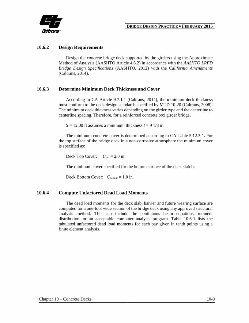
10.6.4 Compute Unfactored Dead Load Moments
The dead load moments for the deck slab, barrier and future wearing surface are
computed for a one-foot wide section of the bridge deck using any approved structural
analysis method. This can include the continuous beam equations, moment
distribution, or an acceptable computer analysis program. Table 10.6-1 lists the
tabulated unfactored dead load moments for each bay given in tenth points using a
finite element analysis.
B BRIDGE DESIGN PRACTICE ● FEBRUARY 2015
Chapter 10 – Concrete Decks 10-10
Table 10.6-1 Unfactored Dead Load Moments
Distance
Slab Dead Load-DC1
(kip-ft/ft)
Barrier Load-DC2
(kip-ft/ft)
Future Wearing Surface Dead
Load-DW (kip-ft/ft)
Bay 1 Bay 2 Bay 3 Bay 4 Bay 1 Bay 2 Bay 3 Bay 4 Bay 1 Bay 2 Bay 3 Bay 4
0 -1.62 -1.30 -1.40 -1.30 -1.81 0.51 -0.25 0.51 -0.26 -0.46 -0.40 -0.46
0.1 -0.84 -0.57 -0.65 -0.60 -1.56 0.43 -0.18 0.28 -0.05 -0.23 -0.18 -0.22
0.2 -0.24 -0.01 -0.07 -0.05 -1.35 0.36 -0.10 0.05 0.11 -0.05 -0.01 -0.02
0.3 0.21 0.40 0.35 0.33 -1.11 0.28 -0.02 -0.18 0.21 0.08 0.11 0.13
0.4 0.05 0.63 0.61 0.55 -0.88 0.21 0.05 -0.42 0.27 0.16 0.18 0.22
0.5 0.60 0.70 0.70 0.60 -0.65 0.13 0.13 -0.65 0.27 0.20 0.20 0.27
0.6 0.55 0.61 0.63 0.48 -0.42 0.05 0.21 -0.88 0.22 0.18 0.16 0.27
0.7 0.33 0.35 0.40 0.21 -0.18 -0.02 0.28 -1.11 0.13 0.11 0.08 0.21
0.8 -0.05 -0.07 -0.01 -0.24 0.05 -0.10 0.36 -1.35 -0.02 -0.01 -0.05 0.11
0.9 -0.60 -0.65 -0.57 -0.84 0.28 -0.18 0.43 -1.56 -0.22 -0.18 -0.23 -0.05
1 -1.30 -1.40 -1.30 -1.62 0.51 -0.25 0.51 -1.81 -0.46 -0.40 -0.46 -0.26
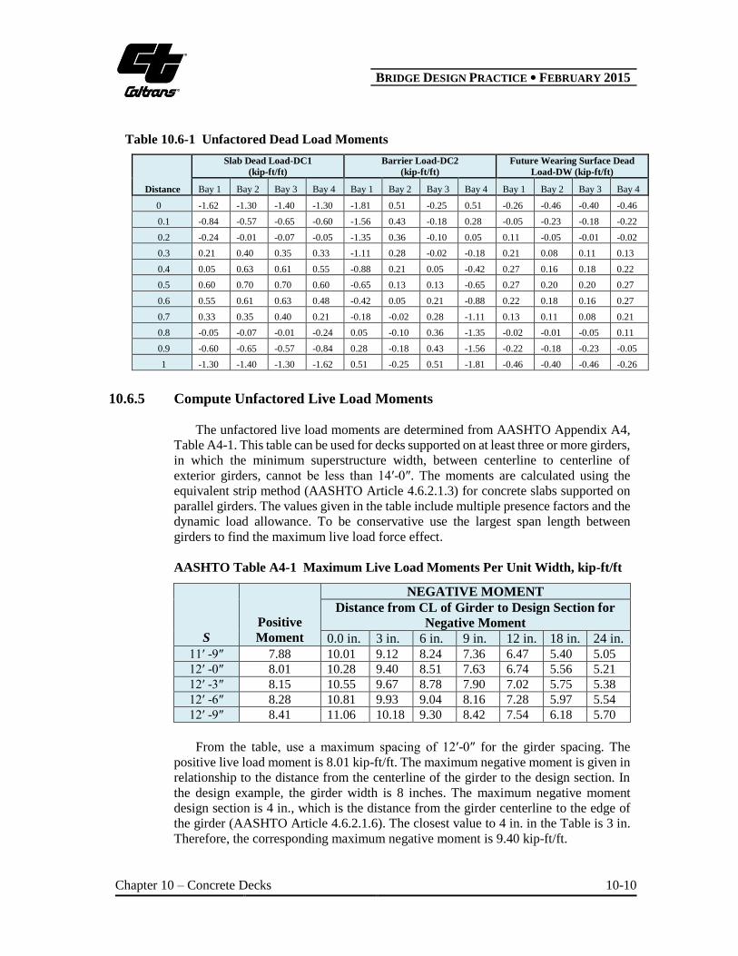
10.6.5 Compute Unfactored Live Load Moments
The unfactored live load moments are determined from AASHTO Appendix A4,
Table A4-1. This table can be used for decks supported on at least three or more girders,
in which the minimum superstructure width, between centerline to centerline of
exterior girders, cannot be less than 14′-0″. The moments are calculated using the
equivalent strip method (AASHTO Article 4.6.2.1.3) for concrete slabs supported on
parallel girders. The values given in the table include multiple presence factors and the
dynamic load allowance. To be conservative use the largest span length between
girders to find the maximum live load force effect.
AASHTO Table A4-1 Maximum Live Load Moments Per Unit Width, kip-ft/ft
S
Positive
Moment
NEGATIVE MOMENT
Distance from CL of Girder to Design Section for
Negative Moment
0.0 in. 3 in. 6 in. 9 in. 12 in. 18 in. 24 in.
11′ -9″ 7.88 10.01 9.12 8.24 7.36 6.47 5.40 5.05
12′ -0″ 8.01 10.28 9.40 8.51 7.63 6.74 5.56 5.21
12′ -3″ 8.15 10.55 9.67 8.78 7.90 7.02 5.75 5.38
12′ -6″ 8.28 10.81 9.93 9.04 8.16 7.28 5.97 5.54
12′ -9″ 8.41 11.06 10.18 9.30 8.42 7.54 6.18 5.70
From the table, use a maximum spacing of 12′-0″ for the girder spacing. The
positive live load moment is 8.01 kip-ft/ft. The maximum negative moment is given in
relationship to the distance from the centerline of the girder to the design section. In
the design example, the girder width is 8 inches. The maximum negative moment
design section is 4 in., which is the distance from the girder centerline to the edge of
the girder (AASHTO Article 4.6.2.1.6). The closest value to 4 in. in the Table is 3 in.
Therefore, the corresponding maximum negative moment is 9.40 kip-ft/ft.
B BRIDGE DESIGN PRACTICE ● FEBRUARY 2015
Chapter 10 – Concrete Decks 10-11
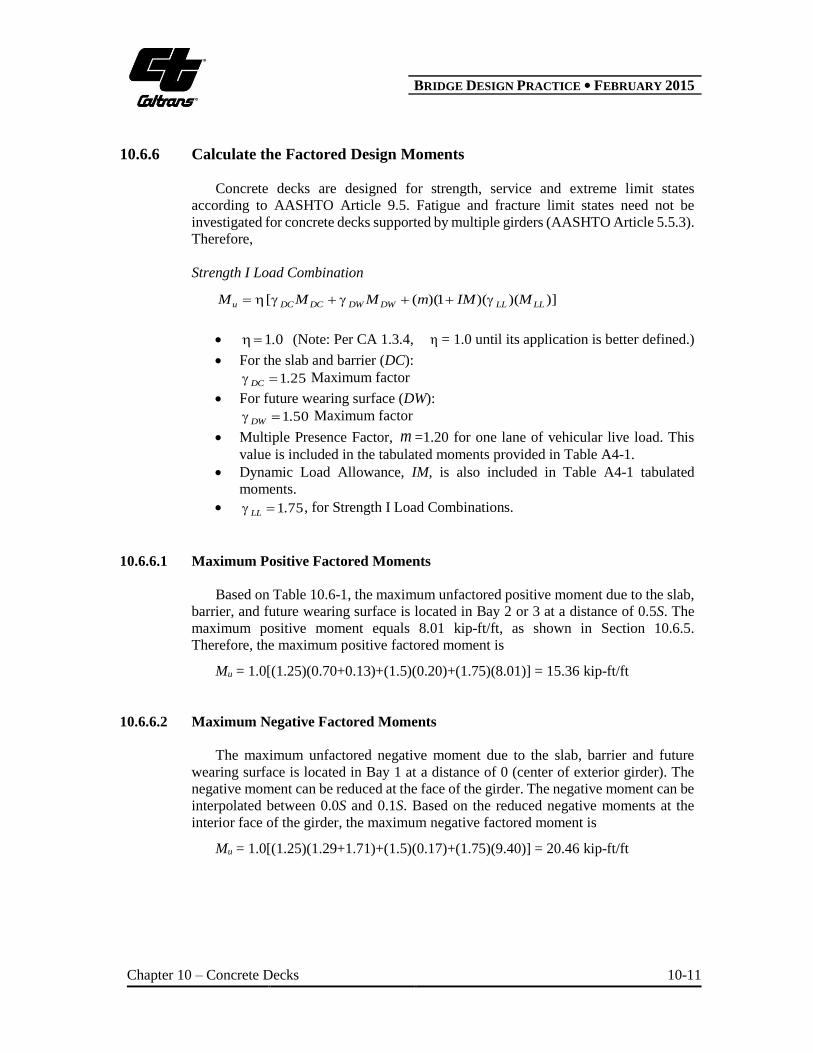
10.6.6 Calculate the Factored Design Moments
Concrete decks are designed for strength, service and extreme limit states
according to AASHTO Article 9.5. Fatigue and fracture limit states need not be
investigated for concrete decks supported by multiple girders (AASHTO Article 5.5.3).
Therefore,
Strength I Load Combination
)])()(1)(([ LLLLDWDWDCDCu MIMmMMM
01. (Note: Per CA 1.3.4, η = 1.0 until its application is better defined.)
For the slab and barrier (DC):
251.DC Maximum factor
For future wearing surface (DW):
501.DW Maximum factor
Multiple Presence Factor, m =1.20 for one lane of vehicular live load. This
value is included in the tabulated moments provided in Table A4-1.
Dynamic Load Allowance, IM, is also included in Table A4-1 tabulated
moments.
751.LL , for Strength I Load Combinations.
10.6.6.1 Maximum Positive Factored Moments
Based on Table 10.6-1, the maximum unfactored positive moment due to the slab,
barrier, and future wearing surface is located in Bay 2 or 3 at a distance of 0.5S. The
maximum positive moment equals 8.01 kip-ft/ft, as shown in Section 10.6.5.
Therefore, the maximum positive factored moment is
Mu = 1.0[(1.25)(0.70+0.13)+(1.5)(0.20)+(1.75)(8.01)] = 15.36 kip-ft/ft
10.6.6.2 Maximum Negative Factored Moments
The maximum unfactored negative moment due to the slab, barrier and future
wearing surface is located in Bay 1 at a distance of 0 (center of exterior girder). The
negative moment can be reduced at the face of the girder. The negative moment can be
interpolated between 0.0S and 0.1S. Based on the reduced negative moments at the
interior face of the girder, the maximum negative factored moment is
Mu = 1.0[(1.25)(1.29+1.71)+(1.5)(0.17)+(1.75)(9.40)] = 20.46 kip-ft/ft
B BRIDGE DESIGN PRACTICE ● FEBRUARY 2015
Chapter 10 – Concrete Decks 10-12
10.6.7 Positive Flexure Design
To design for the maximum positive moment, first, assume an initial bar size. From
this initial bar size, the required area of steel can be calculated. Then the reinforcement
spacing can be determined. For this example the assumed initial reinforcing steel size
is #5.
For a #5-bar,
Bar area = 0.31 in2
Bar diameter = 0.625 in.
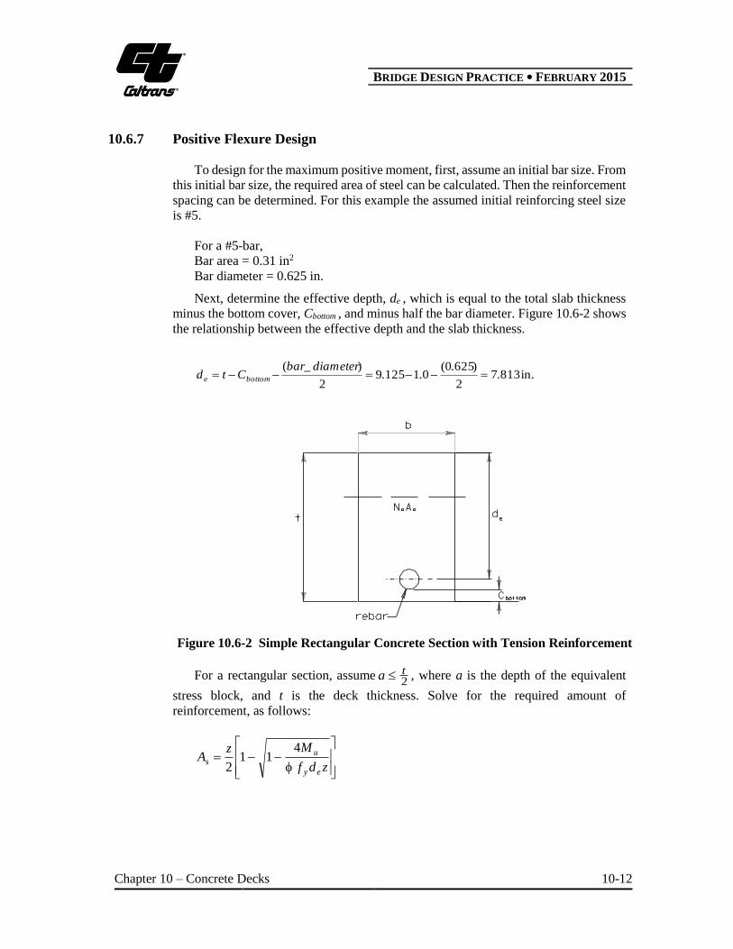
Next, determine the effective depth, de , which is equal to the total slab thickness
minus the bottom cover, Cbottom , and minus half the bar diameter. Figure 10.6-2 shows
the relationship between the effective depth and the slab thickness.
in.81372
)6250(011259
2
)(.
...
diameter_barCtd bottome
Figure 10.6-2 Simple Rectangular Concrete Section with Tension Reinforcement
For a rectangular section, assume2ta , where a is the depth of the equivalent
stress block, and t is the deck thickness. Solve for the required amount of
reinforcement, as follows:
zdf
MzA
ey
us
411
2
B BRIDGE DESIGN PRACTICE ● FEBRUARY 2015
Chapter 10 – Concrete Decks 10-13
where,
y
ec
f
bdfz
'7.1
90. (Assume tension control) (AASHTO 5.5.4.2.1) b = 12 in.
Therefore,
z = 9.56 in.2
As = 0.459 in.2
Check 2
ta ,
in.56.4in75.0'85.0
bf
fAa
c
ys
Next, determine the required bar spacing,
in.10.8459.0
31.012_12_
sA
areabarspacingbar use, 8 in. spacing for #5 bar.
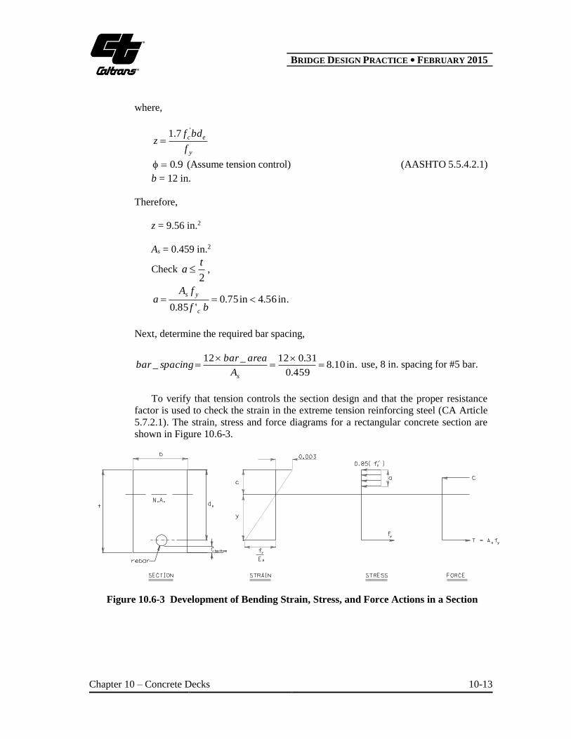
To verify that tension controls the section design and that the proper resistance
factor is used to check the strain in the extreme tension reinforcing steel (CA Article
5.7.2.1). The strain, stress and force diagrams for a rectangular concrete section are
shown in Figure 10.6-3.
Figure 10.6-3 Development of Bending Strain, Stress, and Force Actions in a Section
B BRIDGE DESIGN PRACTICE ● FEBRUARY 2015
Chapter 10 – Concrete Decks 10-14
Calculate the tension force and the area of concrete.
2in.46508
)310(1285 .
.A"@# s
kips9.27)60(465.0 ys fAT
2in.129)63(850
927
850)850( .
..
.
f.
TAf.AT
'c
c'cc
Determine concrete compression block depth, a
in.76.012
12.9
b
Aa c
Determine c from the equation ca1
890850
760
1
..
.ac
Check if steel yields,
00400230)0030(890
)8908137()0030( ...
.
...
c
ys
The steel yields and the section is tension controlled, therefore, the proper
resistance factor was used.
Finally, check maximum spacing for primary reinforcement (AASHTO Article
5.10.3.2). The spacing of the slab reinforcement shall not exceed 1.5 times the
thickness of the slab or 18.0 in. In this case the maximum spacing equals 8.0 in., which
is less than either case.
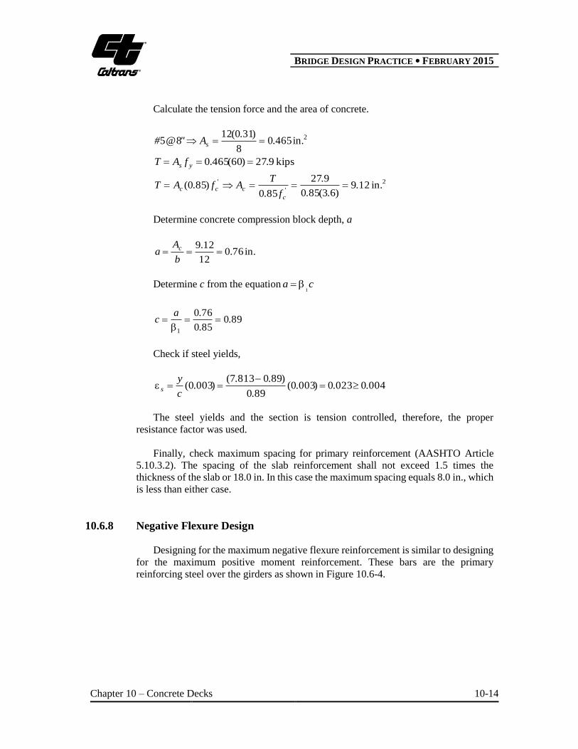
10.6.8 Negative Flexure Design
Designing for the maximum negative flexure reinforcement is similar to designing
for the maximum positive moment reinforcement. These bars are the primary
reinforcing steel over the girders as shown in Figure 10.6-4.
B BRIDGE DESIGN PRACTICE ● FEBRUARY 2015
Chapter 10 – Concrete Decks 10-15
Figure 10.6-4 Negative Reinforcement over a Typical Girder
Assuming #6 bar size.
Bar area = 0.44 in.2
Bar diameter = 0.750 in.
The effective depth, de , for the negative moment is equal to the total slab thickness
minus the top cover, Ctop , and half the bar diameter.
in.7562
)7500(021259
2
)(.
...
diameter_barCtd tope
Based on the maximum negative moment
z = 8.262 in.2
As = 0.840 in.2
Check2
ta ,
in.56.4in.209.1'85.0
bf
fAa
c
ys
Required bar spacing is
2in.14.7740.0
44.012_12_
sA
areabarspacingbar , use 7.0 in. spacing.
B BRIDGE DESIGN PRACTICE ● FEBRUARY 2015
Chapter 10 – Concrete Decks 10-16
Verify that tension controls the section design and that the proper resistance factor
is used to check the strain in the extreme tension reinforcing steel (CA Article 5.7.2.1).
Finally, check maximum spacing for primary reinforcement per AASHTO Article
5.10.3.2.
10.6.9 Check for Crack Control under Service Limit State
Concrete cracking is controlled by the spacing of flexure reinforcement. To
improve crack control in the concrete deck, the reinforcement has to be well distributed
over the area of maximum tension. Therefore, AASHTO requires steel reinforcement
spacing to satisfy the following:
c
sss
e df
s 2700
(AASHTO 5.7.3.4-1)
In which,
)(70
1c
cs
dh.
d
where:
e = 0.75 for Class 2 exposure conditions (CA 5.7.3.4 & 9.5.2)
cd = 2 1/2 in. for bridge decks (CA 5.7.3.4)
ssf = tensile stress in steel reinforcement at service limit state (ksi)
h = overall thickness of deck (in.)
10.6.9.1 Determine Maximum Loading under Service Limit State
Service I Load Combination
)](01)1)((0101[01 LLDWDCs M.IMmM.M..M
Positive moment due to service loading:
049)]018)(01()200)(01()130700)(01[(01 .........M positive kip-ft/ft
Negative moment due to service loading:
5712)]409)(01()17)(01()711291)(01[(01 .........M negative kip-ft/ft
Negative Service Loading Controls.
B BRIDGE DESIGN PRACTICE ● FEBRUARY 2015
Chapter 10 – Concrete Decks 10-17
10.6.9.2 Determine Maximum Required Spacing for Crack Control
Determine the neutral axis location, y, based on the transformed section properties.
02
2 ess dnAynAyb
Let
2
bA
snAB
esdnAC
Therefore,
A
ACBBy
2
42
As = bar area 0.7
12 = 0.754 in.2
n = 8
62
12
2
bA
03675408 ..nAB s
7240)75675408( ...dnAC es
A
ACBBy
2
42 = 2.151 in.
Calculate the crack moment of inertia, Icr , for the transformed section.
423
in.44167)(3
.ydnAby
I escr
Next, calculate the tensile stress, fss , in the steel reinforcement at service limit state.
ksi1533)(
.I
ydnMf
cr
esss
Finally, determine βs, and then input that value into the formula to calculate the
maximum spacing, s, of the reinforcement that would satisfy the LRFD crack control
requirement.
B BRIDGE DESIGN PRACTICE ● FEBRUARY 2015
Chapter 10 – Concrete Decks 10-18
5391)521259(70
521
)(701 .
...
.
dh.
d
c
cs
in.295)52()2()1533()5391(
)750(7002
700..
..
.d
fs c
sss
e
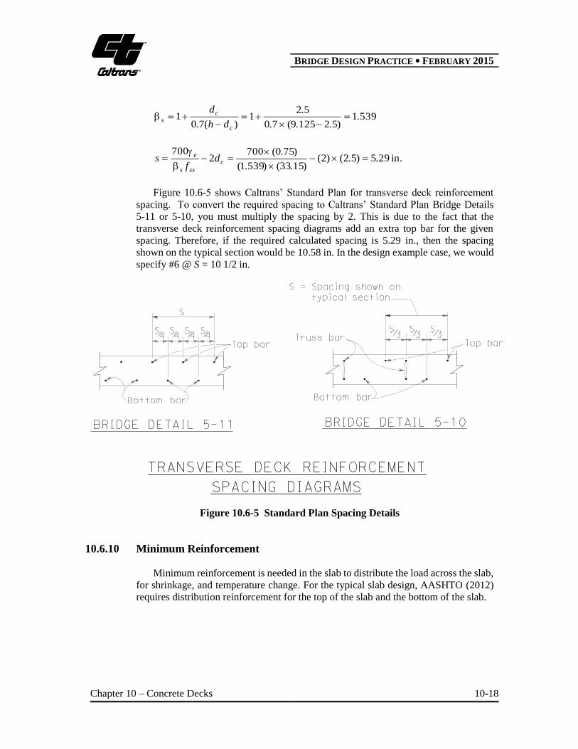
Figure 10.6-5 shows Caltrans’ Standard Plan for transverse deck reinforcement
spacing. To convert the required spacing to Caltrans’ Standard Plan Bridge Details
5-11 or 5-10, you must multiply the spacing by 2. This is due to the fact that the
transverse deck reinforcement spacing diagrams add an extra top bar for the given
spacing. Therefore, if the required calculated spacing is 5.29 in., then the spacing
shown on the typical section would be 10.58 in. In the design example case, we would
specify #6 @ S = 10 1/2 in.
Figure 10.6-5 Standard Plan Spacing Details
10.6.10 Minimum Reinforcement
Minimum reinforcement is needed in the slab to distribute the load across the slab,
for shrinkage, and temperature change. For the typical slab design, AASHTO (2012)
requires distribution reinforcement for the top of the slab and the bottom of the slab.
B BRIDGE DESIGN PRACTICE ● FEBRUARY 2015
Chapter 10 – Concrete Decks 10-19
10.6.10.1 Top of Slab Shrinkage and Temperature Reinforcement
The top slab reinforcement is for shrinkage and temperature changes near the
surface of the exposed concrete slab. The area of reinforcement has to meet the
following requirements:
y
sf)hb(
bh.A
2
31 (AASHTO 5.10.8-1)
600110 .A. s (AASHTO 5.10.8-2)
where:
As = area of reinforcement in each direction and each face (in.2/ft)
b = least width of component section (in.)
h = least thickness of component section (in.)
fy = specified yield strength of reinforcing bars 75 ksi
For the design example slab:
ft
in.056.0)60)(125.912(2
)125.9)(12(3.1
)(2
3.1 2
ys
fhb
bhA
1100560 ..As , therefore, As = 0.11 as a minimum.
Use #4 bars in top slab.
Bar area = 0.2 in.2
Bar spacing = .in8.2111.0
)2.0(12 use maximum 18.0 in.
10.6.10.2 Bottom of Slab Distribution Reinforcement
The reinforcement in the bottom of the slab is a percentage of the primary deck
reinforcement. The primary deck reinforcement is perpendicular to the direction of
traffic, therefore, the requirement is 67220 S percent, where S is the effective span
length (ft) as specified in Article 9.7.2.3. For the design example, the effective span
length is the clear distance from face of girder to face of girder, which is 11 ft.
%%S 676611220220
ft
in.67.001.166.02
requiredA
B BRIDGE DESIGN PRACTICE ● FEBRUARY 2015
Chapter 10 – Concrete Decks 10-20
To facilitate better lateral load distribution, Caltrans’ Reinforced Concrete
Technical Committee recommends that the bottom deck reinforcement be placed
within the center half of the deck span. Therefore,
ft5.52
11
2
1S
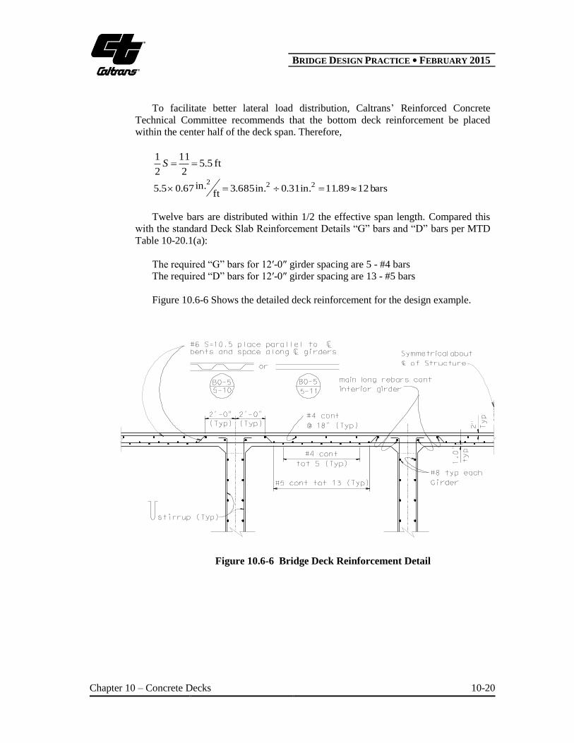
bars1289.11in.31.0in.685.3ft
in.67.05.5 222
Twelve bars are distributed within 1/2 the effective span length. Compared this
with the standard Deck Slab Reinforcement Details “G” bars and “D” bars per MTD
Table 10-20.1(a):
The required “G” bars for 12′-0″ girder spacing are 5 - #4 bars
The required “D” bars for 12′-0″ girder spacing are 13 - #5 bars
Figure 10.6-6 Shows the detailed deck reinforcement for the design example.
Figure 10.6-6 Bridge Deck Reinforcement Detail

B BRIDGE DESIGN PRACTICE ● FEBRUARY 2015
Chapter 10 – Concrete Decks 10-21
NOTATION
As = area of tension reinforcement (in.2)
a = depth of equivalent rectangular stress block (in.)
b = with of the compression fact of the member (in.)
Cbottom = required concrete cover over bottom deck reinforcing steel (in.)
Ctop = required concrete cover over top deck reinforcing steel (in.)
cd = thickness of concrete cover measured from extreme tension fiber to center of bar
(in.)
de = effective depth from extreme compression fiber to the centroid of the tensile
force in the tension reinforcement (in.)
cf = specified compressive strength of concrete for use in design (ksi)
fy = specified minimum yield strength of reinforcing bars (ksi)
fss = tensile stress in mild steel reinforcement at the service limit state (ksi)
h = overall thickness of deck (in.)
Icr = moment of inertia of the cracked section, transformed to concrete (in.4)
IM = dynamic load allowance
MDC = moment due to dead load (kip-ft)
MDW = moment due to dead load wearing surface (kip-ft)
MLL = moment due to live load (kip-ft)
Ms = moment due to service loads (kip-ft)
Mu = factored moment at the section (kip-ft)
m = multiple presence factor
N = number of girders
n = modular ratio = Es/Ec
S = center to center spacing of girder (ft.); effective span length (ft)
t = thickness of slab (in.)
w = uniform load (k/ft)
y = distance from neutral axis location to the extreme tension fiber (in.)
e = crack control exposure condition factor
DC = load factor for permanent dead load
DW = load factor for component dead load

B BRIDGE DESIGN PRACTICE ● FEBRUARY 2015
Chapter 10 – Concrete Decks 10-22
LL = load factor for live load
= load modifier
= resistance factor
B BRIDGE DESIGN PRACTICE ● FEBRUARY 2015
Chapter 10 – Concrete Decks 10-23
REFERENCES
1. AASHTO, (2012). AASHTO LRFD Bridge Design Specifications, Customary U.S. Units
(6th Edition), American Association of State Highway and Transportation Officials, 4th
Edition, Washington, D.C.
2. Caltrans, (2014). California Amendments to AASHTO LRFD Bridge Design Specifications
– 6th Edition, California Department of Transportation, Sacramento, CA.
3. Caltrans, (2008). Bridge Memo to Designers (MTD) 10-20: Deck and Soffit Slabs,
California Department of Transportation, Sacramento, CA.
4. Caltrans, (2010). Bridge Memo to Designers (MTD) 10-20: Protection of Reinforcement
Against Corrosion Due to Chlorides, Acids Sulfates, California Department of
Transportation, Sacramento, CA.
5. Caltrans, (2002). Bridge Memo to Designers (MTD) 10-5: Protection of Reinforcement
Against Corrosion Due to Chlorides, Acids and Sulfates, California Department of
Transportation, Sacramento, CA.
6. Caltrans, (1986). Bridge Design Details (BDD) 8-34: Variable Bay Transverse
Reinforcement, California Department of Transportation, Sacramento, CA.
7. Caltrans, (1971). Bridge Design Details (BDD) 8-36: Skewed Deck Corner Reinforcement,
California Department of Transportation, Sacramento, CA.
8. Caltrans, (2015). Standard Plans, California Department of Transportation, Sacramento,
CA.
9. Chen, W. F., and Duan, L. (2014). Bridge Engineering Handbook, 2nd Edition, CRC Press,
Boca Raton, FL.
10. Csagoly, P. and Lybas, J. (1989). “Advance Design Method for Concrete Bridge Deck
Slabs,” Concrete International, ACI. Vol.11.
11. Fu, G. K., et al, (2000). “Effect of Truck Weight on Bridge Network Costs”, NCHRP:
Report 495, Transportation Research Board, Washington, D.C.

B BRIDGE DESIGN PRACTICE ● FEBRUARY 2015
Chapter 10 – Concrete Decks 10-24
This page is intentionally left blank.