Embed Size (px)
Citation preview

1-1
Chapter 1
Tune-up and routine maintenance
Contents
Sect/on Air filter element - cleaning and replacement................................ 12 Battery - check............................................................................... 4 Brake pads/linings - wear check.................................................... 5 Brake system - checks................................................................... 6 Carburetor synchronization - check and adjustment..................... 18 Clutch - checks and bleeding ........................................................ 9 Cooling system - check ................................................................. 19 Cooling system - draining, flushing and refilling ............................ 20 Crankcase breather - check........................................................... 21 Cylinder compression - check ....................................................... 13 Engine oil/filter - change ................................................................ 10 Evaporative emission control system and Secondary air
supply system (California models only) - check....................... 22 Exhaust system - check................................................................. 23 Fasteners - check........................................................................... 25
Sect/on Final drive unit - oil change............................................................ 11 Fluid levels - check......................................................................... 3 Fuel system - checks and filter replacement................................. 26 Idle speed - check and adjustment................................................ 17 Introduction to tune-up and routine maintenance......................... 2 Lubrication - general...................................................................... 15 Routine maintenance intervals....................................................... 1 Spark plugs - check and replacement........................................... 14 Stands- check............................................................................... 28 Steering head bearings - check and adjustment........................... 24 Suspension - check........................................................................ 27 Tires/wheels - general check ......................................................... 7 Throttle and choke operation/grip freeplay - check
and adjustment......................................................................... 8 Valve clearances - check and adjustment..................................... 16
Specifications
Engine Spark plug type
Standard............................................................................................. NGK DPR8EA-9 or ND X24EPR-U9 Below 41°F (5°C)................................................................................ NGK DPR7EA-9 or ND X22EPR-U9 Extended high speeds........................................................................ NGK DPR9EA-9 or ND X27EPR-U9
Spark plug electrode gap ........................................................................ 0.8 to 0.9 mm (0.031 to 0.035 in) Valve clearances (COLD engine)
1982 through 1984 700/750 Magnas and all 700/750 Sabre models.................................................................. 0.12 mm (0.0047 in)
1985 700 Magna models.................................................................... 0.13 mm (0.0051 in) 1986-on 700/750 and all 1100 models .............................................. 0.15 mm (0.0059 in)
Engine idle speed 750 Sabre and 1982 through 1984 700/750 Magna models ............. 1000 ± 100 rpm 700 Sabre and 1985-on 700/750 Magna models .............................. 1200 ± 100 rpm 1100 Sabre models............................................................................ 1000 to 1100 rpm 1100 Magna models........................................................................... 1000 ± 100 rpm
Cylinder compression pressures............................................................. 184 ±28 psi (psi) Carburetor synchronization (maximum vacuum difference between any two cylinders
1985 through 1988 700/750 Magna models...................................... 40 mm (1.6 in) Hg All other models ................................................................................. 60 mm (2.4 in) Hg
Cylinder identification.............................................................................. See illustration 1.1 in Chapter 2 Miscellaneous Battery electrolyte specific gravity........................................................... 1.280 at 68°F (20°C) Brake pad minimum thickness ................................................................ See text Brake pedal freeplay (700/750 models)................................................... 20 to 30 mm (0.8 to 1.2 in) Throttle grip freeplay................................................................................ 2 to 6 mm (0.08 to 0.24 in)

Chapter 1 Tune-up and routine maintenance
1-2
Tire sizes Front Rear 700/750 Sabre models....................................................................... 110/90-18 61H 130/90-17 68H 1982 through 1984 700/750 Magna models...................................... 110/90-18 61H 130/90-16 67H 1985 and 1986 700 Magna models.................................................... 110/90-18 61H 140/90-15 70H 1987 and 1988 700/750 Magna models ............................................ 100/90-19 57H 150/80-15 70H 1100 Sabre models............................................................................ M110/90-18 M130/90-17 1100 Magna models........................................................................... M110/90-18 M140/90-16
Minimum tire tread depth*....................................................................... 1.5 mm (0.06 in) 2.0 mm (0.08 in) Tire pressures (cold)
1100 Sabres Up to 90 kg (200 Ib) load .............................................................. 32 psi 36 psi Over 90 kg (200 Ib) load................................................................ 32 psi 40 psi
700/750 Sabres, 1982 through 1984 700/750 Magnas, all 1100 Magnas Up to 90 kg (200 Ib) load .............................................................. 32 psi 32 psi Over 90 kg (200 Ib) load................................................................ 32 psi 40 psi
1985 through 1988 700/750 Magnas Up to 90 kg (200 Ib) load .............................................................. 32 psi 32 psi Over 90 kg (200 Ib) load................................................................ 32 psi 42 psi
'In the UK, tread depth must be at least 1 mm over 3/4 of the tread breadth all the way around the tire, with no bald patches.
Torque setting Nm ft-ibs Engine oil pan drain plug......................................................................... 35 to 40 25 to 29 Front cylinder oil drain plug..................................................................... 10 to 14 7 to 10 Oil filter (using Honda tool)...................................................................... 15to20 11 to 14 Spark plugs.............................................................................................. 12 to 16 9 to 12
Recommended lubricants and fluids Engine/transmission oil
Type.................................................................................................... API grade SE or SF Viscosity............................................................................................. SAE10W/40 Capacity (700/750 models)
After draining ................................................................................ 2.9 lit (3.1 US qt, 5.1 Imp pts) After engine rebuild....................................................................... 3.0 lit (3.2 US qt, 5.3 Imp pts)
Capacity (1100 models) After draining ................................................................................ 3.0 lit (3.2 US qt, 5.3 Imp pts) After engine rebuild....................................................................... 3.5 lit (3.7 US qt, 6.2 Imp pts)
Final drive unit Type
1982 and 1983 750 models (above 41°F/5°C).............................. Hypoid gear oil SAE90 1982 and 1983 750 models (below 41°F/5°C).............................. Hypoid gear oil SAE80 All other models............................................................................ Hypoid gear oil SAE80
Capacity* 1982 and 1983 750 models.......................................................... 110 cc (3.7 US fl oz, 3.9 Imp fl oz) 1984-on 700/750 models and all 1100 models............................ 130 cc (4.4 Usfl oz, 4.6 Imp fl oz)
"Refill quantity is greater if the final drive has been dismantled Coolant
Mixture type ....................................................................................... 50% distilled water, 50% corrosion inhibited ethylene glycol antifreeze Radiator capacity
700/750 models............................................................................ 2.4 lit (2.5 US qt, 4.2 Imp pt) 1100 Sabre model......................................................................... 2.8 lit (2.9 US qt, 4.9 Imp pt) 1100 Magna model....................................................................... 3.0 lit (3.2 US qt, 5.3 Imp pt)
Reservoir tank capacity (approx.) 1100 Sabre model......................................................................... 0.6 lit (0.6 US qt, 1.0 Imp pt) All other models............................................................................ 0.4 lit (0.4 US qt, 0.7 Imp pt)
Brake and clutch fluid.............................................................................. DOT 3 or 4 (see reservoir cap)
Miscellaneous Wheel bearings........................................................................................ Medium weight, lithium-based multi-purpose grease Final drive flange grease.......................................................................... See Chapter 6 Swingarm pivot bearings......................................................................... Molybdenum disulfide grease Suspension linkage bearings (Sabre)...................................................... Molybdenum disulfide grease Cables and lever pivots........................................................................... Chain and cable lubricant or 10W40 motor oil Stand pivots............................................................................................. Medium-weight, lithium-based multi-purpose grease Brake pedal/shift lever pivots.................................................................. Chain and cable lubricant or 10W40 motor oil Throttle grip............................................................................................. Multi-purpose grease or dry film lubricant

Chapter 1 Tune-up and routine maintenance 1-3
Honda 700, 750 & 1100 V-Four Routine maintenance intervals
Routine maintenance intervals
1
Note: The pre-ride inspection outlined in the owner's manual covers the checks and maintenance that should be carried out on a daily basis. It's condensed and included here to remind you of its importance. Always perform the pre-ride inspection at every maintenance interval (in addition to the procedures listed). The intervals listed below are the shortest intervals recommended by the manufacturer for each particular operation during the model years covered in this manual. Your owner's manual may have different intervals for your model.
Daily or before riding
Check the engine oil level Check the fuel level and inspect for leaks Check the engine coolant level and look for leaks Check the operation of both brakes - also check the fluid
levels and look for leakage Check the tires for damage, the presence of foreign objects
and correct air pressure Check the throttle for smooth operation Check the operation of the clutch - make sure the freeplay
is correct Make sure the steering operates smoothly, without
looseness or binding Check for proper operation of the headlight, taillight,
brake light, turn signals, indicator lights, speedometer and horn Make sure the sidestand and main stand
return to their fully up positions and stay there under spring pressure
Make sure the engine stop switch works properly
After the initial 600 miles (1000 km)
Replace the engine oil and oil filter Check and adjust the valve clearances Check and adjust the idle speed Check the throttle operation Check the carburetor synchronization Check the cooling system Check the brake hydraulic system Check the clutch hydraulic system Check the tightness of all fasteners Check the steering head bearings
Every 4000 miles (6000 km)
Clean the air filter element(s) (Sabre models) Drain the crankcase breather separator tank (where applicable)
Replace the spark plugs Check the idle speed Check the battery electrolyte level and condition Check the brake fluid level and pad wear Check the drum brake lining wear Check the clutch fluid level
Every 8000 miles (12,000 km)_________
Replace the engine oil and filter Check the fuel system hoses Check the battery Check and adjust the throttle and choke cables Check/adjust the valve clearances Replace the air cleaner element (1982 through 1985
Magna models) Check/adjust the carburetor synchronization Check the Evaporative emission control system (1982
through 1985 models) Check the Secondary air supply system (1986 through
1988 models) Check the coolant level and check the cooling system Check the final drive oil level Lubricate the final driven flange with fresh grease - 700/750
Sabres and 1982 through 1984 700/750 Magnas (see Chapter 6)
Check the brake hydraulic system Check the operation of the brake light switches Check the headlight aim (see Chapter 8) Check the clutch hydraulic system Check the stand pivots Check the operation of the suspension Check the steering head bearings for play Check the condition of the wheels and tires Check the tightness of all nuts, bolts and fasteners
Every 12,000 miles (19,200 km)________
Replace the air filter element (1986 through 1988 Magnas) Check the Evaporative emission control system (1986
through 1988 models) Replace the clutch and brake fluid (or every two years,
whichever comes sooner)
Every 24,000 miles (36,000 km)________
Replace the coolant Replace the fuel filter (1982 through 1986 Magnas and
1100 Sabres) Replace the final drive oil

Chapter 1 Tune-up and routine maintenance
1-4
3.2 Rotate the wiper to clear the oil level inspection window (1982 750 models)
3.3 Add engine oil via the plug in the front of the right engine case
2 Introduction to tune-up and routine maintenance
This Chapter covers in detail the checks and procedures necessary for the tune-up and routine maintenance of your motorcycle. Section 1 includes the routine maintenance schedule, which is designed to keep the machine in proper running condition and prevent possible problems. The remaining Sections contain detailed procedures for carrying out the items listed on the maintenance schedule, as well as additional maintenance information designed to increase reliability.
Since routine maintenance plays such an important role in the safe and efficient operation of your motorcycle, it is presented here as a comprehensive check list. For the rider who does all his/her own maintenance, these lists outline the procedures and checks that should be done on a routine basis.
Maintenance information is printed on decals attached to the motorcycle. If the information on the decals differs from that included here, use the information on the decal.
Deciding where to start or plug into the routine maintenance schedule depends on several factors. If you have a motorcycle whose warranty has recently expired, and if it has been maintained according to the warranty standards, you may want to pick up routine maintenance as it coincides with the next mileage or calendar interval. If you have owned the machine for some time but have never performed any maintenance on it, then you may want to start at the nearest interval and include some additional procedures to ensure that nothing important is overlooked. If you have just had a major engine overhaul, then you may want to start the maintenance routine from the beginning. If you have a used machine and have no knowledge of its history or maintenance record, you may desire to combine all the checks into one large service initially and then settle into the maintenance schedule prescribed.
The Sections which outline the inspection and maintenance procedures are written as step-by-step comprehensive guides to the performance of the work. They explain in detail each of the routine inspections and maintenance procedures on the check list. References to additional information in applicable Chapters is also included and should not be overlooked.
Before beginning any maintenance or repair, the machine should be cleaned thoroughly, especially around the oil filter, spark plugs, cylinder head covers, side covers, carburetors, etc. Cleaning will help ensure that dirt does not contaminate the engine and will allow you to detect wear and damage that could otherwise easily go unnoticed.
3 Fluid levels - check
Engine oil Refer to illustrations 3.2, 3.3 and 3.7
1982 750 models 1 Check the oil level with the engine cold. Place the motorcycle on its main stand on level ground. 2 Locate the engine oil inspection window on the lower right side of the engine. If necessary, use a screwdriver to rotate the wiper in order to clean the inspection window (see illustration). 3 Note where the oil level is in relation to the upper and lower level marks located on either side of the inspection window. The level should be between these two marks. If the oil level is below the lower mark, remove the filler cap and add enough oil of the recommended grade and type to bring the level up to the upper mark (see illustration). Do not overfill. Re-install the filler cap. 4 Run the engine and check that the oil pressure warning light goes out after a few seconds.
All other models 5 Run the engine for 2 to 3 minutes, then stop it. Caution: Do not run the engine in an enclosed space such as a garage or shop. Place the motorcycle on its main stand (have an assistant hold it vertical on 1987 and 1988 700/750 Magna models) on level ground. 6 Remove the oil level dipstick from the rear of the engine right cover and wipe its end clean. Re-insert the dipstick, but don't screw it in, then remove it and check the oil level. 7 Note where the oil level is in relation to the upper and lower level marks on the dipstick. The level should be between these two marks. If the oil level is below the lower mark, remove the filler cap and add enough oil of the recommended grade and type to bring the level up to the upper mark (see illustration). Do not overfill. Re-install the filler cap. 8 Some later 700/750 models retain the oil level inspection window (see Step 2), although the dipstick method is recommended. 9 Run the engine and check that the oil pressure warning light goes out after a few seconds.
Brake fluid Refer to illustration 3.12 10 In order to ensure proper operation of the hydraulic disc brakes,

Chapter 1 Tune-up and routine maintenance 1-5
3.7 Oil level should lie between dipstick marks (all except 1882 750 models)
3.12 Brake/clutch fluid level must be above LOWER mark on master cylinder
the fluid level in the master cylinder reservoir(s) must be properly maintained.
Front brake 11 With the motorcycle on the main stand (or held upright), turn the handlebars until the top of the master cylinder is as level as possible. If necessary, tilt the motorcycle to make it level. 12 Look closely at the inspection window in the master cylinder reservoir. Make sure that the fluid level, visible in the sightglass, is above the LOWER mark on the reservoir (see illustration). 13 If the level is low, the fluid must be replenished. Before removing the master cylinder cover, cover the fuel tank to protect it from brake fluid spills (which will damage the paint) and remove all dust and dirt from the area around the cap. 14 Unscrew the retaining screws and lift off the cover, diaphragm plate (where fitted), diaphragm and float (1988 750 Magna model). Using a good quality brake fluid of the recommended type, from a freshly opened container, top up the reservoir to the upper level mark; this mark is in the form of a line, cast on the inside of the front face of the reservoir. 15 When the fluid level is correct, clean and dry the diaphragm, fold it into its compressed state and install it in the reservoir followed by the diaphragm plate. Install the reservoir cover and securely tighten its retaining screws.
Rear brake (1100 models) 16 With the motorcycle on the main stand, remove the right side cover and check the fluid level in the rear brake reservoir. Make sure that the fluid level, visible through the translucent material of the reservoir, is above the LOWER mark on the reservoir. 17 If the level is low, the fluid must be replenished. Remove any dust and dirt from the area around the cap. Unscrew the reservoir cap and remove the diaphragm plate and diaphragm. Using a good quality brake fluid of the recommended type, from a freshly opened container, top up the reservoir to the UPPER level mark. 18 When the fluid level is correct, clean and dry the diaphragm, fold it into its compressed state and install it in the reservoir followed by the diaphragm plate. Install the reservoir cap, tightening it securely, and install the right side cover.
Both brakes 19 Check the operation of both brakes before riding the motorcycle; if there is evidence of air in the system, it must be bled as described in Chapter 7. 20 If the brake fluid level was low, inspect the brake system for leaks.
Clutch fluid 21 The procedure for checking the clutch fluid is identical to the front brake fluid checking procedure above.
Coolant level Refer to illustration 3.23 22 Remove the left side cover on 700/750 Sabres, or the right side cover on all other models. 23 Start the engine and allow it to idle until it reaches normal operating temperature. With the engine thoroughly warmed up, the coolant level in the reservoir should be between the Upper and Lower marks on the side of the reservoir (see illustration). 24 If the coolant is below the Lower mark, remove the cap from the reservoir tank and add coolant of the specified type (see Specifi-cations) to bring the level to the Upper mark. Note: Be careful not to spill coolant on any painted surfaces, as damage to the paint could occur. 25 Re-install the reservoir cap and the side cover. 26 If the coolant is significantly above the upper level mark at any time, the surplus coolant should be siphoned off to prevent it from being expelled out of the breather hose when the engine is running. 27 If the coolant level falls steadily, check the system for leaks as
3.23 Coolant level should lie between UPPER and LOWER lines on reservoir tank

Chapter 1 Tune-up and routine maintenance
1-6
3.29 Final drive unit oil filler cap (A) and drain bolt (B) 4.1 Battery electrolyte level should lie between level marks on casing
described in Section 19. If no leaks are found and the level still continues to fall, it is recommended that the machine be taken to a Honda service agent who will pressure test the system.
Final drive unit oil Refer to illustration 3.29 28 If the motorcycle has just been ridden, wait ten minutes for the oil to settle before checking the level. Place the motorcycle on its main stand. Be sure it is on level ground. 29 On 1982 and 1983 750 models, remove the oil filler cap (see illustration). Look into the aperture, using a hand-held flashlight if necessary, and locate the step in the casting. Align the top edge of one of the ring gear teeth with the top of the step (rotate the rear wheel to move the ring gear) - at this point the oil should be level with the top of the next tooth down on the ring gear. If the oil level is lower than this, add more oil of the correct type and grade, using a funnel, syringe or pump, to bring it to its proper level. 30 On all other models, remove the oil filler cap (see illustration 3.29). The level of the oil should be just at the lower edge of the oil filler hole. If the oil level is lower than this, add more oil of the correct type and grade, using a funnel, syringe or pump, to bring it to its proper level. 31 On all models, re-install the oil filler cap, tightening it securely.
4 Battery - check
Battery electrolyte Caution: Take care when working with the battery that you do not allow the electrolyte to contact your eyes, skin or clothing, as it contains sulphuric acid. Flush any contacted area immediately with plenty of water. Any contact with eyes requires prompt medical attention. Refer to illustration 4.1 1 To check the level of the electrolyte in the battery, remove the right side cover (1982 through 1984 700/750 Magnas, all 700/750 Sabres and all 1100 Magnas) or left side cover (1100 Sabres). On 1985 through 1988 700/750 Magnas, the battery must be lifted out of its holder to check the level (see Chapter 8). The level should be between the Upper and Lower level marks printed on the outside of the battery case (see illustration). 2 If the electrolyte level is at or below the Lower mark, the battery must be removed in order to add more water (see Chapter 8). 3 With the battery removed from the motorcycle, remove each cell cap and add enough distilled water to each cell to bring the level to the
4.6 Measuring electrolyte specific gravity with a hydrometer
Upper mark. Do not overfill. Also, do not use tap water, except in an emergency, as this will shorten the service life of the battery. The cell holes are quite small so it may help to use a plastic squeeze bottle with a small spout to add the water. 4 After filling install the battery and ensure its vent hose is routed correctly (see Chapter 8).
Specific gravity check Refer to illustration 4.6 5 Remove the battery (see Chapter 8). Check the specific gravity of the electrolyte in each cell using a small hydrometer made especially for motorcycle batteries. These are available from most dealer parts departments. 6 Remove the caps, draw some electrolyte from the first cell into the hydrometer and note the specific gravity (see illustration). Compare the reading to the Specifications listed in this Chapter. Note: Add 0.004 points to the reading for every 10°F above 68°F (20°C) -subtract 0.004 points from the reading for every 10°F below 68°F (20°F). Return the electrolyte to the cell and repeat the check for the remaining cells. When the check is complete, rinse the hydrometer thoroughly with clean water. 7 If the specific gravity of the electrolyte in each cell is as specified, the battery is in good condition and is apparently being charged by the motorcycle's charging system.

Chapter 1 Tune-up and routine maintenance 1-7
5.1 Brake pad wear can be checked through inspection window in caliper body (arrow)
5.2 Brake pad wear cutout (upper arrow) and wear grooves (lower arrow)
5.4 Drum brake linings are worn when indicator pointer and index
mark align
8 If the specific gravity is low, the battery is not fully charged. This may be due to corroded battery terminals, a dirty battery case, a malfunctioning charging system, or loose or corroded wiring connections. On the other hand, it may be that the battery is worn out, especially if the motorcycle is old, or that infrequent use of the motorcycle prevents normal charging from taking place. 9 Be sure to correct any problems and charge the battery if necessary. Refer to Chapter 8 for additional battery maintenance and charging procedures. 10 Install the battery (see Chapter 8).
5 Brake pads/linings - wear check
Disc brake pads Refer to illustrations 5.1 and 5.2 1 A quick check of the brake pads can be made without removing them from the caliper. Pad wear can be judged by viewing the pad material through the inspection slot indicated by the cast arrow on the caliper body; the use of a hand-held flashlight will aid visibility. The original equipment pads have a cutout between the pad metal backing and the friction material which denotes the wear limit - if the friction material of either pad has worn down to expose the cutout, the pads
must be replaced (see illustration). 2 As a further check, view the pads from the caliper mouth. If the friction material has worn down level with the base of the grooves or slots in the pad, the need for replacement is indicated (see illustration). Refer to Chapter 7 for the pad replacement procedure. However, it is recommended that the pads be removed and a more detailed inspection be carried out as described in Sections 2 and 15 of Chapter 7. 3 If it is impossible to check the amount of pad material remaining due to a build-up of road dirt, remove the pads for thorough inspection and cleaning (see Chapter 7).
Drum brake linings (700/750 models) Refer to illustration 5.4 4 The drum brake shoes are checked by applying the brake fully and checking to see whether the wear indicator pointer on the brake lever aligns with the index mark on the brake panel (see illustration). 5 If it aligns with the index mark or exceeds it, the brake shoes are worn and must be replaced with new ones (see Chapter 7). If in any doubt about the amount of lining material remaining on the shoes, or if brake action is poor, remove the wheel for measurement of the lining thickness (see Chapter 7).
6 Brake system -
checks Brake checks 1 A routine general check of the brakes will ensure that any problems are discovered and remedied before the rider's safety is jeopardized. 2 Check the brake lever and pedal for loose connections, excessive play, bends, and other damage. Replace any damaged parts with new ones (see Chapter 7). 3 Make sure all brake fasteners are tight. Check the brake pads/linings for wear (see Section 5) and on disc brake models, make sure the fluid level in the reservoirs is correct (see Section 3). 4 On disc brakes, look for leaks at the hose connections and check for cracks in the hoses. If the lever or pedal is spongy, bleed the brakes as described in Chapter 7. Drain and replace the brake fluid at the specified interval.
Brake lever freeplay (1985 1100 Sabre and 1985/86 1100 Magna) 5 Measure the freeplay at the ball end of the front brake lever. Assuming that there is no air in the hydraulic system, resulting in a
Chapter 1 Tune-up and routine maintenance 1-8
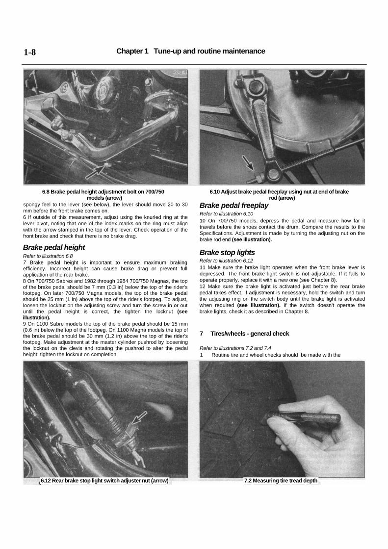
6.8 Brake pedal height adjustment bolt on 700/750 models (arrow)
6.10 Adjust brake pedal freeplay using nut at end of brake rod (arrow)
spongy feel to the lever (see below), the lever should move 20 to 30 mm before the front brake comes on. 6 If outside of this measurement, adjust using the knurled ring at the lever pivot, noting that one of the index marks on the ring must align with the arrow stamped in the top of the lever. Check operation of the front brake and check that there is no brake drag.
Brake pedal height Refer to illustration 6.8 7 Brake pedal height is important to ensure maximum braking efficiency. Incorrect height can cause brake drag or prevent full application of the rear brake. 8 On 700/750 Sabres and 1982 through 1984 700/750 Magnas, the top of the brake pedal should be 7 mm (0.3 in) below the top of the rider's footpeg. On later 700/750 Magna models, the top of the brake pedal should be 25 mm (1 in) above the top of the rider's footpeg. To adjust, loosen the locknut on the adjusting screw and turn the screw in or out until the pedal height is correct, the tighten the locknut (see illustration). 9 On 1100 Sabre models the top of the brake pedal should be 15 mm (0.6 in) below the top of the footpeg. On 1100 Magna models the top of the brake pedal should be 30 mm (1.2 in) above the top of the rider's footpeg. Make adjustment at the master cylinder pushrod by loosening the locknut on the clevis and rotating the pushrod to alter the pedal height; tighten the locknut on completion.
Brake pedal freeplay Refer to illustration 6.10 10 On 700/750 models, depress the pedal and measure how far it travels before the shoes contact the drum. Compare the results to the Specifications. Adjustment is made by turning the adjusting nut on the brake rod end (see illustration).
Brake stop lights Refer to illustration 6.12 11 Make sure the brake light operates when the front brake lever is depressed. The front brake light switch is not adjustable. If it fails to operate properly, replace it with a new one (see Chapter 8). 12 Make sure the brake light is activated just before the rear brake pedal takes effect. If adjustment is necessary, hold the switch and turn the adjusting ring on the switch body until the brake light is activated when required (see illustration). If the switch doesn't operate the brake lights, check it as described in Chapter 8.
7 Tires/wheels - general check
Refer to illustrations 7.2 and 7.4 1 Routine tire and wheel checks should be made with the
6.12 Rear brake stop light switch adjuster nut (arrow) 7.2 Measuring tire tread depth

Chapter 1 Tune-up and routine maintenance
7.4 Measuring tire air pressure
realization that your safety depends to a great extent on their condition. 2 Check the tires carefully for cuts, tears, embedded nails or other sharp objects and excessive wear. Operation of the motorcycle with excessively worn tires is extremely hazardous, as traction and handling are directly affected. Measure the tread depth at the center of the tire and replace worn tires with new ones when the tread depth is less than specified (see illustration). 3 Repair or replace punctured tires as soon as damage is noted. Do not try to patch a torn tire, as wheel balance and tire reliability may be impaired. 4 Check the tire pressures when the tires are cold and keep them properly inflated (see illustration). Proper air pressure will increase tire life and provide maximum stability and ride comfort. Keep in mind that low tire pressures may cause the tire to slip on the rim or come off, while high tire pressures will cause abnormal tread wear and unsafe handling. 5 The cast wheels used on this machine are virtually maintenance free, but they should be kept clean and checked periodically for cracks and other damage. Never attempt to repair damaged cast wheels; they must be replaced with new ones. 6 Check the valve rubber for signs of damage or deterioration and have it replaced if necessary. Also, make sure the valve stem cap is in place and tight. If it is missing, install a new one made of metal or hard plastic.
8.3a With the throttle at rest, mark the relationship of the grip to the right switch assembly ...
8 Throttle and choke operation/grip freeplay - check and adjustment
Throttle cables Refer to illustrations 8.3a, 8,3b, 8.4 and 8.5 1 Make sure the throttle grip rotates easily from fully closed to fully open with the front wheel turned at various angles. The grip should return automatically from fully open to fully closed when released. 2 If the throttle sticks, this is probably due to a cable fault. Remove the cables as described in Chapter 4 and lubricate them as described in Section 15. Install each cable, routing them so they take the smoothest route possible. If this fails to improve the operation of the throttle, the cables must be replaced. Note that in very rare cases the fault could lie in the carburetors rather than the cables, necessitating the removal of the carburetors and inspection of the throttle linkage (see Chapter 4). 3 With the throttle operating smoothly, check for a small amount of freeplay at the grip. The amount of freeplay in the throttle cables, measured in terms of twistgrip rotation, should be as given in this Chapter's Specifications (see illustrations). If adjustment is necessary, adjust idle speed first (see Section 17). 4 Loosen the locknut on the cable upper adjuster and rotate the adjuster until the correct amount of freeplay is obtained, then tighten
1-9
8.3b ... then measure the distance the throttle grip can be rotated before a slight resistance is felt
8.4 Throttle cable upper adjuster (arrow).

Chapter 1 Tune-up and routine maintenance 1-10
8.5 ... and lower adjuster on carburetors (arrow) 9.4 When bleeding the clutch connect tube to bleed valve as shown
the locknut (see illustration). If it is not possible to obtain the correct freeplay with the upper adjuster, it will also be necessary to make adjustment at the lower adjuster, situated on the carburetors. 5 To gain access to the lower adjuster remove the fuel tank or trig it up on early Magnas (see Chapter 4) (see illustration). Screw the upper cable adjuster in to obtain the maximum possible freeplay, then loosen the lower adjuster locknut and set the cable freeplay using first the lower adjuster and then, if necessary, the upper adjuster. Once the freeplay is correct tighten the locknuts securely. 6 Check that the throttle twistgrip operates smoothly and snaps shut quickly when released. Warning: Turn the handlebars all the way through their travel with the engine idling. Idle speed should not change. If it does, the cables may be routed incorrectly. Correct this condition before riding the bike (see Chapter 4). Choke cable 7 Proper choke operation will ensure fast starts and quick engine warm up. Initially, move the choke lever up and down making sure it moves smoothly. 8 If there is any binding or drag in the lever's operation, the cable should be checked for kinks or damage to the cable casing and then removed (see Chapter 4) and lubricated as described in Section 15. 9 If cable lubrication fails to improve the operation of the choke, the cable must be replaced. Note that in very rare cases the fault could lie in the carburetors rather than the cable, necessitating the removal of the carburetors and inspection of the choke plungers as described in Chapter 4. 10 With the choke mechanism operating smoothly, check the choke cable freeplay as described in Chapter 4. 11 Once the choke mechanism is correctly adjusted, install the air filter housing and fuel tank as described in Chapter 4.
9 Clutch - checks and bleeding
Refer to illustration 9.4 1 Check the clutch lever for loose connections, excessive play, bends, and other damage. Replace any damaged parts with new ones (see Chapter 2). 2 On 1985 1100 Sabres and 1985/86 1100 Magna models, measure the freeplay at the ball end of the clutch lever. Assuming that there is no air in the hydraulic system, resulting in a spongy feel to the lever (see below), the lever should move 20 to 30 mm before the clutch disengages. If outside of this measurement, adjust using the knurled ring at the lever pivot, noting that the index mark on the ring must align with the arrow stamped in the top of the lever. Start the engine and check that the clutch disengages and engages smoothly, without slip or drag.
3 Check that the fluid level in the reservoir is correct (see Section 3). Look for leaks at the hose connections and check for cracks in the hoses. 4 If the lever is spongy, bleed the clutch line of air. The bleeding operation is exactly the same as described for bleeding the brakes in Chapter 7, Section 11. Remove the slave cylinder bleed valve cap, and connect the bleed tube to the valve (see illustration).
10 Engine oil/filter - change
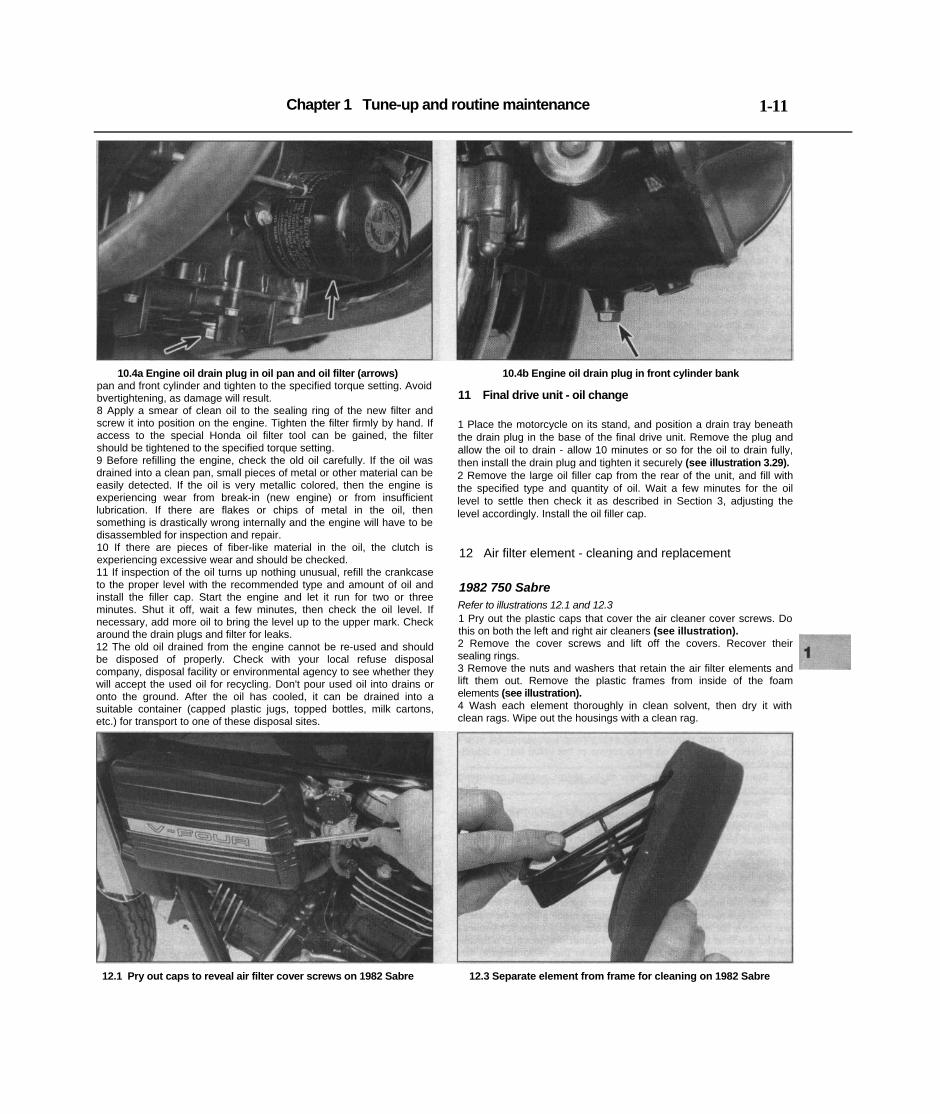
Refer to illustrations 10.4a and 10.4b 1 Consistent routine oil and filter changes are the single most important maintenance procedure you can perform on a motorcycle. The oil not only lubricates the internal parts of the engine, transmission and clutch, but it also acts as a coolant, a cleaner, a sealant, and a protectant. Because of these demands, the oil takes a terrific amount of abuse and should be replaced often with new oil of the recommended grade and type. Saving a little money on the difference in cost between a good oil and a cheap oil won't pay off if the engine is damaged. 2 Before changing the oil and filter, warm up the engine so the oil will drain easily. Be careful when draining the oil, as the exhaust pipes, the engine, and the oil itself can cause severe burns. 3 Put the motorcycle on the main stand (where fitted) and position a clean drain pan below the engine. Unscrew the oil filler cap to vent the crankcase and act as a reminder that there is no oil in the engine. 4 Next, remove the drain plug from the oil pan, as well as the drain plug from the front cylinder head and allow the oil to drain into the pan (on 1987 and 1988 700/750 Magnas hold the motorcycle upright to ensure that the oil drains fully) (see illustrations). Discard the sealing washers on the drain plugs; they should be replaced whenever the plugs are removed. 5 On certain California models, the emission control system canister will prevent access to the oil filter. Disconnect its hoses and remove it from the frame (see Chapter 4). On 1987 and 1988 700/750 Magna models access to the filter is improved is the belly fairing is removed (see Chapter 6). Make sure the drain pan is under the filter, then loosen the oil filter using a strap wrench or the Honda service tool. Warning: Take great care not to burn your hands on the exhaust system. Unscrew the filter from the engine unit and empty its contents into the drain pan. If additional maintenance is planned for this time period, check or service another component while the oil is allowed to drain completely. 6 Clean the filter thread and housing on the crankcase with solvent or clean shop towels. Wipe any remaining oil off the filter sealing area of the crankcase. 7 Slip a new sealing washer over the drain plugs. Fit them to the oil
Chapter 1 Tune-up and routine maintenance 1-11
10.4a Engine oil drain plug in oil pan and oil filter (arrows) 10.4b Engine oil drain plug in front cylinder bank pan and front cylinder and tighten to the specified torque setting. Avoid bvertightening, as damage will result. 8 Apply a smear of clean oil to the sealing ring of the new filter and screw it into position on the engine. Tighten the filter firmly by hand. If access to the special Honda oil filter tool can be gained, the filter should be tightened to the specified torque setting. 9 Before refilling the engine, check the old oil carefully. If the oil was drained into a clean pan, small pieces of metal or other material can be easily detected. If the oil is very metallic colored, then the engine is experiencing wear from break-in (new engine) or from insufficient lubrication. If there are flakes or chips of metal in the oil, then something is drastically wrong internally and the engine will have to be disassembled for inspection and repair. 10 If there are pieces of fiber-like material in the oil, the clutch is experiencing excessive wear and should be checked. 11 If inspection of the oil turns up nothing unusual, refill the crankcase to the proper level with the recommended type and amount of oil and install the filler cap. Start the engine and let it run for two or three minutes. Shut it off, wait a few minutes, then check the oil level. If necessary, add more oil to bring the level up to the upper mark. Check around the drain plugs and filter for leaks. 12 The old oil drained from the engine cannot be re-used and should be disposed of properly. Check with your local refuse disposal company, disposal facility or environmental agency to see whether they will accept the used oil for recycling. Don't pour used oil into drains or onto the ground. After the oil has cooled, it can be drained into a suitable container (capped plastic jugs, topped bottles, milk cartons, etc.) for transport to one of these disposal sites.
11 Final drive unit - oil change
1 Place the motorcycle on its stand, and position a drain tray beneath the drain plug in the base of the final drive unit. Remove the plug and allow the oil to drain - allow 10 minutes or so for the oil to drain fully, then install the drain plug and tighten it securely (see illustration 3.29). 2 Remove the large oil filler cap from the rear of the unit, and fill with the specified type and quantity of oil. Wait a few minutes for the oil level to settle then check it as described in Section 3, adjusting the level accordingly. Install the oil filler cap.
12 Air filter element - cleaning and replacement
1982 750 Sabre Refer to illustrations 12.1 and 12.3 1 Pry out the plastic caps that cover the air cleaner cover screws. Do this on both the left and right air cleaners (see illustration). 2 Remove the cover screws and lift off the covers. Recover their sealing rings. 3 Remove the nuts and washers that retain the air filter elements and lift them out. Remove the plastic frames from inside of the foam elements (see illustration). 4 Wash each element thoroughly in clean solvent, then dry it with clean rags. Wipe out the housings with a clean rag.
12.1 Pry out caps to reveal air filter cover screws on 1982 Sabre 12.3 Separate element from frame for cleaning on 1982 Sabre
Chapter 1 Tune-up and routine maintenance 1-12
5 Soak the clean elements in SAE 80-90 gear oil, then squeeze out as much of the oil as possible (do not wring the element). Hang the elements up and allow any excess oil to drip out - they must not be saturated with oil. 6 Install the filters by reversing the removal steps. Ensure the cover sealing rings are in place and apply a light smear of grease to them.
1983-on 700/750 and all 1100 Sabre models 7 Remove the fuel tank (see Chapter 4). 8 Remove the two air filter cover screws, lift off the cover with its sealing ring and lift out the element together with its support frames. Separate the support frames from the element. 9 Wash the element thoroughly in clean solvent, then dry it with clean rags. Wipe out the housing with a clean rag. 10 Soak the clean element in SAE 80-90 gear oil, then squeeze out as much of the oil as possible (do not wring the element). Hang the element up and allow any excess oil to drip out - it must not be saturated with oil. 11 Install the filter by reversing the removal steps. Ensure the cover sealing ring is in place and apply a light smear of grease to it.
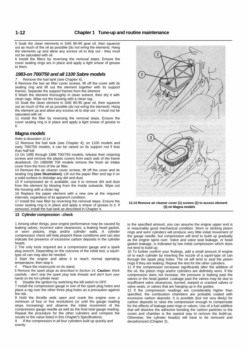
Magna models Refer to illustration 12.14 12 Remove the fuel tank (see Chapter 4); on 1100 models and early 700/750 models, it can be raised on its support rod if less than half full. 13 On 1985 through 1988 700/750 models, release their retaining screws and remove the plastic covers from each side of the frame deadstock. On 1985/86 700 models remove the fresh air intake cover from the front of the air filter. 14 Remove the air cleaner cover screws, lift off the cover and its sealing ring (see illustration). Lift out the paper filter and tap it on a solid surface to dislodge any dirt and dust. 15 If compressed air is available, use it to remove dirt and dust from the element by blowing from the inside outwards. Wipe out the housing with a clean rag. 16 Replace the paper element with a new one at the required intervals, regardless of its apparent condition. 17 Install the new filter by reversing the removal steps. Ensure the cover sealing ring is in place and apply a smear of grease to it. If removed, install the fuel tank as described in Chapter 4.
12.14 Remove air cleaner cover (1) screws (2) to access element (3) on Magna models
13 Cylinder compression - check
1 Among other things, poor engine performance may be caused by leaking valves, incorrect valve clearances, a leaking head gasket, or worn pistons, rings and/or cylinder walls. A cylinder compression check will help pinpoint these conditions and can also indicate the presence of excessive carbon deposits in the cylinder heads. 2 The only tools required are a compression gauge and a spark plug wrench. Depending on the outcome of the initial test, a squirt-type oil can may also be needed. 3 Start the engine and allow it to reach normal operating temperature, then stop it. 4 Place the motorcycle on its stand. 5 Remove the spark plugs as described in Section 14. Caution: Work carefully - don't strip the spark plug hole threads and don't burn your hands on the hot cylinder head. 6 Disable the ignition by switching the kill switch to OFF. 7 Install the compression gauge in one of the spark plug holes and place a rag over the other three plug holes as a precaution against fire risk. 8 Hold the throttle wide open and crank the engine over a minimum of four or five revolutions (or until the gauge reading stops increasing) and observe the initial movement of the compression gauge needle as well as the final total gauge reading. Repeat the procedure for the other cylinders and compare the results to the value listed in this Chapter's Specifications. 9 If the compression in all four cylinders built up quickly and evenly
to the specified amount, you can assume the engine upper end is in reasonably good mechanical condition. Worn or sticking piston rings and worn cylinders will produce very little initial movement of the gauge needle, but compression will tend to build up gradually as the engine spins over. Valve and valve seat leakage, or head gasket leakage, is indicated by low initial compression which does not tend to build up. 10 To further confirm your findings, add a small amount of engine oil to each cylinder by inserting the nozzle of a squirt-type oil can through the spark plug holes. The oil will tend to seal the piston rings if they are leaking. Repeat the test for the other cylinders. 11 If the compression increases significantly after the addition of the oil, the piston rings and/or cylinders are definitely worn. If the compression does not increase, the pressure is leaking past the valves or the head gasket. Leakage past the valves may be due to insufficient valve clearances, burned, warped or cracked valves or valve seats, or valves that are hanging up in the guides. 12 If the compression readings are considerably higher than specified, the combustion chambers are probably coated with excessive carbon deposits. It is possible (but not very likely) for carbon deposits to raise the compression enough to compensate for the effects of leakage past rings or valves. Use of a fuel additive that will dissolve the adhesive bonding the carbon particles to the crown and chamber is the easiest way to remove the build-up. Otherwise, the cylinder head(s) will have to be removed and decarbonized (Chapter 2).

Chapter 1 Tune-up and routine maintenance
14.2 Use the correct size tool when removing spark plugs 14.6a Using a wire type gauge to measure the spark plug gap
14 Spark plugs - check and replacement
Refer to illustrations 14.2, 14.6a and 14.6b 1 All models are equipped with spark plugs which have 12 mm threads and an 18 mm hex. Make sure that your spark plug wrench or socket is the correct size before attempting to remove the plugs. 2 Disconnect the spark plug caps from the spark plugs. If available, use compressed air to blow any accumulated debris from around the spark plugs. Remove the plugs and lay them out in relation to their cylinder number; if any plug shows up a problem it will then be easy to identify the troublesome cylinder (see illustration). 3 Inspect the electrodes for wear. Both the center and side electrodes should have square edges and the side electrode should be of uniform thickness. Look for excessive deposits and evidence of a cracked or chipped insulator around the center electrode. Compare your spark plugs to the color spark plug reading chart. Check the threads, the washer and the ceramic insulator body for cracks and other damage. 4 If the electrodes are not excessively worn, and if the deposits can be easily removed with a wire brush, the plugs can be regapped and re-used (if no cracks or chips are visible in the insulator). If in doubt concerning the condition of the plugs, replace them with new ones, as the expense is minimal.
1-13
5 Cleaning spark plugs by sandblasting is permitted, provided you clean the plugs with a high flash-point solvent afterwards. 6 Before installing new plugs, make sure they are the correct type and heat range. Check the gap between the electrodes, as they are not preset. For best results, use a wire-type gauge rather than a flat (feeler) gauge to check the gap. If the gap must be adjusted, bend the side electrode only and be very careful not to chip or crack the insulator nose (see illustrations). Make sure the washer is in place before installing each plug. 7 Since the cylinder head is made of aluminum, which is soft and easily damaged, thread the plugs into the heads by hand. Since the plugs are recessed, slip a short length of hose over the end of the plug to use as a tool to thread it into place. The hose will grip the plug well enough to turn it, but will start to slip if the plug begins to cross-thread in the hole - this will prevent damaged threads and the resultant repair costs. 8 Once the plugs are finger-tight, the job can be finished with a socket. If a torque wrench is available, tighten the spark plugs to the specified torque listed in this Chapter's Specifications. If you do not have a torque wrench, tighten the plugs finger-tight (until the washers bottom on the cylinder head) then use a wrench to tighten them an
14.6b Bend the side electrode only to adjust spark plug gap
additional 1/4 turn. Regardless of the method used, do not over-tighten them. 9 Reconnect the spark plug caps.
15 Lubrication - general
Refer to illustration 15.3 1 Since the controls, cables and various other components of a motorcycle are exposed to the elements, they should be lubricated periodically to ensure safe and trouble-free operation. 2 The footpegs, clutch and brake lever, brake pedal, shift lever and side and main stand pivots should be lubricated frequently. In order for the lubricant to be applied where it will do the most good, the component should be disassembled. However, if chain and cable lubricant is being used, it can be applied to the pivot joint gaps and will usually work its way into the areas where friction occurs. If motor oil or light grease is being used, apply it sparingly as it may attract dirt (which could cause the controls to bind or wear at an accelerated rate). Note: One of the best lubricants for the control lever pivots is a dry-film lubricant (available from many sources by different names).

Chapter 1 Tune-up and routine maintenance 1-14
15.3 Lubricating a cable with a pressure lube adapter (make sure the tool seats around the inner cable)
16.6 Align TDC mark with crankcase rear joint when checking valve clearances (mark for cylinders 1 and 3 shown)
3 To lubricate the cables, disconnect the relevant cable at its upper end, then lubricate the cable with a pressure lube adapter (see illustration). See Chapter 4 for the choke and throttle cable removal procedures, and Chapter 2 for clutch cable removal details. 4 The speedometer cable should be removed from its housing and lubricated with motor oil or cable lubricant. Do not lubricate the upper few inches of the cable as the lubricant may travel up into the speedometer head.
16 Valve clearances - check and adjustment
1 The engine must be completely cool for this maintenance procedure, so let the machine sit overnight before beginning. 2 Place the motorcycle on its stand. Remove the fuel tank (see Chapter 4). Remove the side covers (see Chapter 6).
All models except 1986 through 1988 700/750 Magnas Refer to illustrations 16.6, 16.8 and 16.9 3 Drain the coolant (see Section 20) and remove the radiator (See Chapter 3). On the 1986 1100 Magna model it is possible to shut off the tap at the radiator bottom hose union, having released coolant pressure by momentarily loosening the coolant drain plug set in the
subframe, disconnect the radiator side mountings and wiring, disconnect the top and bottom hoses and pivot the radiator forwards about its top mounting point; tie it to the forks out of the way of the front cylinder (see Section 20). 4 Remove all four spark plugs. 5 Remove the valve cover bolts and lift off both valve covers, plus the rear cylinder valve cover base (see Chapter 2). 6 Remove the alternator cover from the left side of the engine. Note that oil will run from the cover so have a drain tray positioned to catch the oil. Wipe any oil off the alternator rotor. Rotate the crankshaft end bolt clockwise until the T1.3 mark on the rotor aligns exactly with the casing rear joint (see illustration). 7 With the T1.3 mark positioned as described, the rear cylinders are at TDC. Check whether cylinder No 1 is on compression (all four valves closed) and if not, rotate the crankshaft one full turn to realign the T1.3 mark. Carry out the valve clearance check on No 1 cylinder's valves. 8 Using two feeler blades of the correct thickness (see Specifications), insert them between each valve stem end and its adjuster screw tip of the rocker and check that they are a firm sliding fit (see illustration). Note: It is important that two feeler blades are used to prevent twisting of the rocker arm and subsequently incorrect readings. 9 If the feeler blades are not a firm sliding fit, loosen the locknut on the adjusting screws and turn the adjusting screw in or out to obtain the correct clearance. Hold the adjuster screw still screw while the locknut is tightened, then recheck the clearance to ensure that it has
16.8 Measuring the valve clearances (both valves should be checked at the same time)
16.9 Adjusting the valve clearances
Common spark plug conditions
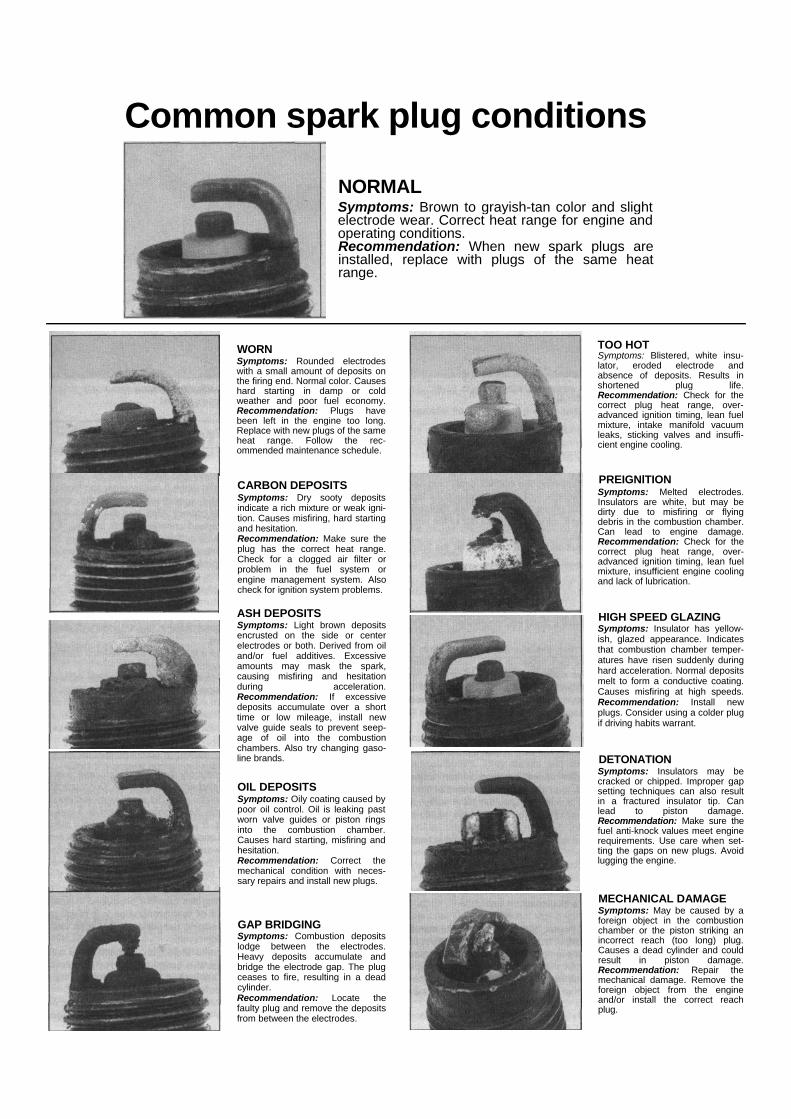
NORMAL Symptoms: Brown to grayish-tan color and slight electrode wear. Correct heat range for engine and operating conditions. Recommendation: When new spark plugs are installed, replace with plugs of the same heat range.
TOO HOT Symptoms: Blistered, white insu-lator, eroded electrode and absence of deposits. Results in shortened plug life. Recommendation: Check for the correct plug heat range, over-advanced ignition timing, lean fuel mixture, intake manifold vacuum leaks, sticking valves and insuffi-cient engine cooling.
WORN Symptoms: Rounded electrodes with a small amount of deposits on the firing end. Normal color. Causes hard starting in damp or cold weather and poor fuel economy. Recommendation: Plugs have been left in the engine too long. Replace with new plugs of the same heat range. Follow the rec-ommended maintenance schedule.
PREIGNlTIONSymptoms: Melted electrodes. Insulators are white, but may be dirty due to misfiring or flying debris in the combustion chamber. Can lead to engine damage. Recommendation: Check for the correct plug heat range, over-advanced ignition timing, lean fuel mixture, insufficient engine cooling and lack of lubrication.
CARBON DEPOSITSSymptoms: Dry sooty deposits indicate a rich mixture or weak igni-tion. Causes misfiring, hard starting and hesitation. Recommendation: Make sure the plug has the correct heat range. Check for a clogged air filter or problem in the fuel system or engine management system. Also check for ignition system problems.
ASH DEPOSITS Symptoms: Light brown deposits encrusted on the side or center electrodes or both. Derived from oil and/or fuel additives. Excessive amounts may mask the spark, causing misfiring and hesitation during acceleration. Recommendation: If excessive deposits accumulate over a short time or low mileage, install new valve guide seals to prevent seep-age of oil into the combustion chambers. Also try changing gaso-line brands.
HIGH SPEED GLAZINGSymptoms: Insulator has yellow-ish, glazed appearance. Indicates that combustion chamber temper-atures have risen suddenly during hard acceleration. Normal deposits melt to form a conductive coating. Causes misfiring at high speeds. Recommendation: Install new plugs. Consider using a colder plug if driving habits warrant.
DETONATIONSymptoms: Insulators may be cracked or chipped. Improper gap setting techniques can also result in a fractured insulator tip. Can lead to piston damage. Recommendation: Make sure the fuel anti-knock values meet engine requirements. Use care when set-ting the gaps on new plugs. Avoid lugging the engine.
OIL DEPOSITS Symptoms: Oily coating caused by poor oil control. Oil is leaking past worn valve guides or piston rings into the combustion chamber. Causes hard starting, misfiring and hesitation. Recommendation: Correct the mechanical condition with neces-sary repairs and install new plugs.
MECHANICAL DAMAGESymptoms: May be caused by a foreign object in the combustion chamber or the piston striking an incorrect reach (too long) plug. Causes a dead cylinder and could result in piston damage. Recommendation: Repair the mechanical damage. Remove the foreign object from the engine and/or install the correct reach plug.
GAP BRIDGING Symptoms: Combustion deposits lodge between the electrodes. Heavy deposits accumulate and bridge the electrode gap. The plug ceases to fire, resulting in a dead cylinder. Recommendation: Locate the faulty plug and remove the deposits from between the electrodes.

Chapter 1 Tune-up and routine maintenance 1-16
not altered (see illustration). Note: A Honda service tool is available which allows the adjuster screw to be held securely while the locknut is tightened. Carry out the check on the other pair of valves. 10 Rotate the crankshaft clockwise until the T2.4 mark is aligned with the rear crankcase joint, then all clearances on No 2 cylinder. 11 Rotate the crankshaft clockwise to align the T1.3 mark once again and check the valves of No 3 cylinder. 12 Rotate the crankshaft further clockwise and align the T2.4 mark, then check the valves of No 4 cylinder. 13 When all clearances have been checked and if necessary adjusted, install the valve covers (see Chapter 2). 14 Fit a new gasket to the left side engine cover, install the cover and tighten its bolts securely. Top up the engine oil. 15 Install the spark plugs. 16 Install the radiator (see Chapter 3) and refill the cooling system with fresh coolant and bleed it of air (see Section 20). On 1986 1100 Magna models, reconnect the radiator (see Chapter 3) and check that its hoses are securely clamped. Turn the radiator tap to ON. Check the level of coolant, topping it up if necessary. Bleed the cooling system of air (see Section 20). 17 Install the fuel tank (see Chapter 4). 18 Start the engine and check that there is no sign of oil leakage from the valve covers.
1986 through 1988 700/750 Magna models 19 Shut off the tap at the radiator bottom hose union and release coolant pressure by momentarily loosening the coolant drain plug set in the subframe. Disconnect the radiator side mountings and its top and bottom hoses, disconnect its wiring, then pivot the radiator forwards about its top mounting point; tie it to the forks out of the way of the front cylinder (see Section 20). 20 On 1987 and 1988 models, pull off its wires and unbolt the horn from the left frame tube. 21 Remove all four spark plugs. 22 Remove the valve cover bolts and lift off both valve covers, plus the rear cylinder valve cover base (see Chapter 2). 23 Remove the alternator cover from the left side of the engine. Note that oil will run from the cover so have a drain tray positioned to catch the oil. 24 Rotate the crankshaft by turning the alternator rotor bolt in a clockwise direction until the intake cam lobes of No 3 cylinder (see illustration 1.1 in Chapter 2 for cylinder identification) are at maximum lift (valves fully depressed). In this position, check the clearances on the intake valves of cylinder No 1. 25 Check and adjust the valve clearances as described in Steps 8 and 9 above. 26 Rotate the alternator bolt further clockwise until the intake cam lobes of No 1 cylinder are at maximum lift, then check the clearances of No 3 intake valves. 27 Rotate the alternator bolt clockwise until the exhaust cam lobes of No 3 cylinder are at maximum lift, then check the clearances of No 1 exhaust valves. Further rotate the crankshaft until the No 1 exhaust cam lobes are a maximum lift and check the clearances of No 3 exhaust valves. 28 Repeat the same procedure to check the clearances of the front cylinders (Nos 2 and 4). 29 When all clearances have been checked and if necessary adjusted, install the valve covers (see Chapter 2). 30 Fit a new gasket to the left side engine cover, install the cover and tighten its bolts securely. Top up the engine oil. 31 Install the spark plugs. 32 Reconnect the radiator (see Chapter 3) and check that its hoses are securely clamped. Turn the radiator tap to ON. Check the level of coolant, topping it up if necessary. Bleed the cooling system of air (see Section 20). 33 Install the fuel tank (see Chapter 4). 34 Start the engine and check that there is no sign of oil leakage from the valve covers.
17.3 Idle speed adjuster (arrow)
17 Idle speed - check and adjustment
Refer to illustration 17.3 1 The idle speed should be checked and adjusted before and after the carburetors are synchronized and when it is obviously too high or too low. Before adjusting the idle speed, make sure the valve clearances and spark plug gaps are correct. Also, turn the handlebars back-and-forth and see if the idle speed changes as this is done. If it does, the throttle cables may not be adjusted correctly, or may be worn out. This is a dangerous condition that can cause loss of control of the bike. Be sure to correct this problem before proceeding. 2 The engine should be at normal operating temperature, which is usually reached after 10 to 15 minutes of stop and go riding. Place the motorcycle on its stand and make sure the transmission is in Neutral. 3 Turn the idle speed screw, located at the base of the No 1 cylinder carburetor until the idle speed listed in this Chapter's Specifications is obtained (see illustration). 4 Snap the throttle open and shut a few times, then recheck the idle speed. If necessary, repeat the adjustment procedure. 5 If a smooth, steady idle can't be achieved, the fuel/air mixture may be incorrect. Refer to Chapter 4 for additional carburetor information.
18 Carburetor synchronization - check and adjustment
Warning: Gasoline (petrol) is extremely flammable, so take extra precautions when you work on any part of the fuel system. Don't smoke or allow open flames or bare light bulbs near the work area, and don't work in a garage where a natural gas-type appliance (such as a water heater or clothes dryer) is present. If you spill any fuel on your skin, rinse it off immediately with soap and water. When you perform any kind of work on the fuel system, wear safety glasses and have a fire extinguisher suitable for a Class B type fire (flammable liquids) on hand. 1 Carburetor synchronization is simply the process of adjusting the carburetors so they pass the same amount of fuel/air mixture to each cylinder. This is done by measuring the vacuum produced in each cylinder. Carburetors that are out of synchronization will result in decreased fuel mileage, increased engine temperature, less than ideal throttle response and higher vibration levels. 2 To properly synchronize the carburetors, you will need some sort of vacuum gauge setup, preferably with a gauge for each cylinder, or a mercury manometer, which is a calibrated tube arrangement that utilizes columns of mercury to indicate engine vacuum. 3 A manometer can be purchased from a motorcycle dealer or accessory shop and should have the necessary screw-in adaptors

Chapter 1 Tune-up and routine maintenance
1-17
18.8 Carburetor synchronization adapter plugs are located in intake tracts (arrow)
18.12 Synchronization screw for No 3 carburetor (arrow)
supplied with it for hooking into the intake tract of the engine. 4 A vacuum gauge setup can also be purchased from a dealer or fabricated from commonly available hardware and automotive vacuum gauges. 5 The manometer is the more reliable and accurate instrument, and for that reason is preferred over the vacuum gauge setup; however, since the mercury used in the manometer is a liquid, and extremely toxic, extra precautions must be taken during use and storage of the instrument. 6 Because of the nature of the synchronization procedure and the need for special instruments, most owners leave the task to a dealer service department or a reputable motorcycle repair shop. 7 Start the engine and let it run until it reaches normal operating temperature. Check the idle speed and adjust if necessary, then shut it off.
700/750 Sabres, 1987 and 1988 700/750 Magna models Refer to illustration 18.8 8 On Sabre models, remove the plugs from the No 2, 3 and 4 cylinder intake tracts, and on Magna models remove the plugs from the No 1, 3 and 4 cylinder intake tracts (see illustration). Install the vacuum gauge or manometer adaptors into the intake tract plug holes, then hook up the vacuum gauge set or the manometer according to the manufacturer's instructions. Make sure there are no air leaks in the set up, as false readings will result. 9 Start the engine and clamp the vacuum line running between the automatic fuel valve and the No 1 (Sabre) or No 2 (Magna) cylinder head intake tract, then stop the engine and disconnect the vacuum line from the fitting on the cylinder head. Connect the remaining line from the vacuum gauge or manometer to this fitting.
All other models 10 Remove the plugs from the intake tracts on all cylinders, install the adaptors into the plug holes and connect up the vacuum gauges or manometer to the adaptors. Make sure there are no air leaks in the set up, as false readings will result.
All models Refer to illustration 18.12 11 Start the engine and check that the idle speed is correct, adjusting it if necessary. If the gauges are fitted with damping adjustment, set this so that the needle flutter is just eliminated but so that they can still respond to small changes in pressure. 12 The vacuum readings for all of the cylinders should be the same, or at least within the tolerance listed in this Chapter's Specifications. If
the vacuum readings vary, adjust as necessary. First locate the adjusting screws; the adjusting screw for No 3 carburetor is next to the throttle stop screw, whereas those for Nos 2 and 4 carburetors are located in-between the carburetor bodies - all are accessed from underneath (see illustration). Note: Wo 1 carburetor has no adjustment screw and should be regarded as the base setting. 13 Adjust each screw until all carburetors are synchronized, then open and close the throttle quickly to settle the linkage and recheck the gauge readings, re-adjusting if necessary. Note: Do not press down on the screws while adjusting them, otherwise a false reading will be obtained. 14 When the adjustment is complete, recheck the idle speed, then stop the engine. Remove the vacuum gauge or manometer and adaptors, then install the intake tract plugs. On 700/750 Sabres and 1987 and 1988 700/750 Magnas, remove the clamp from the fuel valve line and reconnect the line to the fitting on the No 1 (Sabre) or No 2 (Magna) carburetor.
19 Cooling system - check
Warning: The engine must be cool before beginning this procedure. 1 Check the coolant level as described in Section 3. 2 The entire cooling system should be checked for evidence of leakage. Examine each rubber coolant hose along its entire length. Look for cracks, abrasions and other damage. Squeeze each hose at various points. They should feel firm, yet pliable, and return to their original shape when released. If they are dried out or hard, replace them with new ones. 3 Check for evidence of leaks at each cooling system joint. Tighten the hose clips carefully to prevent future leaks. Similarly, check the coolant crossover pipes between the cylinder banks, the coolant inlet pipe on the left side of the engine, and the subframe connections with the radiator and water pump short hose. 4 Check the radiator for leaks and other damage. Leaks in the radiator leave telltale scale deposits or coolant stains on the outside of the core below the leak. If leaks are noted, remove the radiator (see Chapter 3) and have it repaired at a radiator shop or replace it with a new one. Caution: Do not use a liquid leak stopping compound to try to repair leaks. 5 Check the radiator fins for mud, dirt and insects, which may impede the flow of air through the radiator. If the fins are dirty, force water or low pressure compressed air through the fins from the backside. If the fins are bent or distorted, straighten them carefully with a screwdriver. 6 Remove the radiator cap by turning it counterclockwise (anticlockwise) until it reaches a stop. If you hear a hissing sound

Chapter 1 Tune-up and routine maintenance
1-18
20.2 Coolant drain plug in subframe (right arrow) and in water pump cover (left arrow)
20.4 Coolant drain plugs in engine case (arrows)
(indicating there is still pressure in the system), wait until it stops. Now press down on the cap and continue turning the cap until it can be removed. Check the condition of the coolant in the system. If it is rust-colored or if accumulations of scale are visible, drain, flush and refill the system with new coolant (see Section 20). Check the cap seal for cracks and other damage. If in doubt about the pressure cap's condition, have it tested by a dealer service department or replace it with a new one. Install the cap by turning it clockwise until it reaches the first stop then push down on the cap and continue turning until it can turn further. 7 Check the antifreeze content of the coolant with an antifreeze hydrometer. Sometimes coolant looks like it's in good condition, but might be too weak to offer adequate protection. If the hydrometer indicates a weak mixture, drain, flush and refill the system (see Section 20). 8 Start the engine and let it reach normal operating temperature, then check for leaks again. As the coolant temperature increases, the fan should come on automatically and the temperature should begin to drop. If it does not, refer to Chapter 3 and check the fan and fan circuit carefully. 9 If the coolant level is consistently low, and no evidence of leaks can be found, have the entire system pressure checked by a Honda dealer service department, motorcycle repair shop or service station.
20 Cooling system - draining, flushing and refilling
Warning: Allow the engine to cool completely before performing this maintenance operation. Also, don't allow antifreeze to come into contact with your skin or the painted surfaces of the motorcycle. Rinse off spills immediately with plenty of water. Antifreeze is highly toxic if ingested. Never leave antifreeze lying around in an open container or in puddles on the floor; children and pets are attracted by its sweet smell and may drink it. Check with local authorities (councils) about disposing of antifreeze. Many communities have collection centers which will see that antifreeze is disposed of safely. Antifreeze is also combustible, so don't store it near open flames.
Draining Refer to illustrations 20.2 and 20.4 1 With the engine cold place the motorcycle on the main stand on level ground. Where no main stand is fitted, ensure that the motorcycle is supported in an upright position. Remove the belly fairing on 1987 and 1988 700/750 Magna models (see Chapter 6) and on all models, remove the engine rear cover on the left side (see Chapter 2). 2 Place a suitable container under the coolant drain bolt located in
the subframe near the gearshift lever and remove the drain bolt to drain the coolant from the radiator (see illustration). 3 Remove the radiator cap by turning it counterclockwise (anticlockwise) until it reaches a stop. If you hear a hissing sound (indicating there is still pressure in the system), wait until it stops. Now press down on the cap and continue turning the cap until it can be removed. As the cap is removed the flow of coolant will increase, be prepared for this. 4 Drain coolant from the engine by removing the coolant drain bolt at the water pump and the two drain bolts in the front of the engine case (see illustration). 5 When the system is fully drained, replace all drain bolts. 6 Drain the coolant reservoir. Refer to Chapter 3 for reservoir removal procedure. Wash out the reservoir with water and install it.
Flushing 7 Flush the system with clean tap water by inserting a garden hose in the radiator filler neck. Allow the water to run through the system until it is clear and flows cleanly out of both drain holes. If the radiator is extremely corroded, remove it by referring to Chapter 3 and have it cleaned at a radiator shop. 8 Clean the holes then install the drain bolts and sealing washers, tightening them securely. 9 Fill the cooling system with clean water mixed with a flushing compound. Make sure the flushing compound is compatible with aluminum components, and follow the manufacturer's instructions carefully. 10 Start the engine and allow it reach normal operating temperature. Let it run for about ten minutes. 11 Stop the engine. Let it cool for a while, then cover the pressure cap with a heavy shop towel and turn it counterclockwise (anticlockwise) to the first stop, releasing any pressure that may be present in the system. Once the hissing stops, push down on the cap and remove it completely. 12 Drain the system once again. 13 Fill the system with clean water and repeat the procedure in Steps 10 to 12.
Refilling 14 Fit new sealing washers to the drain bolts and install them in the engine case, pump cover and subframe, tightening each one securely. 15 Fill the system with the proper coolant mixture (see this Chapter's Specifications) until it is level with the lower edge of the filler neck. Filling it slowly will reduce the amount of air trapped in the system and lessen the time required to bleed it. 16 Remove the rubber cap from the bleed nipple on the thermostat housing and attach a clear plastic hose to it. Place the other end into a

Chapter 1 Tune-up and routine maintenance 1-19
20.22 1986 through 1988 models have tap in radiator outlet 21.2 Remove plug to drain crankcase separator tank on later models
clean container, such as the one used for draining the coolant. 17 Start the engine and let it idle until it reaches normal operating temperature. Watch the level of the coolant in the radiator and if it drops, add more coolant. 18 Loosen the bleed nipple and observe the coolant running through the hose for air bubbles. Let the engine run until no more air bubbles can be seen in the coolant escaping the tube, then tighten the bleed nipple. Keep checking the coolant level in the radiator, adding more when necessary. The coolant emptied into the container can be poured back into the radiator if the bleed nipple is temporarily tightened while this is being done. When the bleeding procedure is complete, stop the engine and fill the radiator to the bottom of the filler neck one more time, then reinstall the radiator cap. 19 Check the level of coolant in the reservoir tank and, with the coolant hot, fill it to the Upper mark. As a final step, ride the motorcycle for a couple of miles and then recheck the coolant level one last time. Install the engine rear cover and on 1987 and 1988 700/750 Magna models also install the belly fairing. 20 Check the system for leaks and rectify them immediately. 21 Do not dispose of the old coolant by pouring it down the drain. Instead pour it into a heavy plastic container, cap it tightly and take it into an authorized disposal site or service station - see Warning at the beginning of this Section.
Radiator tap Refer to illustration 20.22 22 1986 through 1988 models are equipped with a tap at the radiator outlet union (see illustration). If the radiator requires removal for access to the front cylinder components, full draining of the radiator and lower coolant pipes can be avoided by shutting off the tap in the direction indicated by its arrows. 23 Having shut the tap, loosen and then tighten the coolant drain bolt in the subframe (see illustration 20.2) to release pressure. The radiator can be pivoted forwards about its top mounting after removal of the side mounting bolts and disconnection of the radiator hoses. 24 On installation, ensure that all hose connections are securely made, and open the radiator tap.
21 Crankcase breather - check
Refer to illustration 21.2 1 On 700/750 Sabres and 1982 through 1984 700/750 Magnas, drain any sludge from the crankcase breather tank at the specified interval. 2 Disengage the drain hose from its bracket, hold it over a container
and remove the plug from its end (see illustration). After the deposits have drained, install the plug and secure the hose in its bracket. Note that the crankcase breather is likely to require draining more often if the motorcycle is used at high speeds or in the rain. The transparent drain hose will any build up to be seen at a glance. 3 Check the crankcase breather hoses which run from the rear of the crankcase to the separator tank and from the separator tank to the air filter housing. Replace them if cracked or damaged. 4 On 1100 models and later 700/750 Magnas, there is no drain hose facility on the crankcase breather. For the purpose of routine maintenance, check that the hoses from the breather to the crankcase and air filter housing are not cracked or deteriorated and that they are securely fastened to their unions. If the separator tank is suspected of blockage at any time, disconnect its hoses and drain off any fluid.
22 Evaporative emission control system and Secondary air supply system (California models only) - check
1 The Evaporative emission control system (installed from 1984-on) routes fuel vapors from the fuel system into the engine to be burned, instead of letting them evaporate into the atmosphere. When the engine isn't running, vapors are stored in a carbon canister. The Secondary air supply system (installed from 1986-on) introduces fresh air into the exhaust ports to promote the burning of any excess fuel present in the exhaust gases, reducing that which passes into the atmosphere. Both systems and their components are described in greater detail in Chapter 4. 2 Refer to Chapter 4 for component location details, and inspect the hoses between each system component, replacing them if split or cracked. If any require replacement, take note of their exact routing and connections before removal. Check the emission system canister located on the subframe crosstube for cracks or damage.
23 Exhaust system - check
1 Periodically check all of the exhaust system joints for leaks and loose fasteners. The belly fairing will have to be removed to do this properly on 1987 and 1988 700/750 Magna models (see Chapter 6). If tightening the fasteners fails to stop any leaks, replace the gaskets with new ones (see Chapter 4). 2 The exhaust pipe flange nuts at the cylinder heads are especially prone to loosening, which could cause damage to the head. Check them frequently and keep them tight.

Chapter 1 Tune-up and routine maintenance 1-20
24.4 Feeling for play in the steering head bearings 26.13 Fuel filter takes the form of a gauze element on 700/750 Sabres and 1987/88 Magnas
24 Steering head bearings - check and adjustment
1 This vehicle is equipped with caged taper-roller or caged ball type steering head bearings which can become dented, rough or loose during normal use of the machine. In extreme cases, worn or loose steering head bearings can cause steering wobble - a condition that is potentially dangerous.
Check Refer to illustration 24.4 2 To check the bearings, place the motorcycle on its main stand and block the machine so the front wheel is in the air. On 1987 and 1988 700/750 Magna models, block the vehicle under the crankcase so that the front wheel is raised off the ground. 3 Point the wheel straight-ahead and slowly move the handlebars from side-to-side. Dents or roughness in the bearing races will be felt and the bars will not move smoothly. 4 Next, grasp the fork sliders and try to move them forward and backward (see illustration). Any looseness in the steering head bearings will be felt as front-to-rear movement of the forks, although make sure that this is not due to worn fork bushings. If play is felt in the bearings, adjust the steering head as follows.
Adjustment 5 Refer to Chapter 6 'Steering stem - removal and installation' and remove the upper triple clamp from the forks and steering stem. The forks can remain in place, although the handlebars and instruments must be removed. The upper triple clamp need only be raised sufficiently to access the steering stem locknut and adjuster nuts, so the ignition switch (1982 through 1986 models) can remain attached to the triple clamp if the wiring will allow. 6 Free the lockwasher tabs from the steering stem locknut and adjuster nut, remove the locknut and lockwasher, then carry out adjustment of the adjuster nut as described under the installation sub-Section of Section 10, Chapter 6. 7 After adjustment, check that all steering play has been removed as described above.
25 Fasteners - check
1 Since vibration of the machine tends to loosen fasteners, all nuts, bolts, screws, etc. should be periodically checked for proper tightness. 2 Pay particular attention to the following:
Spark plugs Engine oil drain plugs
Gearshift lever Footpegs, stand bolts Engine mounting bolts Shock absorber mounting bolts Handlebar and triple clamp pinch bolts Rear suspension linkage bolts (Sabres) Front axle and clamp bolts Rear axle nut and clamp bolt Exhaust system bolts/nuts
3 If a torque wrench is available, use it along with the torque specifi-cations at the beginning of this, or other, Chapters.
26 Fuel system - checks and filter replacement
Warning: Gasoline (petrol) is extremely flammable, so take extra precautions when you work on any part of the fuel system. Don't smoke or allow open flames or bare light bulbs near the work area, and don't work in a garage where a natural gas-type appliance (such as a water heater or clothes dryer) is present. If you spill any fuel on your skin, rinse it off immediately with soap and water. When you perform any kind of work on the fuel system, wear safety glasses and have, a fire extinguisher suitable for a Class B type fire (flammable liquids) on hand.
Check 1 Check the fuel tank, the tank breather hose (not California models), the fuel tap, the lines and the carburetors for leaks and evidence of damage. 2 If the carburetor gaskets are leaking, the carburetors should be disassembled and rebuilt by referring to Chapter 4. 3 If the fuel tap is leaking, tightening the retaining nut may help but if leakage persists, the tap should be disassembled and repaired or replaced with a new one (see Chapter 4). 4 If the fuel lines are cracked or otherwise deteriorated, replace them with new ones. 5 On 700/750 Sabres and 1987 and 1988 700/750 Magnas, check the vacuum line connecting the fuel diaphragm valve to No 1 (Sabre) or No 2 (Magna) cylinder intake tract. If it is cracked or otherwise damaged, replace it with a new one.
Filter replacement (1982 through 1986 Magnas and 1100 Sabres) 6 An in-line fuel filter is fitted, which must be replaced at the specified interval.

Chapter 1 Tune-up and routine maintenance 1-21
700/750 Magna models 7 On 1982 through 1984 Magnas, remove the right side cover and turn the fuel valve Off; the filter is located below the valve and to the rear of the battery. On later models turn the fuel valve on the tank Off, then remove the left side cover; the fuel filter is located just above the fuel pump. 8 Release the filter from its holder, clamp the fuel lines each side of the filter, then release the hose clips and pull the hoses off the filter. 9 Install the new filter in the same position as the original, push on the hoses and secure with the clips. Clamp the filter in place, turn the fuel valve On and check that there are no leaks. 1100 models 10 On Sabre models, remove the right side cover (see Chapter 6) and turn the fuel valve Off. On Magna models, remove the seat and left side cover (see Chapter 6). Turn the fuel valve Off. 11 Release the single screw which retains the filter clamp to the fuel valve mounting bracket (Sabre) or frame (Magna). Clamp the fuel lines each side of the filter, then release the hose clips and pull the hoses off the filter. 12 Install the new filter in the same position as the original, push on the hoses and secure with the clips. Clamp the filter in place, turn the fuel valve On and check that there are no leaks.
Filter cleaning (700/75O Sabres, 1987 and 1988 700/750 Magnas) Refer to illustration 26.13 13 A gauze type stack filter is fitted inside the fuel tank as part of the fuel valve. Cleaning is not specified as a maintenance item, but if problems with fuel restriction or fuel contamination are noted it should be removed for cleaning (see illustration). 14 Remove the fuel valve and clean the filter (see Chapter 4).
27 Suspension - check
Front suspension 1 The suspension components must be maintained in top operating condition to ensure rider safety. Loose, worn or damaged suspension parts decrease the vehicle's stability and control. 2 While standing alongside the motorcycle, apply the front brake and push on the handlebars to compress the forks several times. See if they move up-and-down smoothly without binding. If binding is felt, the forks should be disassembled and inspected as described in Chapter 6. 3 Carefully inspect the area around the fork seals for any signs of fork oil leakage. If leakage is evident, the seals must be replaced as described in Chapter 6. 4 Check the tightness of all suspension nuts and bolts to be sure none have worked loose. 5 Where applicable, check the fork air pressure, anti-dive setting and damping setting (see Chapter 6) to ensure that they suit the riding
style and load carried. 6 Fork oil replacement is not specified as a maintenance item, but fork oil will degrade in time with loss of damping performance. Renew the oil periodically (see Chapter 6).
Rear suspension 7 Inspect the rear shock(s) for fluid leakage and tightness of the mounting nuts. If leakage is found, the shock should be replaced. 8 Set the bike on its main stand, or support it securely where no main stand is fitted. Grab the swingarm on each side, just ahead of the axle. Rock the swingarm from side to side - there should be no discernible movement at the rear. If there's a little movement or a slight clicking can be heard, make sure the pivot shaft locknut is tight (see Chapter 6). If the pivot nut is tight but movement is still noticeable, the swingarm will have to be removed and the bearings replaced as described in Chapter 6. 9 Inspect the tightness of the rear suspension linkage nuts and bolts on Sabre models. 10 Where applicable, check the preload and damping settings to ensure that they suit the riding style and load carried (see Chapter 6).
28 Stands - check
Refer to illustration 28.2 1 Check that the side and main stands are mounted securely and that their return springs are not stretched or damaged. 2 The side stand has a wear pad attached to its foot which must be replaced when worn down to the wear line indicated by the moulded arrow (see illustration).
28.2 Side stand rubber wear limit is indicated by arrow