Embed Size (px)
Citation preview
nic
oforal
isin
ares
ndl
Thetemsel
d-er
rendds
on
dlytonnalndeal
CHAPTER 1
INTRODUCTION TO MARINE NAVIGATION
DEFINITIONS
100. The Art And Science Of Navigation
Marine navigation blends both science and art. A goodnavigator constantly thinks strategically, operationally, andtactically. He plans each voyage carefully. As it proceeds,he gathers navigational information from a variety ofsources, evaluates this information, and determines hisship’s position. He then compares that position with hisvoyage plan, his operational commitments, and his pre-determined “dead reckoning” position. A good navigatoranticipates dangerous situations well before they arise, andalways stays “ahead of the vessel.” He is ready for naviga-tional emergencies at any time. He is increasingly amanager of a variety of resources--electronic, mechanical,and human. Navigation methods and techniques vary withthe type of vessel, the conditions, and the navigator’sexperience. The navigator uses the methods and techniquesbest suited to the vessel, its equipment, and conditions athand.
Some important elements of successful navigationcannot be acquired from any book or instructor. The scienceof navigation can be taught, but the art of navigation mustbe developed from experience.
101. Types of Navigation
Methods of navigation have changed throughouthistory. New methods often enhance the mariner’s ability tocomplete his voyage safely and expeditiously, and make hisjob easier. One of the most important judgments thenavigator must make involves choosing the best methods touse. Each method or type has advantages anddisadvantages, while none is effective in all situations.Commonly recognized types of navigation are listed below.
• Dead reckoning (DR) determines position byadvancing a known position for courses anddistances. A position so determined is called a deadreckoning (DR) position. It is generally accepted thatonly course and speed determine the DR position.Correcting the DR position for leeway, currenteffects, and steering error result in anestimatedposition (EP).
• Piloting involves navigating in restricted waters
with frequent or constant determination of positiorelative to nearby geographic and hydrographfeatures.
• Celestial navigation involves reducing celestialmeasurements taken with a sextant to linesposition using calculators or computer programs,by hand with almanacs and tables or using spherictrigonometry.
• Radio navigation uses radio waves to determineposition through a variety of electronic devices.
• Radar navigation uses radar to determine thedistance from or bearing of objects whose positionknown. This process is separate from radar’s usecollision avoidance.
• Satellite navigation uses radio signals fromsatellites for determining position.
Electronic systems and integrated bridge conceptsdriving navigation system planning. Integrated systemtake inputs from various ship sensors, electronically aautomatically chart the position, and provide controsignals required to maintain a vessel on a preset course.navigator becomes a system manager, choosing syspresets, interpreting system output, and monitoring vesresponse.
In practice, a navigator synthesizes different methoologies into a single integrated system. He should nevfeel comfortable utilizing only one method when others aalso available. Each method has advantages adisadvantages. The navigator must choose methoappropriate to each situation, and never rely completelyonly one system.
With the advent of automated position fixing anelectronic charts, modern navigation is almost completean electronic process. The mariner is constantly temptedrely solely on electronic systems. But electronic navigatiosystems are always subject to failure, and the professiomariner must never forget that the safety of his ship acrew may depend on skills that differ little from thospracticed generations ago. Proficiency in conventionpiloting and celestial navigation remains essential.
1
2 INTRODUCTION TO MARINE NAVIGATION
ixse.for
he
nishnofn.ichre
erre00m
edrsedngtor
ta-edlehes
ey
o.ut
102. Phases of Navigation
Four distinct phases define the navigation process. Themariner should choose the system mix that meets theaccuracy requirements of each phase.
• Inland Waterway Phase: Piloting in narrow canals,channels, rivers, and estuaries.
• Harbor/Harbor Approach Phase: Navigating to aharbor entrance through bays and sounds, andnegotiating harbor approach channels.
• Coastal Phase: Navigating within 50 miles of thecoast or inshore of the 200 meter depth contour.
• Ocean Phase: Navigating outside the coastal area inthe open sea.
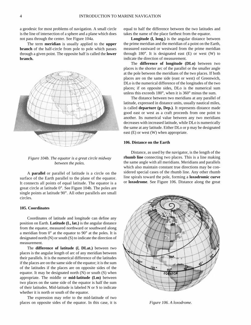
The navigator’s position accuracy requirements, his finterval, and his systems requirements differ in each phaThe following table can be used as a general guideselecting the proper system(s).
NAVIGATION TERMS AND CONVENTIONS
103. Important Conventions and Concepts
Throughout the history of navigation, numerous termsand conventions have been established which enjoyworldwide recognition. The professional navigator, to gaina full understanding of his field, should understand theorigin of certain terms, techniques, and conventions. Thefollowing section discusses some of the important ones.
Defining aprime meridian is a comparatively recentdevelopment. Until the beginning of the 19th century, therewas little uniformity among cartographers as to themeridian from which to measure longitude. But it matteredlittle because there existed no method for determininglongitude accurately.
Ptolemy, in the 2nd century AD, measured longitudeeastward from a reference meridian 2 degrees west of theCanary Islands. In 1493, Pope Alexander VI established aline in the Atlantic west of the Azores to divide theterritories of Spain and Portugal. For many years, cartog-raphers of these two countries used this dividing line as theprime meridian. In 1570 the Dutch cartographer Orteliusused the easternmost of the Cape Verde Islands. JohnDavis, in his 1594The Seaman’s Secrets, used the Isle ofFez in the Canaries because there the variation was zero.Most mariners paid little attention to these conventions andoften reckoned their longitude from several different capesand ports during a voyage.
The meridian of London was used as early as 1676, andover the years its popularity grew as England’s maritimeinterests increased. The system of measuring longitude botheast and west through 180° may have first appeared in themiddle of the 18th century. Toward the end of that century,as the Greenwich Observatory increased in prominence,English cartographers began using the meridian of that
observatory as a reference. The publication by tObservatory of the first BritishNautical Almanacin 1767further entrenched Greenwich as the prime meridian. Aunsuccessful attempt was made in 1810 to establWashington, D.C. as the prime meridian for Americanavigators and cartographers. In 1884, the meridianGreenwich was officially established as the prime meridiaToday, all maritime nations have designated the Greenwmeridian the prime meridian, except in a few cases whelocal references are used for certain harbor charts.
Charts are graphic representations of areas of thEarth, in digital or graphic form, for use in marine or ainavigation. Nautical charts, whether in digital or papeform, depict features of particular interest to the marinnavigator. Charts have probably existed since at least 6B.C. Stereographic and orthographic projections date frothe 2nd century B.C. In 1569 Gerardus Mercator publisha chart using the mathematical principle which now beahis name. Some 30 years later, Edward Wright publishcorrected mathematical tables for this projection, enabliother cartographers to produce charts on the Mercaprojection. This projection is still the most widely used.
Sailing Directionsor pilotshave existed since at leasthe 6th century B.C. Continuous accumulation of navigtional data, along with increased exploration and trade, lto increased production of volumes through the MiddAges. “Routiers” were produced in France about 1500; tEnglish referred to them as “rutters.” In 1584 LucaWaghenaer published theSpieghel der Zeevaerdt (TheMariner’s Mirror) , which became the model for suchpublications for several generations of navigators. Thwere known as “Waggoners” by most sailors.
The compasswas developed about 1000 years agThe origin of the magnetic compass is uncertain, b
Inland Harbor/Approach
Coastal Ocean
DR X X X XPiloting X X XCelestial X XRadio X X XRadar X X XSatellite X* X X X
Table 102. The relationship of the types and phases ofnavigation. * With SA off and/or using DGPS
INTRODUCTION TO MARINE NAVIGATION 3
e00n
he
-y
es,ebyd
rendy.a
’sth
danof aeatato
is.
Norsemen used it in the 11th century, and Chinesenavigators used the magnetic compass at least that early andprobably much earlier. It was not until the 1870s that LordKelvin developed a reliable dry card marine compass. Thefluid-filled compass became standard in 1906.
Variation was not understood until the 18th century,when Edmond Halley led an expedition to map lines ofvariation in the South Atlantic.Deviation was understoodat least as early as the early 1600s, but adequate correctionof compass error was not possible until Matthew Flindersdiscovered that a vertical iron bar could reduce certaintypes of errors. After 1840, British Astronomer Royal SirGeorge Airy and later Lord Kelvin developedcombinations of iron masses and small magnets toeliminate most magnetic compass error.
The gyrocompasswas made necessary by iron andsteel ships. Leon Foucault developed the basic gyroscope in1852. An American (Elmer Sperry) and a German (AnshutzKampfe) both developed electrical gyrocompasses in theearly years of the 20th century. Ring laser gyrocompassesand digital flux gate compasses are gradually replacingtraditional gyrocompasses, while the magnetic compassremains an important backup device.
The log is the mariner’s speedometer. Marinersoriginally measured speed by observing a chip of woodpassing down the side of the vessel. Later developmentsincluded a wooden board attached to a reel of line. Marinersmeasured speed by noting how many knots in the lineunreeled as the ship moved a measured amount of time;hence the termknot. Mechanical logs using either a smallpaddle wheel or a rotating spinner arrived about the middleof the 17th century. The taffrail log still in limited use todaywas developed in 1878. Modern logs use electronic sensorsor spinning devices that induce small electric fields propor-tional to a vessel’s speed. An engine revolution counter orshaft log often measures speed aboard large ships. Dopplerspeed logs are used on some vessels for very accurate speedreadings. Inertial and satellite systems also provide highlyaccurate speed readings.
The Metric Conversion Act of 1975 and the OmnibusTrade and Competitiveness Act of 1988 established themetric system of weights and measures in the UnitedStates. As a result, the government is converting charts tothe metric format. Notwithstanding the conversion to themetric system, the common measure of distance at sea is thenautical mile.
The current policy of the National Imagery andMapping Agency (NIMA) and the National OceanService (NOS) is to convert new compilations ofnautical, special purpose charts, and publications to themetric system. All digital charts use the metric system.This conversion began on January 2, 1970. Most modernmaritime nations have also adopted the meter as thestandard measure of depths and heights. However, oldercharts still on issue and the charts of some foreigncountries may not conform to this standard.
The fathom as a unit of length or depth is of obscurorigin. Posidonius reported a sounding of more than 1,0fathoms in the 2nd century B.C. How old the unit was theis unknown. Many modern charts are still based on tfathom, as conversion to the metric system continues.
The sailings refer to various methods of mathematically determining course, distance, and position. Thehave a history almost as old as mathematics itself. ThalHipparchus, Napier, Wright, and others contributed thformulas that permit computation of course and distanceplane, traverse, parallel, middle latitude, Mercator, angreat circle sailings.
104. The Earth
The Earth is an irregular oblate spheroid (a spheflattened at the poles). Measurements of its dimensions athe amount of its flattening are subjects of geodesHowever, for most navigational purposes, assumingspherical Earth introduces insignificant error. The Earthaxis of rotation is the line connecting the north and sougeographic poles.
A great circle is the line of intersection of a sphere ana plane through its center. This is the largest circle that cbe drawn on a sphere. The shortest line on the surfacesphere between two points on the surface is part of a grcircle. On the spheroidal Earth the shortest line is calledgeodesic. A great circle is a near enough approximation
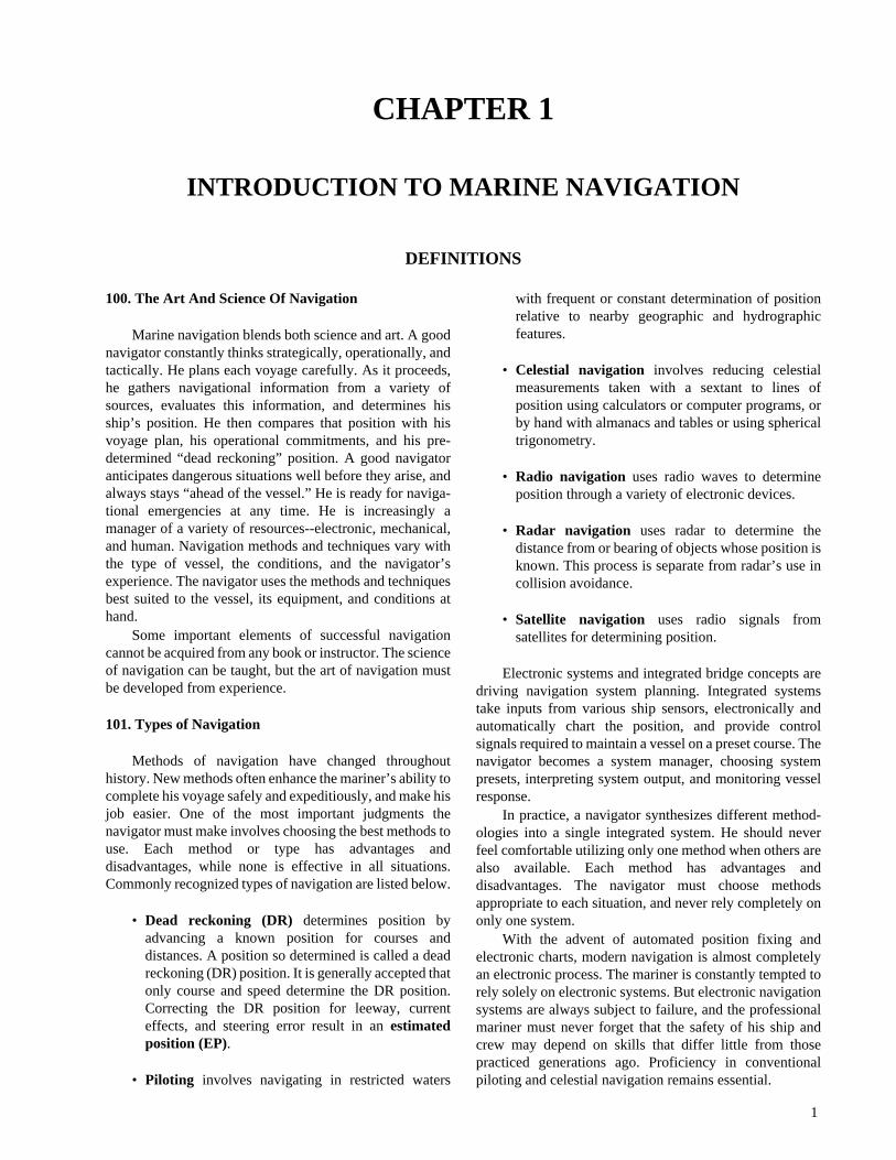
Figure 104a. The planes of the meridians at the polar ax
4 INTRODUCTION TO MARINE NAVIGATION
nd
nth,ian
gleth
ich,om
ofes,e
tonsllyted
heglsn-b
at
a geodesic for most problems of navigation. A small circleis the line of intersection of a sphere and a plane which doesnot pass through the center. See Figure 104a.
The termmeridian is usually applied to theupperbranch of the half-circle from pole to pole which passesthrough a given point. The opposite half is called thelowerbranch.
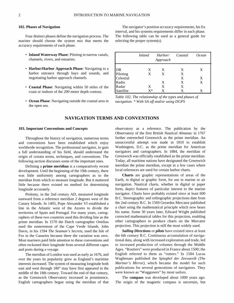
A parallel or parallel of latitude is a circle on thesurface of the Earth parallel to the plane of the equator.It connects all points of equal latitude. The equator is agreat circle at latitude 0°. See Figure 104b. Thepoles aresingle points at latitude 90°. All other parallels are smallcircles.
105. Coordinates
Coordinates of latitude and longitude can define anyposition on Earth.Latitude (L, lat.) is the angular distancefrom the equator, measured northward or southward alonga meridian from 0° at the equator to 90° at the poles. It isdesignated north (N) or south (S) to indicate the direction ofmeasurement.
The difference of latitude (l, DLat.) between twoplaces is the angular length of arc of any meridian betweentheir parallels. It is the numerical difference of the latitudesif the places are on the same side of the equator; it is the sumof the latitudes if the places are on opposite sides of theequator. It may be designated north (N) or south (S) whenappropriate. The middle ormid-latitude (Lm) betweentwo places on the same side of the equator is half the sumof their latitudes. Mid-latitude is labeled N or S to indicatewhether it is north or south of the equator.
The expression may refer to the mid-latitude of twoplaces on opposite sides of the equator. In this case, it is
equal to half the difference between the two latitudes atakes the name of the place farthest from the equator.
Longitude (l, long.) is the angular distance betweethe prime meridian and the meridian of a point on the Earmeasured eastward or westward from the prime meridthrough 180°. It is designated east (E) or west (W) toindicate the direction of measurement.
The difference of longitude (DLo) between twoplaces is the shorter arc of the parallel or the smaller anat the pole between the meridians of the two places. If boplaces are on the same side (east or west) of GreenwDLo is the numerical difference of the longitudes of the twplaces; if on opposite sides, DLo is the numerical suunless this exceeds 180°, when it is 360° minus the sum.
The distance between two meridians at any parallellatitude, expressed in distance units, usually nautical milis calleddeparture (p, Dep.). It represents distance madgood east or west as a craft proceeds from one pointanother. Its numerical value between any two meridiadecreases with increased latitude, while DLo is numericathe same at any latitude. Either DLo or p may be designaeast (E) or west (W) when appropriate.
106. Distance on the Earth
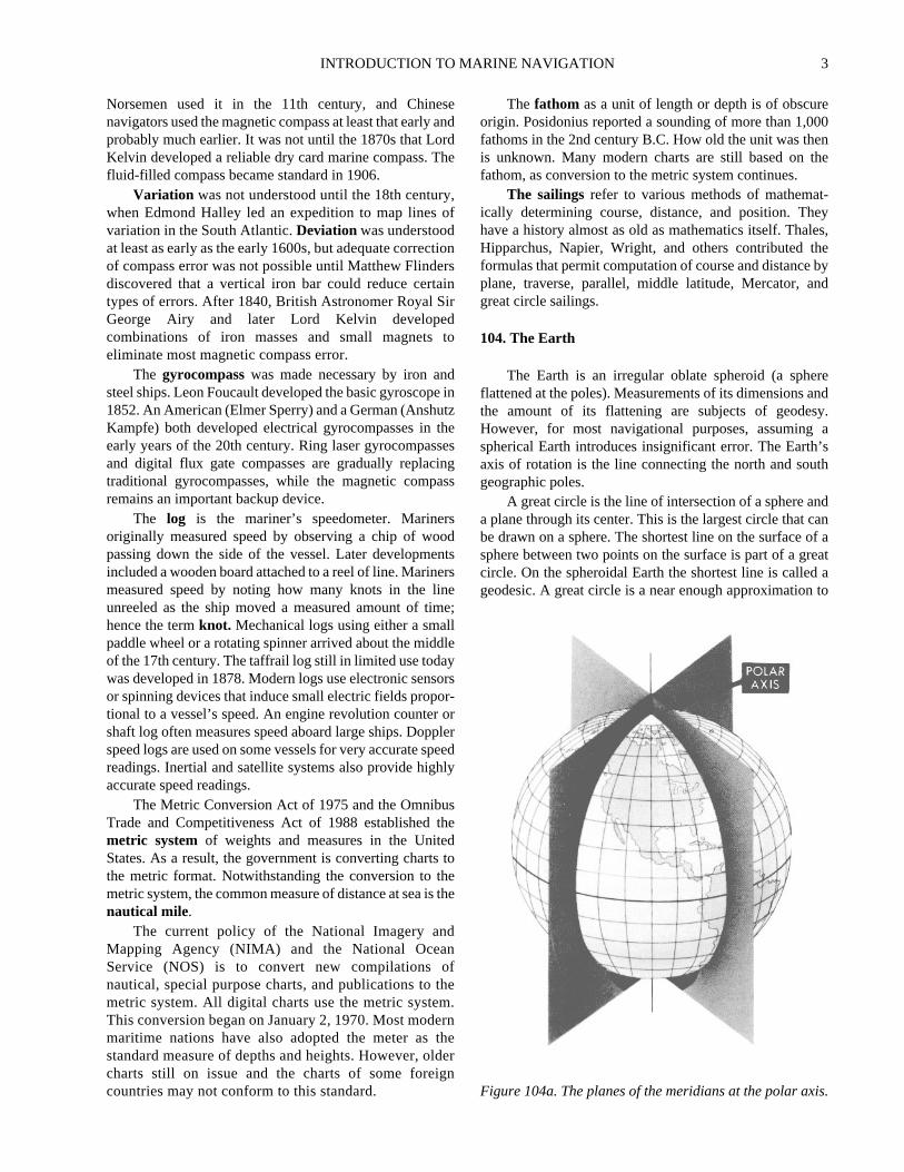
Distance, as used by the navigator, is the length of trhumb line connecting two places. This is a line makinthe same angle with all meridians. Meridians and parallewhich also maintain constant true directions may be cosidered special cases of the rhumb line. Any other rhumline spirals toward the pole, forming aloxodromic curveor loxodrome. See Figure 106. Distance along the gre
Figure 104b. The equator is a great circle midwaybetween the poles.
Figure 106. A loxodrome.
INTRODUCTION TO MARINE NAVIGATION 5
ate).
lndeee
ngsel
cle
lar
s assea,
om
sedthemve
-
-
circle connecting two points is customarily designatedgreat-circle distance. For most purposes, considering thenautical mile the length of one minute of latitude introducesno significant error
Speed (S)is rate of motion, or distance per unit of time.A knot (kn.), the unit of speed commonly used innavigation, is a rate of 1 nautical mile per hour. Theexpressionspeed of advance (SOA)is used to indicate thespeed to be made along the intended track.Speed over theground (SOG) is the actual speed of the vessel over thesurface of the Earth at any given time. To calculatespeedmade good (SMG) between two positions, divide thedistance between the two positions by the time elapsedbetween the two positions.
107. Direction on the Earth
Direction is the position of one point relative toanother. Navigators express direction as the angulardifference in degrees from a reference direction, usuallynorth or the ship’s head.Course (C, Cn) is the horizontaldirection in which a vessel is intended to be steered,expressed as angular distance from north clockwise through360°. Strictly used, the term applies to direction through thewater, not the direction intended to be made good over theground.Thecourse is often designated as true, magnetic,compass, or grid according to the reference direction.
Track made good (TMG) is the single resultantdirection from the point of departure to point of arrival atany given time.Course of advance (COA)is the directionintended to be made good over the ground, andcourse overground (COG) is the direction between a vessel’s last fixand an EP. Acourse line is a line drawn on a chartextending in the direction of a course. It is sometimesconvenient to express a course as an angle from either north
or south, through 90° or 180°. In this case it is designatedcourse angle (C) and should be properly labeled to indicthe origin (prefix) and direction of measurement (suffixThus, C N35°E = Cn 035° (000° + 35°), C N155°W = Cn205° (360° - 155°), C S47°E = Cn 133° (180° - 47°). But Cn260° may be either C N100°W or C S80°W, dependingupon the conditions of the problem.
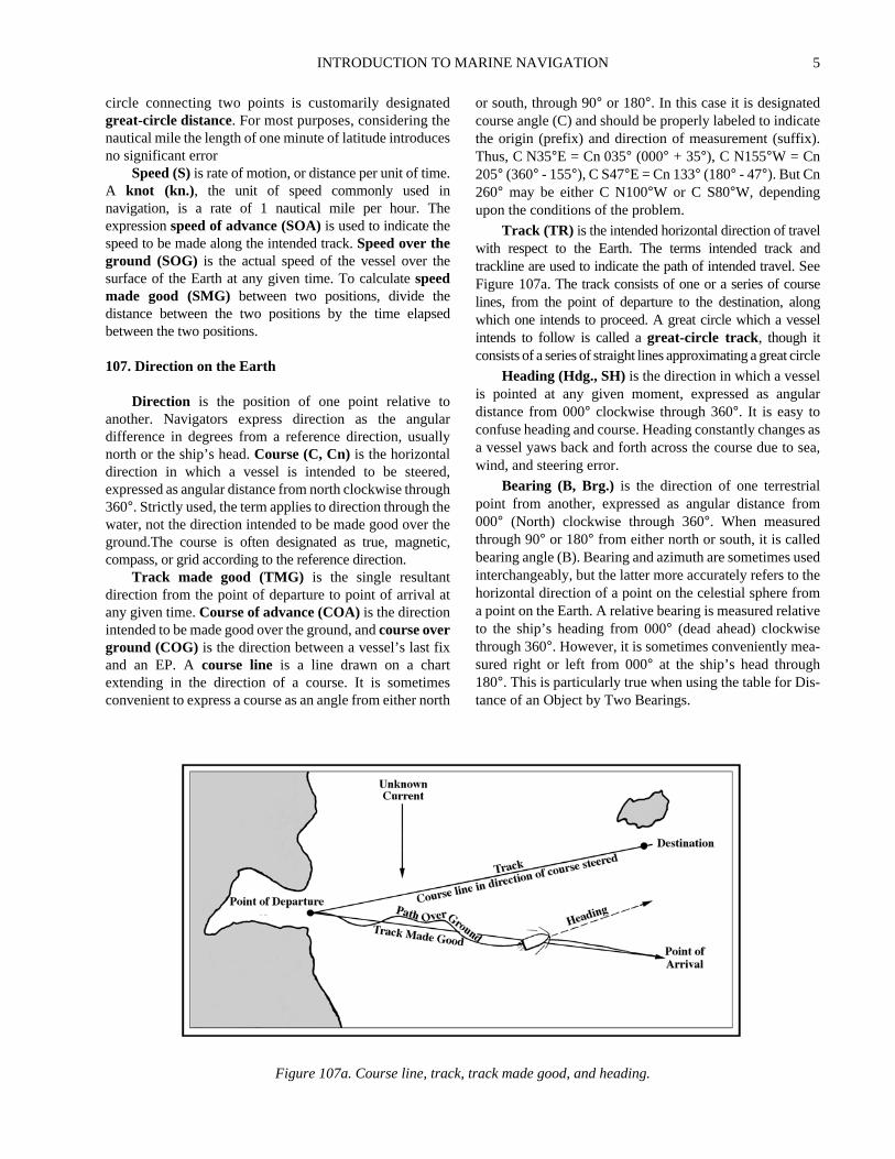
Track (TR) is the intended horizontal direction of travewith respect to the Earth. The terms intended track atrackline are used to indicate the path of intended travel. SFigure 107a. Thetrack consists of one or a series of courslines, from the point of departure to the destination, alowhich one intends to proceed. A great circle which a vesintends to follow is called agreat-circle track, though itconsists of a series of straight lines approximating a great cir
Heading (Hdg., SH)is the direction in which a vesselis pointed at any given moment, expressed as angudistance from 000° clockwise through 360°. It is easy toconfuse heading and course. Heading constantly changea vessel yaws back and forth across the course due towind, and steering error.
Bearing (B, Brg.) is the direction of one terrestrialpoint from another, expressed as angular distance fr000° (North) clockwise through 360°. When measuredthrough 90° or 180° from either north or south, it is calledbearing angle (B). Bearing and azimuth are sometimes uinterchangeably, but the latter more accurately refers tohorizontal direction of a point on the celestial sphere froa point on the Earth. A relative bearing is measured relatito the ship’s heading from 000° (dead ahead) clockwisethrough 360°. However, it is sometimes conveniently measured right or left from 000° at the ship’s head through180°. This is particularly true when using the table for Distance of an Object by Two Bearings.
Figure 107a. Course line, track, track made good, and heading.

6 INTRODUCTION TO MARINE NAVIGATION
on
of
s,in
terlstond
ial
thelar
greearndo
sece
thenedthethethe
To convert a relative bearing to a true bearing, add thetrue heading. See Figure 107b
True Bearing = Relative Bearing + True Heading.Relative Bearing = True Bearing - True Heading.
108. Finding Latitude and Longitude
Navigators have made latitude observations forthousands of years. Accurate declination tables for the Sunhave been published for centuries, enabling ancient seamento compute latitude to within 1 or 2 degrees. Those whotoday determine their latitude by measuring the Sun at theirmeridian and the altitude of Polaris are using methods wellknown to 15th century navigators.
A method of finding longitude eluded mariners forcenturies. Several solutions independent of time proved toocumbersome. Finding longitude by magnetic variation wastried, but found too inaccurate. The lunar distance method,which determines GMT by observing the Moon’s positionamong the stars, became popular in the 1800s. However,the mathematics required by most of these processes werefar above the abilities of the average seaman. It wasapparent that the solution lay in keeping accurate time atsea.
In 1714, the British Board of Longitude was formed,offering a small fortune in reward to anyone who couldprovide a solution to the problem.
An Englishman, John Harrison, responded to thechallenge, developing four chronometers between 1735 and1760. The most accurate of these timepieces lost only 15seconds on a 156 day round trip between London andBarbados. The Board, however, paid him only half thepromised reward. The King finally intervened on
Harrison’s behalf, and at the age of 80 years Harrisreceived his full reward of £20,000.
Rapid chronometer development led to the problemdeterminingchronometer error aboard ship.Time balls,large black spheres mounted in port in prominent locationwere dropped at the stroke of noon, enabling any shipharbor which could see the ball to determine chronomeerror. By the end of the U.S. Civil War, telegraph signawere being used to key time balls. Use of radio signalssend time ticks to ships well offshore began in 1904, asoon worldwide signals were available.
109. The Navigational Triangle
Modern celestial navigators reduce their celestobservations by solving anavigational triangle whosepoints are the elevated pole, the celestial body, andzenith of the observer. The sides of this triangle are the podistance of the body (codeclination), its zenith distance(coaltitude), and the polar distance of the zenith (colatitudeof the observer).
A spherical triangle was first used at sea in solvinlunar distance problems. Simultaneous observations wemade of the altitudes of the Moon and the Sun or a star nthe ecliptic and the angular distance between the Moon athe other body. The zenith of the observer and the twcelestial bodies formed the vertices of a triangle whosides were the two coaltitudes and the angular distanbetween the bodies. Using a mathematical calculationnavigator “cleared” this distance of the effects of refractioand parallax applicable to each altitude. This correctvalue was then used as an argument for enteringalmanac. The almanac gave the true lunar distance fromSun and several stars at 3 hour intervals. Previously,
Figure 107b. Relative Bearing
INTRODUCTION TO MARINE NAVIGATION 7
try,ed
e.beceereed.m
tory asoint
ndon, a
navigator had set his watch or checked its error and ratewith the local mean time determined by celestialobservations. The local mean time of the watch, properlycorrected, applied to the Greenwich mean time obtainedfrom the lunar distance observation, gave the longitude.
The calculations involved were tedious. Few marinerscould solve the triangle until Nathaniel Bowditch publishedhis simplified method in 1802 inThe New AmericanPractical Navigator.
Reliable chronometers were available by1800, but theirhigh cost precluded their general use aboard most ships.However, most navigators could determine their longitudeusing Bowditch’s method. This eliminated the need forparallel sailing and the lost time associated with it. Tables forthe lunar distance solution were carried in the Americannautical almanac into the 20th century.
110. The Time Sight
The theory of thetime sight had been known to math-
ematicians since the development of spherical trigonomebut not until the chronometer was developed could it be usby mariners.
The time sight used the modern navigational trianglThe codeclination, or polar distance, of the body coulddetermined from the almanac. The zenith distan(coaltitude) was determined by observation. If thcolatitude were known, three sides of the triangle weavailable. From these the meridian angle was computThe comparison of this with the Greenwich hour angle frothe almanac yielded the longitude.
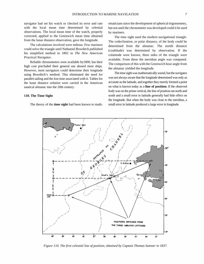
The timesightwasmathematically sound,but thenavigawas not always aware that the longitude determined was onlaccurate as the latitude, and together they merely formed a pon what is known today as aline of position. If the observedbody was on the prime vertical, the line of position ran north asouth and a small error in latitude generally had little effectthe longitude. But when the body was close to the meridiansmall error in latitude produced a large error in longitude.
Figure 110. The first celestial line of position, obtained by Captain Thomas Sumner in 1837.

8 INTRODUCTION TO MARINE NAVIGATION
ersixerte-
yheby
rnith
s.edllyirst9
esalarit
on
oine
dio07he
theindtlic
ofndedeseble
em
The line of position by celestial observation was un-known until discovered in 1837 by 30-year-old CaptainThomas H. Sumner, a Harvard graduate and son of a UnitedStates congressman from Massachusetts. The discovery ofthe “Sumner line,” as it is sometimes called, was consid-ered by Maury “the commencement of a new era in practicalnavigation.” This was the turning point in the developmentof modern celestial navigation technique. In Sumner’s ownwords, the discovery took place in this manner:
Having sailed from Charleston, S. C., 25th Novem-ber, 1837, bound to Greenock, a series of heavy galesfrom the Westward promised a quick passage; after pass-ing the Azores, the wind prevailed from the Southward,with thick weather; after passing Longitude 21° W, no ob-servation was had until near the land; but soundings werehad not far, as was supposed, from the edge of the Bank.The weather was now more boisterous, and very thick;and the wind still Southerly; arriving about midnight,17th December, within 40 miles, by dead reckoning, ofTusker light; the wind hauled SE, true, making the Irishcoast a lee shore; the ship was then kept close to the wind,and several tacks made to preserve her position as nearlyas possible until daylight; when nothing being in sight,she was kept on ENE under short sail, with heavy gales;at about 10 AM an altitude of the Sun was observed, andthe Chronometer time noted; but, having run so far with-out any observation, it was plain the Latitude by deadreckoning was liable to error, and could not be entirelyrelied on. Using, however, this Latitude, in finding theLongitude by Chronometer, it was found to put the ship15' of Longitude E from her position by dead reckoning;which in Latitude 52° N is 9 nautical miles; this seemed toagree tolerably well with the dead reckoning; but feelingdoubtful of the Latitude, the observation was tried with aLatitude 10' further N, finding this placed the ship ENE27 nautical miles, of the former position, it was triedagain with a Latitude 20' N of the dead reckoning; thisalso placed the ship still further ENE, and still 27 nauticalmiles further; these three positions were then seen to liein the direction of Small’s light. Itthen at once appearedthat the observed altitude must have happened at allthe three points, and at Small’s light, and at the ship,at the same instant of time; and it followed, thatSmall’s light must bear ENE, if the Chronometerwas right. Having been convinced of this truth, theship was kept on her course, ENE, the wind being stillSE., and in less than an hour, Small’s light was madebearing ENE 1/2 E, and close aboard.
In 1843 Sumner published a book, ANew and AccurateMethod of Finding a Ship’s Position at Sea by Projectionon Mercator’s Chart. He proposed solving a single timesight twice, using latitudes somewhat greater and somewhatless than that arrived at by dead reckoning, and joining thetwo positions obtained to form the line of position.
The Sumner method required the solution of two timsights to obtain each line of position. Many older navigatopreferred not to draw the lines on their charts, but to ftheir position mathematically by a method which Sumnhad also devised and included in his book. This was adious but popular procedure.
111. Navigational Tables
Spherical trigonometry is the basis for solving evernavigational triangle, and until about 80 years ago tnavigator had no choice but to solve each triangletedious, manual computations.
Lord Kelvin, generally considered the father of modenavigational methods, expressed interest in a book of tables wwhich a navigator could avoid tedious trigonometric solutionHowever, solving the many thousands of triangles involvwould have made the project too costly. Computers finaprovided a practical means of preparing tables. In 1936 the fvolume ofPub. No. 214was made available; later, Pub. No. 24was provided for air navigators.Pub. No. 229,Sight ReductionTables for Marine Navigation, has replacedPub. No. 214.
Electronic calculators are gradually replacing thtables. Scientific calculators with trigonometric functioncan easily solve the navigational triangle. Navigationcalculators readily solve celestial sights and performvariety of voyage planning functions. Using a calculatogenerally gives more accurate lines of position becauseeliminates the rounding errors inherent in tabular inspectiand interpolation.
112. Development of Electronic Navigation
Perhaps the first application of electronics tnavigation involved sending telegraphic time signals1865 to check chronometer error. Transmitting radio timsignals for chronometer checks dates to 1904. Rabroadcasts providing navigational warnings, begun in 19by the U.S. Navy Hydrographic Office, helped increase tsafety of navigation at sea.
By the latter part of World War I the directionalproperties of a loop antenna were successfully used inradio direction finder. The first radiobeacon was installed1921. Early 20th century experiments by Behm anLangevin led to the U.S. Navy’s development of the firspractical echo sounder in 1922. Radar and hyperbosystems grew out of WWII.
Today, electronics touches almost every aspectnavigation. Hyperbolic systems, satellite systems, aelectronic charts all require an increasingly sophisticatelectronics suite and the expertise to manage them. Thsystems’ accuracy and ease of use make them invaluaassets to the navigator, but there is far more to using ththan knowing which buttons to push.

INTRODUCTION TO MARINE NAVIGATION 9
alte
s
ofan
ble
derwoler-ldormanem
ofst
ofardork
uslyalehin
thhat
f
ticanns
91ndans.stns,ts
113. Development of Radar
As early as 1904, German engineers were experimentingwith reflected radio waves. In 1922 two American scientists,Dr. A. Hoyt Taylor and Leo C. Young, testing a communi-cation system at the Naval Aircraft Radio Laboratory, notedfluctuations in the signals when ships passed between stationson opposite sides of the Potomac River. In 1935 the Britishbegan work on radar. In 1937 the USS Leary tested the firstsea-going radar, and in 1940 United States and Britishscientists combined their efforts. When the British revealed theprinciple of the multicavity magnetron developed by J. T.Randall and H. A. H. Boot at the University of Birmingham in1939, microwave radar became practical. In 1945, at the closeof World War II, radar became available for commercial use.
114. Development of Hyperbolic Radio Aids
Various hyperbolic systems were developed beginningin World War II. These were outgrowths of the British GEEsystem, developed to help bombers navigate to and fromtheir missions over Europe. Loran A was developed as along-range marine navigation system. This was replaced bythe more accurate Loran C system, deployed throughout
much of the world. Various short range and regionhyperbolic systems have been developed by privaindustry for hydrographic surveying, offshore facilitiepositioning, and general navigation.
115. Other Electronic Systems
The underlying concept that led to developmentsatellite navigation dates to 1957 and the first launch ofartificial satellite into orbit. The first system, NAVSAT, hasbeen replaced by the far more accurate and widely availaGlobal Positioning System (GPS), which has revolu-tionized all aspects of navigation
The first inertial navigation system was developed in1942 for use in the V2 missile by the Peenemunde group unthe leadership of Dr. Wernher von Braun. This system used t2-degree-of-freedom gyroscopes and an integrating acceometer to determine the missile velocity. By the end of WorWar II, the Peenemunde group had developed a stable platfwith three single-degree-of-freedom gyroscopes andintegrating accelerometer. In 1958 an inertial navigation systwas used to navigate the USSNautilus under the ice to theNorth Pole.
NAVIGATION ORGANIZATIONS
116. Governmental Role
Navigation only a generation ago was an independentprocess, carried out by the mariner without outsideassistance. With compass and charts, sextant andchronometer, he could independently travel anywhere inthe world. The increasing use of electronic navigationsystems has made the navigator dependent on many factorsoutside his control. Government organizations fund,operate, and regulate satellites, Loran, and other electronicsystems. Governments are increasingly involved inregulation of vessel movements through traffic controlsystems and regulated areas. Understanding the govern-mental role in supporting and regulating navigation isvitally important to the mariner. In the United States, thereare a number of official organizations which support theinterests of navigators. Some have a policy-making role;others build and operate navigation systems. Manymaritime nations have similar organizations performingsimilar functions. International organizations also play asignificant role.
117. The Coast and Geodetic Survey
TheU.S. Coast and Geodetic Surveywas founded in1807 when Congress passed a resolution authorizing asurvey of the coast, harbors, outlying islands, and fishingbanks of the United States. President Thomas Jeffersonappointed Ferdinand Hassler, a Swiss immigrant and
professor of mathematics at West Point, the first Directorthe “Survey of the Coast.” The survey became the “CoaSurvey” in 1836.
The approaches to New York were the first sectionsthe coast charted, and from there the work spread northwand southward along the eastern seaboard. In 1844 the wwas expanded and arrangements made to simultaneochart the gulf and east coasts. Investigation of tidconditions began, and in 1855 the first tables of tidpredictions were published. The California gold rusnecessitated a survey of the west coast, which began1850, the year California became a state.Coast Pilots, orSailing Directions, for the Atlantic coast of the UnitedStates were privately published in the first half of the 19century. In 1850 the Survey began accumulating data tled to federally producedCoast Pilots. The 1889PacificCoast Pilotwas an outstanding contribution to the safety owest coast shipping.
In 1878 the survey was renamed “Coast and GeodeSurvey.” In 1970 the survey became the “National OceSurvey,” and in 1983 it became the “National OceaService.” The Office of Charting and Geodetic Serviceaccomplished all charting and geodetic functions. In 19the name was changed back to the original “Coast aGeodetic Survey,” organized under the National OceService along with several other environmental officeToday it provides the mariner with the charts and coapilots of all waters of the United States and its possessioand tide and tidal current tables for much of the world. I
10 INTRODUCTION TO MARINE NAVIGATION
thefryfof
f
f2,
72e
rt
e.toe
terg
he
ehes
ndase
endInndoneetg
rdedrs;S
es
administrative order requires the Coast and GeodeticSurvey to plan and direct programs to produce charts andrelated information for safe navigation of U.S. waterways,territorial seas, and airspace. This work includes allactivities related to the National Geodetic ReferenceSystem; surveying, charting, and data collection;production and distribution of charts; and research anddevelopment of new technologies to enhance thesemissions.
118. The National Imagery and Mapping Agency
In the first years of the newly formed United States ofAmerica, charts and instruments used by the Navy andmerchant mariners were left over from colonial days orwere obtained from European sources. In 1830 the U.S.Navy established a “Depot of Charts and Instruments” inWashington, D. C., as a storehouse from which availablecharts, pilots and sailing directions, and navigationalinstruments were issued to Naval ships. Lieutenant L. M.Goldsborough and one assistant, Passed Midshipman R. B.Hitchcock, constituted the entire staff.
The first chart published by the Depot was producedfrom data obtained in a survey made by Lieutenant CharlesWilkes, who had succeeded Goldsborough in 1834. Wilkeslater earned fame as the leader of a United States expeditionto Antarctica. From 1842 until 1861 Lieutenant MatthewFontaine Maury served as Officer in Charge. Under hiscommand the Depot rose to international prominence.
Maury decided upon an ambitious plan to increase themariner’s knowledge of existing winds, weather, andcurrents. He began by making a detailed record of pertinentmatter included in old log books stored at the Depot. Hethen inaugurated a hydrographic reporting program amongship masters, and the thousands of reports received, alongwith the log book data, were compiled into the “Wind andCurrent Chart of the North Atlantic” in 1847. This is theancestor of today’sPilot Chart.
The United States instigated an internationalconference in 1853 to interest other nations in a system ofexchanging nautical information. The plan, which wasMaury’s, was enthusiastically adopted by other maritimenations. In 1854 the Depot was redesignated the “U.S.Naval Observatory and Hydrographical Office.” At theoutbreak of the American Civil War in 1861, Maury, anative of Virginia, resigned from the U.S. Navy andaccepted a commission in the Confederate Navy. Thiseffectively ended his career as a navigator, author, andoceanographer. At war’s end, he fled the country, hisreputation suffering from his embrace of the Confederatecause.
After Maury’s return to the United States in 1868, heserved as an instructor at the Virginia Military Institute. Hecontinued at this position until his death in 1873. Since hisdeath, his reputation as one of America’s greatest hydrog-
raphers has been restored.
In 1866 Congress separated the Observatory andHydrographic Office, broadly increasing the functions othe latter. The Hydrographic Office was authorized to carout surveys, collect information, and print every kind onautical chart and publication “for the benefit and usenavigators generally.”
The Hydrographic Office purchased the copyright oThe New American Practical Navigatorin 1867. The firstNotice to Marinersappeared in 1869. Daily broadcast onavigational warnings was inaugurated in 1907. In 191following the sinking of theTitanic, the International IcePatrol was established.
In 1962 the U.S. Navy Hydrographic Office wasredesignated the U.S. Naval Oceanographic Office. In 19certain hydrographic functions of the latter office wertransferred to the Defense Mapping AgencyHydrographic Center. In 1978 theDefense MappingAgency Hydrographic/Topographic Center(DMAHTC) assumed hydrographic and topographic chaproduction functions. In 1996 theNational Imagery andMapping Agency (NIMA) was formed from DMA andcertain other elements of the Department of DefensNIMA continues to produce charts and publications anddisseminate maritime safety information in support of thU.S. military and navigators generally.
119. The United States Coast Guard
Alexander Hamilton established theU.S. CoastGuard as the Revenue Marine, later the Revenue CutService, on August 4, 1790. It was charged with enforcinthe customs laws of the new nation. A revenue cutter, tHarriet Lane, fired the first shot from a naval unit in theCivil War at Fort Sumter. The Revenue Cutter Servicbecame the U.S. Coast Guard when combined with tLifesaving Service in 1915. The Lighthouse Service waadded in 1939, and the Bureau of Marine Inspection aNavigation was added in 1942. The Coast Guard wtransferred from the Treasury Department to thDepartment of Transportation in 1967.
The primary functions of the Coast Guard includmaritime search and rescue, law enforcement, aoperation of the nation’s aids to navigation system.addition, the Coast Guard is responsible for port safety asecurity, merchant marine inspection, and marine polluticontrol. The Coast Guard operates a large and varied flof ships, boats, and aircraft in performing its widely ranginduties
Navigation systems operated by the Coast Guainclude the system of some 40,000 lighted and unlightbeacons, buoys, and ranges in U.S. and territorial watethe U.S. stations of the Loran C system; differential GP(DGPS) services in the U.S.; and Vessel Traffic Servic(VTS) in major ports and harbors of the U.S.
INTRODUCTION TO MARINE NAVIGATION 11
e.t atslyr inns.
hein0,in
a-asaler
forir
eareeirsehee
d-
on
d
der
inr
ys
-
d.
sorbyerin
89,at
120. The United States Navy
The U.S. Navywas officially established in 1798. Itsrole in the development of navigational technology has beensingular. From the founding of the Naval Observatory to thedevelopment of the most advanced electronics, the U.S.Navy has been a leader in developing devices and techniquesdesigned to make the navigator’s job safer and easier.
The development of almost every device known tonavigation science has been deeply influenced by Navalpolicy. Some systems are direct outgrowths of specificNaval needs; some are the result of technologicalimprovements shared with other services and withcommercial maritime industry.
121. The United States Naval Observatory
One of the first observatories in the United States wasbuilt in 1831-1832 at Chapel Hill, N.C. The Depot of Chartsand Instruments, established in 1830, was the agency fromwhich the U.S. Navy Hydrographic Office and theU.S.Naval Observatory evolved 36 years later. In about 1835,under Lieutenant Charles Wilkes, the second Officer inCharge, the Depot installed a small transit instrument forrating chronometers.
The Mallory Act of 1842 provided for theestablishment of a permanent observatory. The director wasauthorized to purchase everything necessary to continueastronomical study. The observatory was completed in1844 and the results of its first observations were publishedtwo years later. Congress established the NavalObservatory as a separate agency in 1866. In 1873 arefracting telescope with a 26 inch aperture, then theworld’s largest, was installed. The observatory, located inWashington, D.C., has occupied its present site since 1893.
122. The Royal Greenwich Observatory
England had no early privately supported observatoriessuch as those on the continent. The need for navigationaladvancement was ignored by Henry VIII and Elizabeth I,but in 1675 Charles II, at the urging of John Flamsteed,Jonas Moore, Le Sieur de Saint Pierre, and ChristopherWren, established theGreenwich Royal Observatory.Charles limited construction costs to £500, and appointedFlamsteed the first Astronomer Royal, at an annual salaryof £100. The equipment available in the early years of theobservatory consisted of two clocks, a “sextant” of 7 footradius, a quadrant of 3 foot radius, two telescopes, and thestar catalog published almost a century before by TychoBrahe. Thirteen years passed before Flamsteed had aninstrument with which he could determine his latitudeaccurately.
In 1690 a transit instrument equipped with a telescopeand vernier was invented by Romer; he later added a verticalcircle to the device. This enabled the astronomer to
determine declination and right ascension at the same timOne of these instruments was added to the equipmenGreenwich in 1721, replacing the huge quadrant previouused. The development and perfection of the chronometethe next hundred years added to the accuracy of observatio
Other national observatories were constructed in tyears that followed: at Berlin in 1705, St. Petersburg1725, Palermo in 1790, Cape of Good Hope in 182Parramatta in New South Wales in 1822, and Sydney1855.
123. The International Hydrographic Organization
The International Hydrographic Organization(IHO) was originally established in 1921 as the Interntional Hydrographic Bureau (IHB). The present name wadopted in 1970 as a result of a revised internationagreement among member nations. However, the formname, International Hydrographic Bureau, was retainedthe IHO’s administrative body of three Directors and thestaff at the organization’s headquarters in Monaco.
The IHO sets forth hydrographic standards to bagreed upon by the member nations. All member statesurged and encouraged to follow these standards in thsurveys, nautical charts, and publications. As thestandards are uniformly adopted, the products of tworld’s hydrographic and oceanographic offices becommore uniform. Much has been done in the field of standarization since the Bureau was founded.
The principal work undertaken by the IHO is:
• To bring about a close and permanent associatibetween national hydrographic offices.
• To study matters relating to hydrography and alliesciences and techniques.
• To further the exchange of nautical charts andocuments between hydrographic offices of membgovernments.
• To circulate the appropriate documents.• To tender guidance and advice upon request,
particular to countries engaged in setting up oexpanding their hydrographic service.
• To encourage coordination of hydrographic survewith relevant oceanographic activities.
• To extend and facilitate the application of oceanographic knowledge for the benefit of navigators.
• To cooperate with international organizations anscientific institutions which have related objectives
During the 19th century, many maritime nationestablished hydrographic offices to provide means fimproving the navigation of naval and merchant vesselsproviding nautical publications, nautical charts, and othnavigational services. There were substantial differenceshydrographic procedures, charts, and publications. In 18an International Marine Conference was held
12 INTRODUCTION TO MARINE NAVIGATION
byted
al30andfore
at isntheify.
inthe
by
8.tsntswinee
ted,estheintofethe
gon
Washington, D. C., and it was proposed to establish a“permanent international commission.” Similar proposalswere made at the sessions of the International Congress ofNavigation held at St. Petersburg in 1908 and again in 1912.
In 1919 the hydrographers of Great Britain and Francecooperated in taking the necessary steps to convene aninternational conference of hydrographers. London wasselected as the most suitable place for this conference, andon July 24, 1919, the First International Conferenceopened, attended by the hydrographers of 24 nations. Theobject of the conference was “To consider the advisabilityof all maritime nations adopting similar methods in thepreparation, construction, and production of their chartsand all hydrographic publications; of rendering the resultsin the most convenient form to enable them to be readilyused; of instituting a prompt system of mutual exchange ofhydrographic information between all countries; and ofproviding an opportunity to consultations and discussionsto be carried out on hydrographic subjects generally by thehydrographic experts of the world.” This is still the majorpurpose of the International Hydrographic Organization.
As a result of the conference, a permanent organizationwas formed and statutes for its operations were prepared. TheInternational Hydrographic Bureau, now the InternationalHydrographic Organization, began its activities in 1921 with18 nations as members. The Principality of Monaco wasselected because of its easy communication with the rest of theworld and also because of the generous offer of Prince AlbertI of Monaco to provide suitable accommodations for theBureau in the Principality. There are currently 59 membergovernments. Technical assistance with hydrographic mattersis available through the IHO to member states requiring it.
Many IHO publications are available to the generalpublic, such as the International Hydrographic Review,International Hydrographic Bulletin, Chart Specificationsof the IHO, Hydrographic Dictionary, and others. Inquiriesshould be made to the International Hydrographic Bureau,7 Avenue President J. F. Kennedy, B.P. 445, MC98011,Monaco, CEDEX.
124. The International Maritime Organization
The International Maritime Organization (IMO)was established by United Nations Convention in 1948. TheConvention actually entered into force in 1959, although aninternational convention on marine pollution was adopted in1954. (Until 1982 the official name of the organization wasthe Inter-Governmental Maritime Consultative Organi-zation.) It is the only permanent body of the U. N. devotedto maritime matters, and the only special U. N. agency tohave its headquarters in the UK.
The governing body of the IMO is theAssembly of137 member states, which meets every two years. BetweenAssembly sessions a Council, consisting of 32 membergovernments elected by the Assembly, governs the organi-zation. Its work is carried out by the Maritime Safety
Committee, with subcommittees for:
• Safety of Navigation• Radiocommunications• Life-saving• Search and Rescue• Training and Watchkeeping• Carriage of Dangerous Goods• Ship Design and Equipment• Fire Protection• Stability and Load Lines/Fishing Vessel Safety• Containers and Cargoes• Bulk Chemicals• Marine Environment Protection Committee• Legal Committee• Technical Cooperation Committee• Facilitation Committee
IMO is headed by the Secretary General, appointedthe council and approved by the Assembly. He is assisby some 300 civil servants.
To achieve its objectives of coordinating internationpolicy on marine matters, the IMO has adopted someconventions and protocols, and adopted over 700 codesrecommendations. An issue to be adopted first is brought bea committee or subcommittee, which submits a draft toconference. When the conference adopts the final text, isubmitted to member governments for ratification. Ratificatioby a specified number of countries is necessary for adoption;more important the issue, the more countries must ratAdopted conventions are binding on member governments.
Codes and recommendations are not binding, butmost cases are supported by domestic legislation bygovernments involved.
The first and most far-reaching convention adoptedthe IMO was the Convention ofSafety of Life at Sea(SOLAS) in 1960. This convention actually came intoforce in 1965, replacing a version first adopted in 194Because of the difficult process of bringing amendmeninto force internationally, none of subsequent amendmebecame binding. To remedy this situation, a neconvention was adopted in 1974 and became binding1980. Among the regulations is V-20, requiring the carriagof up-to-date charts and publications sufficient for thintended voyage.
Other conventions and amendments were also adopsuch as the International Convention on Load Lin(adopted 1966, came into force 1968), a convention ontonnage measurement of ships (adopted 1969, cameforce 1982), The International Convention on SaContainers (adopted 1972, came into force 1977), andconvention onInternational Regulations for PreventingCollisions at Sea (COLREGS)(adopted 1972, came intoforce 1977).
The 1972 COLREGS convention contained, amonother provisions, a section devoted to Traffic Separati
INTRODUCTION TO MARINE NAVIGATION 13
dthe
e-
aed tod
onn.
sn-d
meto
nserofs,s.lopl
d.fety
nghipor
.
innenttedsngheallsg
Schemes, which became binding on member states afterhaving been adopted as recommendations in prior years.
One of the most important conventions is theInterna-tional Convention for the Prevention of Pollution fromShips (MARPOL 73/78), which was first adopted in 1973,amended byProtocol in 1978, andbecame binding in1983. Thisconvention built on a series of prior conventions and agreementsdating from 1954, highlighted by several severe pollutiondisasters involving oil tankers. The MARPOL conventionreduces the amount of oil discharged into the sea by ships, andbans discharges completely in certain areas. A relatedconvention known as the London Dumping Conventionregulates dumping of hazardous chemicals and other debris intothe sea.
The IMO also develops minimum performancestandards for a wide range of equipment relevant to safetyat sea. Among such standards is one for theElectronicChart Display and Information System (ECDIS), thedigital display deemed the operational and legal equivalentof the conventional paper chart.
Texts of the various conventions and recommendations,as well as a catalog and publications on other subjects, areavailable from the Publications Section of the IMO at 4Albert Embankment, London SE1 7SR, United Kingdom.
125. The International Association of Marine Aids toNavigation and Lighthouse Authorities
The International Association of Marine Aids toNavigation and Lighthouse Authorities (formerlyIALA) brings together representatives of the aids tonavigation services of more than 80 member countries fortechnical coordination, information sharing, and coordi-nation of improvements to visual aids to navigationthroughout the world. It was established in 1957 to providea permanent organization to support the goals of theTechnical Lighthouse Conferences, which had beenconvening since 1929. The General Assembly of IALAmeets about every 4 years. The Council of 20 membersmeets twice a year to oversee the ongoing programs.
Five technical committees maintain the permanentprograms:
• The Marine Marking Committee• The Radionavigation Systems Committee• The Vessel Traffic Services (VTS) Committee• The Reliability Committee• The Documentation Committee
IALA committees provide important documentation tothe IHO and other international organizations, while theIALA Secretariat acts as a clearing house for the exchangeof technical information, and organizes seminars andtechnical support for developing countries.
Its principle work since 1973 has been the implemen-tation of the IALA Maritime Buoyage System, described in
Chapter 5, Visual Aids to Navigation. This system replacesome 30 dissimilar buoyage systems in use throughoutworld with 2 major systems.
IALA is based near Paris, France in Saint-Germainen-Laye.
126. The Radio Technical Commission for MaritimeServices
The Radio Technical Commission for MaritimeServices is a non-profit organization which serves asfocal point for the exchange of information and thdevelopment of recommendations and standards relateall aspects of maritime radiocommunications anradionavigation.
Specifically, RTCM:
• Promotes ideas and exchanges informationmaritime radiocommunications and radionavigatio
• Facilitates the development and exchange of viewamong and between government and nogovernment interests both nationally aninternationally.
• Conducts studies and prepares reports on maritiradiocommunications and radionavigation issuesimprove efficiency and capabilities.
Both government and non-government organizatioare members, coming from the U.S. and many othnations. The RTCM organization consists of a BoardDirectors, and the Assembly consisting of all memberofficers, staff, technical advisors, and working committee
Working committees are formed as needed to deveofficial RTCM recommendations regarding technicastandards and regulatory policies in the maritime fielCurrently committees address such issues as maritime sainformation, electronic charts, emergency position-indicatiradiobeacons (EPIRB’s), personal locator beacons, sradars, differential GPS, GLONASS, and maritime survivlocator devices.
The RTCM headquarters office is in Alexandria, VA
127. The National Marine Electronic Association
The National Marine Electronic Association(NMEA) is a professional trade association founded1957 whose purpose is to coordinate the efforts of marielectronics manufacturers, technicians, governmeagencies, ship and boat builders, and other interesgroups. In addition to certifying marine electronictechnicians and professionally recognizing outstandiachievements by corporate and individual members, tNMEA sets standards for the exchange of digital data bymanufacturers of marine electronic equipment. This allowthe configuration of integrated navigation system usinequipment from different manufacturers.
14 INTRODUCTION TO MARINE NAVIGATION
tofer-o
ofensusar,ierd inof
ndto
entd
NMEA works closely with RTCM and other privateorganizations and with government agencies to monitor thestatus of laws and regulations affecting the marineelectronics industry.
It also sponsors conferences and seminars, andpublishes a number of guides and periodicals for membersand the general public.
128. International Electrotechnical Commission
The International Electrotechnical Commission(IEC) was founded in 1906 as an outgrowth of the Interna-tional Electrical Congress held at St. Louis, Missouri in1904. Some 60 countries are active members. Its mission isto develop and promote standardization among all nationsin the technical specifications of electrical and electronicequipment. These technologies include electronics,magnetics, electromagnetics, electroacoustics, multimedia,telecommunications, electrical energy production anddistribution, and associated fields such as terminology andsymbology, compatibility, performance standards, safety,
and environmental factors.
By standardizing in these areas, the IEC seekspromote more efficient markets, improve the quality oproducts and standards of performance, promote interopability, increase production efficiency, and contribute thuman health and safety and environmental protection.
Standards are published by the IEC in the formofficial IEC documents after debate and input from thnational committees. Standards thus represent a conseof the views of many different interests. Adoption ofstandard by any country is entirely voluntary. Howevefailure to adopt a standard may result in a technical barrto trade, as goods manufactured to a proprietary standarone country may be incompatible with the systemsothers.
IEC standards are vital to the success of ECDIS aother integrated navigation systems because they helpensure that systems from various manufacturers in differcountries will be compatible and meet requirespecifications.