Embed Size (px)
Citation preview
Chapter 1 Static Force Analysis
When the inertia forces are neglected in comparison to the externally applied load, one may go for static
force analysis. If the body is under equilibrium condition, then this equilibrium is known as static
equilibrium and this condition is applicable in many machines where the movement is relatively slow.
These include clamps, latches, support linkages, and many hand operated tools, such as pliers and cutters.
In case of lifting cranes also, the bucket load and the static weight loads may be quite high relative to any
dynamic loads due to accelerating masses and hence one may go for static force analysis.
When the inertia effect due to the mass of the components is also considered, it is called dynamic force
analysis.
Applied and Constraint forces:
• When two or more bodies are connected together to form a group or system, the pair of action
and reaction forces between any two of the connecting bodies is called constrained forces.
• These forces constrain the connected bodies to behave in a specific manner defined by the nature
of the connection.
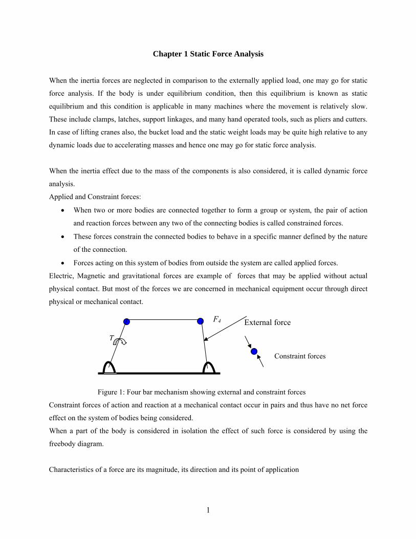
• Forces acting on this system of bodies from outside the system are called applied forces.
Electric, Magnetic and gravitational forces are example of forces that may be applied without actual
physical contact. But most of the forces we are concerned in mechanical equipment occur through direct
physical or mechanical contact.
External force
Constraint forces
T
F4
Figure 1: Four bar mechanism showing external and constraint forces
Constraint forces of action and reaction at a mechanical contact occur in pairs and thus have no net force
effect on the system of bodies being considered.
When a part of the body is considered in isolation the effect of such force is considered by using the
freebody diagram.
Characteristics of a force are its magnitude, its direction and its point of application
1
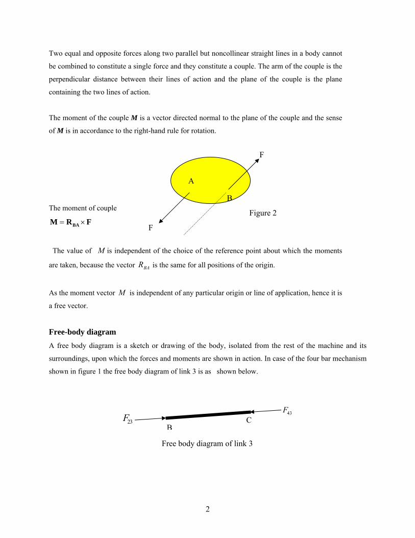
Two equal and opposite forces along two parallel but noncollinear straight lines in a body cannot
be combined to constitute a single force and they constitute a couple. The arm of the couple is the
perpendicular distance between their lines of action and the plane of the couple is the plane
containing the two lines of action.
The moment of the couple M is a vector directed normal to the plane of the couple and the sense
of M is in accordance to the right-hand rule for rotation.
The moment of couple
= ×BAM R F
The value of M is independent of the choice of the reference point about which the moments
are taken, because the vector is the same for all positions of the origin. BAR
As the moment vector M is independent of any particular origin or line of application, hence it is
a free vector.
Figure 2
B
A
F
F
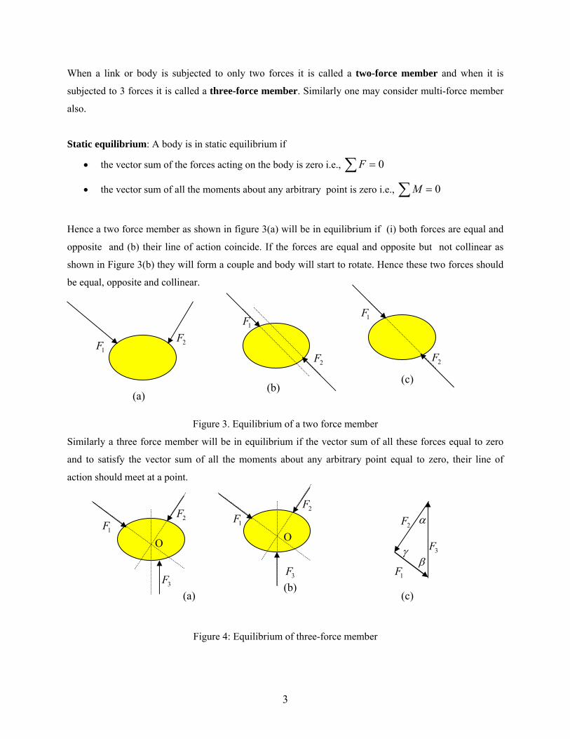
Free-body diagram
A free body diagram is a sketch or drawing of the body, isolated from the rest of the machine and its
surroundings, upon which the forces and moments are shown in action. In case of the four bar mechanism
shown in figure 1 the free body diagram of link 3 is as shown below.
43F 23F C
B
Free body diagram of link 3
2
When a link or body is subjected to only two forces it is called a two-force member and when it is
subjected to 3 forces it is called a three-force member. Similarly one may consider multi-force member
also.
Static equilibrium: A body is in static equilibrium if
• the vector sum of the forces acting on the body is zero i.e., ∑ = 0F
• the vector sum of all the moments about any arbitrary point is zero i.e., ∑ = 0M
Hence a two force member as shown in figure 3(a) will be in equilibrium if (i) both forces are equal and
opposite and (b) their line of action coincide. If the forces are equal and opposite but not collinear as
shown in Figure 3(b) they will form a couple and body will start to rotate. Hence these two forces should
be equal, opposite and collinear.
1F 2F
1F 1F
2F
(c) (b)
(a)
2F
Figure 3. Equilibrium of a two force member
Similarly a three force member will be in equilibrium if the vector sum of all these forces equal to zero
and to satisfy the vector sum of all the moments about any arbitrary point equal to zero, their line of
action should meet at a point.
1F2F
3F (b)
O
(a) 3F
2F 1F
O
α 2F
1F
3F β
γ
(c)
Figure 4: Equilibrium of three-force member
3
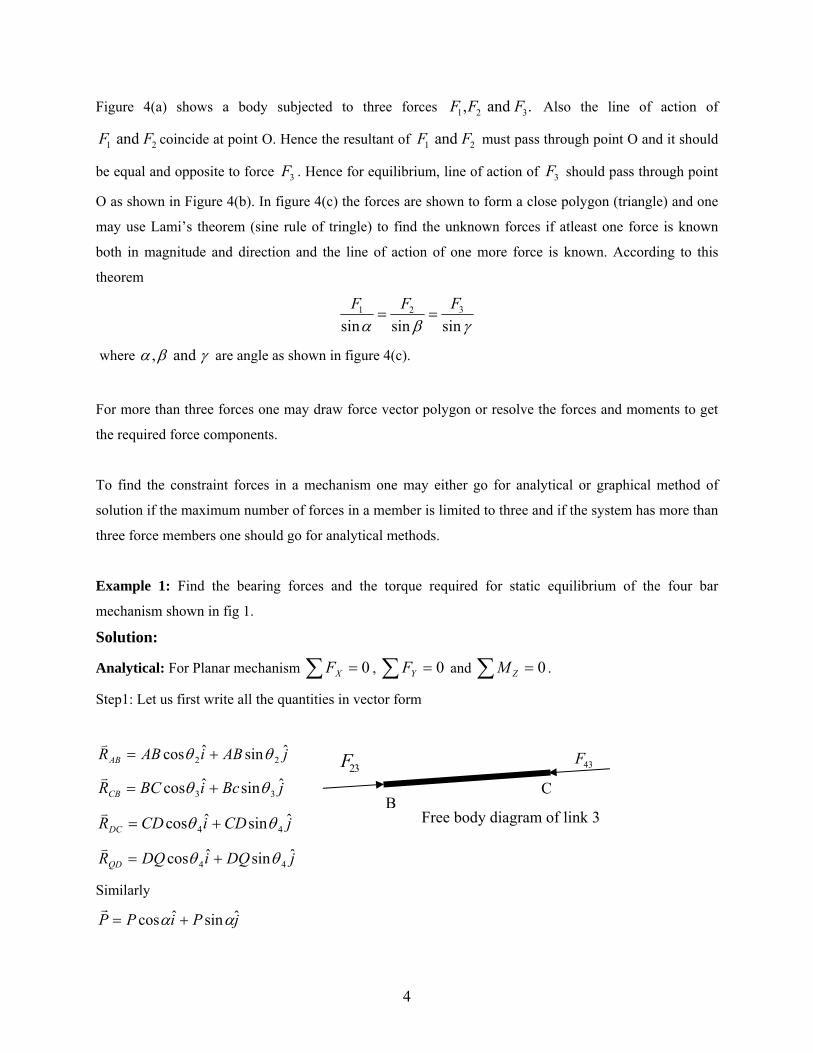
Figure 4(a) shows a body subjected to three forces Also the line of action of
coincide at point O. Hence the resultant of must pass through point O and it should
be equal and opposite to force . Hence for equilibrium, line of action of should pass through point
O as shown in Figure 4(b). In figure 4(c) the forces are shown to form a close polygon (triangle) and one
may use Lami’s theorem (sine rule of tringle) to find the unknown forces if atleast one force is known
both in magnitude and direction and the line of action of one more force is known. According to this
theorem
1 2 3, and .F F F
1 and F 2F 2F1 and F
3F 3F
31 2
sin sin sinFF F
α β γ= =
where , and α β γ are angle as shown in figure 4(c).
For more than three forces one may draw force vector polygon or resolve the forces and moments to get
the required force components.
To find the constraint forces in a mechanism one may either go for analytical or graphical method of
solution if the maximum number of forces in a member is limited to three and if the system has more than
three force members one should go for analytical methods.
Example 1: Find the bearing forces and the torque required for static equilibrium of the four bar
mechanism shown in fig 1.
Solution:
Analytical: For Planar mechanism , 0=∑ XF 0=∑ YF and 0=∑ ZM .
Step1: Let us first write all the quantities in vector form
jABiABRABˆsinˆcos 22 θθ +=
23F 43F
C B
jBciBCRCBˆsinˆcos 33 θθ +=
jCDiCDRDCˆsinˆcos 44 θθ += Free body diagram of link 3
jDQiDQRQDˆsinˆcos 44 θθ +=
Similarly
jPiPP ˆsinˆcos αα +=
4
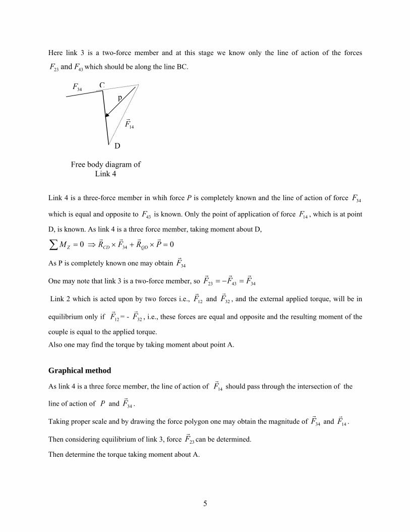
Here link 3 is a two-force member and at this stage we know only the line of action of the forces
which should be along the line BC. 23 43and F F
34F
p
D
14F
C
Free body diagram of
Link 4
Link 4 is a three-force member in whih force P is completely known and the line of action of force
which is equal and opposite to is known. Only the point of application of force , which is at point
D, is known. As link 4 is a three force member, taking moment about D,
34F
43F 14F
0=∑ ZM 034 =×+×⇒ PRFR QDCD
As P is completely known one may obtain 34F
One may note that link 3 is a two-force member, so 344323 FFF =−=
Link 2 which is acted upon by two forces i.e., 12F and 32F , and the external applied torque, will be in
equilibrium only if = - 12F 32F , i.e., these forces are equal and opposite and the resulting moment of the
couple is equal to the applied torque.
Also one may find the torque by taking moment about point A.
Graphical method
As link 4 is a three force member, the line of action of 14F should pass through the intersection of the
line of action of P and 34F .
Taking proper scale and by drawing the force polygon one may obtain the magnitude of 34F and 14F .
Then considering equilibrium of link 3, force 23F can be determined.
Then determine the torque taking moment about A.
5
When multiple forces act on a mechanism, one may use superposition theory, which states that in a
linear system, the net effect (e.g., bearing forces or torque) due to all the forces taken simultaneously will
be equal to the summation of the effects due to individual forces taken one at a time.
If one wishes to find only the torque acting on the mechanism, the method of virtual work may be used. It
states the work performed during a virtual displacement from equilibrium is equal to zero. The
virtual displacement is defined as an imaginary infinitesimal displacement of the system that is consistent
with the constraints on the system. For example, the constraints on the slider-crank mechanism are that all
members including the frame are rigid and all joints maintain contact
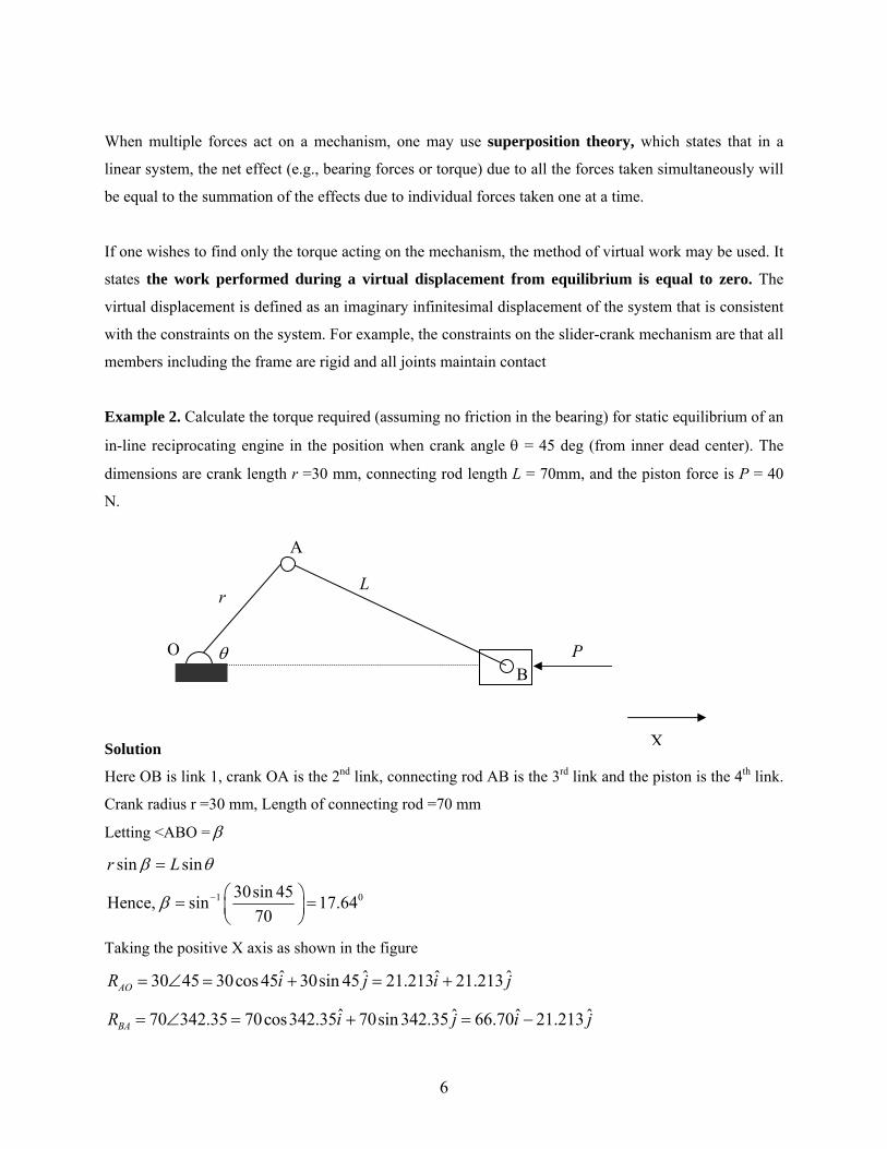
Example 2. Calculate the torque required (assuming no friction in the bearing) for static equilibrium of an
in-line reciprocating engine in the position when crank angle θ = 45 deg (from inner dead center). The
dimensions are crank length r =30 mm, connecting rod length L = 70mm, and the piston force is P = 40
N.
θB
A
O
Lr
P
Solution
Here OB is link 1, crank OA is the 2nd link, connecting rod AB is the 3rd link and th
Crank radius r =30 mm, Length of connecting rod =70 mm
Letting <ABO = β
1 0
sin sin30sin 45Hence, sin 17.64
70
r Lβ θ
β −
=
⎛ ⎞= =⎜ ⎟⎝ ⎠
Taking the positive X axis as shown in the figure
ˆ ˆ ˆ30 45 30cos 45 30sin 45 21.213 21.213AOR i j i= ∠ = + = + j
ˆi jˆ ˆ ˆ70 342.35 70cos342.35 70sin 342.35 66.70 21.213BAR i j= ∠ = + = −
6
X
e piston is the 4th link.
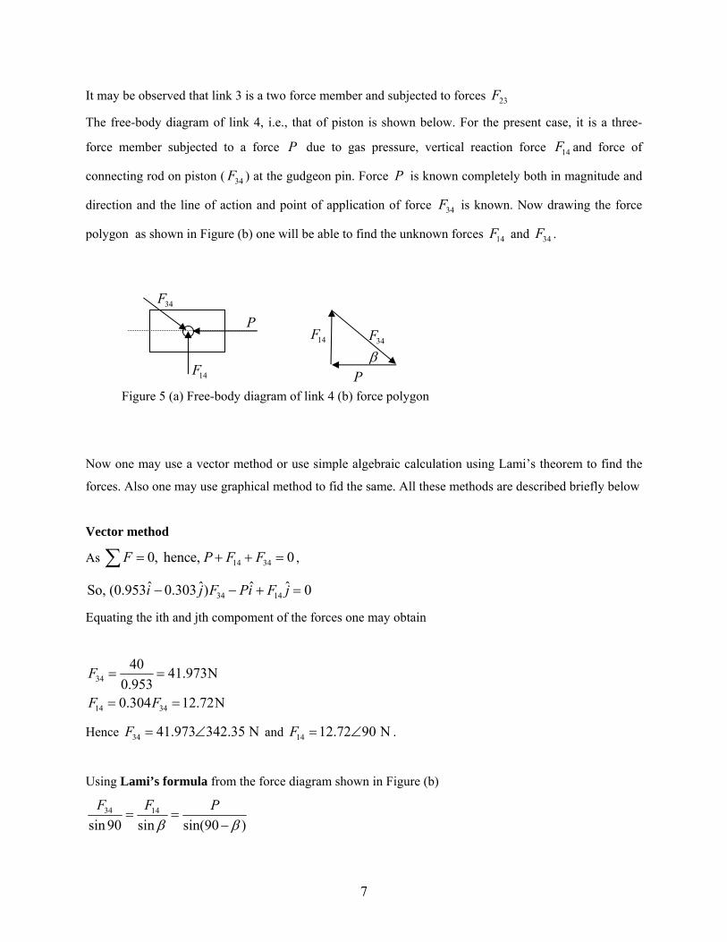
It may be observed that link 3 is a two force member and subjected to forces 23F
The free-body diagram of link 4, i.e., that of piston is shown below. For the present case, it is a three-
force member subjected to a force due to gas pressure, vertical reaction force and force of
connecting rod on piston ( ) at the gudgeon pin. Force is known completely both in magnitude and
direction and the line of action and point of application of force is known. Now drawing the force
polygon as shown in Figure (b) one will be able to find the unknown forces and .
P 14F
34F P
34F
14F 34F
P
14F
34F
β 14F 34F
P
Figure 5 (a) Free-body diagram of link 4 (b) force polygon
Now one may use a vector method or use simple algebraic calculation using Lami’s theorem to find the
forces. Also one may use graphical method to fid the same. All these methods are described briefly below
Vector method
As , 14 340, hence, 0F P F F= + +∑ =
=34 14ˆ ˆ ˆ ˆSo, (0.953 0.303 ) 0i j F Pi F j− − +
Equating the ith and jth compoment of the forces one may obtain
34
14 34
40 41.973N0.9530.304 12.72N
F
F F
= =
= =
Hence and 34 41.973 342.35 NF = ∠ 14 12.72 90 NF = ∠ .
Using Lami’s formula from the force diagram shown in Figure (b)
34 14
sin 90 sin sin(90 )F F P
β β= =
−
7
Hence
3440 41.974 N
sin(90 17.64)F = =
− and
8
1440sin(17.64) 12.72 N
sin(90 17.64)F = =
−.
23 43F F= −
23F
B
A
43F
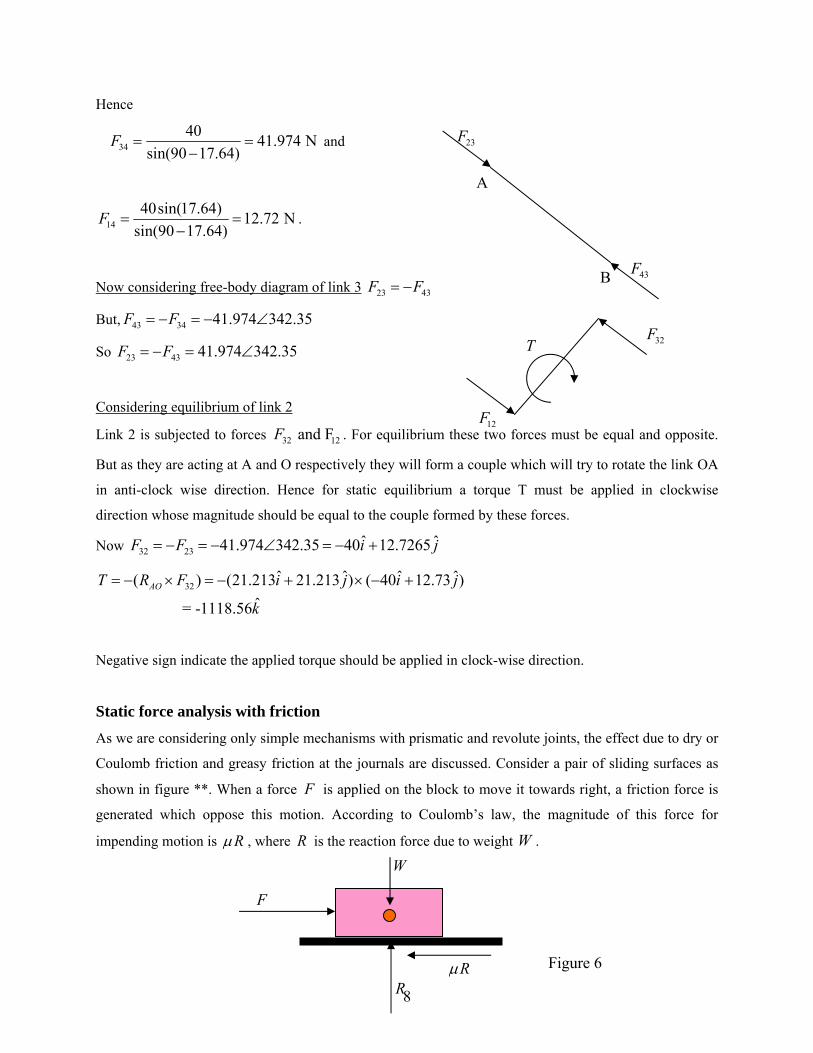
Now considering free-body diagram of link 3
But, 43 34 41.974 342.35F F= − = − ∠
So 23 43 41.974 342.35F F= − = ∠
Considering equilibrium of link 2
Link 2 is subjected to forces . For equilibrium these two forces must be equal and opposite.
But as they are acting at A and O respectively they will form a couple which will try to rotate the link OA
in anti-clock wise direction. Hence for static equilibrium a torque T must be applied in clockwise
direction whose magnitude should be equal to the couple formed by these forces.
32 12 and FF
32F
12F
T
Now 32 23ˆ ˆ41.974 342.35 40 12.7265F F i= − = − ∠ = − + j
j32ˆ ˆ ˆ( ) (21.213 21.213 ) ( 40 12.73 )
ˆ = -1118.56AOT R F i j i
k
= − × = − + × − +
Negative sign indicate the applied torque should be applied in clock-wise direction.
Static force analysis with friction
As we are considering only simple mechanisms with prismatic and revolute joints, the effect due to dry or
Coulomb friction and greasy friction at the journals are discussed. Consider a pair of sliding surfaces as
shown in figure **. When a force is applied on the block to move it towards right, a friction force is
generated which oppose this motion. According to Coulomb’s law, the magnitude of this force for
impending motion is
F
Rµ , where R is the reaction force due to weight . WW
F
Rµ R
Figure 6

Greasy friction at a journal
Generally greasy or boundary lubrication type friction force occurs in heavily loaded, slow running
bearings. Figure 7 (a) shows a journal inside a bearing during static condition. Here A is the contact point
and the weight of the journal W and the reaction force R act in the vertical directions as shown in the
figure. Now let us consider a torque T is applied to the journal in the clockwise direction. The friction
force will now oppose this motion and so the contact point between the bearing and the journal shifts to
point B as shown in figure (b). The resultant ( R ) of the normal reaction force ( nR ) and the friction force
( nRµ ) at B should be equal and opposite to the weight as the journal is under static equilibrium
condition. These two forces will form a couple in anticlockwise direction, which will oppose the applied
torque.
Let OC be the perpendicular distance between . If one draw a circle with radius OC and center
at O, the reaction force will be tangent to that circle. This circle is known as friction circle. Now to find
the radius of the friction circle, consider the triangle OBC. Here OC = OB sin
and W R
ϕ where ϕ is the angle
between the resultant and normal reaction force. Also the coefficient of friction tanµ ϕ= . Hence radius
of the friction circle = 2/( (1 )).fr rµ µ= + where r is the radius of the journal. For small value of µ ,
.fr rµ= Friction couple = 21
fWrr W Wrµ µ
µ=
+.
A
W
T
C r
nR R
B ϕ
R
W
n(a)
O O
Lubricant
Journal
Bearing
Rµ
(b)
Figure 7 (a) Journal in static condition (b) Journal when a torque is applied to start the motion.
9
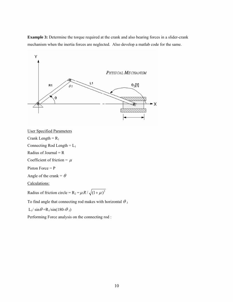
Example 3: Determine the torque required at the crank and also bearing forces in a slider-crank
mechanism when the inertia forces are neglected. Also develop a matlab code for the same.
User Specified Parameters
Crank Length = R1
Connecting Rod Length = L1
Radius of Journal = R
Coefficient of friction = µ
Piston Force = P
Angle of the crank = θ
Calculations:
Radius of friction circle = R2 = 2/ (1 )Rµ µ+
To find angle that connecting rod makes with horizontal θ 3
L1/ sinθ =R1/sin(180-θ 3)
Performing Force analysis on the connecting rod :
10

Free body diagram of crank:
Free Body diagram of slider:
Force of reaction by connecting rod on slider = F (Combination of forces F5 & F6)
Reaction force because of friction between ground and slider = Rxn (combination of Normal reaction NN
and friction f)
The following figures show the forces acting on the connecting rod, a combination of forces F5 and F6
11
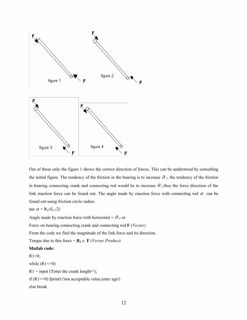
Out of these only the figure 1 shows the correct direction of forces. This can be understood by consulting
the initial figure. The tendency of the friction in the bearing is to increase ϑ 3 .the tendency of the friction
in bearing connecting crank and connecting rod would be to increase θ 2.thus the force direction of the
link reaction force can be found out. The angle made by reaction force with connecting rod α can be
found out using friction circle radius.
tan α = R2/(L1/2)
Angle made by reaction force with horizontal = θ 3-α
Force on bearing connecting crank and connecting rod F (Vector)
From the code we find the magnitude of the link force and its direction.
Torque due to this force = R1 x F (Vector Product)
Matlab code:
R1=0;
while (R1<=0)
R1 = input ('Enter the crank length=');
if (R1<=0) fprintf ('not acceptable value,enter agn')
else break
12

end
end;
L1=R1;
while (L1<=R1)
L1=input ('Enter the Connecting Rod Length=');
if (L1<=R1) fprintf ('not acceptable value,enter agn')
else break
end
end;
R=R1;
while (R>=(R1/10))
R=input ('enter the radius of journal=');
if (R>=(R1/10)) fprintf ('not acceptable value, enter agn')
else break
end
end;
C=1
while (C>=1)
C=input ('enter the coefficient of friction=');
if (C>=1) fprintf ('not acceptable value, enter agn')
else break
end
end;
P=input ('enter the piston force=');
Tht= input ('Enter the value of angle considered(degrees)=');
%R2=radius of journal bearing
Tht = Tht*pi/180;
R2= (C*R)/ sqrt (1+C^2)
A= atan ( (2*R2)/L1)
Tht3= asin ((R1/L1)*sin(Tht))
%Angle made with horizontal B
fprintf('the angle made by rxn force with horizontal')
B= 180*(Tht3-A)/pi
fprintf('the value of link rxn force=')
13
F=P/(cos(B)+sin(B)*C)
Rxn = (F*sin (Tht))/cos (atan(C));
fprintf('the value of torque=')
T= F*R1*sin (Tht + B)
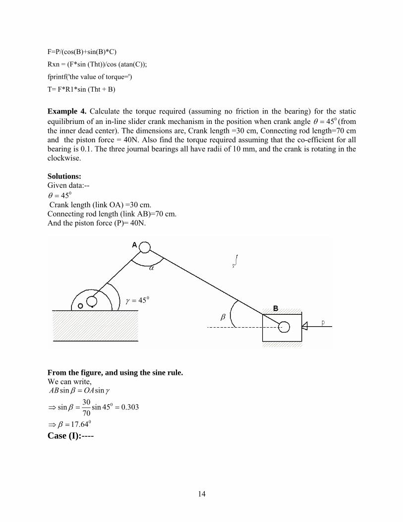
Example 4. Calculate the torque required (assuming no friction in the bearing) for the static equilibrium of an in-line slider crank mechanism in the position when crank angle (from the inner dead center). The dimensions are, Crank length =30 cm, Connecting rod length=70 cm and the piston force = 40N. Also find the torque required assuming that the co-efficient for all bearing is 0.1. The three journal bearings all have radii of 10 mm, and the crank is rotating in the clockwise.
045θ =
Solutions: Given data:--
045θ = Crank length (link OA) =30 cm. Connecting rod length (link AB)=70 cm. And the piston force (P)= 40N.
α
045=γ
β
From the figure, and using the sine rule. We can write,
0
0
sin sin30sin sin 45 0.30370
17.64
AB OAβ γ
β
β
=
⇒ = =
⇒ =
Case (I):----
14
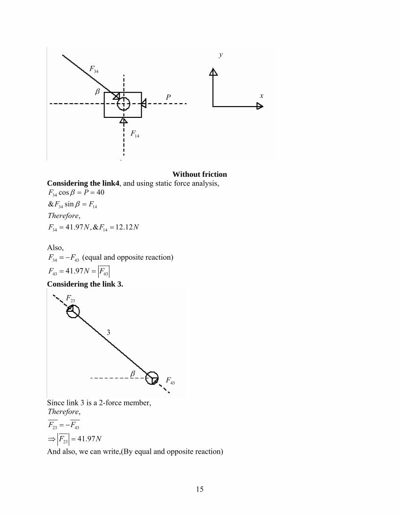
y
34F
β xP
14F
Without friction
Considering the link4, and using static force analysis, 34
34 14
34 14
cos 40& sin
,41.97 ,& 12.12
F PF F
ThereforeF N F N
ββ= ==
= =
Also, 34 43F F= − (equal and opposite reaction)
43 4341.97F N= = F
Considering the link 3.
23F
3
β43F
Since link 3 is a 2-force member,
23 43
23
,
41.97
Therefore
F F
F N
= −
⇒ =
And also, we can write,(By equal and opposite reaction)
15
32 23
32 41.97F F
F N= −
⇒ =
Considering link 2.
A
32Fα
β
045=γO
Now the torque due to reaction force is given by,
32
0 0ˆ ˆ ˆ0.03(cos 45 sin 45 ) 41.97( cos sin )ˆ1.112
T r F
T i j i
T kN m
jβ β
= ×
⇒ = + × − +
⇒ = − −
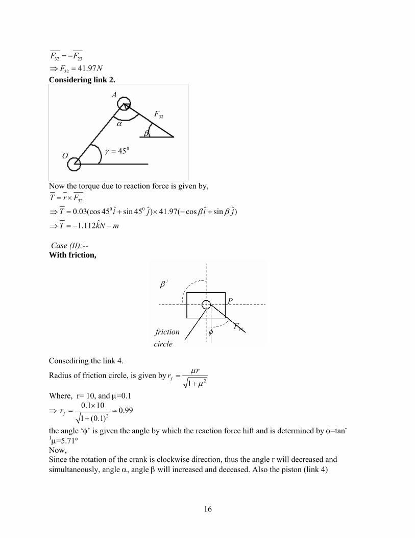
Case (II):-- With friction,
/β
P
14F
circlefriction φ
Consediring the link 4.
Radius of friction circle, is given by21
frr µµ
=+
Where, r= 10, and µ=0.1
⇒ 2
0.1 10 0.991 (0.1)
fr ×=
+
the angle ‘φ’ is given the angle by which the reaction force hift and is determined by φ=tan-
1µ=5.71° Now, Since the rotation of the crank is clockwise direction, thus the angle r will decreased and simultaneously, angle α, angle β will increased and deceased. Also the piston (link 4)
16
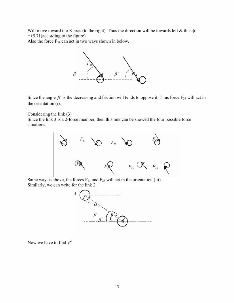
Will move toward the X-axis (to the right). Thus the direction will be towards left & thus φ =+5.71(according to the figure) Also the force F34 can act in two ways shown in below.
34F
34F/β /β
Since the angle β ′ is the decreasing and friction will tends to oppose it. Thus force F34 will act in the orientation (i). Considering the link (3) Since the link 3 is a 2-force member, then this link can be showed the four possible force situations.
23F 23F23F 23F
43F43F 43F 43F
Same way as above, the forces F43 and F23 will act in the orientation (iii). Similarly, we can write for the link 2.
A
D
β /θ/β B
Now we have to find β ′
17

1 1
0
0.9917.64 tan ( ) 17.64 tan ( ) 1635
16
frDB
0
β θ β
β β θ
β
− −
′ ′− =
′ ′⇒ = − = − = − =
′⇒ =
Now considering link .4. 34 14
34 14
34
14
cos sin&
sin cos,
42.8411.87
F P F
F FThereforeF NF N
β φ
β φ
′ = +
′ =
==
34 43 23 32 42.84F F F F= = = = N as in case (I) considering no friction. Considering link.2.
A
32Fr
12FO
Torque 32
0 0 0ˆ ˆ ˆ0.03(cos 45 sin 45 ) 42.84 ( cos16 sin16 )ˆ1.124
T r F
T i j i
T kN m
= ×
⇒ = + × × − +
⇒ = − −
0
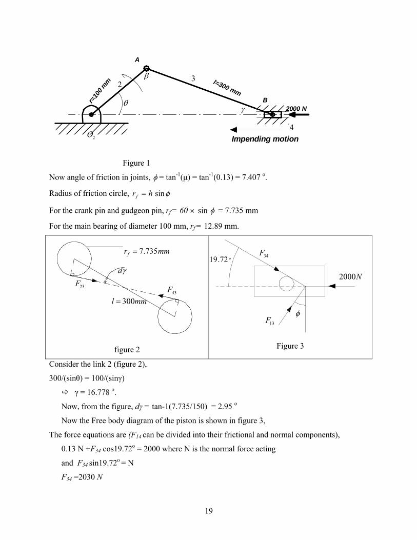
Example 5: Determine the driving torque available on the crank of a slider-crank mechanism, if
a force of 2000 N pointing towards the main bearing is applied horizontally to the piston. Length
of the crank and the connecting rod are 10 and 30 cm respectively. At the instant considered the
crank has rotated 60 degree (CCW) from the inner dead center. Take coefficient of friction
between all the pairing surfaces as 0.13. The diameter of the main bearing, crank pin and piston
pin are respectively 10, 6 and 6 cm. Also find the driving torque in the absence of friction using
virtual work principle.
Solution:
Considering the friction in all turning and sliding joints:
18
l=300 mmr=
100 m
m
A
B2000 N
Impending motion
θ
β
γ
32
42O
Figure 1
Now angle of friction in joints, φ = tan-1(µ) = tan-1(0.13) = 7.407 o.
Radius of friction circle, φsinhrf =
For the crank pin and gudgeon pin, rf = 60 × sin φ = 7.735 mm
For the main bearing of diameter 100 mm, rf = 12.89 mm.
figure 2
Figure 3
mmrf 735.7=34F
o72.19γd
N200023F
43Fmml 300=
φ13F
Consider the link 2 (figure 2),
300/(sinθ) = 100/(sinγ)
γ = 16.778 o.
Now, from the figure, dγ = tan-1(7.735/150) = 2.95 o
Now the Free body diagram of the piston is shown in figure 3,
The force equations are (F14 can be divided into their frictional and normal components),
0.13 N +F34 cos19.72o = 2000 where N is the normal force acting
and F34 sin19.72o = N
F34 =2030 N
19
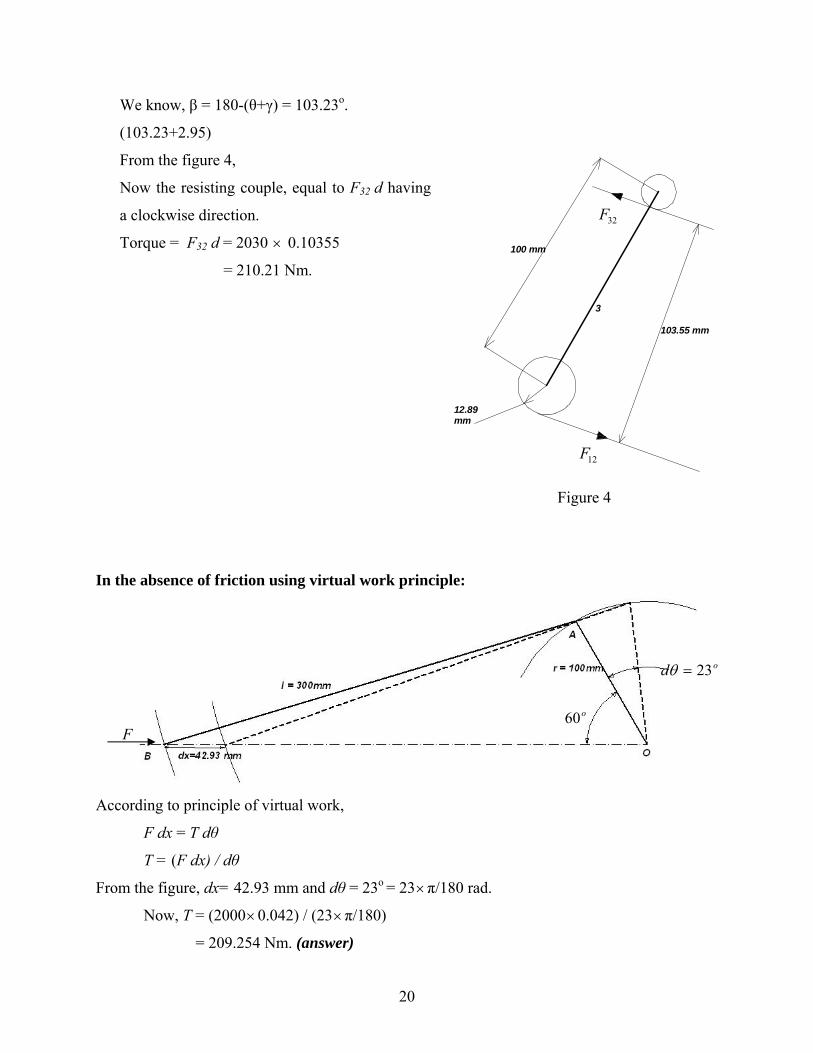
We know, β = 180-(θ+γ) = 103.23o.
(103.23+2.95)
From the figure 4,
Now the resisting couple, equal to F32 d having
a clockwise direction.
Torque = F32 d = 2030 × 0.10355
= 210.21 Nm.
103.55 mm
3
100 mm
12.89mm
Figure 4
32F
12F
In the absence of friction using virtual work principle:
od 23=θ
o60F
According to principle of virtual work,
F dx = T dθ
T = (F dx) / dθ
From the figure, dx= 42.93 mm and dθ = 23o = 23×π/180 rad.
Now, T = (2000×0.042) / (23×π/180)
= 209.254 Nm. (answer)
20
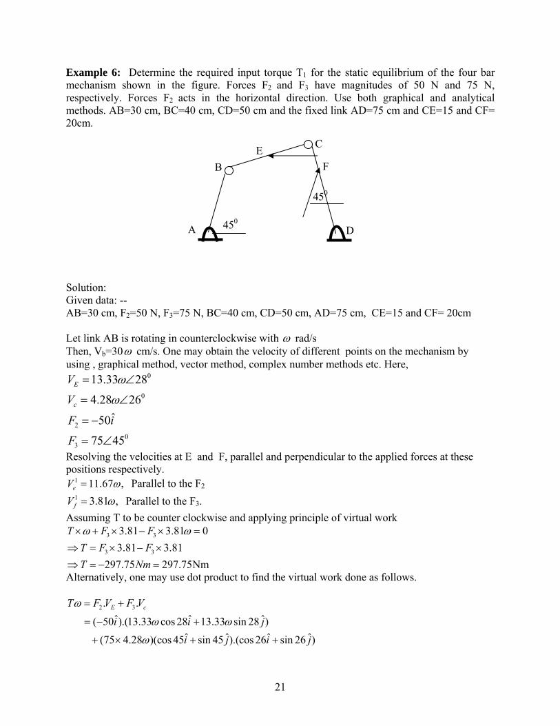
Example 6: Determine the required input torque T1 for the static equilibrium of the four bar mechanism shown in the figure. Forces F2 and F3 have magnitudes of 50 N and 75 N, respectively. Forces F2 acts in the horizontal direction. Use both graphical and analytical methods. AB=30 cm, BC=40 cm, CD=50 cm and the fixed link AD=75 cm and CE=15 and CF= 20cm.
D
C E
A
B F
450
450
Solution: Given data: -- AB=30 cm, F2=50 N, F3=75 N, BC=40 cm, CD=50 cm, AD=75 cm, CE=15 and CF= 20cm Let link AB is rotating in counterclockwise with ω rad/s Then, Vb=30ω cm/s. One may obtain the velocity of different points on the mechanism by using , graphical method, vector method, complex number methods etc. Here,
0
0
20
3
13.33 28
4.28 26ˆ50
75 45
E
c
V
V
F i
F
ω
ω
= ∠
= ∠
= −
= ∠
Resolving the velocities at E and F, parallel and perpendicular to the applied forces at these positions respectively.
1 11.67 ,eV ω= Parallel to the F2 1 3.81 ,fV ω= Parallel to the F3.
Assuming T to be counter clockwise and applying principle of virtual work 3 3
3 3
3.81 3.81 03.81 3.81
297.75 297.75Nm
T F FT F FT Nm
ω ω× + × − × =⇒ = × − ×⇒ = − =
Alternatively, one may use dot product to find the virtual work done as follows.
2 3. .ˆ ˆ ˆ ( 50 ).(13.33 cos 28 13.33 sin 28 )
ˆ ˆ ˆ (75 4.28 )(cos 45 sin 45 ).(cos 26 sin 26 )
E cT F V F V
i i j
i j i j
ω
ω ω
ω
= +
= − +
+ × + +
21
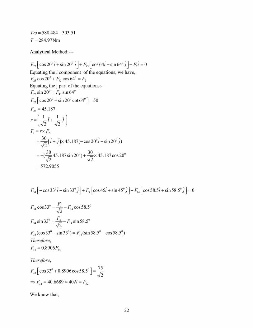
588.484 303.51284.97Nm
TTω = −=
Analytical Method:---
0 0 023 43 2
ˆ ˆ ˆ ˆ ˆcos 20 sin 20 cos 64 sin 64 0F i j F i j F i⎡ ⎤ ⎡ ⎤+ + − −⎣ ⎦ ⎣ ⎦ =
F
Equating the i component of the equations, we have,
0 023 43 2cos 20 cos 64F F+ =
Equating the j part of the equations:- 0 0
23 43sin 20 sin 64F F= 0 0 0
23
23
cos 20 sin 20 cot 64 50
45.187
F
F
⎡ ⎤+ =⎣ ⎦=
1 1ˆ ˆ2 2
r i⎛ ⎞= +⎜ ⎟⎝ ⎠
j
23aT r F= ×
( ) 0 0
0 0
30 ˆ ˆ ˆ ˆ45.187( cos 20 sin 20 )230 30( 45.187sin 20 ) 45.187cos 20
2 2572.9055
i j i j= + × − −
= − + ×
=
0 0 0 034 3 14
ˆ ˆ ˆ ˆ ˆ ˆcos33 sin 33 cos 45 sin 45 cos58.5 sin 58.5 0F i j F i j F i j⎡ ⎤ ⎡ ⎤ ⎡− − + + − +⎣ ⎦ ⎣ ⎦ ⎣ ⎤ =⎦
0 0334 14
0 0334 14
0 0 034 14
14 34
cos33 cos58.52
sin 33 sin 58.52
(cos33 sin 33 ) (sin 58.5 cos58.5 ),
0.8906
FF F
FF F
F FThereforeF F
= −
= −
− = −
=
0
0 034
34 32
,75cos33 0.8906cos58.5
240.6689 40
Therefore
F
F N F
⎡ ⎤+ =⎣ ⎦
⇒ = =
We know that,
22

0 032
0 0
30 ˆ ˆ( )2
,30 ˆ ˆ( ) 40.7 cos33 sin 33
230 40.7 sin 33 cos33 253.86
2
b
b
r i j
Therefore
T r F i j
T N
= +
⎡ ⎤= × = + × +⎣ ⎦
⎡ ⎤= × − = −⎣ ⎦
By superposition principle, ( ) 572.9055 253.68 319.04a bTotal T T T= + = − = , Ans.
Gear force Analysis The fundamental law of gearing states that in order to obtain a constant velocity ratio, the
common normal to the tooth profile at the point of contact should always pass through a fixed
point, called the pitch point. Thus the point of contact of the two gears has the same velocity.
Applying Newton’s third law, the force exerted by one gear to the other at the point of contact is
same in magnitude but opposite in direction. In this section the forces in spur and helical gears
are discussed.
Spur Gear In figure 8(a) shows the pitch circles of a pair of spur gears with center at a and b
and rotating with angular velocities 2ω and 3ω . The line of action and pressure angle φ are
clearly shown in this figure. In figure 8(b) the pair of constraint forces ( 23F d 32F cting at the
pitch point along the line of action are shown. Considering the freebody diagram of gear 2 as
shown in figure 8(c), the force is balanced by the reaction force acing at the bearing. As
these two forces are equal and opposite, they will form a couple. To overcome this reaction
couple, the prime mover (say motor) should provide a torque equal in magnitude but opposite in
direction, which is represented by in the figure.
an a)
32F 12F
a2T
23

(a) (c ) (b)
Figure 8 : Force analysis of Spur gear
One may resolve these forces in tangential and radial direction. Clearly, the tangential force is
responsible for rotating the gear.
Now let us derive an expression for the gear forces form the given power and speed of operation.
Let ‘ω’ be the speed of rotation (in rpm) of the gear with module ‘m’ and number of teeth ‘z’.
The value of the pressure angle(in degrees) is ‘Ф’ and the power (in KW) it transmits be ‘P’. The
diameter ‘D’ of the gear can be calculated as
D = m z (a)
and the torque ‘T’ transmitted by the gears is
660 10
2PT
πω×
= (b)
From Figure 8(c), we see that the force that is responsible for transmitting the torque ‘T’ is the
tangential component (Ft32 =Ft
23 =Ft). The radial component (Fr32 =Fr
23 =Fr) is the separating
force, which always acts towards the center of the gear. Thus we get
t tD 2T=T, or, F2 D
=F (c)
So, using equation (c) one may obtain the tangential force Ft from known value of D and T.
From Figure 8(c) the radial component can be obtained as
Fr = Ft tan Ф (d)
Hence the resultant force acting on the gear or on the bearing equals to 2 2t rF = (F F )+
Also one may note that t rF =Fcos and F Fsinφ φ=
24
Thus the net force ‘F’ can be easily calculated using the above expressions. This analysis of the
gear tooth force is based on certain assumptions which are as follows
1. As the point of contact moves, the value of the resultant force ‘F’ changes, which is
neglected in the above analysis.
2. It is assumed that only one pair of teeth take the entire load. At times there are two pairs
which simultaneously are in contact and share the load. This aspect is also neglected in
this case.
3. The analysis is valid under static conditions, when the gears are running at very low
velocities. In practice there are dynamic forces also due to the power transmission. The
effect of these dynamic forces are neglected in the analysis.
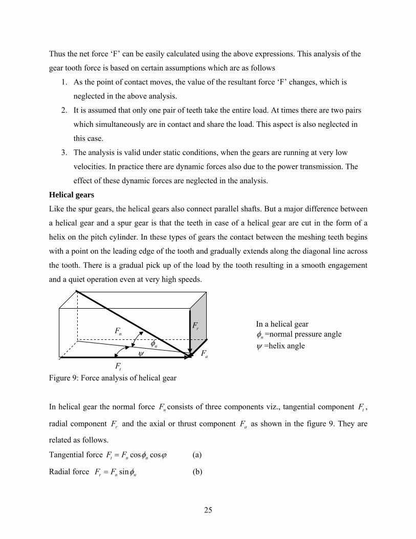
Helical gears
Like the spur gears, the helical gears also connect parallel shafts. But a major difference between
a helical gear and a spur gear is that the teeth in case of a helical gear are cut in the form of a
helix on the pitch cylinder. In these types of gears the contact between the meshing teeth begins
with a point on the leading edge of the tooth and gradually extends along the diagonal line across
the tooth. There is a gradual pick up of the load by the tooth resulting in a smooth engagement
and a quiet operation even at very high speeds.
nF
tF
rF
aF nφ
ψ
In a helical gear nφ =normal pressure angle
ψ =helix angle
Figure 9: Force analysis of helical gear
In helical gear the normal force consists of three components viz., tangential component ,
radial component and the axial or thrust component as shown in the figure 9. They are
related as follows.
nF tF
rF aF
Tangential force cos cost n nF F φ ϕ= (a)
Radial force sinr nF F nφ= (b)
25
Thrust or axial force = cos sin tana n n tF F Fφ ϕ ψ= = (c)
Let N be the speed of rotation in rpm of the gear with module m and number of teeth z, α is the
transverse pressure angle and ψ is the helix angle. Now the diameter D of the gear can be
determined from the relation
D = m z (d)
The angular velocity of the gear = 260
Nπω = (e)
The torque T transmitted by the gears can be calculated from the power P from the relation
P Tω= (f)
From Figure 9, we see that the force that is responsible for transmitting the torque ‘T’ is the
tangential component Ft. The radial component Fr is the separating force, which always acts
towards the center of the gear, and Fa is the axial or thrust component. The direction of this axial
component depends upon whether the gear is left or right handed, the direction of rotation and on
whether the driving or driven gear is under consideration. Thus we get
2tDT F= or 2
tTFD
= (g)
It may be recalled that the normal pressure angle nφ , helix angle ψ and transverse pressure angle
φ are related by
tancostan
nφψφ
= (h)
Once we have calculated the value of the normal pressure angle from (h), we can calculate the
tangential force from equations (f and g), axial or the thrust force using equation (c) and radial
component from expression (b). The resultant force on the helical gear can now be calculated
using the three components as
2 2 2( )n t rF F F F= + + a (i)
The following guidelines should be followed while calculating the axial or thrust component Fa
1. Select the driving gear from the pair.
2. Use right hand for right-handed helix and left hand for left handed helix.
3. Keep the fingers in the direction of rotation of the gear and the thumb will indicate the
direction of the thrust component of the driving gear.
26
4. The direction of the thrust component of the driven gear will be the opposite to that for
the driving gear.
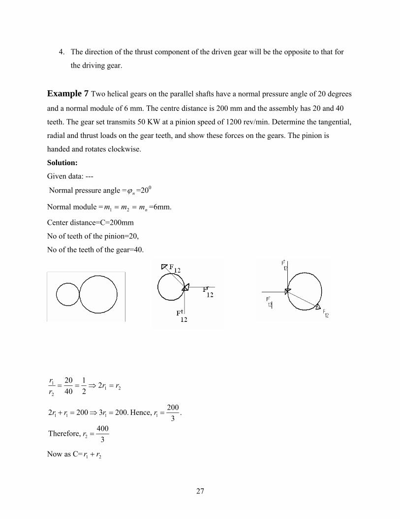
Example 7 Two helical gears on the parallel shafts have a normal pressure angle of 20 degrees
and a normal module of 6 mm. The centre distance is 200 mm and the assembly has 20 and 40
teeth. The gear set transmits 50 KW at a pinion speed of 1200 rev/min. Determine the tangential,
radial and thrust loads on the gear teeth, and show these forces on the gears. The pinion is
handed and rotates clockwise.
Solution:
Given data: ---
Normal pressure angle = nϕ =200
Normal module = =6mm. == 21 mm nm
Center distance=C=200mm
No of teeth of the pinion=20,
No of the teeth of the gear=40.
212
1 221
4020 rr
rr
=⇒==
1 1 1 1
2
2002 200 3 200. Hence, .3
400Therefore, 3
r r r r
r
+ = ⇒ = =
=
Now as C= 21 rr +
27

1 2 1 1 2 2 1 2
0
1 1 1( ) ( ) (2 2 2 cos
So, cos 25.8419
nmc d d m T m T T Tψ
ψ
= + = + = +
=
)
1 1 1
50kw,12002 ( ) 125.6rad/sec
6050 1000 398.089Nm
125.6
P
w
T w P T
π
=
= =
×= ⇒ = =
211
398.089 1000 5971.335(200 / 3)
T TF Nr
×= = =
We know that
12 21 21 12, Hence, 5971.335NT T T TF F F F= − = =
cos , cossin , sin
T Tn n n n n
r n n a n
F F F FF F F F
nφ φφ ψ
= == =
0
12 12
21 12
tan 5971.335 tan 25.8419 2892.04532N
,
a T
a a
F F
F F
ψ= = × =
= −
012 12 sin 5971.335 tan 20 2173.388Nr T
nF F φ= = × = Ans.
Summery
The following points are learned in this chapter
• Classification of forces: external and constraint forces • Determination of moments • Freebody diagram • Two and three force members • Static force analysis using graphical method • Static force analysis using analytical method (vector method) • Use of superposition theory for multiple external forces acting on a mechanism • Static force analysis with sliding and grease friction (concept of friction circle) • Application of virtual work principle for static force analysis.
28
Exercise Problems
1. Draw the constraint forces in all the six types of lower pairs, viz., (i) revolute or turning pair (ii) prismatic or sliding pair, (iii) cylindrical pair, (iv) screw or helical pair, (v) planar or flat pair, and (vi) globular or spherical pair.
2. Explain with neatly drawn free-body diagram the effect of friction in the bearings on the
torque required by the crankshaft in a slider-crank mechanism when the crank is rotating in (i) clock wise direction (ii) anti-clock wise direction.
3. Calculate the torque required for static equilibrium of an in-line slider crank mechanism
in the position when crank angle θ = 60 deg (from inner dead center). The dimensions are crank length r = 100 mm, connecting rod length L = 175 mm, and the piston force is P = 50 N. Assume crank to be rotating in anticlockwise direction. Use, graphical, analytical and virtual work principle to find the result.
4. Taking same data as in problem 3, also find the torque required assuming that the
coefficient of friction for all bearings is 0.1. The three journal bearings all have radii of 20 mm, and the crank is rotating in the clockwise direction.
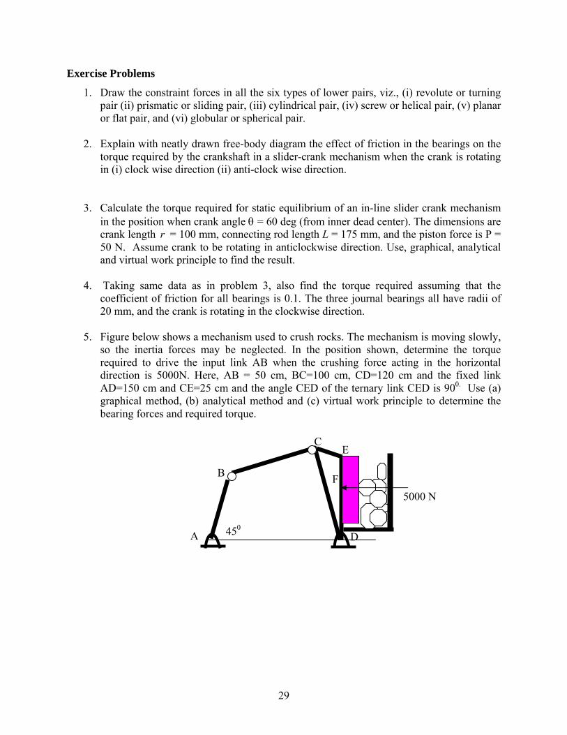
5. Figure below shows a mechanism used to crush rocks. The mechanism is moving slowly,
so the inertia forces may be neglected. In the position shown, determine the torque required to drive the input link AB when the crushing force acting in the horizontal direction is 5000N. Here, AB = 50 cm, BC=100 cm, CD=120 cm and the fixed link AD=150 cm and CE=25 cm and the angle CED of the ternary link CED is 900. Use (a) graphical method, (b) analytical method and (c) virtual work principle to determine the bearing forces and required torque.
5000 N
D A
B
E
450
C
F
29