Embed Size (px)
Citation preview

ET900
Intel ® CoreTM Duo/Solo 945GM COM Express (Type II) CPU Module
USER’S MANUAL Version 1.0

Acknowledgments
Award is a registered trademark of Award Software International, Inc. PS/2 is a trademark of International Business Machines Corporation. Intel and Celeron are registered trademarks of Intel Corporation. Microsoft Windows is a registered trademark of Microsoft Corporation. Winbond is a registered trademark of Winbond Electronics Corporation. All other product names or trademarks are properties of their respective owners. Attention: Before installing the CPU heat sink, remove the two protective sheaths as shown in the figure below.
Note:Remove the protectivesheath before installation.
ii ET900 User’s Manual
ET900 User’s Manual iii
Table of Contents
Introduction ....................................................... 1
Product Description ............................................................. 1 Checklist .............................................................................. 2 ET900 Specifications .......................................................... 3 Dimensions .......................................................................... 4 Installing the Processor ....................................................... 5 Installing the Memory ......................................................... 6 Connectors on ET900 .......................................................... 7
J2, J3: COM Express Type 2 Connectors ............................ 7
BIOS Setup ....................................................... 11
Drivers Installation ...................................... 35 Intel Chipset Software Installation Utility......................... 36 VGA Drivers Installation .................................................. 38 AC97 Codec Audio Driver Installation (IP400 carrier board only) .................................................................................. 40 Intel PRO LAN Drivers Installation .................................. 42 Marvell LAN Drivers Installation (IP400 carrier board only) ........................................................................................... 43
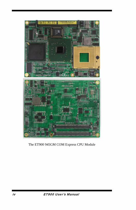
The ET900 945GM COM Express CPU Module
iv ET900 User’s Manual

INTRODUCTION
ET900 User’s Manual 1
Introduction Product Description The ET900 board incorporates the Mobile Intel® 945GM Express Chipset for Embedded Computing, consisting of the Intel® 945GM Graphic Memory Controller Hub (GMCH) and Intel® I/O Controller Hub 7-M (ICH7-M), an optimized integrated graphics solution with a 533MHz and 667MHz front-side bus. Dimensions of the board are 95mm x 125mm. The integrated powerful 3D graphics engine, based on Intel® Graphics Media Accelerator 950 (Intel® GMA 950) architecture, operates at core speeds of up to 400 MHz. It features a low-power design and is validated with the Intel® Core Duo/Solo on 65nm process. With DDR2 667MHz SO-DIMM socket on board, the board supports up to 2GB of DDR2 system memory. Intel® Graphics Media Accelerator 950 supports a unique intelligent memory management scheme called Dynamic Video Memory Technology (DVMT). DVMT handles diverse applications by providing the maximum (224MB) availability of system memory for general computer usage, while supplying additional graphics memory when a 3D-intensive application requests it. The Intel GMA 950 graphics architecture also takes advantage of the high-performance Intel processor. Intel GMA 950 graphics supports Dual Independent Display technology. The main features of the board are:
Supports COM ETX Type II Module pin-out definitions Supports Intel® CoreTM Duo/Solo processors Supports up to 533/667MHz FSB One DDR2 SDRAM SO-DIMM, Max. 2GB Intel® 945GM Express VGA for CRT / LVDS Intel® 945GM Integrated VGA; Supports CRT / LVDS Supports up to six x1 PCI-E, one x16 PCI-E, four PCI
INTRODUCTION
2 ET900 User’s Manual
Checklist Your ET900 package should include the items listed below.
• The ET900 CPU Module • This User’s Manual • 1 CD containing the following:
• Chipset Drivers • Flash Memory Utility
INTRODUCTION
ET900 User’s Manual 3
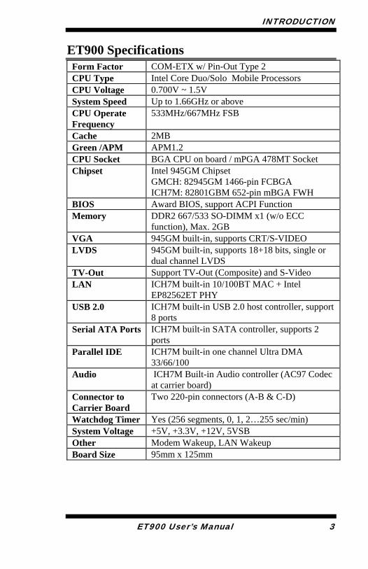
ET900 Specifications Form Factor COM-ETX w/ Pin-Out Type 2 CPU Type Intel Core Duo/Solo Mobile Processors CPU Voltage 0.700V ~ 1.5V System Speed Up to 1.66GHz or above CPU Operate Frequency
533MHz/667MHz FSB
Cache 2MB Green /APM APM1.2 CPU Socket BGA CPU on board / mPGA 478MT Socket Chipset Intel 945GM Chipset
GMCH: 82945GM 1466-pin FCBGA ICH7M: 82801GBM 652-pin mBGA FWH
BIOS Award BIOS, support ACPI Function Memory DDR2 667/533 SO-DIMM x1 (w/o ECC
function), Max. 2GB VGA 945GM built-in, supports CRT/S-VIDEO LVDS 945GM built-in, supports 18+18 bits, single or
dual channel LVDS TV-Out Support TV-Out (Composite) and S-Video LAN ICH7M built-in 10/100BT MAC + Intel
EP82562ET PHY USB 2.0 ICH7M built-in USB 2.0 host controller, support
8 ports Serial ATA Ports ICH7M built-in SATA controller, supports 2
ports Parallel IDE ICH7M built-in one channel Ultra DMA
33/66/100 Audio ICH7M Built-in Audio controller (AC97 Codec
at carrier board) Connector to Carrier Board
Two 220-pin connectors (A-B & C-D)
Watchdog Timer Yes (256 segments, 0, 1, 2…255 sec/min) System Voltage +5V, +3.3V, +12V, 5VSB Other Modem Wakeup, LAN Wakeup Board Size 95mm x 125mm
INTRODUCTION
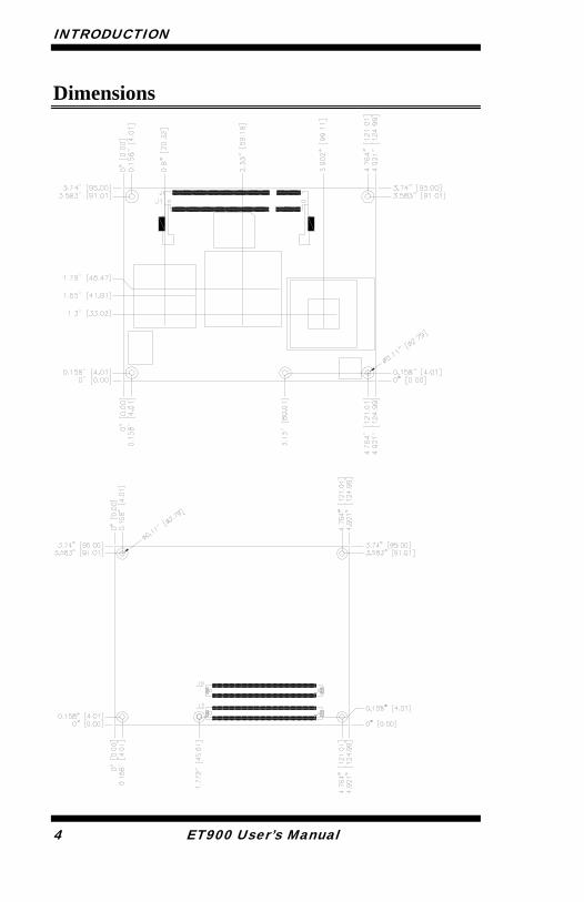
Dimensions
4 ET900 User’s Manual
INTRODUCTION
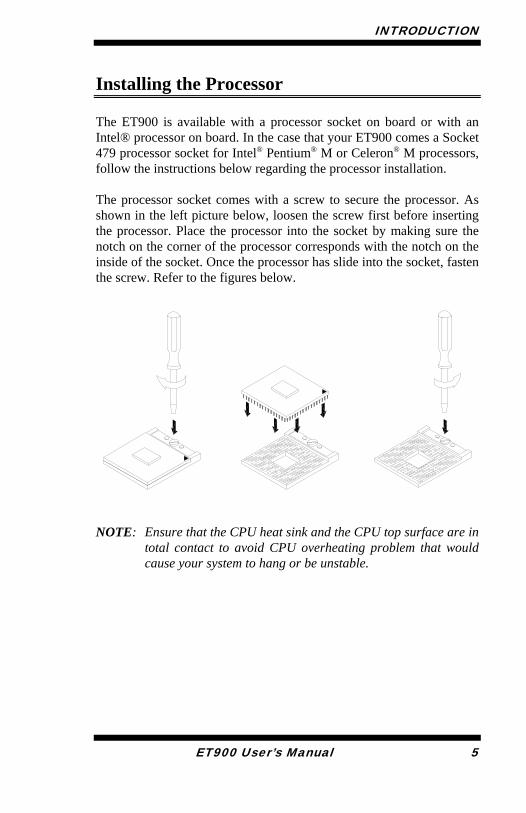
Installing the Processor The ET900 is available with a processor socket on board or with an Intel® processor on board. In the case that your ET900 comes a Socket 479 processor socket for Intel® Pentium® M or Celeron® M processors, follow the instructions below regarding the processor installation. The processor socket comes with a screw to secure the processor. As shown in the left picture below, loosen the screw first before inserting the processor. Place the processor into the socket by making sure the notch on the corner of the processor corresponds with the notch on the inside of the socket. Once the processor has slide into the socket, fasten the screw. Refer to the figures below.
NOTE: Ensure that the CPU heat sink and the CPU top surface are in
total contact to avoid CPU overheating problem that would cause your system to hang or be unstable.
ET900 User’s Manual 5
INTRODUCTION
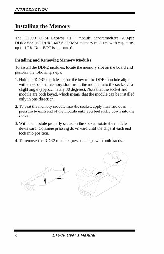
Installing the Memory The ET900 COM Express CPU module accommodates 200-pin DDR2-533 and DDR2-667 SODIMM memory modules with capacities up to 1GB. Non-ECC is supported.
Installing and Removing Memory Modules
To install the DDR2 modules, locate the memory slot on the board and perform the following steps:
1. Hold the DDR2 module so that the key of the DDR2 module align with those on the memory slot. Insert the module into the socket at a slight angle (approximately 30 degrees). Note that the socket and module are both keyed, which means that the module can be installed only in one direction.
2. To seat the memory module into the socket, apply firm and even pressure to each end of the module until you feel it slip down into the socket.
3. With the module properly seated in the socket, rotate the module downward. Continue pressing downward until the clips at each end lock into position.
4. To remove the DDR2 module, press the clips with both hands.
6 ET900 User’s Manual

INTRODUCTION
Connectors on ET900
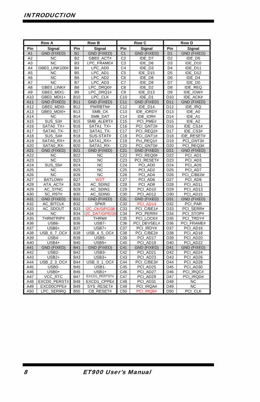
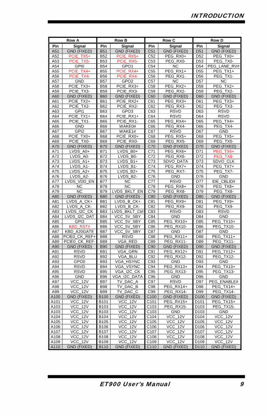
J2, J3: COM Express Type 2 Connectors The Type 2 connectors come in two 220-pin 0.5mm pitch receptacles. They include PCI, IDE, GBE and up to 22 general-purpose PCIE lanes (PCIE 0-5 and PCIE 16-31). For most Type 2 implementations, it is expected that PCIE lanes 16-31 are used for graphics. Hence they are designated PEG lanes 0-15 in the following table. Modules implementing Pin out Type 2, such as the ET900, uses the pin-out shown.
ET900 User’s Manual 7
INTRODUCTION
8 ET900 User’s Manual
Row A Row B Row C Row D
Pin Signal Pin Signal Pin Signal Pin Signal A1 GND (FIXED) B1 GND (FIXED) C1 GND (FIXED) D1 GND (FIXED)A2 NC B2 GBE0_ACT# C2 IDE_D7 D2 IDE_D5 A3 NC B3 LPC_FRAME# C3 IDE_D6 D3 IDE_D10 A4 GBE0_LINK100# B4 LPC_AD0 C4 IDE_D3 D4 IDE_D11 A5 NC B5 LPC_AD1 C5 IDE_D15 D5 IDE_D12 A6 NC B6 LPC_AD2 C6 IDE_D8 D6 IDE_D4 A7 NC B7 LPC_AD3 C7 IDE_D9 D7 IDE_D0 A8 GBE0_LINK# B8 LPC_DRQ0# C8 IDE_D2 D8 IDE_REQ A9 GBE0_MDI1- B9 LPC_DRQ1# C9 IDE_D13 D9 IDE_IOW#
A10 GBE0_MDI1+ B10 LPC_CLK C10 IDE_D1 D10 IDE_ACK# A11 GND (FIXED) B11 GND (FIXED) C11 GND (FIXED) D11 GND (FIXED)A12 GBE0_MDI0- B12 PWRBTN# C12 IDE_D14 D12 IDE_IRQ A13 GBE0_MDI0+ B13 SMB_CK C13 IDE_IORDY D13 IDE_A0 A14 NC B14 SMB_DAT C14 IDE_IOR# D14 IDE_A1 A15 SUS_S3# B15 SMB_ALERT# C15 PCI_PME# D15 IDE_A2 A16 SATA0_TX+ B16 SATA1_TX+ C16 PCI_GNT2# D16 IDE_CS1# A17 SATA0_TX- B17 SATA1_TX- C17 PCI_REQ2# D17 IDE_CS3# A18 SUS_S4# B18 SUS-STAT# C18 PCI_GNT1# D18 IDE_RESET#A19 SATA0_RX+ B19 SATA1_RX+ C19 PcI_REQ1# D19 PCI_GNT3# A20 SATA0_RX- B20 SATA1_RX- C20 PCI_GNT0# D20 PCI_REQ3# A21 GND (FI ED) X B21 GND (FIXED) C21 GND (FIXED) D21 GND (FIXED)A22 NC B22 NC C22 PCI_REQ0# D22 PCI_AD1 A23 NC B23 NC C23 PCI_RESE # T D23 PCI_AD3A24 SUS_S # 5 B24 NC C24 PCI_AD0 D24 PCI_AD5A25 NC B25 NC C25 PCI_AD2 D25 PCI_AD7A26 NC B26 NC C26 PCI_AD4 D26 PCI_C/BE0#A27 BATLOW# B27 WDT C27 PCI_AD6 D27 PCI_AD9A28 ATA_ACT# B28 AC_SDIN2 C28 PCI_AD8 D28 PCI_AD11A29 AC_SYNC B29 AC_SDIN1 C29 PCI_AD10 D29 PCI_AD13A30 SC_RST# B30 AC_SDIN0 C30 PCI_AD12 D30 PCI_AD15A31 GND (FIXED) B31 GND (FIXED) C31 GND (FIXED) D31 GND (FIXED)A32 AC_BITCLK B32 SPKR C32 PCI_AD14 D32 PCI_PARA33 AC_SDOUT B33 I2C_CK/GPIO38 C33 PCI_C/BE1# D33 PCI_SERR#A34 NC B34 I2C_DAT/GPIO39 C34 PCI_PERR# D34 PCI_STOP#A35 THRMTRIP# B35 THRM# C35 PCI_LOCK# D35 PCI_TRDY#A36 USB6- B36 USB7- C36 PCI_DEVSEL # D36 PCI_FRAME#A37 USB6+ B37 USB7+ C37 PCI_IRDY# D37 PCI_AD16A38 USB_6_7_OC# B38 USB_4_5_OC# C38 PCI_C/BE2 # D38 PCI_AD18A39 USB4- B39 USB5- C39 PCI_AD17 D39 PCI_AD20A40 USB4+ B40 USB5+ C40 PCI_AD19 D40 PCI_AD22A41 GND (FIXED) B41 GND (FIXED) C41 GND (FIXED) D41 GND (FIXED)A42 USB2- B42 USB3- C42 PCI_AD21 D42 PCI_AD24A43 USB2+ B43 USB3+ C43 PCI_AD23 D43 PCI_AD26A44 USB_2_3_OC# B44 USB_0_1_OC# C44 PCI_C/BE3 # D44 PCI_AD28A45 USB0- B45 USB1- C45 PCI_AD25 D45 PCI_AD30A46 USB0+ B46 USB1+ C46 PCI_AD27 D46 PCI_IRQC#A47 VCC_RTC B47 EXCD1_PERTST# C47 PCI_AD29 D47 PCI_IRQD#A48 EXCD0_PERST# B48 EXCD1_CPPE# C48 PCI_AD31 D48 NC A49 EXCD0CPPE# B49 SYS_RESET# C49 PCI_IRQA# D49 NC A50 LPC_SERIRQ B50 CB_RESET# C50 PCI_IRQB# D50 PCI_CLK
INTRODUCTION
ET900 User’s Manual 9
Row A Row B Row C Row D
Pin Signal Pin Signal Pin Signal Pin Signal A51 GND (FIXED) B51 GND (FIXED) C51 GND (FIXED) D51 GND (FIXED)A52 PCIE_TX5+ B52 PCIE_RX5+ C52 PEG_RX0+ D52 PEG_TX0+ A53 PCIE_TX5- B53 PCIE_RX5- C53 PEG_RX0- D53 PEG_TX0- A54 GPI0 B54 GPO1 C54 NC D54 PEG_LANE_RV#A55 PCIE_TX4+ B55 PCIE_RX4+ C55 PEG_RX1+ D55 PEG_TX1+ A56 PCIE_TX4- B56 PCIE_RX4- C56 PEG_RX1- D56 PEG_TX1- A57 GND B57 GPO2 C57 NC D57 NC A58 PCIE_TX3+ B58 PCIE_RX3+ C58 PEG_RX2+ D58 PEG_TX2+ A59 PCIE_TX3- B59 PCIE_RX3- C59 PEG_RX2- D59 PEG_TX2- A60 GND (FIXED) B60 GND (FIXED) C60 GND (FIXED) D60 GND (FIXED)A61 PCIE_TX2+ B61 PCIE_RX2+ C61 PEG_RX3+ D61 PEG_TX3+ A62 PCIE_TX2- B62 PCIE_RX2- C62 PEG_RX3- D62 PEG_TX3- A63 GPI1 B63 GPO3 C63 RSVD D63 RSVD A64 PCIE_TX1+ B64 PCIE_RX1+ C64 RSVD D64 RSVD A65 PCIE_TX1- B65 PCIE_RX1- C65 PEG_RX4+ D65 PEG_TX4+ A66 GND B66 WAKE0# C66 PEG_RX4- D66 PEG_TX4- A67 GPI2 B67 WAKE1# C67 RSVD D67 GND A68 PCIE_TX0+ B68 PCIE_RX0+ C68 PEG_RX5+ D68 PEG_TX5+ A69 PCIE_TX0- B69 PCIE_RX0- C69 PEG_RX5- D69 PEG_TX5- A70 GND (FIXED) B70 GND (FIXED) C70 GND (FIXED) D70 GND (FIXED)A71 LVDS_A0+ B71 LVDS_B0+ C71 PEG_RX6+ D71 PEG_TX6+ A72 LVDS_A0- B72 LVDS_B0- C72 PEG_RX6- D72 PEG_TX6- A73 LVDS_A1+ B73 LVDS_B1+ C73 SDVO_DATA D73 SDVO_CLK A74 LVDS_A1- B74 LVDS_B1- C74 PEG_RX7+ D74 PEG_TX7+ A75 LVDS_A2+ B75 LVDS_B2+ C75 PEG_RX7- D75 PEG_TX7- A76 LVDS_A2- B76 LVDS_B2- C76 GND D76 GND A77 LVDS_VDD_EN B77 NC C77 RSVD D77 IDE_CBLID# A78 NC B78 NC C78 PEG_RX8+ D78 PEG_TX8+ A79 NC B79 LVDS_BKLT_EN C79 PEG_RX8- D79 PEG_TX8- A80 GND (FIXED) B80 GND (FIXED) C80 GND (FIXED) D80 GND (FIXED)A81 LVDS_A_CK+ B81 LVDS_B_CK+ C81 PEG_RX9+ D81 PEG_TX9+ A82 LVDS_A_CK- B82 LVDS_B_CK- C82 PEG_RX9- D82 PEG_TX9- A83 LVDS_I2C_CK B83 LVDS_BKLT_Ctrl C83 RSVD D83 RSVD A84 LVDS_I2C_DAT B84 VCC_5V_SBY C84 GND D84 GND A85 GPI3 B85 VCC_5V_SBY C85 PEG_RX10+ D85 PEG_TX10+ A86 KBD_RST# B86 VCC_5V_SBY C86 PEG_RX10- D86 PEG_TX10- A87 KBD_A20GATE B87 VCC_5V_SBY C87 GND D87 GND A88 PCIE0_CK_REF+ B88 RSVD C88 PEG_RX11+ D88 PEG_TX11+ A89 PCIE0_CK_REF- B89 VGA_RED C89 PEG_RX11- D89 PEG_TX11- A90 GND (FIXED) B90 GND (FIXED) C90 GND (FIXED) D90 GND (FIXED)A91 RSVD B91 VGA_GRN C91 PEG_RX12+ D91 PEG_TX12+ A92 RSVD B92 VGA_BLU C92 PEG_RX12- D92 PEG_TX12- A93 GPO0 B93 VGA_HSYNC C93 GND D93 GND A94 RSVD B94 VGA_VSYNC C94 PEG_RX13+ D94 PEG_TX13+ A95 RSVD B95 VGA_I2C_CK C95 PEG_RX13- D95 PEG_TX13- A96 GND B96 VGA_I2C_DATA C96 GND D96 GND A97 VCC_12V B97 TV_DAC_A C97 RSVD D97 PEG_ENABLE#A98 VCC_12V B98 TV_DAC_B C98 PEG_RX14+ D98 PEG_TX14+ A99 VCC_12V B99 TV_DAC_C C99 PEG_RX14- D99 PEG_TX14-
A100 GND (FIXED) B100 GND (FIXED) C100 GND (FIXED) D100 GND (FIXED)A101 VCC_12V B101 VCC_12V C101 PEG_RX15+ D101 PEG_TX15+ A103 VCC_12V B103 VCC_12V C103 PEG_RX15- D103 PEG_TX15- A103 VCC_12V B103 VCC_12V C103 GND D103 GND A104 VCC_12V B104 VCC_12V C104 VCC_12V D104 VCC_12V A105 VCC_12V B105 VCC_12V C105 VCC_12V D105 VCC_12V A106 VCC_12V B106 VCC_12V C106 VCC_12V D106 VCC_12V A107 VCC_12V B107 VCC_12V C107 VCC_12V D107 VCC_12V A108 VCC_12V B108 VCC_12V C108 VCC_12V D108 VCC_12V A109 VCC_12V B109 VCC_12V C109 VCC_12V D109 VCC_12V A110 GND (FIXED) B110 GND (FIXED) C110 GND (FIXED) D110 GND (FIXED)

INTRODUCTION
10 ET900 User’s Manual
This page is intentionally left blank.
BIOS SETUP
ET900 User’s Manual 11
BIOS Setup This chapter describes the different settings available in the Award BIOS that comes with the board. The topics covered in this chapter are as follows:
BIOS Introduction ........................................................................ 12 BIOS Setup ................................................................................... 12 Standard CMOS Setup ................................................................. 14 Advanced BIOS Features ............................................................. 17 Advanced Chipset Features .......................................................... 20 Integrated Peripherals ................................................................... 23 Power Management Setup ............................................................ 27 PNP/PCI Configurations .............................................................. 30 PC Health Status ........................................................................... 31 Frequency/Voltage Control .......................................................... 32 Load Fail-Safe Defaults ................................................................ 33 Load Optimized Defaults ............................................................. 33 Set Supervisor/User Password ...................................................... 33 Save & Exit Setup ........................................................................ 33 Exit Without Saving ..................................................................... 33
BIOS SETUP
12 ET900 User’s Manual
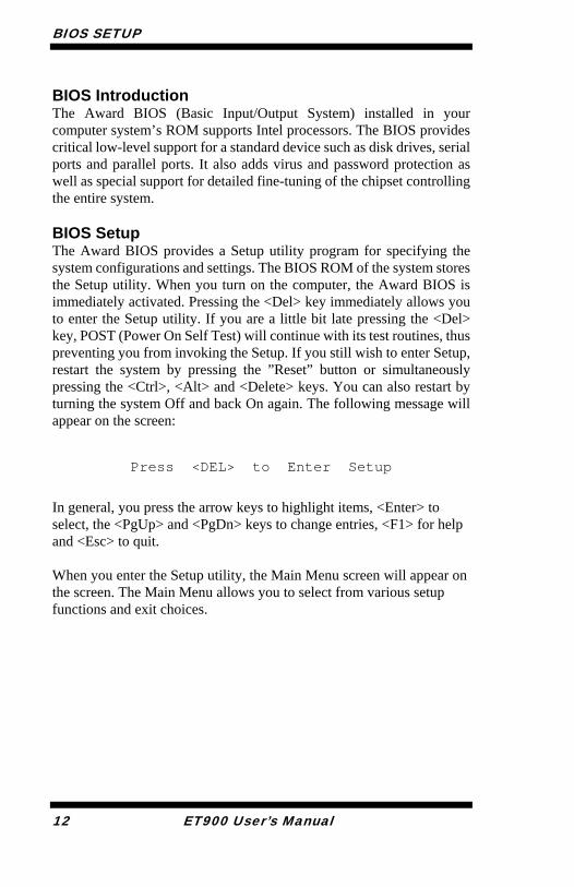
BIOS Introduction The Award BIOS (Basic Input/Output System) installed in your computer system’s ROM supports Intel processors. The BIOS provides critical low-level support for a standard device such as disk drives, serial ports and parallel ports. It also adds virus and password protection as well as special support for detailed fine-tuning of the chipset controlling the entire system. BIOS Setup The Award BIOS provides a Setup utility program for specifying the system configurations and settings. The BIOS ROM of the system stores the Setup utility. When you turn on the computer, the Award BIOS is immediately activated. Pressing the <Del> key immediately allows you to enter the Setup utility. If you are a little bit late pressing the <Del> key, POST (Power On Self Test) will continue with its test routines, thus preventing you from invoking the Setup. If you still wish to enter Setup, restart the system by pressing the ”Reset” button or simultaneously pressing the <Ctrl>, <Alt> and <Delete> keys. You can also restart by turning the system Off and back On again. The following message will appear on the screen:
Press <DEL> to Enter Setup
In general, you press the arrow keys to highlight items, <Enter> to select, the <PgUp> and <PgDn> keys to change entries, <F1> for help and <Esc> to quit. When you enter the Setup utility, the Main Menu screen will appear on the screen. The Main Menu allows you to select from various setup functions and exit choices.

BIOS SETUP
ET900 User’s Manual 13
Phoenix - AwardBIOS CMOS Setup Utility
Standard CMOS Features Frequency/Voltage Control Advanced BIOS Features Load Fail-Safe Defaults Advanced Chipset Features Load Optimized Defaults Integrated Peripherals Set Supervisor Password Power Management Setup Set User Password PnP/PCI Configurations Save & Exit Setup PC Health Status Exit Without Saving ESC : Quit : Select Item F10 : Save & Exit Setup
Time, Date, Hard Disk Type…
The section below the setup items of the Main Menu displays the control keys for this menu. At the bottom of the Main Menu just below the control keys section, there is another section, which displays information on the currently highlighted item in the list. Note: If the system cannot boot after making and saving system
changes with Setup, the Award BIOS supports an override to the CMOS settings that resets your system to its default.
Warning: It is strongly recommended that you avoid making any
changes to the chipset defaults. These defaults have been carefully chosen by both Award and your system manufacturer to provide the absolute maximum performance and reliability. Changing the defaults could cause the system to become unstable and crash in some cases.
BIOS SETUP
14 ET900 User’s Manual
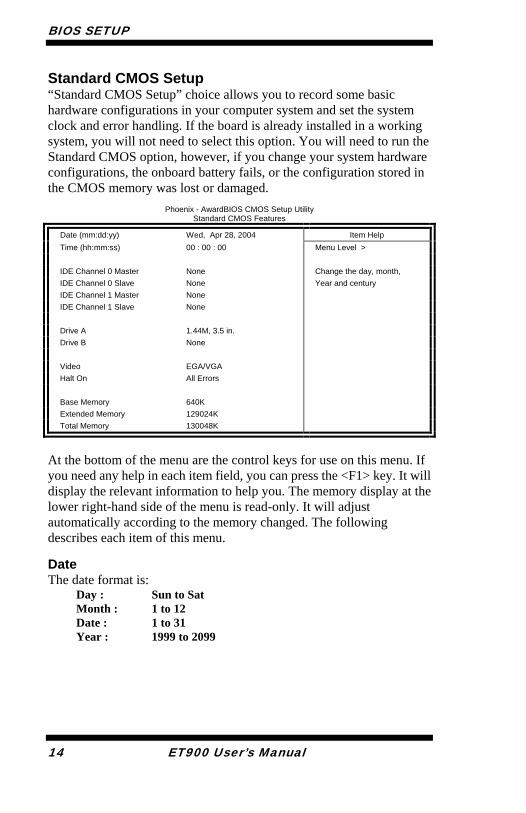
Standard CMOS Setup “Standard CMOS Setup” choice allows you to record some basic hardware configurations in your computer system and set the system clock and error handling. If the board is already installed in a working system, you will not need to select this option. You will need to run the Standard CMOS option, however, if you change your system hardware configurations, the onboard battery fails, or the configuration stored in the CMOS memory was lost or damaged.
Phoenix - AwardBIOS CMOS Setup Utility Standard CMOS Features
Date (mm:dd:yy) Wed, Apr 28, 2004 Item Help Time (hh:mm:ss) 00 : 00 : 00 Menu Level > IDE Channel 0 Master None Change the day, month,
Year and century IDE Channel 0 Slave None IDE Channel 1 Master None IDE Channel 1 Slave None Drive A 1.44M, 3.5 in. Drive B None Video EGA/VGA Halt On All Errors Base Memory 640K Extended Memory 129024K Total Memory 130048K
At the bottom of the menu are the control keys for use on this menu. If you need any help in each item field, you can press the <F1> key. It will display the relevant information to help you. The memory display at the lower right-hand side of the menu is read-only. It will adjust automatically according to the memory changed. The following describes each item of this menu. Date The date format is:
Day : Sun to Sat Month : 1 to 12 Date : 1 to 31 Year : 1999 to 2099
BIOS SETUP
ET900 User’s Manual 15
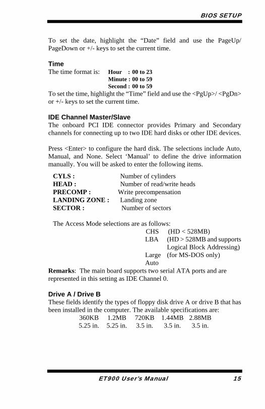
To set the date, highlight the “Date” field and use the PageUp/ PageDown or +/- keys to set the current time. Time The time format is: Hour : 00 to 23
Minute : 00 to 59 Second : 00 to 59
To set the time, highlight the “Time” field and use the <PgUp>/ <PgDn> or +/- keys to set the current time. IDE Channel Master/Slave The onboard PCI IDE connector provides Primary and Secondary channels for connecting up to two IDE hard disks or other IDE devices. Press <Enter> to configure the hard disk. The selections include Auto, Manual, and None. Select ‘Manual’ to define the drive information manually. You will be asked to enter the following items.
CYLS : Number of cylinders HEAD : Number of read/write heads PRECOMP : Write precompensation LANDING ZONE : Landing zone SECTOR : Number of sectors The Access Mode selections are as follows: CHS (HD < 528MB)
LBA (HD > 528MB and supports Logical Block Addressing)
Large (for MS-DOS only) Auto
Remarks: The main board supports two serial ATA ports and are represented in this setting as IDE Channel 0.
Drive A / Drive B These fields identify the types of floppy disk drive A or drive B that has been installed in the computer. The available specifications are: 360KB
5.25 in.1.2MB5.25 in.
720KB 3.5 in.
1.44MB3.5 in.
2.88MB3.5 in.

BIOS SETUP
16 ET900 User’s Manual
Video This field selects the type of video display card installed in your system. You can choose the following video display cards: EGA/VGA For EGA, VGA, SEGA, SVGA or PGA monitor adapters. (default) CGA 40 Power up in 40 column mode. CGA 80 Power up in 80 column mode. MONO For Hercules or MDA adapters. Halt On This field determines whether or not the system will halt if an error is detected during power up. No errors The system boot will not be halted for any error
that may be detected. All errors Whenever the BIOS detects a non-fatal error,
the system will stop and you will be prompted.All, But Keyboard The system boot will not be halted for a
keyboard error; it will stop for all other errorsAll, But Diskette The system boot will not be halted for a disk
error; it will stop for all other errors. All, But Disk/Key The system boot will not be halted for a key-
board or disk error; it will stop for all others.
BIOS SETUP
ET900 User’s Manual 17
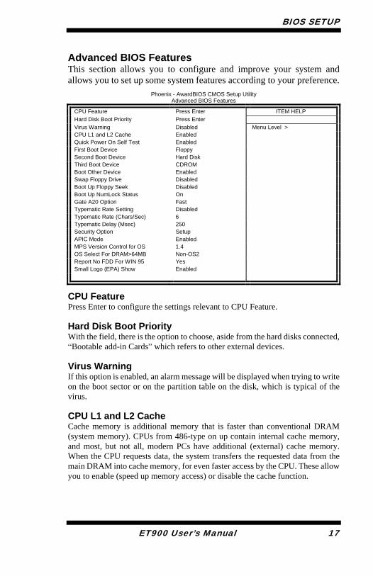
Advanced BIOS Features This section allows you to configure and improve your system and allows you to set up some system features according to your preference.
Phoenix - AwardBIOS CMOS Setup Utility Advanced BIOS Features
CPU Feature Press Enter ITEM HELP Hard Disk Boot Priority Press Enter Virus Warning Disabled Menu Level > CPU L1 and L2 Cache Enabled Quick Power On Self Test Enabled First Boot Device Floppy Second Boot Device Hard Disk Third Boot Device CDROM Boot Other Device Enabled Swap Floppy Drive Disabled Boot Up Floppy Seek Disabled Boot Up NumLock Status On Gate A20 Option Fast Typematic Rate Setting Disabled Typematic Rate (Chars/Sec) 6 Typematic Delay (Msec) 250 Security Option Setup APIC Mode Enabled MPS Version Control for OS 1.4 OS Select For DRAM>64MB Non-OS2 Report No FDD For WIN 95 Yes Small Logo (EPA) Show Enabled
CPU Feature Press Enter to configure the settings relevant to CPU Feature. Hard Disk Boot Priority With the field, there is the option to choose, aside from the hard disks connected, “Bootable add-in Cards” which refers to other external devices. Virus Warning If this option is enabled, an alarm message will be displayed when trying to write on the boot sector or on the partition table on the disk, which is typical of the virus. CPU L1 and L2 Cache Cache memory is additional memory that is faster than conventional DRAM (system memory). CPUs from 486-type on up contain internal cache memory, and most, but not all, modern PCs have additional (external) cache memory. When the CPU requests data, the system transfers the requested data from the main DRAM into cache memory, for even faster access by the CPU. These allow you to enable (speed up memory access) or disable the cache function.
BIOS SETUP
18 ET900 User’s Manual
Quick Power On Self Test When enabled, this field speeds up the Power On Self Test (POST) after the system is turned on. If it is set to Enabled, BIOS will skip some items. First/Second/Third Boot Device These fields determine the drive that the system searches first for an operating system. The options available include Floppy, LS120, Hard Disk, CDROM, ZIP100, USB-Floppy, USB-ZIP, USB-CDROM, LAN and Disable. Boot Other Device These fields allow the system to search for an OS from other devices other than the ones selected in the First/Second/Third Boot Device. Swap Floppy Drive This item allows you to determine whether or not to enable Swap Floppy Drive. When enabled, the BIOS swaps floppy drive assignments so that Drive A becomes Drive B, and Drive B becomes Drive A. By default, this field is set to Disabled. Boot Up Floppy Seek This feature controls whether the BIOS checks for a floppy drive while booting up. If it cannot detect one (either due to improper configuration or its absence), it will flash an error message. Boot Up NumLock Status This allows you to activate the NumLock function after you power up the system. Gate A20 Option This field allows you to select how Gate A20 is worked. Gate A20 is a device used to address memory above 1 MB. Typematic Rate Setting When disabled, continually holding down a key on your keyboard will generate only one instance. When enabled, you can set the two typematic controls listed next. By default, this field is set to Disabled. Typematic Rate (Chars/Sec) When the typematic rate is enabled, the system registers repeated keystrokes speeds. Settings are from 6 to 30 characters per second.
BIOS SETUP
ET900 User’s Manual 19
Typematic Delay (Msec) When the typematic rate is enabled, this item allows you to set the time interval for displaying the first and second characters. By default, this item is set to 250msec. Security Option This field allows you to limit access to the System and Setup. The default value is Setup. When you select System, the system prompts for the User Password every time you boot up. When you select Setup, the system always boots up and prompts for the Supervisor Password only when the Setup utility is called up. APIC Mode APIC stands for Advanced Programmable Interrupt Controller. The default setting is Enabled. MPS Version Control for OS This option is specifies the MPS (Multiprocessor Specification) version for your operating system. MPS version 1.4 added extended configuration tables to improve support for multiple PCI bus configurations and improve future expandability. The default setting is 1.4.
OS Select for DRAM > 64MB This option allows the system to access greater than 64MB of DRAM memory when used with OS/2 that depends on certain BIOS calls to access memory. The default setting is Non-OS/2. Report No FDD For WIN 95 If you are using Windows 95/98 without a floppy disk drive, select Enabled to release IRQ6. This is required to pass Windows 95/98's SCT test. You should also disable the Onboard FDC Controller in the Integrated Peripherals screen when there's no floppy drive in the system. If you set this feature to Disabled, the BIOS will not report the missing floppy drive to Win95/98. Small Logo (EPA) Show The EPA logo appears at the right side of the monitor screen when the system is boot up. The default setting is Enabled.
BIOS SETUP
20 ET900 User’s Manual
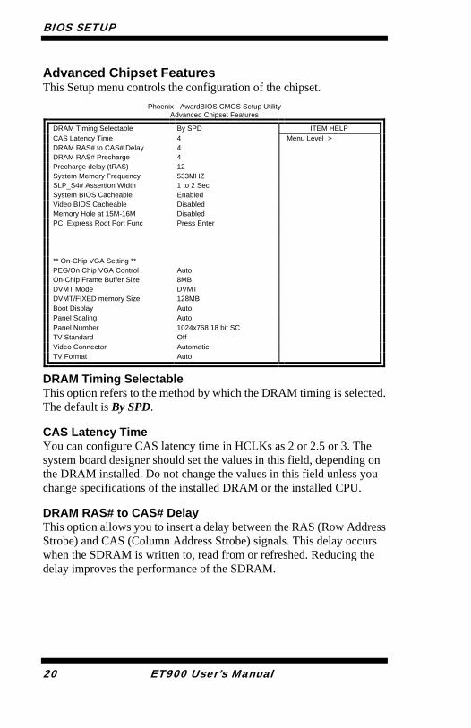
Advanced Chipset Features This Setup menu controls the configuration of the chipset.
Phoenix - AwardBIOS CMOS Setup Utility Advanced Chipset Features
DRAM Timing Selectable By SPD ITEM HELP CAS Latency Time 4 Menu Level > DRAM RAS# to CAS# Delay 4 DRAM RAS# Precharge 4 Precharge delay (tRAS) 12 System Memory Frequency 533MHZ SLP_S4# Assertion Width 1 to 2 Sec System BIOS Cacheable Enabled Video BIOS Cacheable Disabled Memory Hole at 15M-16M Disabled PCI Express Root Port Func Press Enter
** On-Chip VGA Setting ** PEG/On Chip VGA Control Auto On-Chip Frame Buffer Size 8MB DVMT Mode DVMT DVMT/FIXED memory Size 128MB Boot Display Auto Panel Scaling Auto Panel Number 1024x768 18 bit SC TV Standard Off Video Connector Automatic TV Format Auto
DRAM Timing Selectable This option refers to the method by which the DRAM timing is selected. The default is By SPD. CAS Latency Time You can configure CAS latency time in HCLKs as 2 or 2.5 or 3. The system board designer should set the values in this field, depending on the DRAM installed. Do not change the values in this field unless you change specifications of the installed DRAM or the installed CPU. DRAM RAS# to CAS# Delay This option allows you to insert a delay between the RAS (Row Address Strobe) and CAS (Column Address Strobe) signals. This delay occurs when the SDRAM is written to, read from or refreshed. Reducing the delay improves the performance of the SDRAM.
BIOS SETUP
ET900 User’s Manual 21
DRAM RAS# Precharge This option sets the number of cycles required for the RAS to accumulate its charge before the SDRAM refreshes. The default setting for the Active to Precharge Delay is 4. Precharge Delay (tRAS) The default setting for the Precharge Delay is 12. System Memory Frequency The default setting is 533MHz.
SLP_S4# Assertion Width The default setting is 1 to 2 Sec.
System BIOS Cacheable The setting of Enabled allows caching of the system BIOS ROM at F000h-FFFFFh, resulting in better system performance. However, if any program writes to this memory area, a system error may result. Video BIOS Cacheable The Setting Enabled allows caching of the video BIOS ROM at C0000h-F7FFFh, resulting in better video performance. However, if any program writes to this memory area, a system error may result. Memory Hole At 15M-16M In order to improve performance, certain space in memory can be reserved for ISA cards. This memory must be mapped into the memory space below 16 MB. The choices are Enabled and Disabled.
On-Chip VGA Setting The fields under the On-Chip VGA Setting and their default settings are:
PEG/On Chip VGA Control: Auto On-Chip Frame Buffer Size: 8MB DVMT Mode: DVTM DVMT/Fixed Memory Size: 128MB Boot Display: Auto Panel Scaling: Auto Panel Number: 1024x768 18 bit SC TV Standard: Off Video Connector: Automatic TV Format: Auto
BIOS SETUP
22 ET900 User’s Manual
Panel Scaling The default setting is Auto. The options available include On and Off. Panel Number These fields allow you to select the LCD Panel type. The default values for these ports are:
640x480 18bit SC 800x480 18bit SC 800x600 18bit SC 1024x768 18bit SC 1280x1024 18bit DC1280x768 18bit SC 1400x1050 18bit DC1600x1200 18bit DC

BIOS SETUP
ET900 User’s Manual 23
Integrated Peripherals This section sets configurations for your hard disk and other integrated peripherals. The first screen shows three main items for user to select. Once an item selected, a submenu appears. Details follow.
Phoenix - AwardBIOS CMOS Setup Utility Integrated Peripherals
OnChip IDE Device Press Enter ITEM HELP Onboard Device Press Enter Menu Level > SuperIO Device Press Enter
Phoenix - AwardBIOS CMOS Setup Utility
OnChip IDE Device
IDE HDD Block Mode Enabled ITEM HELP On-chip Primary PCI IDE Enabled IDE Primary Master PIO Auto Menu Level > IDE Primary Slave PIO Auto IDE Primary Master UDMA Auto IDE Primary Slave UDMA Auto On-Chip Secondary PCI IDE Enabled IDE Secondary Master PIO Auto IDE Secondary Slave PIO Auto IDE Secondary Master UDMA Auto IDE Secondary Slave UDMA Auto *** On-Chip Serial ATA Setting *** On-Chip Serial ATA Auto PATA IDE Mode Secondary SATA port P0, P2 is Primary
Phoenix - AwardBIOS CMOS Setup Utility
Onboard Device
USB Controller Enabled ITEM HELP USB 2.0 Controller Enabled Menu Level > USB Keyboard Support Disabled AC97 Audio Select Auto
BIOS SETUP
24 ET900 User’s Manual
Phoenix - AwardBIOS CMOS Setup Utility
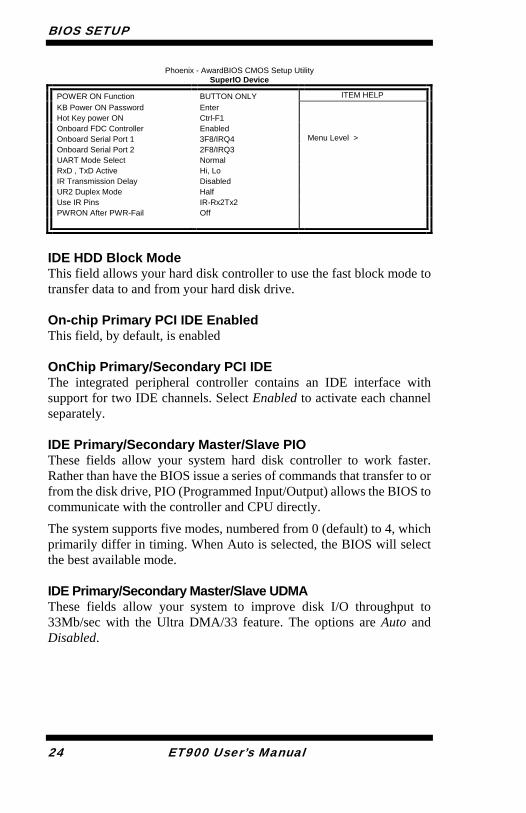
SuperIO Device
POWER ON Function BUTTON ONLY ITEM HELP KB Power ON Password Enter Hot Key power ON Ctrl-F1 Onboard FDC Controller Enabled Onboard Serial Port 1 3F8/IRQ4 Menu Level > Onboard Serial Port 2 2F8/IRQ3 UART Mode Select Normal RxD , TxD Active Hi, Lo IR Transmission Delay Disabled UR2 Duplex Mode Half Use IR Pins IR-Rx2Tx2 PWRON After PWR-Fail Off
IDE HDD Block Mode This field allows your hard disk controller to use the fast block mode to transfer data to and from your hard disk drive. On-chip Primary PCI IDE Enabled This field, by default, is enabled OnChip Primary/Secondary PCI IDE The integrated peripheral controller contains an IDE interface with support for two IDE channels. Select Enabled to activate each channel separately. IDE Primary/Secondary Master/Slave PIO These fields allow your system hard disk controller to work faster. Rather than have the BIOS issue a series of commands that transfer to or from the disk drive, PIO (Programmed Input/Output) allows the BIOS to communicate with the controller and CPU directly.
The system supports five modes, numbered from 0 (default) to 4, which primarily differ in timing. When Auto is selected, the BIOS will select the best available mode. IDE Primary/Secondary Master/Slave UDMA These fields allow your system to improve disk I/O throughput to 33Mb/sec with the Ultra DMA/33 feature. The options are Auto and Disabled.
BIOS SETUP
ET900 User’s Manual 25
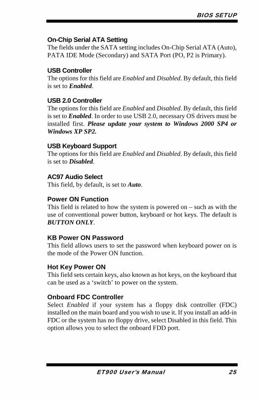
On-Chip Serial ATA Setting The fields under the SATA setting includes On-Chip Serial ATA (Auto), PATA IDE Mode (Secondary) and SATA Port (PO, P2 is Primary). USB Controller The options for this field are Enabled and Disabled. By default, this field is set to Enabled. USB 2.0 Controller The options for this field are Enabled and Disabled. By default, this field is set to Enabled. In order to use USB 2.0, necessary OS drivers must be installed first. Please update your system to Windows 2000 SP4 or Windows XP SP2. USB Keyboard Support The options for this field are Enabled and Disabled. By default, this field is set to Disabled. AC97 Audio Select This field, by default, is set to Auto. Power ON Function This field is related to how the system is powered on – such as with the use of conventional power button, keyboard or hot keys. The default is BUTTON ONLY.
KB Power ON Password This field allows users to set the password when keyboard power on is the mode of the Power ON function. Hot Key Power ON This field sets certain keys, also known as hot keys, on the keyboard that can be used as a ‘switch’ to power on the system. Onboard FDC Controller Select Enabled if your system has a floppy disk controller (FDC) installed on the main board and you wish to use it. If you install an add-in FDC or the system has no floppy drive, select Disabled in this field. This option allows you to select the onboard FDD port.
BIOS SETUP
26 ET900 User’s Manual
Onboard Serial Port These fields allow you to select the onboard serial ports and their addresses. The default values for these ports are: Serial Port 1 3F8/IRQ4 Serial Port 2 2F8/IRQ3 UART Mode Select This field determines the UART 2 mode in your computer. The default value is Normal. Other options include IrDA and ASKIR. PWRON After PWR-Fail This field sets the system power status whether on or off when power returns to the system from a power failure situation.
BIOS SETUP
ET900 User’s Manual 27
Power Management Setup
Phoenix - AwardBIOS CMOS Setup Utility Power Management Setup
ACPI Function Enabled ITEM HELP
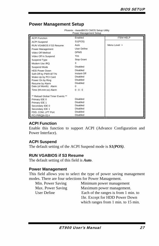
ACPI Suspend S1(POS) RUN VGABIOS if S3 Resume Auto Menu Level > Power Management User Define Video Off Method DPMS Video Off In Suspend Yes Suspend Type Stop Grant Modem Use IRQ 3 Suspend Mode Disabled HDD Power Down Disabled Soft-Off by PWR-BTTN Instant-Off Wake-Up by PCI Card Disabled Power On by Ring Disabled Resume by Alarm Disabled Date (of Month) Alarm 0 Time (hh:mm:ss) Alarm 0 : 0 : 0 ** Reload Global Timer Events ** Primary IDE 0 Disabled Primary IDE 1 Disabled Secondary IDE 0 Disabled Secondary IDE 1 Disabled FDD, COM, LPT Port Disabled PCI PIRQ[A-D] # Disabled
ACPI Function Enable this function to support ACPI (Advance Configuration and Power Interface). ACPI Suspend The default setting of the ACPI Suspend mode is S1(POS). RUN VGABIOS if S3 Resume The default setting of this field is Auto. Power Management This field allows you to select the type of power saving management modes. There are four selections for Power Management.
Min. Power Saving Minimum power management Max. Power Saving Maximum power management. User Define Each of the ranges is from 1 min. to
1hr. Except for HDD Power Down which ranges from 1 min. to 15 min.
BIOS SETUP
28 ET900 User’s Manual
Video Off Method This field defines the Video Off features. There are three options.
V/H SYNC + Blank Default setting, blank the screen and turn off vertical and horizontal scanning.
DPMS Allows BIOS to control the video display. Blank Screen Writes blanks to the video buffer.
Video Off In Suspend When enabled, the video is off in suspend mode. The default setting is Yes. Suspend Type The default setting for the Suspend Type field is Stop Grant. Modem Use IRQ This field sets the IRQ used by the Modem. By default, the setting is 3. Suspend Mode When enabled, and after the set time of system inactivity, all devices except the CPU will be shut off. HDD Power Down When enabled, and after the set time of system inactivity, the hard disk drive will be powered down while all other devices remain active. Soft-Off by PWRBTN This field defines the power-off mode when using an ATX power supply. The Instant Off mode allows powering off immediately upon pressing the power button. In the Delay 4 Sec mode, the system powers off when the power button is pressed for more than four seconds or enters the suspend mode when pressed for less than 4 seconds. Wake up by PCI Card By default, this field is disabled. Power On by Ring This field enables or disables the power on of the system through the modem connected to the serial port or LAN.
BIOS SETUP
ET900 User’s Manual 29
Resume by Alarm This field enables or disables the resumption of the system operation. When enabled, the user is allowed to set the Date and Time. Reload Global Timer Events The HDD, FDD, COM, LPT Ports, and PCI PIRQ are I/O events that can prevent the system from entering a power saving mode or can awaken the system from such a mode. When an I/O device wants to gain the attention of the operating system, it signals this by causing an IRQ to occur. When the operating system is ready to respond to the request, it interrupts itself and performs the service.

BIOS SETUP
30 ET900 User’s Manual
PNP/PCI Configurations This option configures the PCI bus system. All PCI bus systems on the system use INT#, thus all installed PCI cards must be set to this value.
Phoenix - AwardBIOS CMOS Setup Utility PnP/PCI Configurations
Init Display First PCI Slot ITEM HELP
Reset Configuration Data Disabled
Menu Level Select Yes if you are using a Plug and Play capable operating system Select No if you need the BIOS to configure non-boot devices
Resources Controlled By Auto (ESCD) IRQ Resources Press Enter PCI/VGA Palette Snoop Disabled INT Pin 1 Assignment Auto INT Pin 2 Assignment Auto INT Pin 3 Assignment Auto INT Pin 4 Assignment Auto INT Pin 5 Assignment Auto INT Pin 6 Assignment Auto INT Pin 7 Assignment Auto INT Pin 8 Assignment Auto **PCI Express relative items** Maximum Payload Size 4096
Init Display First The default setting is PCI Card. Reset Configuration Data This field allows you to determine whether to reset the configuration data or not. The default value is Disabled. Resources Controlled by This PnP BIOS can configure all of the boot and compatible devices with the use of a PnP operating system such as Windows 95. PCI/VGA Palette Snoop Some non-standard VGA display cards may not show colors properly. This field allows you to set whether or not MPEG ISA/VESA VGA cards can work with PCI/VGA. When this field is enabled, a PCI/VGA can work with an MPEG ISA/VESA VGA card. When this field is disabled, a PCI/VGA cannot work with an MPEG ISA/VESA card. Maximum Payload Size The default setting of the PCI Express Maximum Payload Size is 4096.
BIOS SETUP
ET900 User’s Manual 31
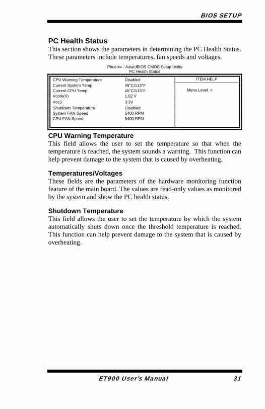
PC Health Status This section shows the parameters in determining the PC Health Status. These parameters include temperatures, fan speeds and voltages.
Phoenix - AwardBIOS CMOS Setup Utility PC Health Status
CPU Warning Temperature Disabled ITEM HELP Current System Temp 45°C/113°F Current CPU Temp 45°C/113°F Menu Level > Vcore(V) 1.02 V Vcc3 3.3V Shutdown Temperature Disabled System FAN Speed 5400 RPM CPU FAN Speed 5400 RPM
CPU Warning Temperature This field allows the user to set the temperature so that when the temperature is reached, the system sounds a warning. This function can help prevent damage to the system that is caused by overheating. Temperatures/Voltages These fields are the parameters of the hardware monitoring function feature of the main board. The values are read-only values as monitored by the system and show the PC health status. Shutdown Temperature This field allows the user to set the temperature by which the system automatically shuts down once the threshold temperature is reached. This function can help prevent damage to the system that is caused by overheating.
BIOS SETUP
32 ET900 User’s Manual
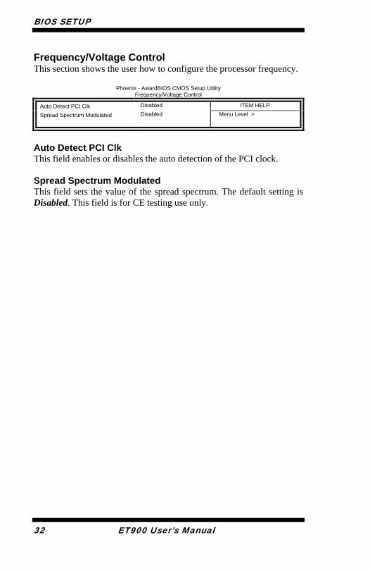
Frequency/Voltage Control This section shows the user how to configure the processor frequency.
Phoenix - AwardBIOS CMOS Setup Utility Frequency/Voltage Control
Auto Detect PCI Clk Disabled ITEM HELP
Spread Spectrum Modulated Disabled Menu Level >
Auto Detect PCI Clk This field enables or disables the auto detection of the PCI clock. Spread Spectrum Modulated This field sets the value of the spread spectrum. The default setting is Disabled. This field is for CE testing use only.
BIOS SETUP
ET900 User’s Manual 33
Load Fail-Safe Defaults This option allows you to load the troubleshooting default values permanently stored in the BIOS ROM. These default settings are non-optimal and disable all high-performance features. Load Optimized Defaults This option allows you to load the default values to your system configuration. These default settings are optimal and enable all high performance features. Set Supervisor Password These two options set the system password. Supervisor Password sets a password that will be used to protect the system and Setup utility. User Password sets a password that will be used exclusively on the system. To specify a password, highlight the type you want and press <Enter>. The Enter Password: message prompts on the screen. Type the password, up to eight characters in length, and press <Enter>. The system confirms your password by asking you to type it again. After setting a password, the screen automatically returns to the main screen.
To disable a password, just press the <Enter> key when you are prompted to enter the password. A message will confirm the password to be disabled. Once the password is disabled, the system will boot and you can enter Setup freely. Save & Exit Setup This option allows you to determine whether or not to accept the modifications. If you type “Y”, you will quit the setup utility and save all changes into the CMOS memory. If you type “N”, you will return to Setup utility. Exit Without Saving Select this option to exit the Setup utility without saving the changes you have made in this session. Typing “Y” will quit the Setup utility without saving the modifications. Typing “N” will return you to Setup utility.

BIOS SETUP
34 ET900 User’s Manual
This page is intentionally left blank.
DRIVERS INSTALLATION
ET900 User’s Manual 35
Drivers Installation
This section describes the installation procedures for software and drivers under the Windows 98SE, Windows ME, Windows 2000 and Windows XP. The software and drivers are included with the main board If you find the items missing, please contact the vendor where you made the purchase. The contents of this section include the following:
Intel Chipset Software Installation Utility......................... 36 VGA Drivers Installation .................................................. 38 AC97 Codec Audio Driver Installation (IP400 carrier board only) .................................................................................. 40 Intel PRO LAN Drivers Installation .................................. 42 Marvell LAN Drivers Installation (IP400 carrier board only) ........................................................................................... 43
IMPORTANT NOTE: After installing your Windows operating system (Windows 98SE/ME/2000/XP), you must install first the Intel Chipset Software Installation Utility before proceeding with the drivers installation.
DRIVERS INSTALLATION
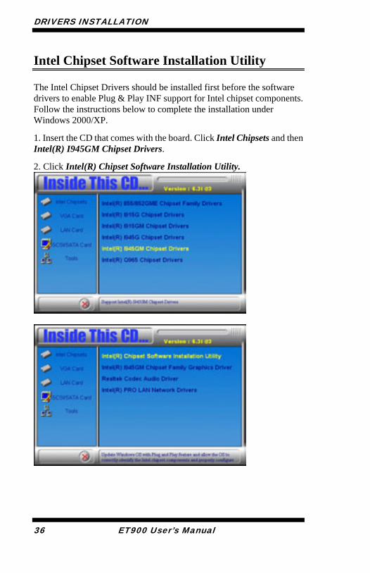
Intel Chipset Software Installation Utility The Intel Chipset Drivers should be installed first before the software drivers to enable Plug & Play INF support for Intel chipset components. Follow the instructions below to complete the installation under Windows 2000/XP.
1. Insert the CD that comes with the board. Click Intel Chipsets and then Intel(R) I945GM Chipset Drivers.
2. Click Intel(R) Chipset Software Installation Utility.
36 ET900 User’s Manual
DRIVERS INSTALLATION
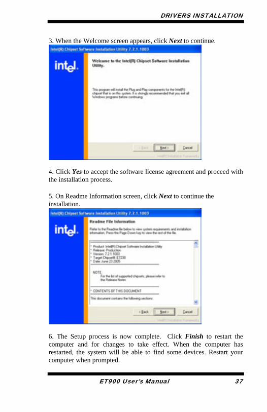
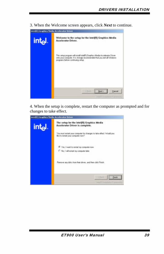
3. When the Welcome screen appears, click Next to continue.
4. Click Yes to accept the software license agreement and proceed with the installation process.
5. On Readme Information screen, click Next to continue the installation.
6. The Setup process is now complete. Click Finish to restart the computer and for changes to take effect. When the computer has restarted, the system will be able to find some devices. Restart your computer when prompted.
ET900 User’s Manual 37
DRIVERS INSTALLATION
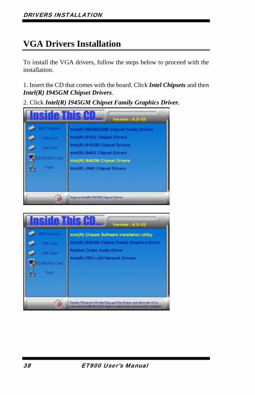
VGA Drivers Installation To install the VGA drivers, follow the steps below to proceed with the installation.
1. Insert the CD that comes with the board. Click Intel Chipsets and then Intel(R) I945GM Chipset Drivers.
2. Click Intel(R) I945GM Chipset Family Graphics Driver.
38 ET900 User’s Manual
DRIVERS INSTALLATION
3. When the Welcome screen appears, click Next to continue.
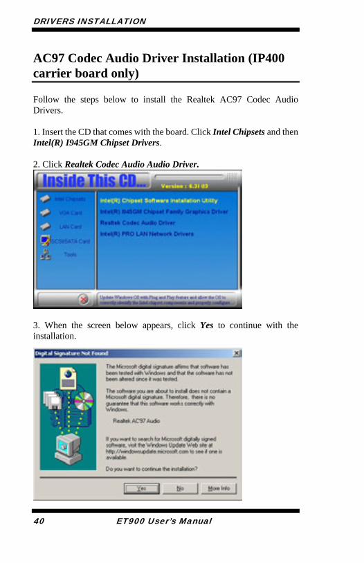
4. When the setup is complete, restart the computer as prompted and for changes to take effect.
ET900 User’s Manual 39
DRIVERS INSTALLATION
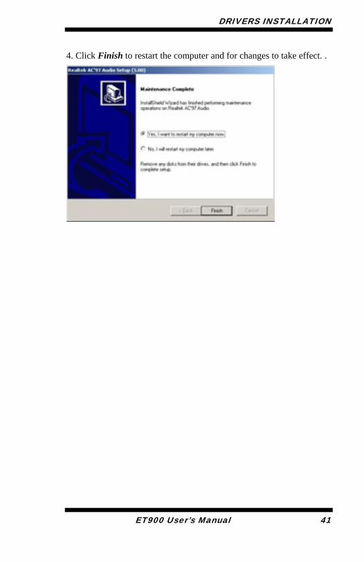
AC97 Codec Audio Driver Installation (IP400 carrier board only) Follow the steps below to install the Realtek AC97 Codec Audio Drivers. 1. Insert the CD that comes with the board. Click Intel Chipsets and then Intel(R) I945GM Chipset Drivers.
2. Click Realtek Codec Audio Audio Driver.
3. When the screen below appears, click Yes to continue with the installation.
40 ET900 User’s Manual
DRIVERS INSTALLATION
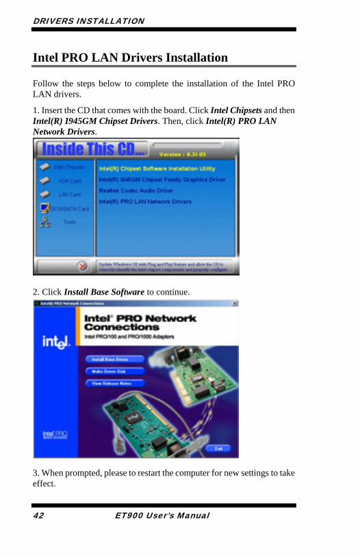
4. Click Finish to restart the computer and for changes to take effect. .
ET900 User’s Manual 41
DRIVERS INSTALLATION
Intel PRO LAN Drivers Installation Follow the steps below to complete the installation of the Intel PRO LAN drivers.
1. Insert the CD that comes with the board. Click Intel Chipsets and then Intel(R) I945GM Chipset Drivers. Then, click Intel(R) PRO LAN Network Drivers.
2. Click Install Base Software to continue.
3. When prompted, please to restart the computer for new settings to take effect.
42 ET900 User’s Manual
DRIVERS INSTALLATION
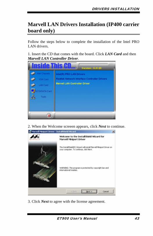
Marvell LAN Drivers Installation (IP400 carrier board only) Follow the steps below to complete the installation of the Intel PRO LAN drivers.
1. Insert the CD that comes with the board. Click LAN Card and then Marvell LAN Controller Driver.
2. When the Welcome screeen appears, click Next to continue.
3. Click Next to agree with the license agreement.
ET900 User’s Manual 43
DRIVERS INSTALLATION
4. When the Readme Information appears, click Next to continue 5. When the Ready to Install the Program appears, click Install to continue.
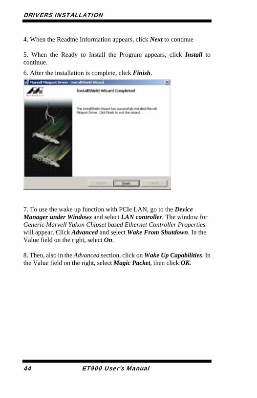
6. After the installation is complete, click Finish.
7. To use the wake up function with PCIe LAN, go to the Device Manager under Windows and select LAN controller. The window for Generic Marvell Yukon Chipset based Ethernet Controller Properties will appear. Click Advanced and select Wake From Shutdown. In the Value field on the right, select On. 8. Then, also in the Advanced section, click on Wake Up Capabilities. In the Value field on the right, select Magic Packet, then click OK.
44 ET900 User’s Manual