Embed Size (px)
Citation preview

© 2007 – 2010, Cisco Systems, Inc. All rights reserved. Cisco Public
ROUTE v6 Chapter 1 1
Chapter 1: Routing Services
CCNP ROUTE: Implementing IP Routing

Chapter 1 2 © 2007 – 2010, Cisco Systems, Inc. All rights reserved. Cisco Public
Chapter 1 Objectives
Describe common enterprise traffic requirements and
network design models.
Describe how to create a plan for implementing routing
services in an enterprise network.
Review the fundamentals of routing and compare various
routing protocols.

Chapter 1 3 © 2007 – 2010, Cisco Systems, Inc. All rights reserved. Cisco Public
Complex Enterprise Network Frameworks, Architectures, and Models

Chapter 1 4 © 2007 – 2010, Cisco Systems, Inc. All rights reserved. Cisco Public
Traffic Conditions in a Converged Network
Modern networks must support various types of traffic:
• Voice and video traffic - IP telephony, video broadcast and conferencing.
• Voice applications traffic - voice-related applications, such as contact centers
• Mission-critical traffic - Generated by applications critical to an organization
• Transactional traffic - Generated by applications such as those for e-commerce.
• Network management traffic -status of the network and its devices.
• Routing protocol traffic
This mix of traffic greatly impacts the network requirements
such as security and performance.
To help enterprises, Cisco has developed the Intelligent
Information Network (IIN).

Chapter 1 5 © 2007 – 2010, Cisco Systems, Inc. All rights reserved. Cisco Public
Cisco Intelligent Information Network
The Intelligent Information Network (IIN):
• Integrates networked resources and information assets.
• Extends intelligence across multiple products and infrastructure layers,
built into each component, network-wide and applies end-to-end.
• Actively participates (manage, monitor, optimize) in the delivery of
services and applications.
• Offers end-to-end functionality and centralized, unified control.
The IIN technology vision consists of 3 three phases in
which functionality can be added to the infrastructure as
required:
• Integrated transport
• Integrated services
• Integrated applications

Chapter 1 6 © 2007 – 2010, Cisco Systems, Inc. All rights reserved. Cisco Public
3 Phases of the IIN Phase 1: Integrated transport
• Integrates data, voice, and video transport into a single, standards-based, modular network simplifying network management and generating enterprise-wide efficiencies.
• Network convergence also lays the foundation for a new class of IP-enabled applications, delivered through Cisco Unified Communications solutions.
Phase 2: Integrated services
• Integrated services help to unify common elements, such as storage and data center server capacity.
• IT resources can now be pooled and shared, or virtualized, to address the changing needs of the organization.
• Business continuity is also enhanced in the event of a local systems failure because shared resources across the IIN can provide needed services.
Phase 3: Integrated applications
This phase focuses on making the network application-aware so that it can optimize application performance and more efficiently deliver networked applications to users.
Application-Oriented Networking(AON) technology and capabilities such as content caching, load balancing, and application-level security allows for integrating intelligent application message handling, optimization, and security into the existing network.

Chapter 1 7 © 2007 – 2010, Cisco Systems, Inc. All rights reserved. Cisco Public
Cisco SONA Framework
The Cisco Service-Oriented Network Architecture (SONA) is
an architectural framework to create a dynamic, flexible
architecture and provide operational efficiency through
standardization and virtualization.
• SONA provides guidance, best practices, and blueprints for
connecting network services and applications to enable business
solutions.
• In this framework, the network is the common element that connects
and enables all components of the IT infrastructure.
SONA help enterprises achieve their goals by leveraging:
• The extensive Cisco product-line services
• The proven Cisco architectures
• The experience of Cisco and its partners

Chapter 1 8 © 2007 – 2010, Cisco Systems, Inc. All rights reserved. Cisco Public
Cisco SONA Framework Layers
The SONA framework outlines three layers:
Application Layer:
Interactive Services Layer:
Network Infrastructure Layer:

Chapter 1 9 © 2007 – 2010, Cisco Systems, Inc. All rights reserved. Cisco Public
SONA: Network Infrastructure Layer
This layer provides
connectivity anywhere and
anytime.
All the IT resources
(servers, storage, and
clients) are interconnected
across a converged network
foundation.
This layer represents how
these resources exist in
different places in the
network (campus, branch, data
center, WAN, MAN and with the
teleworker).

Chapter 1 10 © 2007 – 2010, Cisco Systems, Inc. All rights reserved. Cisco Public
SONA: Interactive Services Layer Enables efficient allocation of
resources to applications and business processes delivered through the networked infrastructure.
Application and business processes include:
• Application Delivery
• Real-time communications
• Voice and collaboration services
• Mobility services
• Security and identity services
• Storage services
• Computer services
• Application networking services
• Network infrastructure virtualization
• Services management
• Adaptive management services

Chapter 1 11 © 2007 – 2010, Cisco Systems, Inc. All rights reserved. Cisco Public
SONA: Application Layer
This layer’s objective is to
meet business requirements
and achieve efficiencies by
leveraging the interactive
services layer.
Includes business
applications and
collaboration applications
such as:
• Commercial applications
• Internally developed applications
• Software as a Services (SaaS)
• Composite Apps/SOA
http://www.cisco.com/go/sona

Chapter 1 12 © 2007 – 2010, Cisco Systems, Inc. All rights reserved. Cisco Public
Updated SONA Framework
Cisco Systems has recently updated the SONA framework: http://www.cisco.com/en/US/netsol/ns629/index.html http://www.cisco.com/en/US/solutions/ns340/ns629/togaf_sona_guide.html
Cisco designs, tests, and validates sets of modular, connected infrastructure elements organized by places in
the network (PINs).
Chapter 1 13 © 2007 – 2010, Cisco Systems, Inc. All rights reserved. Cisco Public
Updated SONA Framework

Chapter 1 14 © 2007 – 2010, Cisco Systems, Inc. All rights reserved. Cisco Public
Cisco Enterprise Architecture
The places in the network in the SONA Network Infrastructure Layer
have been identified as follows:

Chapter 1 15 © 2007 – 2010, Cisco Systems, Inc. All rights reserved. Cisco Public
The Cisco Enterprise Architecture

Chapter 1 16 © 2007 – 2010, Cisco Systems, Inc. All rights reserved. Cisco Public
Campus Architecture
Provides:
High availability with a resilient multilayer design and redundant hardware and software features.
Automatic procedures for reconfiguring network paths when failures occur.
Multicast to provide optimized bandwidth consumption.
Quality of Service (QoS).
Integrated security.
Flexibility to add IP security (IPsec) and MPLS VPNs, identity and access management, and VLANs to compartmentalize access.

Chapter 1 17 © 2007 – 2010, Cisco Systems, Inc. All rights reserved. Cisco Public
Branch Architecture
Provides head-office applications
and services, such as security,
Cisco IP Communications, and
advanced application
performance.
Integrates security, switching,
network analysis, caching, and
converged voice and video
services into a series of
integrated services routers in the
branch.
Enterprises can centrally
configure, monitor, and
manage devices that are located
at remote sites.
Chapter 1 18 © 2007 – 2010, Cisco Systems, Inc. All rights reserved. Cisco Public
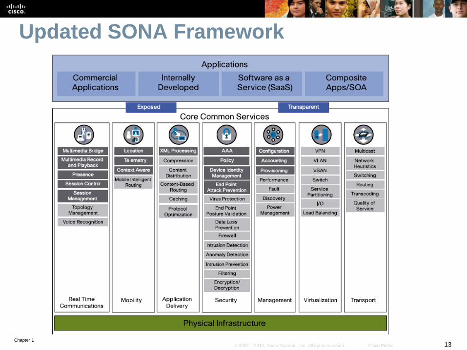
Data Center Architecture
Adaptive network architecture
that supports the requirements
for consolidation, business
continuance, and security.
Redundant data centers provide
backup services using
synchronous and asynchronous
data and application replication.
The network and devices offer
server and application load
balancing to maximize
performance.
This solution allows the
enterprise to scale without major
changes to the infrastructure.

Chapter 1 19 © 2007 – 2010, Cisco Systems, Inc. All rights reserved. Cisco Public
Teleworker Architecture
Also called the Enterprise
Branch-of-One, it allows
enterprises to deliver secure
voice and data services to
remote SOHO offices over a
broadband access service.
Centralized management
minimizes the IT support costs.
Campus security policies are
implemented using robust
integrated security and identity-
based networking services.
• Staff can securely log on to the
network over an always-on VPN
and gain access to authorized
applications and services.

Chapter 1 20 © 2007 – 2010, Cisco Systems, Inc. All rights reserved. Cisco Public
Cisco Hierarchical Network Model
The three-layer hierarchical model is used extensively in
network design.
The hierarchical model consists of the:
• Access layer
• Distribution layer
• Core layer
It provides a modular framework that allows design flexibility
and facilitates implementation and troubleshooting.
• The hierarchical model is useful for smaller networks, but does not
scale well to today’s larger, more complex networks.

Chapter 1 21 © 2007 – 2010, Cisco Systems, Inc. All rights reserved. Cisco Public
Hierarchical Campus Model

Chapter 1 22 © 2007 – 2010, Cisco Systems, Inc. All rights reserved. Cisco Public
Hierarchical Model Applied to a WAN

Chapter 1 23 © 2007 – 2010, Cisco Systems, Inc. All rights reserved. Cisco Public
Enterprise Composite Network Model
The Enterprise Composite Network Model (modular design)
divides the network into three functional areas:
Enterprise Campus Enterprise Edge Service Provider Edge

Chapter 1 24 © 2007 – 2010, Cisco Systems, Inc. All rights reserved. Cisco Public
Enterprise Composite Network Model
Building Access
Building Distribution
Core (Campus backbone)
Server Farm
Management
Edge Distribution
E-Commerce ISP A
Corporate Internet
Remote Access VPN
WAN Frame Relay / ATM
PSTN
ISP B
Enterprise Campus Enterprise Edge Service Provider Edge

Chapter 1 25 © 2007 – 2010, Cisco Systems, Inc. All rights reserved. Cisco Public
Modules in the Enterprise Campus
Building Access
Building Distribution
Core (Campus backbone)
Server Farm
Management
Edge Distribution
E-Commerce ISP A
Corporate Internet
Remote Access VPN
WAN Frame Relay / ATM
PSTN
ISP B
Enterprise Campus Enterprise Edge Service Provider Edge

Chapter 1 26 © 2007 – 2010, Cisco Systems, Inc. All rights reserved. Cisco Public
Modules in the Enterprise Edge
Building Access
Building Distribution
Core (Campus backbone)
Server Farm
Management
Edge Distribution
E-Commerce ISP A
Corporate Internet
Remote Access VPN
WAN Frame Relay / ATM
PSTN
ISP B
Enterprise Campus Enterprise Edge Service Provider Edge

Chapter 1 27 © 2007 – 2010, Cisco Systems, Inc. All rights reserved. Cisco Public
Modules in the Service Provider Edge
Building Access
Building Distribution
Core (Campus backbone)
Server Farm
Management
Edge Distribution
E-Commerce ISP A
Corporate Internet
Remote Access VPN
WAN Frame Relay / ATM
PSTN
ISP B
Enterprise Campus Enterprise Edge Service Provider Edge

Chapter 1 28 © 2007 – 2010, Cisco Systems, Inc. All rights reserved. Cisco Public
Creating, Documenting, and Executing an Implementation Plan

Chapter 1 29 © 2007 – 2010, Cisco Systems, Inc. All rights reserved. Cisco Public
Creating an Implementation Plan
An effective, documented implementation plan is a result of
good processes and procedures during network design,
implementation, and performance testing.
There are two approaches to implementing changes to a
network.
• Ad-hoc approach
• Structured approach

Chapter 1 30 © 2007 – 2010, Cisco Systems, Inc. All rights reserved. Cisco Public
Ad-hoc Approach
The many tasks such as deploying new equipment,
connectivity, addressing, routing, and security are
implemented and configured as required without planning
any of the tasks.
With such an approach, it is more likely that scalability
issues, suboptimal routing, and security issues can occur.
A good implementation plan is required to avoid such
difficulties.
Chapter 1 31 © 2007 – 2010, Cisco Systems, Inc. All rights reserved. Cisco Public
Structured Approach
Prior to implementing a change many considerations are
taken into account.
The design and implementation plan are completed, and
may include a new topology, an IP addressing plan, a
solution to scalability issues, a link utilization upgrade,
remote network connectivity, and changes to other network
parameters.
The design and implementation plan must meet both
technical and business requirements.
All details are documented in the implementation plan prior
to the implementation.
• After successful implementation, the documentation is updated to
include the tools and resources used, and the implementation results.

Chapter 1 32 © 2007 – 2010, Cisco Systems, Inc. All rights reserved. Cisco Public
Models and Methodologies
There are there are many models and methodologies used
in IT that define a lifecycle approach using various
processes to help provide high quality IT services.
• No need to reinvent the wheel.
Examples of these models:
• The Cisco Lifecycle Services (PPDIOO) model. Prepare, Plan, Design,
Implement, Operate, and Optimize
• IT Infrastructure Library (ITIL)
• The Fault, Configuration, Accounting, Performance, and Security
(FCAPS) model
• International Organization for Standardization (ISO)
• The Telecommunications Management Network (TMN) model
• Telecommunications Standardization Sector (ITU-T)
Chapter 1 33 © 2007 – 2010, Cisco Systems, Inc. All rights reserved. Cisco Public
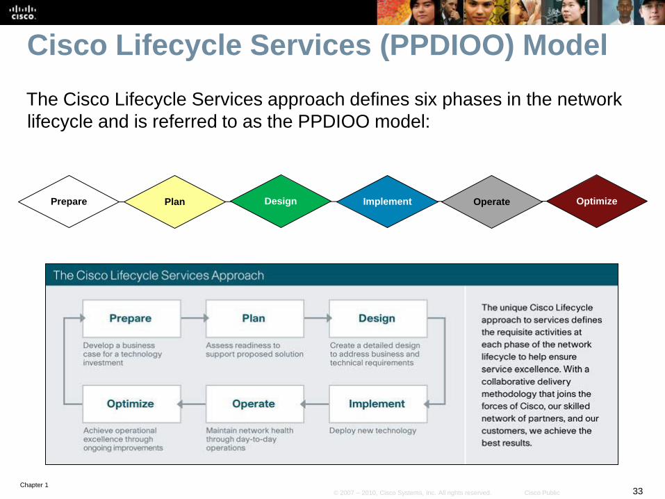
Cisco Lifecycle Services (PPDIOO) Model
The Cisco Lifecycle Services approach defines six phases in the network
lifecycle and is referred to as the PPDIOO model:
Prepare Optimize Plan Design Implement Operate

Chapter 1 34 © 2007 – 2010, Cisco Systems, Inc. All rights reserved. Cisco Public
PPDIOO – Prepare, Plan, and Design
The PPDIOO methodology begins with these three basic
steps:
• Step 1: Identify customer requirements
• Step 2: Characterize the existing network and sites
• Step 3: Design the network topology and solutions
Once the design is defined, the implementation plan can be
executed.
Identify customer
requirements
Design the network
Characterize existing network
Prepare Plan Design

Chapter 1 35 © 2007 – 2010, Cisco Systems, Inc. All rights reserved. Cisco Public
PPDIOO – Implement, Operate, Optimize
The next three steps include:
• Step 4: Plan the implementation:
• Step 5: Implement and verify the design:
• Step 6: Monitor and optionally redesign:
Plan the implementation
Monitor / Redesign Implement and
Verify
Design Implement Operate / Optimize

Chapter 1 36 © 2007 – 2010, Cisco Systems, Inc. All rights reserved. Cisco Public
Implementation Plan documentation
The implementation plan documentation should include the
following:
• Network information
• Tools required
• Resources required
• Implementation plan tasks
• Verification tasks
• Performance measurement and results
• Screen shots and photos, as appropriate
The documentation creation process is not finished until the
end of the project, when the verification information is
added to it.

Chapter 1 37 © 2007 – 2010, Cisco Systems, Inc. All rights reserved. Cisco Public
Sample Implementation Plan
Project contact list and statements of work, to define all of
the people involved and their commitments to the project
Site and equipment location information and details of how
access to the premises is obtained
Tools and resources required
Assumptions made
Tasks to be performed, including detailed descriptions
Network staging plan
Chapter 1 38 © 2007 – 2010, Cisco Systems, Inc. All rights reserved. Cisco Public
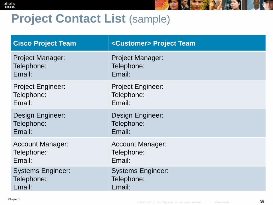
Project Contact List (sample)
Cisco Project Team <Customer> Project Team
Project Manager:
Telephone:
Email:
Project Manager:
Telephone:
Email:
Project Engineer:
Telephone:
Email:
Project Engineer:
Telephone:
Email:
Design Engineer:
Telephone:
Email:
Design Engineer:
Telephone:
Email:
Account Manager:
Telephone:
Email:
Account Manager:
Telephone:
Email:
Systems Engineer:
Telephone:
Email:
Systems Engineer:
Telephone:
Email:

Chapter 1 39 © 2007 – 2010, Cisco Systems, Inc. All rights reserved. Cisco Public
Equipment Floor Plan (sample)
Location Details
Floor
Room
Suite
Position
Rack No.

Chapter 1 40 © 2007 – 2010, Cisco Systems, Inc. All rights reserved. Cisco Public
Tools Required (sample)
Item No. Item
1. PC with Teraterm, 100BaseT interface, FTP Server
and TFTP client applications
2. Console port cable
3. Ethernet cable

Chapter 1 41 © 2007 – 2010, Cisco Systems, Inc. All rights reserved. Cisco Public
Implementation Task List (sample)
Step No. Task
1. Connect to the router
2. Verify the current installation and create backup file
3. Change IOS version (on all routers)
4. Update IP address configuration (on distribution routers)
5. Configure EIGRP routing protocol
6. Verify configuration and record the results

Chapter 1 42 © 2007 – 2010, Cisco Systems, Inc. All rights reserved. Cisco Public
IP Routing Overview

Chapter 1 43 © 2007 – 2010, Cisco Systems, Inc. All rights reserved. Cisco Public
Routing
This section addresses the ways in which routers learn
about networks and how routers can incorporate static and
dynamic routes.
A router can be made aware of remote networks in two
ways:
• An administrator can manually configure the information (static
routing)
• The router can learn from other routers (dynamic routing).
A routing table can contain both static and dynamically
recognized routes.

Chapter 1 44 © 2007 – 2010, Cisco Systems, Inc. All rights reserved. Cisco Public
Static Routes
A static route can be used in the following circumstances:
• To have absolute control of routes used by the router.
• When a backup to a dynamically recognized route is necessary.
• When it is undesirable to have dynamic routing updates forwarded
across slow bandwidth links.
• To reach a stub network.

Chapter 1 45 © 2007 – 2010, Cisco Systems, Inc. All rights reserved. Cisco Public
Static Routing
Configure a static route with the ip route command.
Router(config)#
ip route prefix mask address interface dhcp distance name
next-hop-name permanent track number tag tag
Parameter Description
prefix mask The IP network and subnet mask for the remote network to be entered into the IP routing table.
address The IP address of the next hop that can be used to reach the destination network.
interface The local router outbound interface to be used to reach the destination network.
dhcp (Optional) Enables a Dynamic Host Configuration Protocol (DHCP) server to assign a static route to
a default gateway (option 3).
distance (Optional) The administrative distance to be assigned to this route.
name next-hop-
name (Optional) Applies a name to the specified route.
permanent (Optional) Specifies that the route will not be removed from the routing table even if the interface
associated with the route goes down.
track number (Optional) Associates a track object with this route. Valid values for the number argument range
from 1 to 500.
tag tag (Optional) A value that can be used as a match value in route maps.

Chapter 1 46 © 2007 – 2010, Cisco Systems, Inc. All rights reserved. Cisco Public
Configuring a Default Static Route
R2 is configured with a static route to the R1 LAN and a default static
route to the Internet.
R1 is configured with a default static route.
R1(config)# ip route 0.0.0.0 0.0.0.0 10.1.1.1
R1(config)# exit
R1# show ip route
<output omitted>
Gateway of last resort is not set
C 172.16.1.0 is directly connected, FastEthernet0/0
C 10.1.1.0 is directly connected, Serial0/0/0
S* 0.0.0.0/0 [1/0] via 10.1.1.1
R1#
R2(config)# ip route 172.16.1.0 255.255.255.0 S0/0/0
R2(config)# ip route 0.0.0.0 0.0.0.0 192.168.1.1
Internet
S0/0/0 S0/0/0
Fa0/0 Fa0/0
10.1.1.2 10.1.1.1
192.168.1.2 192.168.1.1 S0/0/1
R1 R2
172.16.1.0 /24 10.2.0.0 /16

Chapter 1 47 © 2007 – 2010, Cisco Systems, Inc. All rights reserved. Cisco Public
Dynamic Routing
Dynamic routing (RIPv1, RIPv2, EIGRP, OSPF, and IS-IS) allows the
network to adjust to changes in the topology automatically,
without administrator involvement.
The information exchanged by routers includes the metric
or cost to each destination (this value is sometimes called
the distance).
• Different routing protocols base their metric on different
measurements, including hop count, interface speed, or more-
complex metrics.

Chapter 1 48 © 2007 – 2010, Cisco Systems, Inc. All rights reserved. Cisco Public
On-Demand Routing
Static routes must be manually configured and updated
when the network topology changes.
Dynamic routing protocols use network bandwidth and
router resources.
• Resource usage of dynamic routing can be considerable.
A third option is to use the Cisco On-Demand Routing
(ODR) feature.
• ODR uses minimal overhead compared to a dynamic routing protocol
and requires less manual configuration than static routes.

Chapter 1 49 © 2007 – 2010, Cisco Systems, Inc. All rights reserved. Cisco Public
ODR
ODR is applicable in a hub-and-spoke topology only.
ODR works with the Cisco Discovery Protocol (CDP) to
carry network information between spokes and hub router.
The hub router sends a default route to the spokes that
points back to itself and installs the stub networks reported
by ODR in its routing table.
• The hub router can then be configured to redistribute the ODR
learned routes into a dynamic routing protocol.

Chapter 1 50 © 2007 – 2010, Cisco Systems, Inc. All rights reserved. Cisco Public
Configuring ODR
ODR is configured:
• On all routers, CDP must be enabled.
• On the hub router using the router odr global config command.
• On the stub routers, no IP routing protocol can be configured.
ODR learned routes appear in the hub router routing table
with an entry of “o” and an administrative distance of 160.
• On each spoke router, the routing table contains only its connected
networks and a static default route injected by ODR from the hub.

Chapter 1 51 © 2007 – 2010, Cisco Systems, Inc. All rights reserved. Cisco Public
Configuring ODR
R1 is a hub router while R2 and R3 are stub routers.
All routers have CDP enabled.
R1(config)# router odr
R1(config)# exit
R1# show ip route
<output omitted>
172.16.0.0/16 is subnetted, 2 subnets
o 172.16.1.0/24 [160/1] via 10.1.1.2, 00:00:23, Serial0/0/1
o 172.16.2.0/24 [160/1] via 10.2.2.2, 00:00:03, Serial0/0/2
<output omitted>
R1#
S0/0/1
10.1.1.2
S0/0/2
R2 R1
172.16.1.0 /24
R3
172.16.2.0 /24
10.2.2.2 10.2.2.1 10.1.1.1

Chapter 1 52 © 2007 – 2010, Cisco Systems, Inc. All rights reserved. Cisco Public
Additional ODR commands.
ODR can also be tuned with optional commands, including:
• a distribute list to filter routing updates
• timers basic router configuration command to adjust ODR timers
• cdp timer global configuration command to adjust the timers and
improve convergence time (default is every 60 seconds).

Chapter 1 53 © 2007 – 2010, Cisco Systems, Inc. All rights reserved. Cisco Public
Distance Vector Versus Link-State
Distance vector:
• Periodic updates: All the routers periodically send their routing tables
(or a portion of their tables) to only their neighboring routers.
• Routers use the received information to determine whether any
changes need to be made to their own routing table.
Link-state routing protocol:
• Triggered updates: Each router sends the state of its own interfaces
(links) to all other routers in an area only when there is a change.
• Each router uses the received information to recalculate the best path
to each network and then saves this information in its routing table.

Chapter 1 54 © 2007 – 2010, Cisco Systems, Inc. All rights reserved. Cisco Public
Classful Versus Classless Routing
Classful Routing Protocol:
• Does not support VLSM.
• Routing updates sent do not include the subnet mask.
• Subnets are not advertised to a different major network.
• Discontiguous subnets are not visible to each other.
• RIP Version 1 (RIPv1) is a classful routing protocol.
Classless Routing Protocol:
• Supports VLSM.
• Routing updates sent include the subnet mask.
• Subnets are advertised to a different major network.
• Discontiguous subnets are visible to each other.
• RIPv2, EIGRP, OSPF, IS-IS, and BGP are classless routing protocols.

Chapter 1 55 © 2007 – 2010, Cisco Systems, Inc. All rights reserved. Cisco Public
Discontiguous Subnets - Classful Routing
Classful routing protocols do not support discontiguous
networks.
Discontiguous subnets are subnets of the same major
network that are separated by a different major network.
• For example, RIPv1 has been configured on all three routers.
• Routers R2 and R3 advertise 172.16.0.0 to R1.
• They cannot advertise the 172.16.1.0 /24 and 172.16.2.0 /24 subnets
across a different major network because RIPv1 is classful.
• R1 therefore receives routes about 172.16.0.0 /16 from two different
directions and it might make an incorrect routing decision.
Fa0/0
R2 R1 172.16.1.0 /24
R3
Fa0/0
172.16.2.0 /24
192.168.2.0 /24 192.168.1.0 /24
RIPv1 update 172.16.0.0
RIPv1 update 172.16.0.0

Chapter 1 56 © 2007 – 2010, Cisco Systems, Inc. All rights reserved. Cisco Public
Discontiguous Subnets - Classless Routing
Classless routing protocols support discontiguous networks.
• For example, RIPv2 has been configured on all three routers.
• Because of RIPv2, routers R2 and R3 can now advertise the
172.16.1.0 /24 and 172.16.2.0 /24 subnets across a different major
network.
• R1 therefore receives routes with valid subnet information and can
now make a correct routing decision.
Fa0/0
R2 R1 172.16.1.0 /24
R3
Fa0/0
172.16.2.0 /24
192.168.2.0 /24 192.168.1.0 /24
RIPv2 update 172.16.1.0/24
RIPv2 update 172.16.2.0/24
R1 Routing Table:
172.16.1.0/24
172.16.2.0/24

Chapter 1 57 © 2007 – 2010, Cisco Systems, Inc. All rights reserved. Cisco Public
ip classless Command
The behavior of a classful routing protocol changes when the ip classless global config command is used.
Classful protocols assume that if the router knows some of
the subnets of a classful network (e.g. 10.0.0.0), then it
must know all that network’s existing subnets.
• If a packet arrives for an unknown destination on the 10.0.0.0 subnet
and:
• ip classless is not enabled, the packet is dropped.
• ip classless is enabled, then the router will follow the best supernet
route or the default route.
Since IOS release 12.0, ip classless is enabled by default and
should not be disabled.

Chapter 1 58 © 2007 – 2010, Cisco Systems, Inc. All rights reserved. Cisco Public
Automatic Route Summarization
Classful routing automatically summarize to the classful
network boundary at major network boundaries.
Classless routing protocols either do not automatically
summarize or automatically summarize but this feature can
be disabled.
• OSPF or IS-IS do not support automatic network summarization.
• RIPv2 and EIGRP perform automatic network summarization to
maintain backward compatibility with RIPv1 and IGRP.
• However, automatic summarization can be disabled in RIPv2 and EIGRP by using the no auto-summary router config command.

Chapter 1 59 © 2007 – 2010, Cisco Systems, Inc. All rights reserved. Cisco Public
Characteristics of Routing Protocols
Characteristics RIPv1 RIPv2 EIGRP IS-IS OSPF BGP
Distance vector
Link-state
Classless
VLSM support
Automatic route
summarization
(can be disabled
using no auto-
summary)
(can be disabled
using no auto-
summary)
Manual route
summarization
Hierarchical
topology required
Size of network Small Small Large Large Large Very large
Metric Hops Hops Composite
metric Metric Cost Path attributes
Convergence time Slow Slow Very fast Fast Fast Slow

Chapter 1 60 © 2007 – 2010, Cisco Systems, Inc. All rights reserved. Cisco Public
Routing Protocol Specifics
Routing Protocol Protocol
Number
Port Number Admin Distance
RIP -- UDP 520 120
IGRP 9 -- 100
EIGRP 88 -- 90
Summary Routes – 5
Redistributed Routes – 170
OSPF 89 -- 110
IS-IS 124 -- 115
BGP -- TCP 179 eBGP – 20
iBGP – 200

Chapter 1 61 © 2007 – 2010, Cisco Systems, Inc. All rights reserved. Cisco Public
Routing Table Criteria The best route selected from various routing protocols for a
specific destination is chosen by considering the following
four criteria:
• Valid next-hop IP address.
• Administrative distance (If more than one route exists for the same
network)
• Metric
• Prefix (If a destination network has different prefix length (different
subnet mask), the routes are all installed in the routing table; the
longest prefix match in the routing table is used for matching)

Chapter 1 62 © 2007 – 2010, Cisco Systems, Inc. All rights reserved. Cisco Public
Administrative Distance
Cisco routers use a value called administrative distance to
select the best path when they learn of two or more routes
to the same destination with the same prefix from different
routing protocols.
Administrative distance rates a routing protocol’s
believability (trustworthy).
Cisco has assigned a default administrative distance value
to each routing protocol supported on its routers.
• Each routing protocol is prioritized in the order of most to least
believable.

Chapter 1 63 © 2007 – 2010, Cisco Systems, Inc. All rights reserved. Cisco Public
Administrative Distances
Route Source Default Distance Routing Table Entry
Connected interface 0 C
Static route out an interface 0 S
Static route to a next-hop address 1 S
EIGRP summary route 5 D
External BGP 20 B
Internal EIGRP 90 D
IGRP 100 I
OSPF 110 O
IS-IS 115 i
RIPv1, RIPv2 120 R
Exterior Gateway Protocol (EGP) 140 E
ODR 160 O
External EIGRP 170 D EX
Internal BGP 200 B
Unknown 255

Chapter 1 64 © 2007 – 2010, Cisco Systems, Inc. All rights reserved. Cisco Public
Floating Static Route
Routers believe static routes over any dynamically learned
route.
To change this default behavior and make a static route
appear in the routing table only when the primary route
goes away, create a floating static route.
• The administrative distance of the static route is configured to be
higher than the administrative distance of the primary route and it
“floats” above the primary route, until the primary route fails.
To configure a static route use the ip route command
with the distance parameter.

Chapter 1 65 © 2007 – 2010, Cisco Systems, Inc. All rights reserved. Cisco Public
Configuring a Floating Static Route
Create floating static routes on R1 and R2 that floats above the EIGRP
learned routes.
R1(config)# ip route 10.0.0.0 255.0.0.0 172.16.1.2 100
R1(config)# router eigrp 1
R1(config-router)# network 172.17.0.0
R1(config-router)# network 192.168.1.0
Internet
Fa0/0 Fa0/0
192.168.1.0 /24
Backup link
R1 R2
172.17.0.0 /16 10.0.0.0 /8
EIGRP 1 Primary link
172.16.1.1 172.16.1.2
R2(config)# ip route 172.17.0.0 255.255.0.0 172.16.1.1 100
R2(config)# router eigrp 1
R2(config-router)# network 10.0.0.0
R2(config-router)# network 192.168.1.0

Chapter 1 66 © 2007 – 2010, Cisco Systems, Inc. All rights reserved. Cisco Public
Routing Within the ECNM Routing protocols are an integral part of any network.
• When designing a network routing protocol, selection and planning
are among the design decisions to be made.
Although the best practice is to use one IP routing protocol
throughout the enterprise if possible, in some cases multiple
routing protocols might be required.

Chapter 1 67 © 2007 – 2010, Cisco Systems, Inc. All rights reserved. Cisco Public
Suggested Routing Protocols Used
Building Access
Building Distribution
Core (Campus backbone)
Server Farm
Edge Distribution
RIPv2, OSPF, EIGRP, Static routes
OSPF, EIGRP, IS-IS and BGP
Between Building Access and Building Distribution:
Between Building Distribution and Core:

Chapter 1 68 © 2007 – 2010, Cisco Systems, Inc. All rights reserved. Cisco Public
Routing Within the ECNM The Enterprise Composite Network Model can assist in
determining where each routing protocol is implemented,
where the boundaries between protocols are, and how
traffic flows between them will be managed.

Chapter 1 69 © 2007 – 2010, Cisco Systems, Inc. All rights reserved. Cisco Public
Chapter 1 Summary
Traffic in converged networks includes voice and video, voice applications,
mission-critical, transactional, routing protocol, and network management.
The three phases of the Cisco IIN: integrated transport, integrated services, and
integrated applications.
The three layers of the Cisco SONA architectural framework: networked
infrastructure, interactive services, application.
The components of the Cisco Enterprise Architecture for integration of the entire
network: campus, data center, branches, teleworkers, and WAN.
The traditional hierarchical network model with its three layers: core, distribution,
and access.
The Cisco Enterprise Composite Network Model with its three functional areas
and their associated modules:
• Enterprise Campus: Building, Building Distribution, Core, Edge Distribution, Server Farm,
Management
• Enterprise Edge: E-commerce, Corporate Internet, VPN and Remote Access, WAN
• Service Provider Edge: ISP, PSTN, Frame Relay/ATM.

Chapter 1 70 © 2007 – 2010, Cisco Systems, Inc. All rights reserved. Cisco Public
Chapter 1 Summary (continued)
The two approaches to implementing changes to a network: using an
ad-hoc approach or using a structured approach.
Four models used in IT services lifecycles: Cisco Lifecycle Services
(PPDIOO), ITIL, FCAPS, and TMN.
Creating an implementation plan, as part of the network Design phase,
that includes:
• Network information
• Tools required
• Resources required
• Implementation plan tasks
• Verification tasks
• Performance measurement and results}

Chapter 1 71 © 2007 – 2010, Cisco Systems, Inc. All rights reserved. Cisco Public
Chapter 1 Summary (continued)
Static routing characteristics and configuration.
Characteristics and configuration of ODR, which uses CDP to carry network information between spoke
(stub) routers and the hub router.
Dynamic routing protocol characteristics, including:
• The metric, a value (such as path length) that routing protocols use to measure paths to a destination.
• Configuration, using the router protocol global configuration command.
• Distance vector routing, in which all the routers periodically send their routing tables (or a portion of their tables) to
only their neighboring routers.
• Link-state routing, in which each of the routers sends the state of its own interfaces (its links) to all other routers (or to
all routers in a part of the network, known as an area) only when there is a change.
• Hybrid routing, in which routers send only changed information when there is a change (similar to link-state protocols)
but only to neighboring routers (similar to distance vector protocols).
• Classful routing protocol updates, which do not include the subnet mask. Classful protocols do not support VLSM or
discontiguous subnets and must automatically summarize across the network boundary to the classful address.
• Classless routing protocol updates, which do include the subnet mask. Classless protocols do support VLSM and
discontiguous subnets, and do not have to summarize automatically across network boundaries.
The process that Cisco routers use to populate their routing tables includes a valid next-hop IP
address, Administrative distance, metric, and prefix.

Chapter 1 72 © 2007 – 2010, Cisco Systems, Inc. All rights reserved. Cisco Public
Lab 1-1 Tcl Script Reference and Demonstration
Chapter 1 Labs
Chapter 1 73 © 2007 – 2010, Cisco Systems, Inc. All rights reserved. Cisco Public