Embed Size (px)
Citation preview
AAiT, School of Civil and Environmental Engineering Reinforced Concrete I
Chapter 1 – Introduction to Reinforced Concrete Page 1
CHAPTER 1. INTRODUCTON TO REINFORCED CONCRETE
1.1. INTRODUCTION
Traditionally, the study of reinforced concrete design begins directly with a chapter on materials,
followed by chapters dealing with design. In this material, a departure is made from that
convention. It is desirable for the student to have first an overview of the world of reinforced
concrete structures, before plunging into the finer details of the subject. Accordingly, this section
gives a general introduction to reinforced concrete and its applications. It also explains the role
of structural design in reinforced concrete construction, and outlines the various structural
systems that are commonly adopted in buildings.
That concrete is a common structural material is, no doubt, well known. But, how common it is,
and how much a part of our daily lives it plays, is perhaps not well known — or rather, not often
realized. Structural concrete is used extensively in the construction of various kinds of buildings,
stadia, auditoria, pavements, bridges, piers, breakwaters, berthing structures, dams, waterways,
pipes, water tanks, swimming pools, cooling towers, bunkers and silos, chimneys,
communication towers, tunnels, etc. It is the most commonly used construction material,
consumed at a rate of approximately one ton for every living human being. “Man consumes no
material except water in such tremendous quantities”.
1.2. PLAIN AND REINFORCED CONCRETE
1.2.1. PLAIN CONCRETE
Concrete may be defined as any solid mass made by the use of a cementing medium; the
ingredients generally comprise sand, gravel, cement and water. That the mixing together of such
disparate and discrete materials can result in a solid mass (of any desired shape), with well-
defined properties, is a wonder in itself. Concrete has been in use as a building material for more
than a hundred and fifty years. Its success and popularity may be largely attributed to (1)
durability under hostile environments (including resistance to water), (2) ease with which it can
be cast into a variety of shapes and sizes, and (3) its relative economy and easy availability. The
main strength of concrete lies in its compression-bearing ability, which surpasses that of
traditional materials like brick and stone masonry. Advances in concrete technology, during the
AAiT, School of Civil and Environmental Engineering Reinforced Concrete I
Chapter 1 – Introduction to Reinforced Concrete Page 2
past four decades in particular, have now made it possible to produce a wide range of concrete
grades, varying in mass density (1200−2500 kg/m3) and compressive strength (10 −100 MPa).
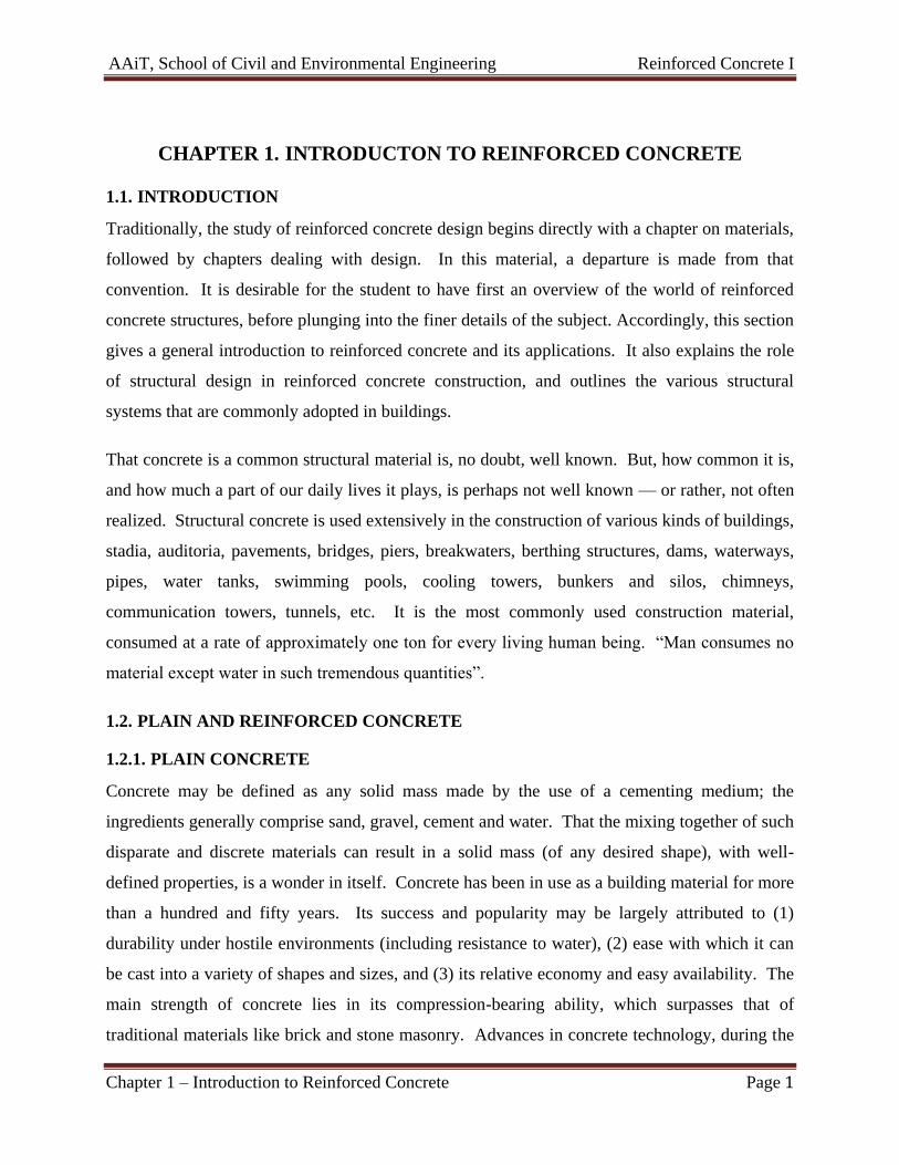
Concrete may be remarkably strong in compression, but it is equally remarkably weak in tension
[Figure 1-1(a)]. Its tensile strength is approximately one-tenth of its compressive strength.
Hence, the use of plain concrete as a structural material is limited to situations where significant
tensile stresses and strains do not develop, as in hollow (or solid) block wall construction, small
pedestals and ‘mass concrete’ applications (in dams, etc.).
1.2.2. REINFORCED CONCRETE
Concrete would not have gained its present status as a principal building material, but for the
invention of reinforced concrete, which is concrete with steel bars embedded in it. The idea of
reinforcing concrete with steel has resulted in a new composite material, having the potential of
resisting significant tensile stresses, which was hitherto impossible. Thus, the construction of
load-bearing flexural members, such as beams and slabs, became viable with this new material.
Its utility and versatility are achieved by combining the best features of concrete and steel.
Consider some of the widely differing properties of these two materials that are listed below in
Table 1-1.
Table 1-1- Complementary properties of Concrete and Steel
Concrete Steel
Strength in Tension Poor Good
Strength in Compression Good Good, but slender bars will buckle
Strength in Shear Fair Good
Durability Good Corrodes if unprotected
Fire resistance Good Poor, suffers rapid loss of strength at high temperature
It can be seen from this list that the materials are more or less compatible. The steel bars
(embedded in the tension zone of the concrete) compensate for the concrete’s incapacity for
tensile resistance, effectively taking up all the tension, without separating from the concrete
[Figure 1-1(b)]. The bond between steel and the surrounding concrete ensures strain
compatibility, i.e., the strain at any point in the steel is equal to that in the adjoining concrete.
Moreover, the reinforcing steel imparts ductility to a material that is otherwise brittle. In
AAiT, School of Civil and Environmental Engineering Reinforced Concrete I
Chapter 1 – Introduction to Reinforced Concrete Page 3
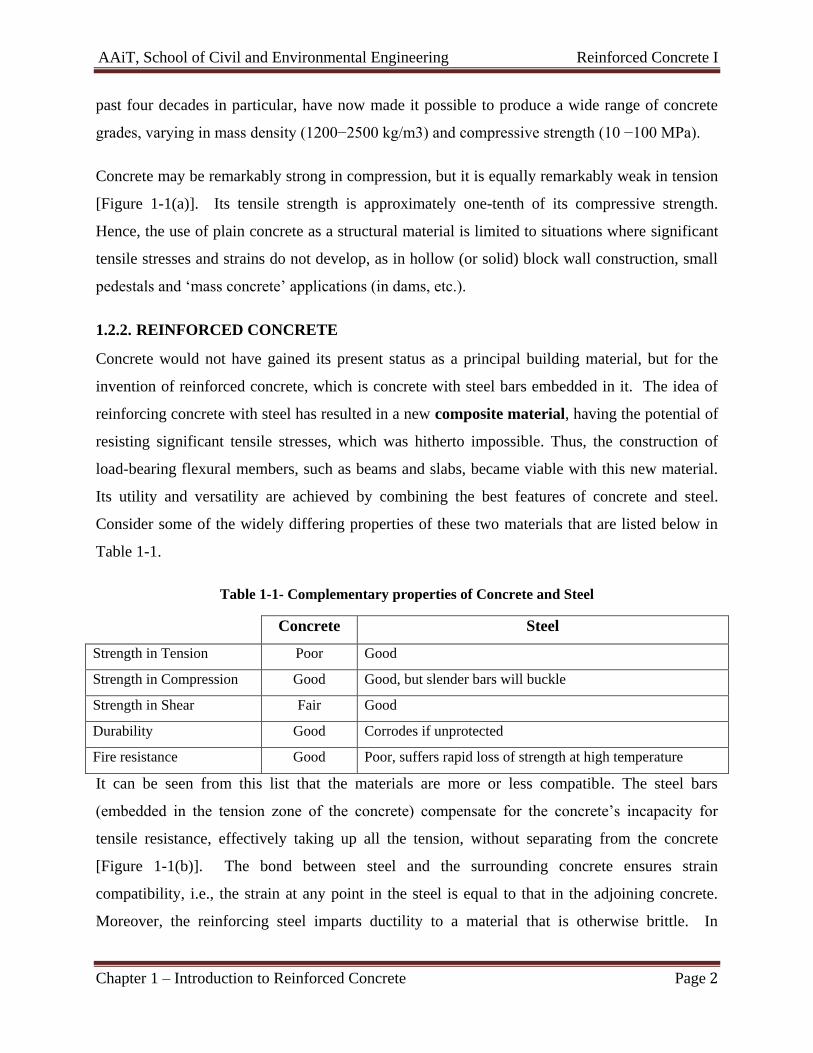
practical terms, this implies that if a properly reinforced beam were to fail in tension, then such a
failure would, fortunately, be preceded by large deflections caused by the yielding of steel,
thereby giving ample warning of the impending collapse [Figure 1-1(c)].
Tensile stresses occur either directly, as in direct tension or flexural tension, or indirectly, as in
shear, which causes tension along diagonal planes (‘diagonal tension’). Temperature and
shrinkage effects may also induce tensile stresses. In all such cases, reinforcing steel is essential,
and should be appropriately located, in a direction that cuts across the principal tensile planes
(i.e., across potential tensile cracks). If insufficient steel is provided, cracks would develop and
propagate, and could possibly lead to failure.
Reinforcing steel can also supplement concrete in bearing compressive forces, as in columns
provided with longitudinal bars. These bars need to be confined by transverse steel ties [Figure
1-1(d)], in order to maintain their positions and to prevent their lateral buckling. The lateral ties
also serve to confine the concrete, thereby enhancing its compression load-bearing capacity.
The development of reliable design and construction techniques has enabled the construction of a
wide variety of reinforced concrete structures all over the world: building frames (columns and
beams), floor and roof slabs, foundations, bridge decks and piers, retaining walls, grandstands,
water tanks, pipes, bunkers and silos, folded plates and shells, etc.
(a) Plain concrete beam
cracks and fails in
flexural tension under a
small load
(b) Reinforced concrete
beam supports loads
with acceptably low
deformations
AAiT, School of Civil and Environmental Engineering Reinforced Concrete I
Chapter 1 – Introduction to Reinforced Concrete Page 4
(c) Ductile mode of failure
under heavy loads
(d) Reinforced concrete
column
Figure 1-1 - Contribution of steel bars in reinforced concrete
1.3. ADVANTAGES AND DISADVANTAGES OF REINFORCED CONCRETE FOR A
STRUCTURE
The choice of whether a structure should be built of reinforced concrete, steel, masonry, or
timber depends on the availability of materials and on a number of value decisions.
1. Economy.
2. Suitability of material for architectural and structural function.
3. Fire resistance.
4. Rigidity.
5. Low maintenance.
6. Availability of materials.
On the other hand, there are a number of factors that may cause one to select a material other
than reinforced concrete. These include:
1. Low tensile strength.
2. Forms and shoring.
AAiT, School of Civil and Environmental Engineering Reinforced Concrete I
Chapter 1 – Introduction to Reinforced Concrete Page 5
3. Relatively low strength per unit of weight or volume.
4. Time-dependent volume changes.
1.4. THE DESIGN PROCESS
1.4.1. OBJECTIVES OF DESIGN
A structural engineer is a member of a team that works together to design a building, bridge, or
other structure. In the case of a building, an architect generally provides the overall lay-out, and
mechanical, electrical, and structural engineers design individual systems within the building.
The structure should satisfy four major criteria:
1. Appropriateness.
2. Economy.
3. Structural adequacy.
4. Maintainability
1.4.2. THE DESIGN PROCESS
The design process is a sequential and iterative decision-making process. The three major phases
are the following:
1. Definition of the client’s needs and priorities.
2. Development of project concept
3. Design of individual systems.
1.5. DESIGN CODES AND HANDBOOKS
1.5.1. PURPOSE OF CODES
National building codes have been formulated in different countries to lay down guidelines for
the design and construction of structures. The codes have evolved from the collective wisdom of
expert structural engineers, gained over the years. These codes are periodically revised to bring
them in line with current research, and often, current trends.
The codes serve at least four distinct functions:
1. They ensure adequate structural safety, by specifying certain essential minimum
requirements for design.
AAiT, School of Civil and Environmental Engineering Reinforced Concrete I
Chapter 1 – Introduction to Reinforced Concrete Page 6
2. They render the task of the designer relatively simple; often, the results of sophisticated
analyses are made available in the form of a simple formula or chart.
3. The codes ensure a measure of consistency among different designers.
4. They have some legal validity, in that they protect the structural designer from any
liability due to structural failures that are caused by inadequate supervision and/or
faulty material and construction.
The codes are not meant to serve as a substitute for basic understanding and engineering
judgment. The student is, therefore, forewarned that s/he will make a poor designer if s/he
succumbs to the unfortunate (and all-too-common) habit of blindly following the codes. On the
contrary, in order to improve her/his understanding, s/he must learn to question the code
provisions — as, indeed, s/he must, nearly everything in life!
1.5.2. INTRODUCTION TO EUROCODES
The development of the Eurocodes started in 1975; since then they have evolved significantly
and are now claimed to be the most technically advanced structural codes in the world. There are
ten Eurocodes covering all the main structural materials (see Figure 1-2). The structural
Eurocodes were initiated by the European Commission but are now produced by the Comité
Européen de Normalisation (CEN) which is the European standards organization. CEN is
publishing the design standards as full European Standards EN (Euronorms):
EN 1990: Eurocode: Basis of design (EC0)
EN 1991: Eurocode 1 Actions on structures (EC1)
Part 1-1: General actions – Densities, self-weight and imposed loads
Part 1-2: General actions on structures exposed to fire
Part 1-3: General actions – Snow loads
Part 1-4: General actions – Wind loads
Part 1-5: General actions – Thermal actions
Part 1-6: Actions during execution
Part 1-7: Accidental actions from impact and explosions
Part 2: Traffic loads on bridges
Part 3: Actions induced by cranes and machinery
AAiT, School of Civil and Environmental Engineering Reinforced Concrete I
Chapter 1 – Introduction to Reinforced Concrete Page 7
Part 4: Actions in silos and tanks
EN 1992: Eurocode 2: Design of concrete structures (EC2)
Part 1-1: General rules and rules for buildings (EC2 Part 1-1)
Part 1-2: General rules - Structural fire design (EC2 Part 1-2)
Part 2: Reinforced and pre-stressed concrete bridges (EC2 Part 2)
Part 3: Liquid retaining and containing structures (EC2 Part 3)
EN 1993: Eurocode 3: Design of steel structures (EC3)
EN 1994: Eurocode 4: Design of composite steel and concrete structures (EC4)
EN 1995: Eurocode 5: Design of timber structures (EC5)
EN 1996: Eurocode 6: Design of masonry structures (EC6)
EN 1997: Eurocode 7: Geotechnical design (EC7)
EN 1998: Eurocode 8: Earthquake resistant design of structures (EC8)
EN 1999: Eurocode 9: Design of aluminum alloy structures (EC9)
All Eurocodes follow a common editorial style. The codes contain ‘Principles’ and ‘Application
rules’. Principles are identified by the letter P following the paragraph number. Principles
are general statements and definitions for which there is no alternative, as well as,
requirements and analytical models for which no alternative is permitted unless specifically
stated.
Application rules are generally recognized rules which comply with the Principles and
satisfy their requirements. Alternative rules may be used provided that compliance with
the Principles can be demonstrated, however the resulting design cannot be claimed to be wholly
in accordance with the Eurocode although it will remain in accordance with Principles.
1. Eurocode: Basis of structural design
In the Eurocode system EN 1990, Eurocode: Basis of Structural Design overarches all the other
Eurocodes (EN 1991 to EN 1999). EN 1990 defines the effects of actions, including geotechnical
and seismic actions, and applies to all structures irrespective of the material of construction. The
material Eurocodes define how the effects of actions are resisted by giving rules for design and
detailing of concrete, steel, composite, timber, masonry and aluminum. (See Figure 1-2).
AAiT, School of Civil and Environmental Engineering Reinforced Concrete I
Chapter 1 – Introduction to Reinforced Concrete Page 8
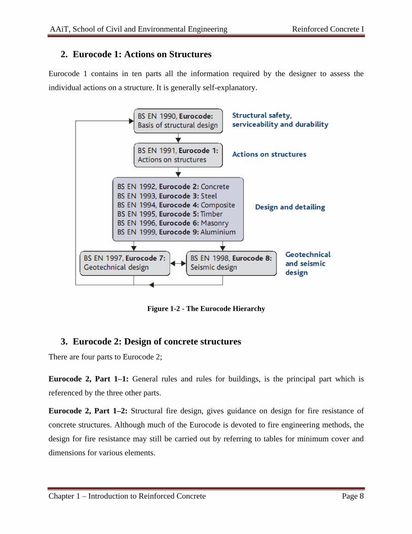
2. Eurocode 1: Actions on Structures
Eurocode 1 contains in ten parts all the information required by the designer to assess the
individual actions on a structure. It is generally self-explanatory.
Figure 1-2 - The Eurocode Hierarchy
3. Eurocode 2: Design of concrete structures
There are four parts to Eurocode 2;
Eurocode 2, Part 1–1: General rules and rules for buildings, is the principal part which is
referenced by the three other parts.
Eurocode 2, Part 1–2: Structural fire design, gives guidance on design for fire resistance of
concrete structures. Although much of the Eurocode is devoted to fire engineering methods, the
design for fire resistance may still be carried out by referring to tables for minimum cover and
dimensions for various elements.
AAiT, School of Civil and Environmental Engineering Reinforced Concrete I
Chapter 1 – Introduction to Reinforced Concrete Page 9
Eurocode 2, Part 2: Bridges, applies the general rules given in Part 1–1 to the design of
concrete bridges. As a consequence both Part 1–1 and Part 2 will be required to carry out a
design of a reinforced concrete bridge.
Eurocode 2, Part 3: Liquid retaining and containment structures, applies the general rules given
in Part 1–1 to the liquid-retaining structures.
1.6. DESIGN PHILOSOPHIES
1.6.1. INTRODUCTION
Over the years, various design philosophies have evolved in different parts of the world, with
regard to reinforced concrete design. A ‘design philosophy’ is built up on a few fundamental
premises (assumptions), and is reflective of a way of thinking.
The earliest codified design philosophy is the working stress method of design (WSM). Close
to a hundred years old, this traditional method of design, based on linear elastic theory, is still
surviving in some countries, although it is now sidelined by the modern limit states design
philosophy.
Historically, the design procedure to follow the WSM was the ultimate load method of design
(ULM), which was developed in the 1950s. Based on the (ultimate) strength of reinforced
concrete at ultimate loads, it evolved and gradually gained acceptance. This method was
introduced as an alternative to WSM in the ACI code in 1956 and the British Code in 1957.
Probabilistic concepts of design developed over the years and received a major impetus from the
mid-1960s onwards. The philosophy was based on the theory that the various uncertainties in
design could be handled more rationally in the mathematical framework of probability theory.
The risk involved in the design was quantified in terms of a probability of failure. Such
probabilistic methods came to be known as reliability-based methods. However, there was
little acceptance for this theory in professional practice, mainly because the theory appeared to
be complicated and intractable (mathematically and numerically).
In order to gain code acceptance, the probabilistic ‘reliability-based’ approach had to be
simplified and reduced to a deterministic format involving multiple (partial) safety factors (rather
than probability of failure). The European Committee for Concrete (CEB) and the International
Federation for Pre-stressing (FIP) were among the earliest to introduce the philosophy of limit
AAiT, School of Civil and Environmental Engineering Reinforced Concrete I
Chapter 1 – Introduction to Reinforced Concrete Page 10
states method (LSM) of design, which is reliability-based in concept. Based on the CEB-FIP
recommendations, LSM was introduced in the British Code CP 110 (1973). In the United States,
LSM was introduced in a slightly different format (strength design and serviceability design) in
the ACI 318−71 (now ACI 318-95).
Thus, the past several decades have witnessed an evolution in design philosophy — from the
traditional ‘working stress method’, through the ‘ultimate load method’, to the modern ‘limit
states method’ of design.
1.6.2. WORKING STRESS METHOD (WSM)
This was the traditional method of design not only for reinforced concrete, but also for structural
steel and timber design. The conceptual basis of WSM is simple. The method basically assumes
that the structural material behaves in a linear elastic manner, and that adequate safety can be
ensured by suitably restricting the stresses in the material induced by the expected ‘working
loads’ (service loads) on the structure. As the specified permissible (‘allowable’) stresses are
kept well below the material strength (i.e., in the initial phase of the stress-strain curve), the
assumption of linear elastic behavior is considered justifiable. The ratio of the strength of the
material to the permissible stress is often referred to as the factor of safety.
The stresses under the applied loads are analyzed by applying the methods of ‘strength of
materials’ such as the simple bending theory. In order to apply such methods to a composite
material like reinforced concrete, strain compatibility (due to bond) is assumed, whereby the
strain in the reinforcing steel is assumed to be equal to that in the adjoining concrete to which it
is bonded. Furthermore, as the stresses in concrete and steel are assumed to be linearly related to
their respective strains, it follows that the stress in steel is linearly related to that in the adjoining
concrete by a constant factor (called the modular ratio), defined as the ratio of the modulus of
elasticity of steel to that of concrete.
However, the main assumption of linear elastic behavior and the tacit assumption that the
stresses under working loads can be kept within the ‘permissible stresses’ are not found to be
realistic. Many factors are responsible for this — such as the long-term effects of creep and
shrinkage, the effects of stress concentrations, and other secondary effects. All such effects
result in significant local increases in and redistribution of the calculated stresses. Moreover,
WSM does not provide a realistic measure of the actual factor of safety underlying a design.
AAiT, School of Civil and Environmental Engineering Reinforced Concrete I
Chapter 1 – Introduction to Reinforced Concrete Page 11
WSM also fails to discriminate between different types of loads that act simultaneously, but have
different degrees of uncertainty. This can, at times, result in very unconservative designs,
particularly when two different loads (say, dead loads and wind loads) have counteracting
effects.
Nevertheless, in defense against these and other shortcomings leveled against WSM, it may be
stated that most structures designed in accordance with WSM have been generally performing
satisfactorily for many years. The design usually results in relatively large sections of structural
members (compared to ULM and LSM), thereby resulting in better serviceability performance
(less deflections, crack-widths, etc.) under the usual working loads. The method is also notable
for its essential simplicity — in concept, as well as application.
1.6.3. ULTIMATE LOAD METHOD (ULM)
With the growing realization of the shortcomings of WSM in reinforced concrete design, and
with increased understanding of the behavior of reinforced concrete at ultimate loads, the
ultimate load method of design (ULM) evolved in the 1950s and became an alternative to WSM.
This method is sometimes also referred to as the load factor method or the ultimate strength
method.
In this method, the stress condition at the state of impending collapse of the structure is analyzed,
and the non-linear stress−strain curves of concrete and steel are made use of. The concept of
‘modular ratio’ and its associated problems are avoided entirely in this method. The safety
measure in the design is introduced by an appropriate choice of the load factor, defined as the
ratio of the ultimate load (design load) to the working load. The ultimate load method makes it
possible for different types of loads to be assigned different load factors under combined loading
conditions, thereby overcoming the related shortcoming of WSM.
This method generally results in more slender sections, and often more economical designs of
beams and columns (compared to WSM), particularly when high strength reinforcing steel and
concrete are used.
However, the satisfactory ‘strength’ performance at ultimate loads does not guarantee
satisfactory ‘serviceability’ performance at the normal service loads. The designs sometimes
AAiT, School of Civil and Environmental Engineering Reinforced Concrete I
Chapter 1 – Introduction to Reinforced Concrete Page 12
result in excessive deflections and crack-widths under service loads, owing to the slender
sections resulting from the use of high strength reinforcing steel and concrete.
1.6.4. LIMIT STATES METHOD (LSM)
The philosophy of the limit states method of design (LSM) represents a definite advancement
over the traditional design philosophies. Unlike WSM, which based calculations on service load
conditions alone, and unlike ULM, which based calculations on ultimate load conditions alone,
LSM aims for a comprehensive and rational solution to the design problem, by considering
safety at ultimate loads and serviceability at working loads.
The LSM philosophy uses a multiple safety factor format which attempts to provide adequate
safety at ultimate loads as well as adequate serviceability at service loads, by considering all
possible ‘limit states’ (defined in the next section). The selection of the various multiple safety
factors is supposed to have a sound probabilistic basis, involving the separate consideration of
different kinds of failure, types of materials and types of loads. In this sense, LSM is more than
a mere extension of WSM and ULM. It represents a new ‘paradigm’ — a modern philosophy.
1. Limit States
When a structure or structural element becomes unfit for its intended use, it is said to have
reached a limit state. The limit states for reinforced concrete structures can be divided into three
basic groups:
I. Ultimate limit states. These involve a structural collapse of part or all of the structure.
Such a limit state should have a very low probability of occurrence, because it may lead
to loss of life and major financial losses. The major ultimate limit states are as follows:
a) Loss of equilibrium of a part or all of the structure as a rigid body. Such a failure would
generally involve tipping or sliding of the entire structure and would occur if the
reactions necessary for equilibrium could not be developed.
b) Rupture of critical parts of the structure, leading to partial or complete collapse. The
majority of this document deals with this limit state. Chapters 3 consider flexural failures;
Chapter 4 shear failures; and so on.
AAiT, School of Civil and Environmental Engineering Reinforced Concrete I
Chapter 1 – Introduction to Reinforced Concrete Page 13
c) Progressive collapse. In some structures, an overload on one member may cause that
member to fail. The load acting on it is transferred to adjacent members which, in turn,
may be overloaded and fail, causing them to shed their load to adjacent members, causing
them to fail one after another, until a major part of the structure has collapsed. This is
called a progressive collapse. Progressive collapse is prevented, or at least is limited, by
one or more of the following:
i. Controlling accidental events by taking measures such as protection against
vehicle collisions or explosions.
ii. Providing local resistance by designing key members to resist accidental events.
iii. Providing minimum horizontal and vertical ties to transfer forces.
iv. Providing alternative lines of support to anchor the tie forces.
v. Limiting the spread of damage by subdividing the building with planes of
weakness sometimes referred to as structural fuses.
A structure is said to have general structural integrity if it is resistant to progressive collapse. For
example, an explosion or a vehicle collision may accidentally remove a column that supports an
interior support of a two-span continuous beam. If properly detailed, the structural system may
change from two spans to one long span. This would entail large deflections and a change in the
load path from beam action to catenary or tension membrane action. Most building Codes
require continuous ties of tensile reinforcement around the perimeter of the building at each floor
to reduce the risk of progressive collapse. The ties provide reactions to anchor the catenary
forces and limit the spread of damage. Because such failures are most apt to occur during
construction, the designer should be aware of the applicable construction loads and procedures.
d) Formation of a plastic mechanism. A mechanism is formed when the reinforcement
yields to form plastic hinges at enough sections to make the structure unstable.
e) Instability due to deformations of the structure. This type of failure involves buckling
f) Fatigue. Fracture of members due to repeated stress cycles of service loads may cause
collapse.
II. Serviceability limit states. These involve disruption of the functional use of the
structure, but not collapse. Because there is less danger of loss of life, a higher
probability of occurrence can generally be tolerated than in the case of an ultimate limit
state. Design for serviceability is discussed in Chapter 4. The major serviceability limit
states include the following:
AAiT, School of Civil and Environmental Engineering Reinforced Concrete I
Chapter 1 – Introduction to Reinforced Concrete Page 14
a) Excessive deflections for normal service. Excessive deflections may cause machinery
to malfunction, may be visually unacceptable, and may lead to damage to nonstructural
elements or to changes in the distribution of forces. In the case of very flexible roofs,
deflections due to the weight of water on the roof may lead to increased depth of water,
increased deflections, and so on, until the strength of the roof is exceeded. This is a
ponding failure and in essence is a collapse brought about by failure to satisfy a
serviceability limit state.
b) Excessive crack widths. Although reinforced concrete must crack before the
reinforcement can function effectively, it is possible to detail the reinforcement to
minimize the crack widths. Excessive crack widths may be unsightly and may allow
leakage through the cracks, corrosion of the reinforcement, and gradual deterioration of
the concrete.
c) Undesirable vibrations. Vertical vibrations of floors or bridges and lateral and
torsional vibrations of tall buildings may disturb the users. Vibration effects have rarely
been a problem in reinforced concrete buildings.
III. Special limit states. This class of limit states involves damage or failure due to abnormal
conditions or abnormal loadings and includes:
a) Damage or collapse in extreme earthquakes,
b) Structural effects of fire, explosions, or vehicular collisions,
c) Structural effects of corrosion or deterioration, and
d) Long-term physical or chemical instability (normally not a problem with
concrete structures).
2. Limit state design process
Limit-states design is a process that involves
1. The identification of all potential modes of failure (i.e., identification of the significant
limit states),
2. The determination of acceptable levels of safety against occurrence of each limit state,
3. Structural design for the significant limit states.
For normal structures, step 2 is carried out by the building-code authorities, who specify the load
combinations and the load factors to be used. For unusual structures, the engineer may need to
AAiT, School of Civil and Environmental Engineering Reinforced Concrete I
Chapter 1 – Introduction to Reinforced Concrete Page 15
check whether the normal levels of safety are adequate. For buildings, a limit-states design starts
by selecting the concrete strength, cement content, cement type, supplementary cementitious
materials, water–cementitious materials ratio, air content, and cover to the reinforcement to
satisfy the durability requirements of Eurocode. Next, the minimum member sizes and minimum
covers are chosen to satisfy the fire-protection requirements of the local building code. Design is
then carried out, starting by proportioning for the ultimate limit states followed by a check of
whether the structure will exceed any of the serviceability limit states. This sequence is followed
because the major function of structural members in buildings is to resist loads without
endangering the occupants. For a water tank, however, the limit state of excessive crack width is
of equal importance to any of the ultimate limit states if the structure is to remain watertight. In
such a structure, the design for the limit state of crack width might be considered before the
ultimate limit states are checked. In the design of support beams for an elevated monorail, the
smoothness of the ride is extremely important, and the limit state of deflection may govern the
design.
1.7. MATERIALS
1.7.1. BEHAVIOR OF CONCRETE UNDER COMPRESSION
1.7.1.1. Compressive strength of concrete
Generally, the term concrete strength is taken to refer to the uniaxial compressive strength as
measured by a compression test of a standard test cylinder, because this test is used to monitor
the concrete strength for quality control or acceptance purposes. For convenience, other strength
parameters, such as tensile or bond strength, are expressed relative to the compressive strength.
1.7.1.2. Statistical Variations in Concrete Strength
Concrete is a mixture of water, cement, aggregate, and air. Variations in the properties or
proportions of these constituents, as well as variations in the transporting, placing, and
compaction of the concrete, lead to variations in the strength of the finished concrete. In addition,
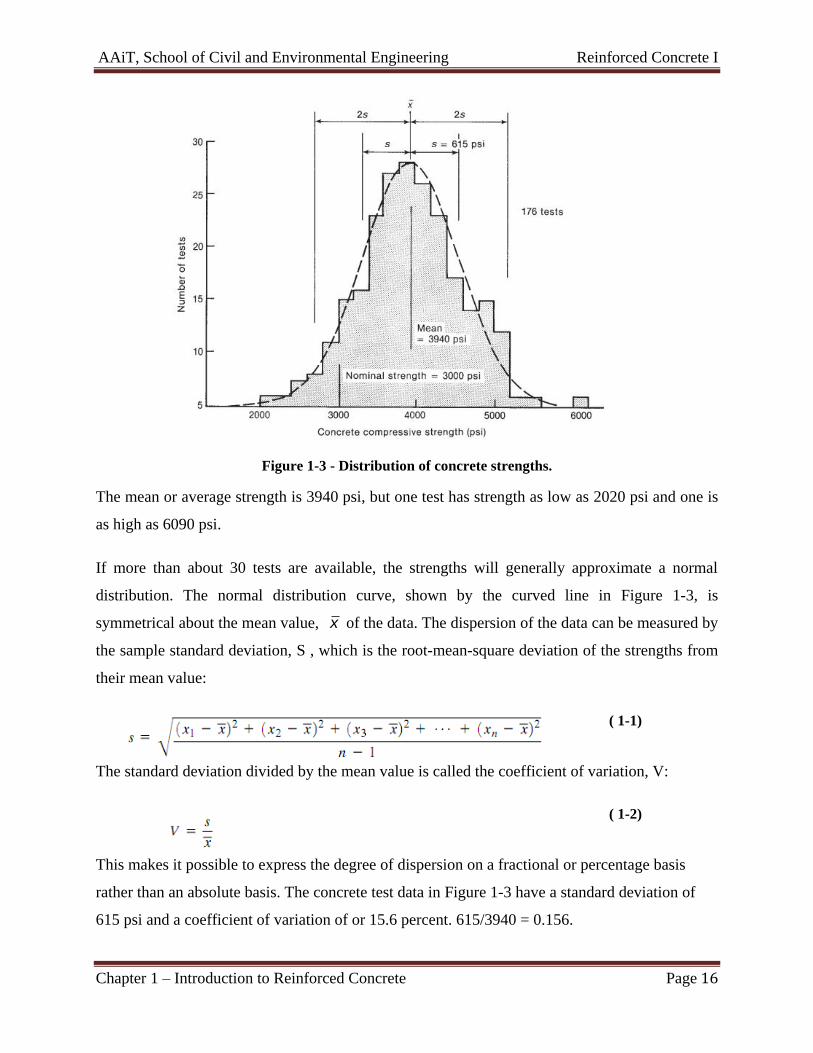
discrepancies in the tests will lead to apparent differences in strength. The shaded area in Figure
1-3 shows the distribution of the strengths in a sample of 176 concrete-strength tests.
AAiT, School of Civil and Environmental Engineering Reinforced Concrete I
Chapter 1 – Introduction to Reinforced Concrete Page 16
Figure 1-3 - Distribution of concrete strengths.
The mean or average strength is 3940 psi, but one test has strength as low as 2020 psi and one is
as high as 6090 psi.
If more than about 30 tests are available, the strengths will generally approximate a normal
distribution. The normal distribution curve, shown by the curved line in Figure 1-3, is
symmetrical about the mean value, x of the data. The dispersion of the data can be measured by
the sample standard deviation, S , which is the root-mean-square deviation of the strengths from
their mean value:
( 1-1)
The standard deviation divided by the mean value is called the coefficient of variation, V:
( 1-2)
This makes it possible to express the degree of dispersion on a fractional or percentage basis
rather than an absolute basis. The concrete test data in Figure 1-3 have a standard deviation of
615 psi and a coefficient of variation of or 15.6 percent. 615/3940 = 0.156.
AAiT, School of Civil and Environmental Engineering Reinforced Concrete I
Chapter 1 – Introduction to Reinforced Concrete Page 17
If the data correspond to a normal distribution, their distribution can be predicted from the
properties of such a curve. Thus, 68.3 percent of the data will lie within 1 standard deviation
above or below the mean. Alternatively, 15.6 percent of the data will have values less than
x s Similarly, for a normal distribution, 10 percent of the data, or 1 test in10, will have
values less than ̅(1-aV), where a=1.282, Values of a corresponding to other probabilities can
be found in statistics texts.
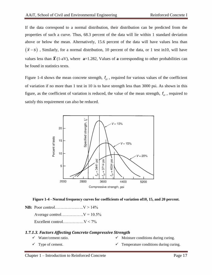
Figure 1-4 shows the mean concrete strength, crf , required for various values of the coefficient
of variation if no more than 1 test in 10 is to have strength less than 3000 psi. As shown in this
figure, as the coefficient of variation is reduced, the value of the mean strength, crf , required to
satisfy this requirement can also be reduced.
Figure 1-4 - Normal frequency curves for coefficients of variation of10, 15, and 20 percent.
NB: Poor control…………….…..V > 14%
Average control…………….V = 10.5%
Excellent control……………V < 7%
1.7.1.3. Factors Affecting Concrete Compressive Strength Water/cement ratio. Moisture conditions during curing.
Type of cement. Temperature conditions during curing.
AAiT, School of Civil and Environmental Engineering Reinforced Concrete I
Chapter 1 – Introduction to Reinforced Concrete Page 18
Supplementary cementitious materials. Age of concrete
Aggregate. Maturity of concrete
Mixing water. Rate of loading.
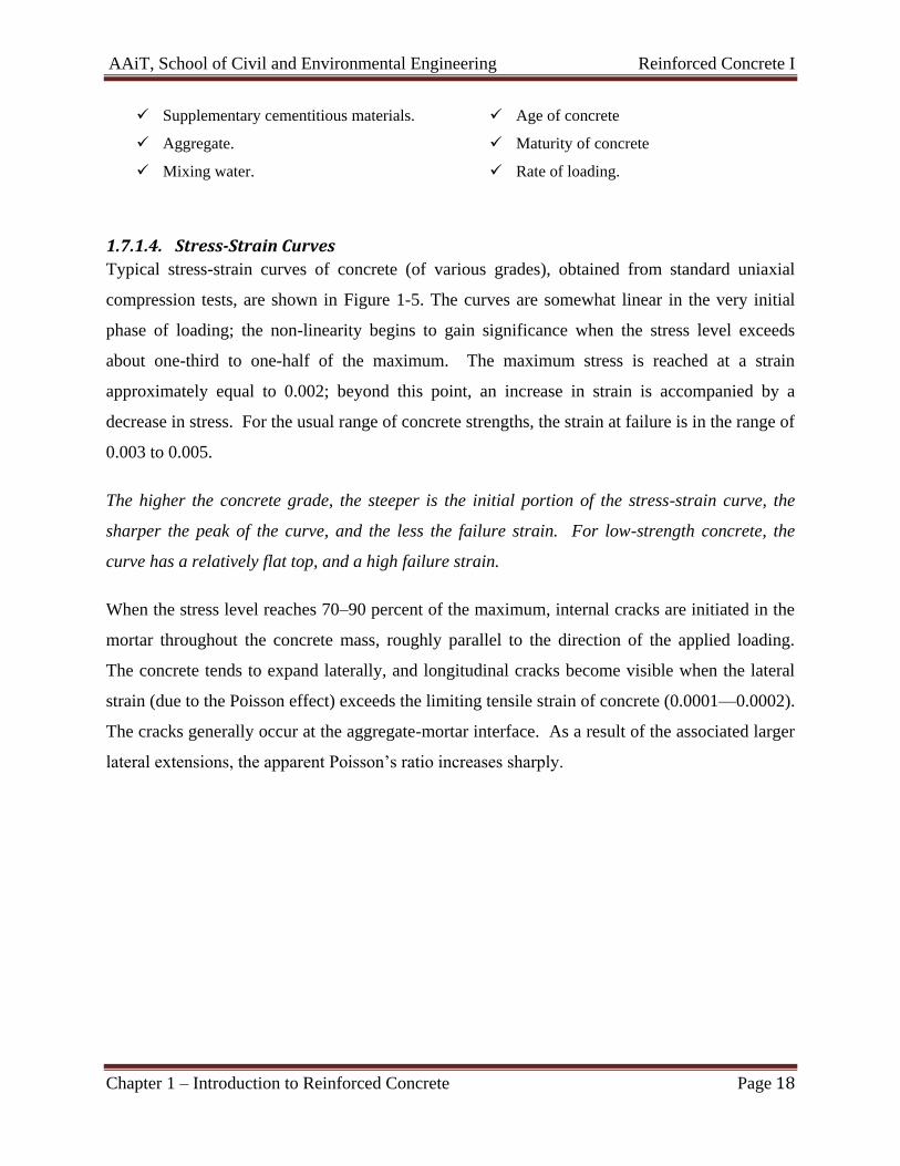
1.7.1.4. Stress-Strain Curves
Typical stress-strain curves of concrete (of various grades), obtained from standard uniaxial
compression tests, are shown in Figure 1-5. The curves are somewhat linear in the very initial
phase of loading; the non-linearity begins to gain significance when the stress level exceeds
about one-third to one-half of the maximum. The maximum stress is reached at a strain
approximately equal to 0.002; beyond this point, an increase in strain is accompanied by a
decrease in stress. For the usual range of concrete strengths, the strain at failure is in the range of
0.003 to 0.005.
The higher the concrete grade, the steeper is the initial portion of the stress-strain curve, the
sharper the peak of the curve, and the less the failure strain. For low-strength concrete, the
curve has a relatively flat top, and a high failure strain.
When the stress level reaches 70–90 percent of the maximum, internal cracks are initiated in the
mortar throughout the concrete mass, roughly parallel to the direction of the applied loading.
The concrete tends to expand laterally, and longitudinal cracks become visible when the lateral
strain (due to the Poisson effect) exceeds the limiting tensile strain of concrete (0.0001—0.0002).
The cracks generally occur at the aggregate-mortar interface. As a result of the associated larger
lateral extensions, the apparent Poisson’s ratio increases sharply.
AAiT, School of Civil and Environmental Engineering Reinforced Concrete I
Chapter 1 – Introduction to Reinforced Concrete Page 19
Figure 1-5 - Typical stress-strain curves of concrete in compression
The descending branch of the stress-strain curve can be fully traced only if the strain-controlled
application of the load is properly achieved. For this, the testing machine must be sufficiently
rigid (i.e., it must have a very high value of load per unit deformation); otherwise, the concrete is
likely to fail abruptly (sometimes, explosively) almost immediately after the maximum stress is
reached. The fall in stress with increasing strain is a phenomenon which is not clearly
understood; it is associated with extensive micro-cracking in the mortar, and is sometimes called
softening of concrete.
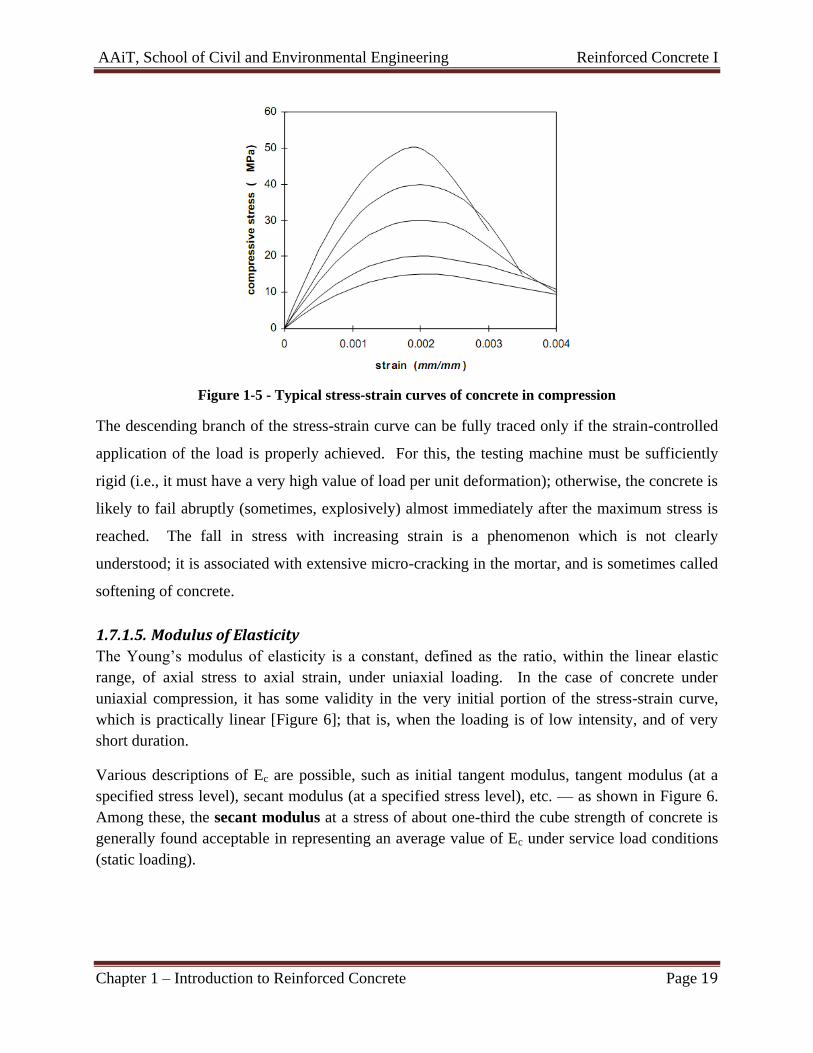
1.7.1.5. Modulus of Elasticity
The Young’s modulus of elasticity is a constant, defined as the ratio, within the linear elastic
range, of axial stress to axial strain, under uniaxial loading. In the case of concrete under
uniaxial compression, it has some validity in the very initial portion of the stress-strain curve,
which is practically linear [Figure 6]; that is, when the loading is of low intensity, and of very
short duration.
Various descriptions of Ec are possible, such as initial tangent modulus, tangent modulus (at a
specified stress level), secant modulus (at a specified stress level), etc. — as shown in Figure 6.
Among these, the secant modulus at a stress of about one-third the cube strength of concrete is
generally found acceptable in representing an average value of Ec under service load conditions
(static loading).
AAiT, School of Civil and Environmental Engineering Reinforced Concrete I
Chapter 1 – Introduction to Reinforced Concrete Page 20
Figure 6 – Various descriptions of modulus of elasticity of concrete
( I T≡ initial tangent, T ≡ tangent, S ≡ secant )
1.7.2. BEHAVIOR OF CONCRETE UNDER TENSION
Concrete is not normally designed to resist direct tension. However, tensile stresses do develop
in concrete members as a result of flexure, shrinkage and temperature changes. Principal
tensile stresses may also result from multi-axial states of stress. Often cracking in concrete is a
result of the tensile strength (or limiting tensile strain) being exceeded. As pure shear causes
tension on diagonal planes, knowledge of the direct tensile strength of concrete is useful for
estimating the shear strength of beams with unreinforced webs, etc. Also, knowledge of the
flexural tensile strength of concrete is necessary for estimation of the ‘moment at first crack’,
required for the computation of deflections and crack widths in flexural members.
As pointed out earlier, concrete is very weak in tension, the direct tensile strength being only
about 7 to 15 percent of the compressive strength. It is difficult to perform a direct tension test
on a concrete specimen, as it requires a purely axial tensile force to be applied, free of any
AAiT, School of Civil and Environmental Engineering Reinforced Concrete I
Chapter 1 – Introduction to Reinforced Concrete Page 21
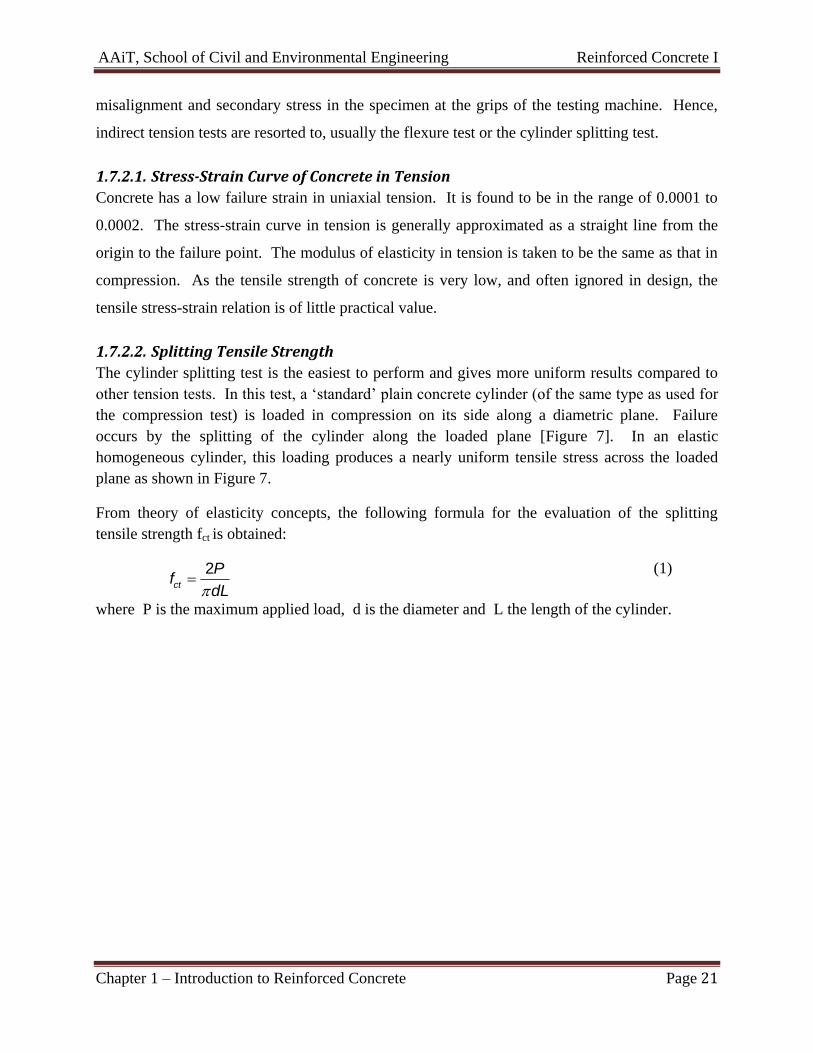
misalignment and secondary stress in the specimen at the grips of the testing machine. Hence,
indirect tension tests are resorted to, usually the flexure test or the cylinder splitting test.
1.7.2.1. Stress-Strain Curve of Concrete in Tension
Concrete has a low failure strain in uniaxial tension. It is found to be in the range of 0.0001 to
0.0002. The stress-strain curve in tension is generally approximated as a straight line from the
origin to the failure point. The modulus of elasticity in tension is taken to be the same as that in
compression. As the tensile strength of concrete is very low, and often ignored in design, the
tensile stress-strain relation is of little practical value.
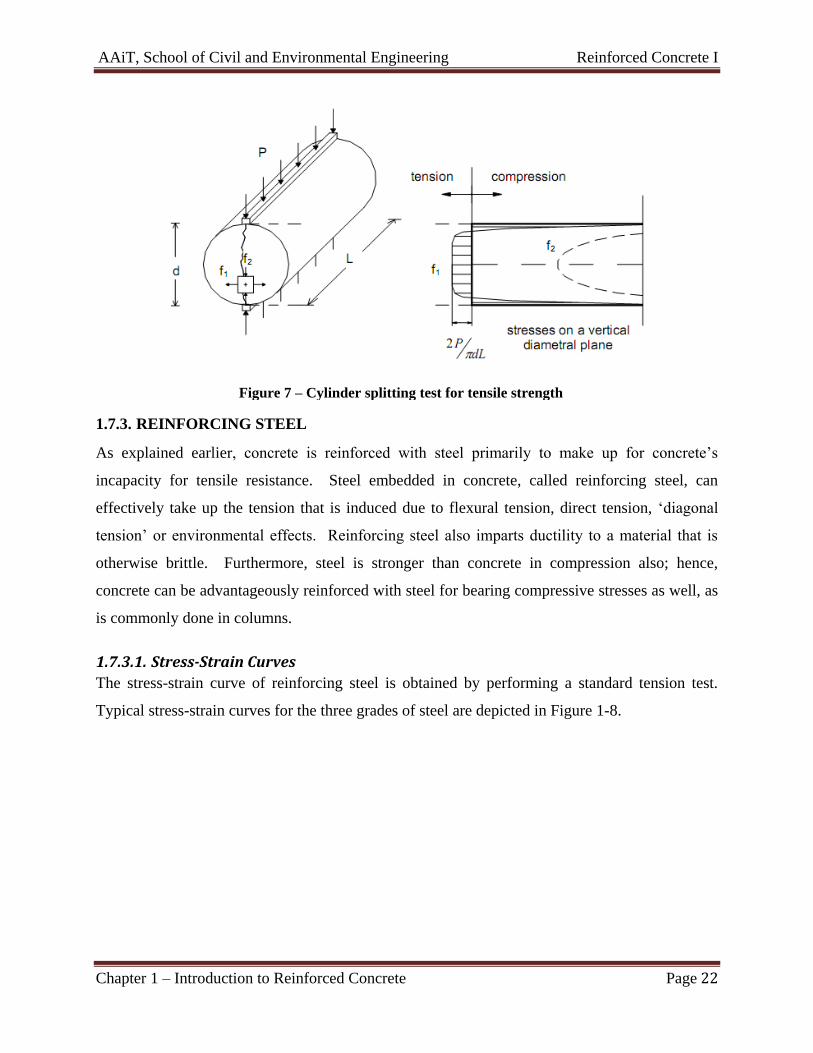
1.7.2.2. Splitting Tensile Strength
The cylinder splitting test is the easiest to perform and gives more uniform results compared to
other tension tests. In this test, a ‘standard’ plain concrete cylinder (of the same type as used for
the compression test) is loaded in compression on its side along a diametric plane. Failure
occurs by the splitting of the cylinder along the loaded plane [Figure 7]. In an elastic
homogeneous cylinder, this loading produces a nearly uniform tensile stress across the loaded
plane as shown in Figure 7.
From theory of elasticity concepts, the following formula for the evaluation of the splitting
tensile strength fct is obtained:
2ct
Pf
dL
(1)
where P is the maximum applied load, d is the diameter and L the length of the cylinder.
AAiT, School of Civil and Environmental Engineering Reinforced Concrete I
Chapter 1 – Introduction to Reinforced Concrete Page 22
Figure 7 – Cylinder splitting test for tensile strength
1.7.3. REINFORCING STEEL
As explained earlier, concrete is reinforced with steel primarily to make up for concrete’s
incapacity for tensile resistance. Steel embedded in concrete, called reinforcing steel, can
effectively take up the tension that is induced due to flexural tension, direct tension, ‘diagonal
tension’ or environmental effects. Reinforcing steel also imparts ductility to a material that is
otherwise brittle. Furthermore, steel is stronger than concrete in compression also; hence,
concrete can be advantageously reinforced with steel for bearing compressive stresses as well, as
is commonly done in columns.
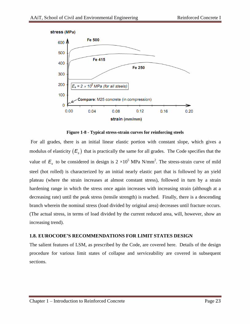
1.7.3.1. Stress-Strain Curves
The stress-strain curve of reinforcing steel is obtained by performing a standard tension test.
Typical stress-strain curves for the three grades of steel are depicted in Figure 1-8.
AAiT, School of Civil and Environmental Engineering Reinforced Concrete I
Chapter 1 – Introduction to Reinforced Concrete Page 23
Figure 1-8 - Typical stress-strain curves for reinforcing steels
For all grades, there is an initial linear elastic portion with constant slope, which gives a
modulus of elasticity sE that is practically the same for all grades. The Code specifies that the
value of sE to be considered in design is 2 ×10⁵ MPa N/mm
2. The stress-strain curve of mild
steel (hot rolled) is characterized by an initial nearly elastic part that is followed by an yield
plateau (where the strain increases at almost constant stress), followed in turn by a strain
hardening range in which the stress once again increases with increasing strain (although at a
decreasing rate) until the peak stress (tensile strength) is reached. Finally, there is a descending
branch wherein the nominal stress (load divided by original area) decreases until fracture occurs.
(The actual stress, in terms of load divided by the current reduced area, will, however, show an
increasing trend).
1.8. EUROCODE’S RECOMMENDATIONS FOR LIMIT STATES DESIGN
The salient features of LSM, as prescribed by the Code, are covered here. Details of the design
procedure for various limit states of collapse and serviceability are covered in subsequent
sections.
AAiT, School of Civil and Environmental Engineering Reinforced Concrete I
Chapter 1 – Introduction to Reinforced Concrete Page 24
1.8.1. ACTIONS
The term action is used in the Eurocodes in order to group together generically all external
influences on a structure’s performance. It encompasses loading by gravity and wind, but
includes also vibration, thermal effects, fire and seismic loading.
Separate combinations of actions are used to check the structure for the design situation being
considered. For each of the particular design situations an appropriate representative value for
each action is used.
1.8.1.1. Representative values of actions
The main actions to be used in load cases used for design are:
Permanent actions G: e.g. self-weight of structures and fixed equipment;
Variable actions Q: e.g. imposed loads on building floors and beams; snow loads on
roofs; wind loading on walls and roofs
Accidental actions A: e.g. fire, explosions and impact.
1.8.1.2. Permanent actions
The characteristic value of a permanent action kG may be a single value if variability is known
to be low (e.g. the self-weight of quality-controlled factory-produced members). If the variability
of G cannot be considered as small, and its magnitude may vary from place to place in the
structure, then an upper value ,supkG and a lower value
,infkG may occasionally be used.
1.8.1.3. Variable actions
Up to four types of representative value may be needed for the variable and accidental actions.
The types most commonly used for variable actions are:
The characteristic value kQ
and combinations of the characteristic value with other variable actions, multiplied by
different combination factors:
The combination value 0 kQ
The frequent value 1 kQ
The quasi-permanent value 2 kQ
Explanations of the representative values and the design situations in which they arise are given
below. The ‘ x ’ factors generally reduce the value of a variable action present in an accidental
situation compared with the characteristic value.
A. Combination value of 0 kQ
The combination value is used for checking:
1. Ultimate limit states;
AAiT, School of Civil and Environmental Engineering Reinforced Concrete I
Chapter 1 – Introduction to Reinforced Concrete Page 25
2. Irreversible serviceability limit states (e.g. deflections which fracture brittle fittings or
finishes).
It is associated with combinations of actions. The combination factor 0 reduces
kQ because of
the low probability of the most unfavourable values of several independent actions occurring
simultaneously.
B. Frequent value 1 kQ
The frequent value is used for checking:
1. Ultimate limit states involving accidental actions;
2. Reversible serviceability limit states, primarily associated with frequent combinations.
In both cases the reduction factor 1 multiplies the leading variable action. The frequent value
1 kQ of a variable action Q is determined so that the total proportion of a chosen period of time
during which Q exceeds 1 kQ is less than a specified small part of the period.
C. Quasi-permanent value 2 kQ
The quasi-permanent value is used for checking:
1. Ultimate limit states involving accidental actions;
2. Reversible serviceability limit states.
Quasi-permanent values are also used for the calculation of long-term effects (e.g. cosmetic
cracking of a slab) and to represent combinations of variable seismic actions. The quasi-
permanent value 2 kQ is defined so that the total proportion of a chosen period of time during
which Q exceeds 2 kQ is a considerable part (more than half) of the chosen period.
1.8.1.4. Load combinations for design
The values of actions to be used in design are governed by a number of factors. These include:
1. The nature of the load. Whether the action is permanent, variable or accidental, as the
confidence in the description of each will vary.
2. The limit state being considered. Clearly, the value of an action governing design must be
higher for the ultimate limit state than for serviceability for persistent and transient design
situations. Further, under serviceability conditions, loads vary with time, and the design
load to be considered could vary substantially. Realistic serviceability loads should be
modeled appropriate to the aspect of the behavior being checked (e.g. deflection, cracking
or settlement). For example, creep and settlement are functions of permanent loads only.
3. The number of variable loads acting simultaneously. Statistically, it is improbable that all
loads will act at their full characteristic value at the same time. To allow for this, the
characteristic values of actions will need modification.
AAiT, School of Civil and Environmental Engineering Reinforced Concrete I
Chapter 1 – Introduction to Reinforced Concrete Page 26
Consider the case of permanent action kG and one variable action kQ only. For the ultimate
limit state the characteristic values should be magnified, and the load may be represented as
G k Q kG Q , where the factors are the partial safety factors. The values of G and Q will be
different, and will be a reflection of the variabilities of the two loads being different. The gamma
factors account for:
1) The possibility of unfavourable deviation of the loads from the characteristic values
2) Inaccuracies in the analyses
3) Unforeseen redistribution of stress
4) Variations in the geometry of the structure and its elements, as this affects the
determination of the action effects.
Now consider the case of a structure subject to variable actions 1Q and 2Q simultaneously. If 1Q
and 2Q are independent, i.e. the occurrence and magnitude of 1Q does not depend on the
occurrence and magnitude of 2Q and vice versa, then it would be unrealistic to use
,1 ,1 ,2 ,2Q k Q kQ Q as the two loads are unlikely to act at their maximum at the same time. Joint
probabilities will need to be considered to ensure that the probability of occurrence of the two
loads is the same as that of a single load. It will be more reasonable to consider one load at its
maximum in conjunction with a reduced value for the other load. Thus, we have two
possibilities:
,1 ,1 0,2 ,2 ,2Q k Q kQ Q (2)
Or
0,1 ,1 ,1 ,2 ,2Q k Q kQ Q (3)
Multiplication by 0 is said to produce a combination value of the load. It should be noted that
the values of and 0 vary with each load.
The above discussion illustrates the thinking behind the method of combining loads for an
ultimate limit state check. Similar logic is applied to the estimation of loads for the different
serviceability checks.
I. Ultimate limit state
The following ultimate limit states shall be verified as relevant:
a) EQU: Loss of static equilibrium of the structure or any part of it considered as a rigid
body, where:
Minor variations in the value or the spatial distribution of actions from a single
source are significant, and
The strengths of construction materials or ground are generally not governing;
AAiT, School of Civil and Environmental Engineering Reinforced Concrete I
Chapter 1 – Introduction to Reinforced Concrete Page 27
b) STR: Internal failure or excessive deformation of the structure or structural members,
including footings, piles, basement walls, etc., where the strength of construction
materials of the structure governs;
c) GEO: Failure or excessive deformation of the ground where the strengths of soil or rock
are significant in providing resistance;
d) FAT: Fatigue failure of the structure or structural members.
Combinations of actions
1) Persistent and transient situations – fundamental combinations.
In the following paragraphs, various generalized combinations of loads are expressed
symbolically. It should be noted that the ‘+’ symbol in the expressions does not have the normal
mathematical meaning, as the directions of loads could be different. It is best to read it as
meaning ‘combined with’.
EN 1990 gives three separate sets of load combinations, namely EQU (to check against loss of
equilibrium), STR (internal failure of the structure governed by the strength of the construction
materials) and GEO (failure of the ground, where the strength of soil provides the significant
resistance).
Equilibrium: Equilibrium is verified using the load combination Set A in the code, which is as
follows:
, , ,1 ,1 , 0, ,G J k j Q k Q i i k iG Q Q (4)
, ,sup , ,supG j k jG is used when the permanent loads are unfavourable, and , ,inf , ,infG j k jG is used when
the permanent actions are favourable. Numerically, , ,sup 1.1G j ,
, ,inf 0.9G j , and 1.5Q
when unfavourable and 0 when favourable.
The above format applies to the verification of the structure as a rigid body (e.g. overturning of
retaining walls). A separate verification of the limit state of rupture of structural elements should
normally be undertaken using the format given below for strength. In cases where the
verification of equilibrium also involves the resistance of the structural member (e.g.
overhanging cantilevers), the strength verification given below without the above equilibrium
check may be adopted. In such verifications, , ,inf 1.15G j should be used.
Strength: when a design does not involve geotechnical actions, the strength of elements should
be verified using load combination Set B. two options are given. Either combination (6.10) from
EN 1990 or the less favourable of equations (6.10a) and (6.10b) may be used:
, , ,1 ,1 , 0, ,G j k j Q k Q i i k iG Q Q (5)

AAiT, School of Civil and Environmental Engineering Reinforced Concrete I
Chapter 1 – Introduction to Reinforced Concrete Page 28
, ,sup , ,supG j k jG is used when the permanent loads are unfavourable , and , ,inf , ,infG j k jG is used when
the permanent actions are favourable. Numerically, , ,sup 1.35G j ,
, ,inf 1.0G j , and 1.5Q
when unfavourable and 0 when favourable (EN1990)
, , , 0, ,G j k j Q i i k iG Q (6)
, , ,1 ,1 , 0, ,G j k j Q k Q i i k iG Q Q (7)
Numerically, , ,sup , ,inf0.925, 1.35, 1.0G j G j and 1.5Q when unfavourable and 0 when
favourable (EN 1990)
The above combinations assume that a number of variable actions are present at the same time.
,1kQ is the dominant load if it is obvious, otherwise each load is in turn treated as a dominant
load and the other as secondary. The dominant load is then combined with the combination value
of the secondary loads. Both are multiplied by their respective values.
The magnitude of the load resulting from equations (6.10a) and (6.10b) will always be less than
that from equation (6.10).
Now turning to the factors ,infG and
,supG , it will be noted that the numerical values are
different in the verification of equilibrium and that of strength. For instance, in an overhanging
cantilever beam, the multiplier for self-weight in the cantilever section will be ,sup1.1 G and
that in the anchor span will be ,0.9 G cnf . The possible explanation for ,supG being 1.1 and not
1.35 as in the strength check is that
a) The variability in self-weight of the element is unlikely to be large
b) The factor 1.35 has built into it an allowance for structural performance (which is
necessary only for strength checks)
c) The loading in the cantilever will also generally include variable actions, partial safety
factors for which will ensure a reasonable overall safety factor.
When a design involves geotechnical action, a number of approaches are given in EN 1990, and
the choice of the method is a Nationally Determined Parameter.
2) Accidental design situation
The load combination recommended is
, 1, ,1 2, ,k j d i k i k iG A Q Q (8)
where dA is the design value of accidental action, ,1kQ is the main variable action accompanying
the accidental action and ,k iQ are other variable actions.
Accidents are unintended events such as explosions, fire or vehicular impact, which are of short
duration and which have a low probability of occurrence. Also, a degree of damage is generally
AAiT, School of Civil and Environmental Engineering Reinforced Concrete I
Chapter 1 – Introduction to Reinforced Concrete Page 29
acceptable in the event of an accident. The loading model should attempt to describe the
magnitude of other variable loads which are likely to occur in conjunction with the accidental
load. Accidents generally occur in structures in use. Therefore, the values of variable actions will
be less than those used for the fundamental combination of loads in (1) above. To provide a
realistic variable load combining with the accidental load, the variable actions are multiplied by
different (and generally lower) factors. Multiplier 1 is applied to the dominant action, and
2 to the others. Where the dominant action is not obvious, each variable action present is in
turn treated as dominant. Q for accidental situations is unity.
Multiplication by 1 is said to produce a frequent value of the load, and multiplication by 2 the
quasi-permanent value. Numerical values for 1 and 2 are given in EN 1990.
3) Seismic design situations
, 2, ,1 1
k j Ed i k ij i
G A Q
(9)
II. Serviceability limit state
Combination of actions
1) Characteristic combination.
, ,1 0, ,1
k j k i k ii
G Q Q
(10)
This represents a combination of service loads, which can be considered rather infrequent. It
might be appropriate for checking sates such as micro cracking or possible local non-catastrophic
failure of reinforcement leading to large cracks in sections.
2) Frequent combination
, 1,1 ,1 2, , 1k j k i k iG Q Q i (11)
This represents a combination that is likely to occur relatively frequently in service conditions,
and is used for checking cracking.
3) Quasi-permanent combination
, 2, , 1k j i k iG Q i (12)
This will provide an estimate of sustained loads on the structure, and will be appropriate for the
verification of creep, settlement, etc.
It should be realized that the above combinations describe the magnitude of loads which are
likely to be present simultaneously. The actual arrangement of loads in position and direction
within the structure to create the most critical effect is a matter of structural analysis (e.g. loading
alternate or adjacent spans in continuous beams).
Values of factors
AAiT, School of Civil and Environmental Engineering Reinforced Concrete I
Chapter 1 – Introduction to Reinforced Concrete Page 30
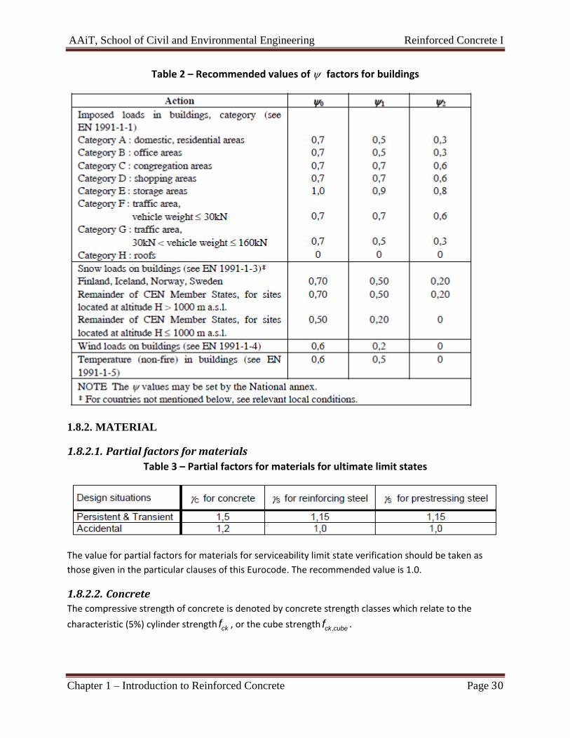
Table 2 – Recommended values of factors for buildings
1.8.2. MATERIAL
1.8.2.1. Partial factors for materials
Table 3 – Partial factors for materials for ultimate limit states
The value for partial factors for materials for serviceability limit state verification should be taken as
those given in the particular clauses of this Eurocode. The recommended value is 1.0.
1.8.2.2. Concrete
The compressive strength of concrete is denoted by concrete strength classes which relate to the
characteristic (5%) cylinder strength ckf , or the cube strength,ck cubef .
AAiT, School of Civil and Environmental Engineering Reinforced Concrete I
Chapter 1 – Introduction to Reinforced Concrete Page 31
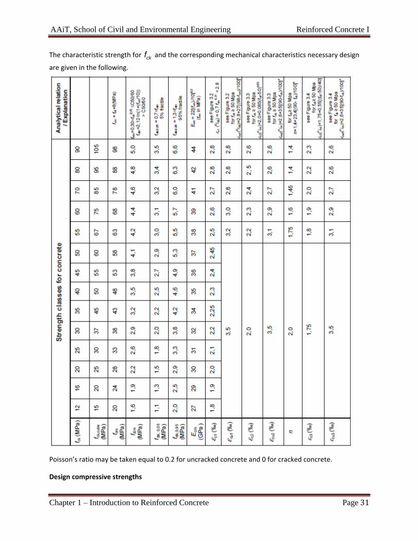
The characteristic strength for ckf and the corresponding mechanical characteristics necessary design
are given in the following.
Poisson’s ratio may be taken equal to 0.2 for uncracked concrete and 0 for cracked concrete.
Design compressive strengths
AAiT, School of Civil and Environmental Engineering Reinforced Concrete I
Chapter 1 – Introduction to Reinforced Concrete Page 32
The value of the design compressive strength is defined as
cd cc ck cf f (13)
Where:
c is the partial safety factor for concrete
cc is the coefficient taking account of long term effects on the compressive strength and of
unfavourable effects resulting from the way the load is applied.
The value of cc for use in a Country should lie between 0.8 and 1.0 and may be found in its National
Annex. The recommended value is 1.
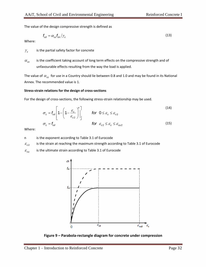
Stress-strain relations for the design of cross-sections
For the design of cross-sections, the following stress-strain relationship may be used.
2
2
1 1 0
n
cc cd c c
c
f for
(14)
2 2c cd c c cuf for (15)
Where:
n is the exponent according to Table 3.1 of Eurocode
2c is the strain at reaching the maximum strength according to Table 3.1 of Eurocode
cu is the ultimate strain according to Table 3.1 of Eurocode
Figure 9 – Parabola-rectangle diagram for concrete under compression
AAiT, School of Civil and Environmental Engineering Reinforced Concrete I
Chapter 1 – Introduction to Reinforced Concrete Page 33
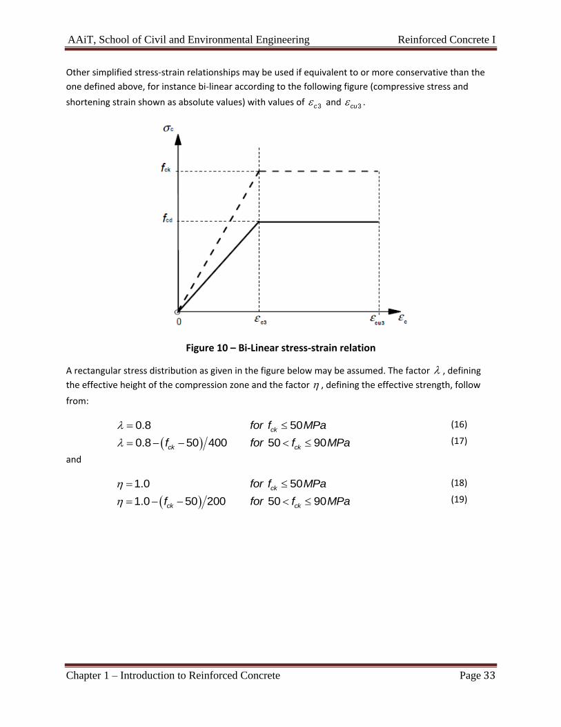
Other simplified stress-strain relationships may be used if equivalent to or more conservative than the
one defined above, for instance bi-linear according to the following figure (compressive stress and
shortening strain shown as absolute values) with values of 3c and 3cu .
Figure 10 – Bi-Linear stress-strain relation
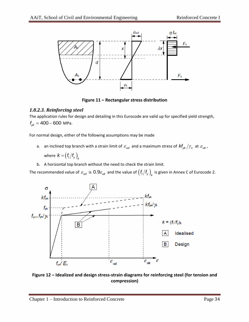
A rectangular stress distribution as given in the figure below may be assumed. The factor , defining
the effective height of the compression zone and the factor , defining the effective strength, follow
from:
0.8 50ckfor f MPa (16)
0.8 50 400 50 90ck ckf for f MPa (17)
and
1.0 50ckfor f MPa (18)
1.0 50 200 50 90ck ckf for f MPa (19)
AAiT, School of Civil and Environmental Engineering Reinforced Concrete I
Chapter 1 – Introduction to Reinforced Concrete Page 34
Figure 11 – Rectangular stress distribution
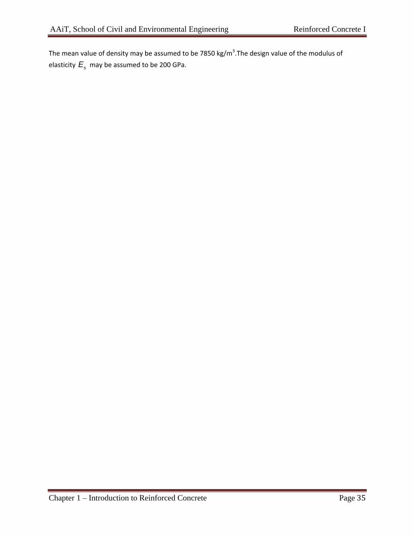
1.8.2.3. Reinforcing steel
The application rules for design and detailing in this Eurocode are valid up for specified yield strength,
400 600ykf MPa.
For normal design, either of the following assumptions may be made
a. an inclined top branch with a strain limit of ud and a maximum stress of yk skf at uk ,
where t y kk f f
b. A horizontal top branch without the need to check the strain limit.
The recommended value of ud is 0.9 uk and the value of t y kf f is given in Annex C of Eurocode 2.
Figure 12 – Idealized and design stress-strain diagrams for reinforcing steel (for tension and compression)
AAiT, School of Civil and Environmental Engineering Reinforced Concrete I
Chapter 1 – Introduction to Reinforced Concrete Page 35
The mean value of density may be assumed to be 7850 kg/m3.The design value of the modulus of
elasticity sE may be assumed to be 200 GPa.