Embed Size (px)
Citation preview
1
CHAPTER 1 Introduction of Control System
DR. SHAFISHUHAZA SAHLAN| DR. SHAHDAN SUDIN DR. HERMAN WAHID | DR. FATIMAH SHAM ISMAIL
Department of Control and Mechatronics Engineering
Faculty of Electrical Engineering Universiti Teknologi Malaysia
Content
• History of Control System 1.1
• Control System Basics 1.2
• Control System Configuration 1.3
• Examples of Control Systems 1.4
• Control System Design 1.5
• Simulation Software in Control – MATLAB 1.6
2
3
1.1 History of Control
System

History of Control System
4
Early • Simple, primitive
20th Century • Extensive use of sensors
Contemporary • Widespread applications
1900’s 2000’s 300 BC
• Water clock (300 BC) • Steam pressure &
temperature control systems (1680s)
• Speed control (1745) • Stability Theories
• Routh-‐Hurwitz (1877)
• Lyapunov (1892)
• AutomaNc Ship Steering (1922)
• PID Controller (1920s) • Feedback Control System
Technique (1930s) • Root locus, Bode, Nyquist
(1948)
• NavigaNon • Entertainment • Smart Homes • Military • Space ApplicaNon • Chemical Process
5
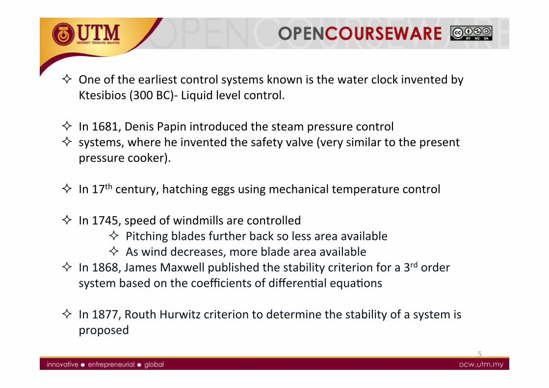
² One of the earliest control systems known is the water clock invented by Ktesibios (300 BC)-‐ Liquid level control.
² In 1681, Denis Papin introduced the steam pressure control ² systems, where he invented the safety valve (very similar to the present
pressure cooker).
² In 17th century, hatching eggs using mechanical temperature control
² In 1745, speed of windmills are controlled ² Pitching blades further back so less area available ² As wind decreases, more blade area available
² In 1868, James Maxwell published the stability criterion for a 3rd order system based on the coefficients of differenNal equaNons
² In 1877, Routh Hurwitz criterion to determine the stability of a system is proposed

6
1.2 Control System
Basics
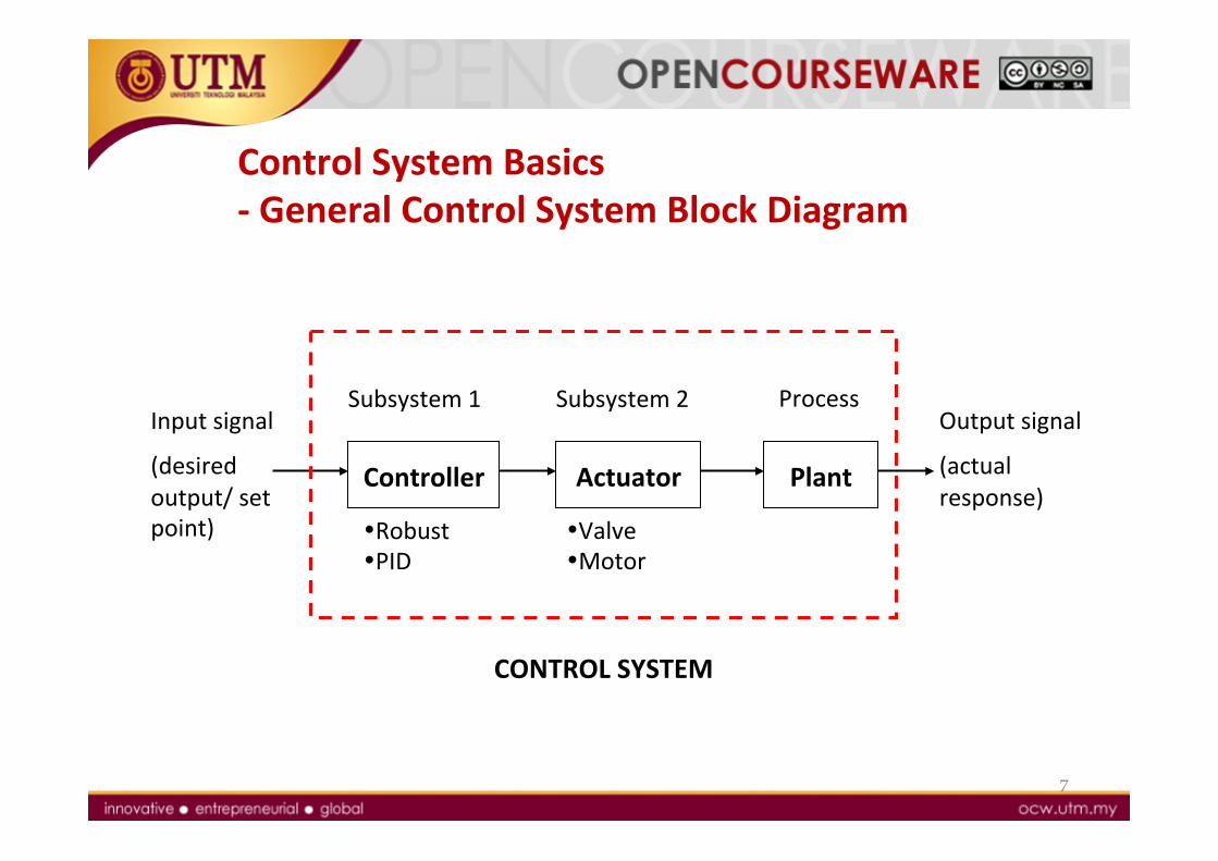
Control System Basics -‐ General Control System Block Diagram
7
Output signal
(actual response)
Controller Plant
Subsystem 1 Subsystem 2 Process
• Robust • PID
• Valve • Motor
CONTROL SYSTEM
Input signal
(desired output/ set point)
Actuator
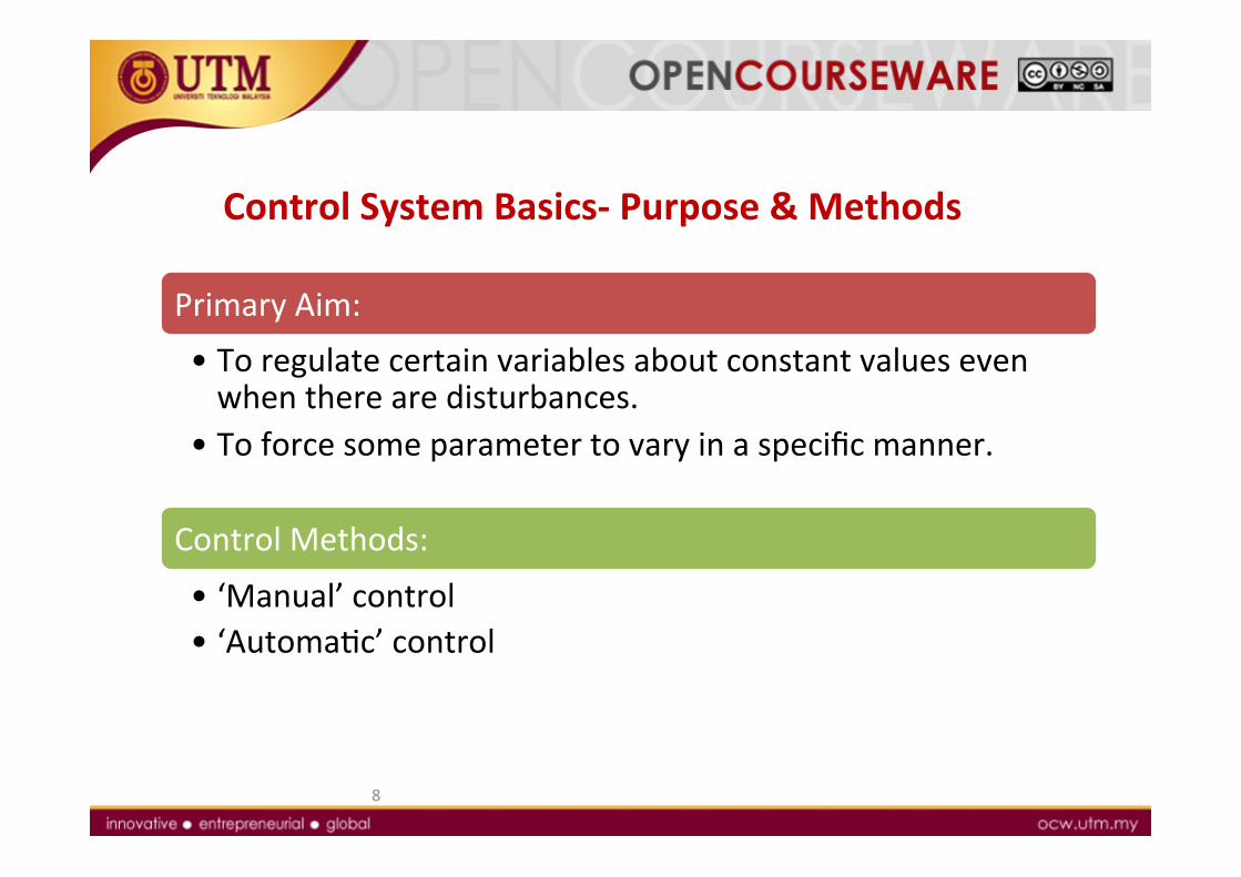
Control System Basics-‐ Purpose & Methods
Primary Aim: • To regulate certain variables about constant values even when there are disturbances.
• To force some parameter to vary in a specific manner.
Control Methods:
• ‘Manual’ control • ‘AutomaNc’ control
8
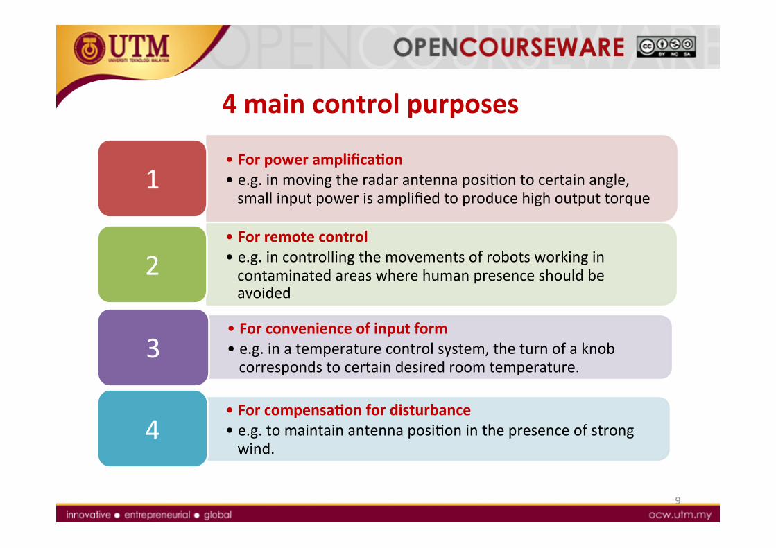
4 main control purposes
• For power amplificaQon • e.g. in moving the radar antenna posiNon to certain angle, small input power is amplified to produce high output torque
1
• For remote control • e.g. in controlling the movements of robots working in contaminated areas where human presence should be avoided
2
• For convenience of input form • e.g. in a temperature control system, the turn of a knob corresponds to certain desired room temperature.
3
• For compensaQon for disturbance • e.g. to maintain antenna posiNon in the presence of strong wind.
4
9

Manual Control
10
Human-‐aided control
Operator constantly observe the deviaNon and make correcNons when necessary
Not consistent
Hundreds of variables to be controlled
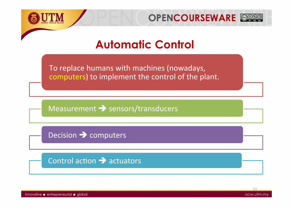
Automatic Control
To replace humans with machines (nowadays, computers) to implement the control of the plant.
Measurement è sensors/transducers
Decision è computers
Control acNon è actuators
11
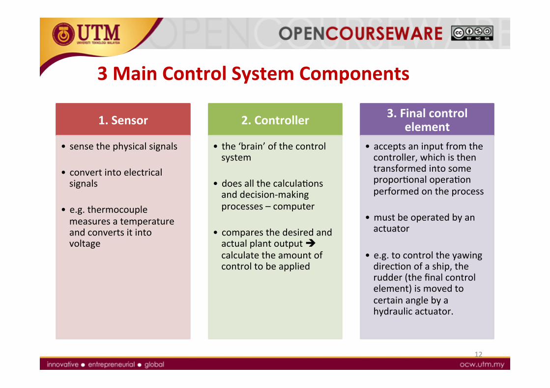
3 Main Control System Components
12
1. Sensor
• sense the physical signals
• convert into electrical signals
• e.g. thermocouple measures a temperature and converts it into voltage
2. Controller
• the ‘brain’ of the control system
• does all the calculaNons and decision-‐making processes – computer
• compares the desired and actual plant output è calculate the amount of control to be applied
3. Final control element
• accepts an input from the controller, which is then transformed into some proporNonal operaNon performed on the process
• must be operated by an actuator
• e.g. to control the yawing direcNon of a ship, the rudder (the final control element) is moved to certain angle by a hydraulic actuator.
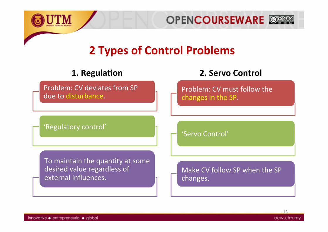
2 Types of Control Problems
13
Problem: CV deviates from SP due to disturbance.
‘Regulatory control’
To maintain the quanNty at some desired value regardless of external influences.
Problem: CV must follow the changes in the SP.
‘Servo Control’
Make CV follow SP when the SP changes.
1. RegulaQon 2. Servo Control
14
1.3 Control System
Configuration

Control System ConfiguraQon
15
Open-‐loop Closed-‐loop
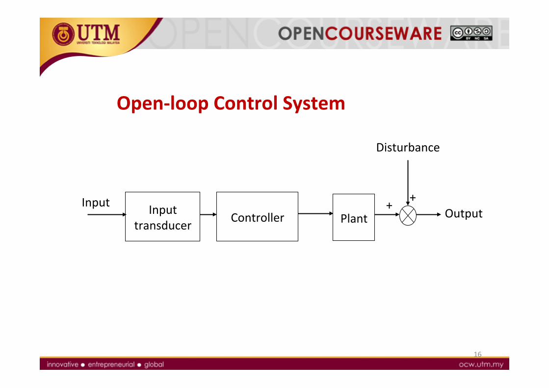
Open-‐loop Control System
16
Output Input transducer Controller Plant
Input
+ +
Disturbance
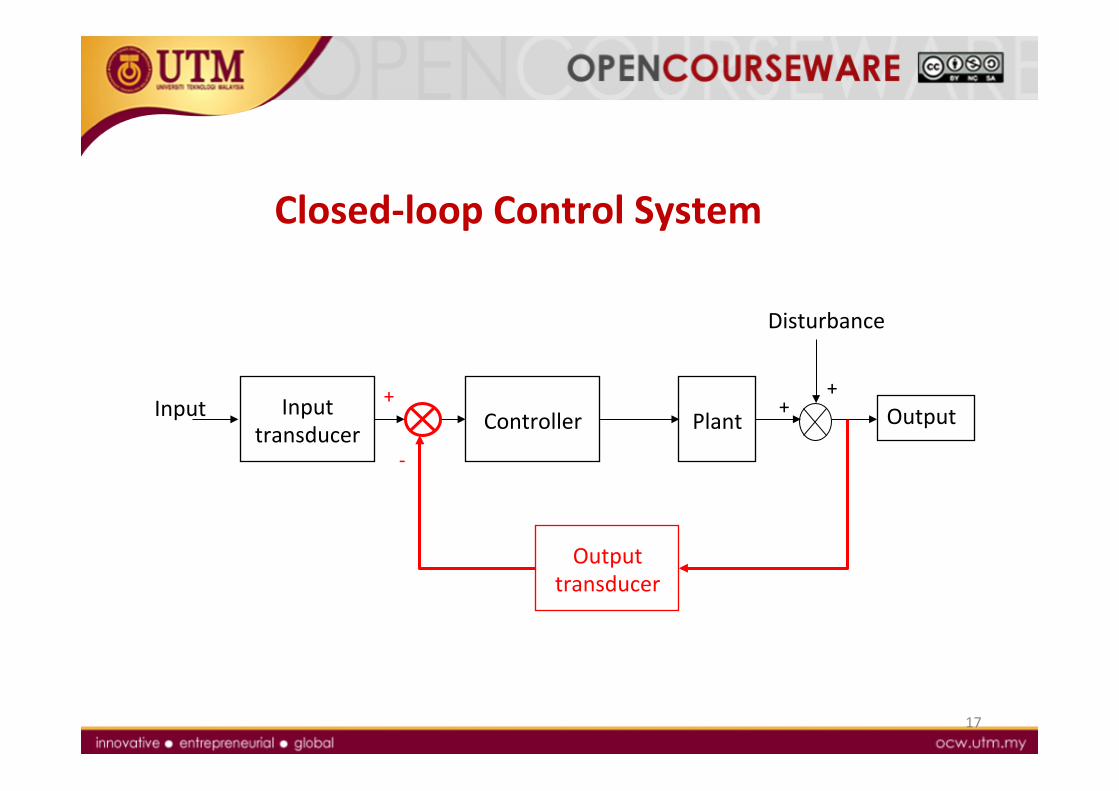
Closed-‐loop Control System
17
Output Input transducer Plant Input
+ +
Disturbance
+
-‐
Controller
Output transducer
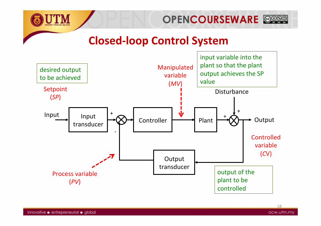
Closed-‐loop Control System
18
Output Input transducer Plant
Input
+
+
Disturbance
+
-‐
Controller
Output transducer
Process variable (PV)
Controlled variable (CV)
output of the plant to be controlled
Manipulated variable (MV)
input variable into the plant so that the plant output achieves the SP value
Setpoint (SP)
desired output to be achieved
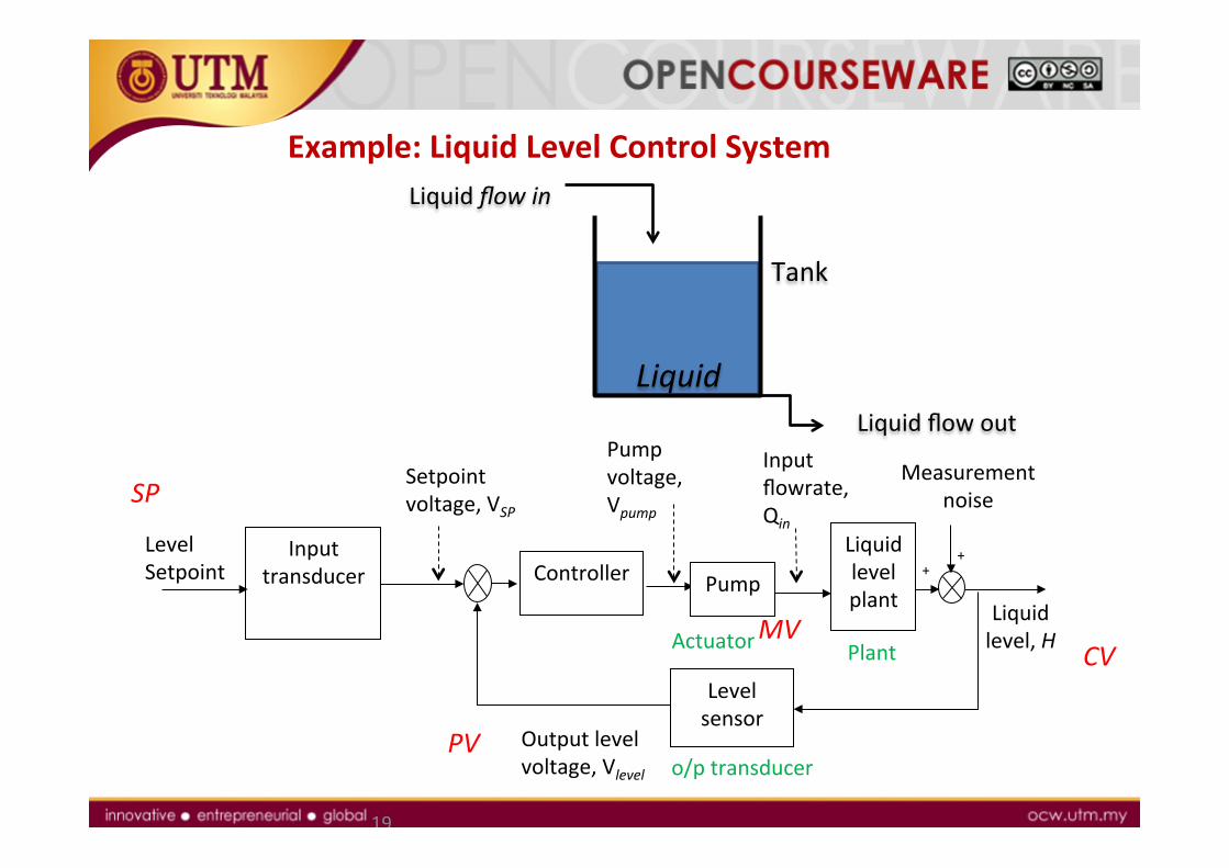
Example: Liquid Level Control System
19
Controller Liquid level plant
Level Setpoint + +
Level sensor
Setpoint voltage, VSP
Input transducer
Pump voltage, Vpump
Input flowrate, Qin
Output level voltage, Vlevel
Liquid level, H
Measurement noise
Pump
SP
PV
MV CV Actuator Plant
o/p transducer
Tank
Liquid
Liquid flow in
Liquid flow out
1.4 Examples of
Control Systems

Examples
21
Power amplificaNon in a dish-‐type antennas
• Varying in diameter from 8 to 30 metres
• Serving an Earth staNon in a satellite communicaNons network.
Remote control robots in contaminated area: Sojourner
• Roving on Mars in 1997. • Solar-‐powered, 11.5 kg. • Speed: 0.4 meters/minute • Its wheel system enabled it to climb over obstacles one-‐and-‐a-‐half wheel diameters tall.
Convenient input for a thermostat
• PosiNon to heat
Disturbance compensaNon in a Rolling Mill
• Maintain steel thickness despite variaNons/disturbance
1.5 Control System
Design
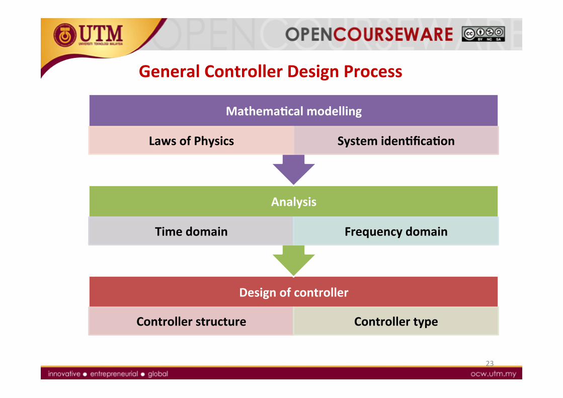
General Controller Design Process
23
Design of controller
Controller structure Controller type
Analysis
Time domain Frequency domain
MathemaQcal modelling
Laws of Physics System idenQficaQon
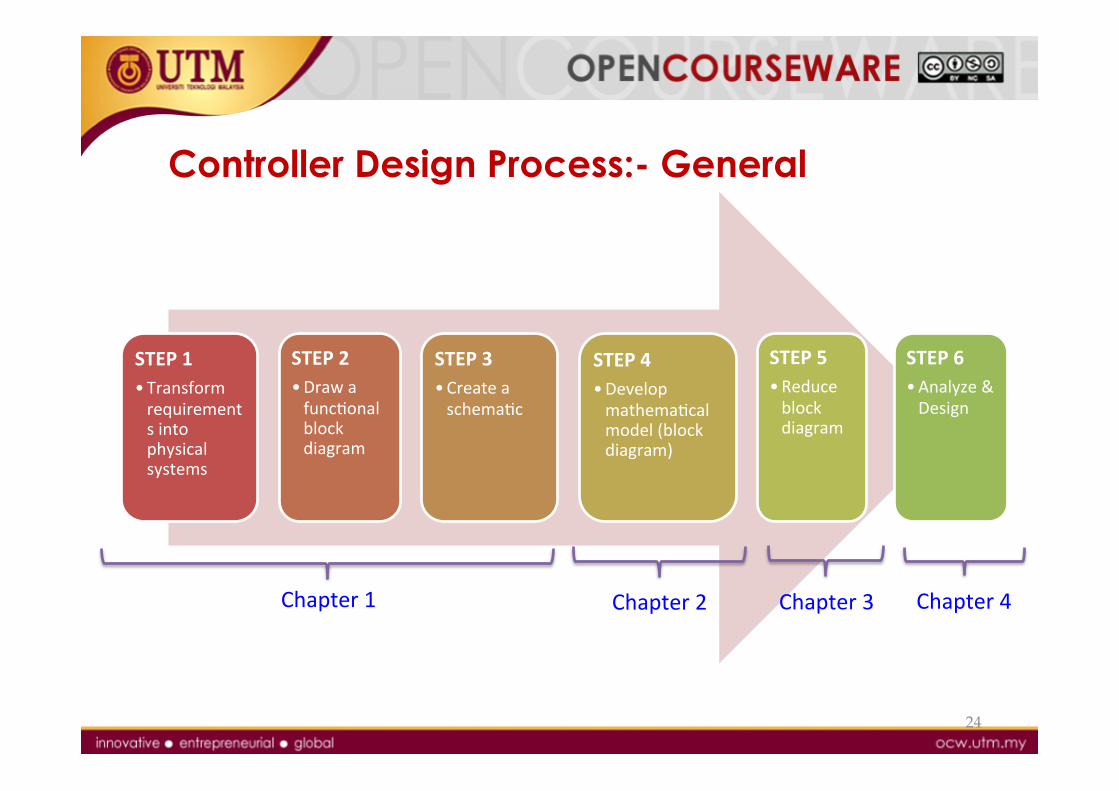
Controller Design Process:- General
STEP 1 • Transform requirements into physical systems
STEP 2 • Draw a funcNonal block diagram
STEP 3 • Create a schemaNc
STEP 4 • Develop mathemaNcal model (block diagram)
STEP 5 • Reduce block diagram
STEP 6 • Analyze & Design
24
Chapter 1 Chapter 2 Chapter 3 Chapter 4
25
1.6 Simulation Software in Control - MATLAB
MATLAB
• Important tool in current control system design.
• MATLAB contains: • Lots of Toolboxes – one of them is ‘Control System Toolbox’ • Simulink – click and drag
26
Control System Toolbox
• Contains a set of funcNons relaNon to control system design.
• Can be used together with other MATLAB funcNons or funcNons from other toolboxes.
27
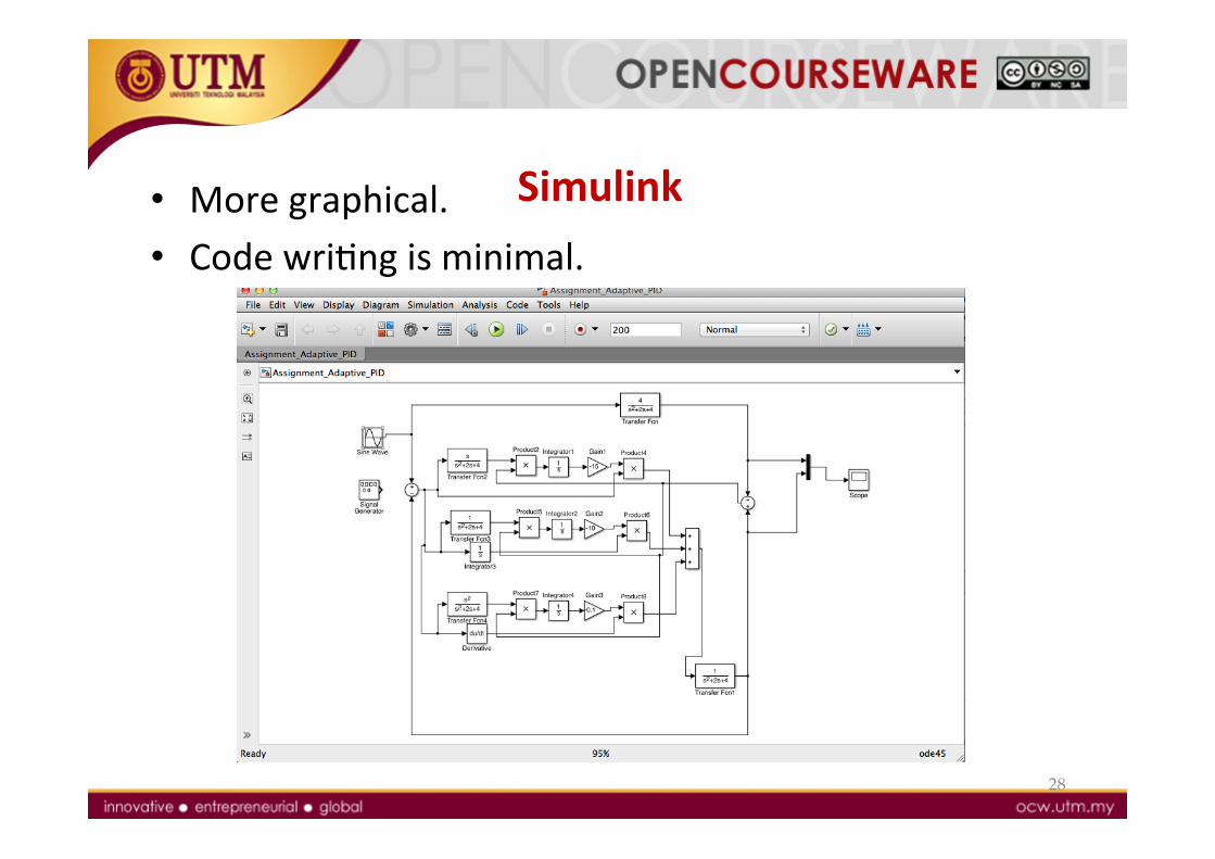
Simulink • More graphical. • Code wriNng is minimal.
28
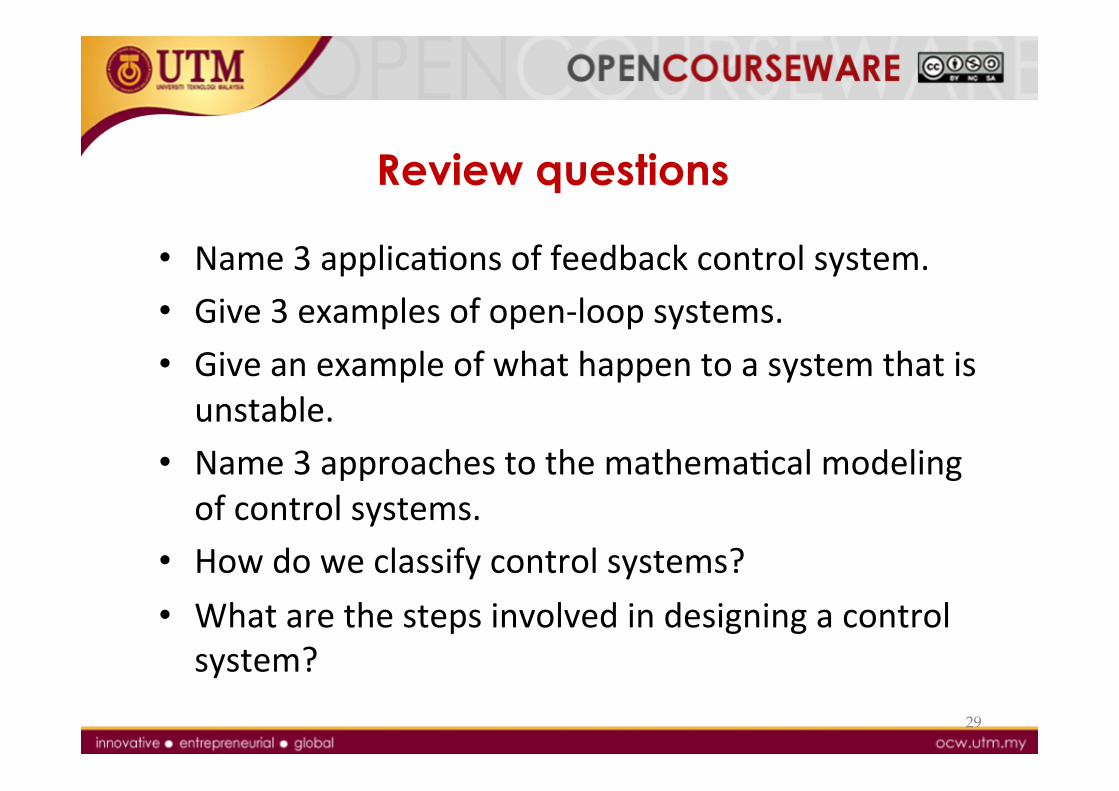
Review questions
• Name 3 applicaNons of feedback control system. • Give 3 examples of open-‐loop systems. • Give an example of what happen to a system that is unstable.
• Name 3 approaches to the mathemaNcal modeling of control systems.
• How do we classify control systems? • What are the steps involved in designing a control system?
29
30
REFERENCES [1] Norman S. Nise, Control Systems Engineering (6th EdiNon), John
Wiley and Sons, 2011. [2] Katsuhiko Ogata, Modern Control Engineering (5th EdiNon),
Pearson EducaNon InternaNonal, Inc., 2010. [3] Richard C. Dorf and Robert H. Bishop, Modern Control Systems
(12th EdiNon), Pearson EducaNonal InternaNonal, 2011. [4] Rao V. DukkipaN, Analysis and Design of Control systems Using
MATLAB, Published by New Age InternaNonal (P) Ltd., Publishers, 2006.
[5] Katsuhiko Ogata, MATLAB For Control Engineers, Pearson EducaNon InternaNonal, Inc., 2008.