Embed Size (px)
Citation preview

Chapter. 1 – Introduction DIN NANO FSC
USER AND MAINTENANCE MANUAL
Rev. 01-18 Page 1
REV. 01/04
User and maintenance manual
ENGLISH
ELECTRICAL BOARDS FOR REFRIGERATING INSTALLATIONS
READ AND KEEP
REV. 01-18 ENG
200NDINFSC Electronic regulator on din bar
to manage condenser fans

DIN NANO FSC Contents
USER AND MAINTENANCE MANUAL
Rev. 01-18 Page 2
INTRODUCTION
Page 3 1.1 General Page 3 1.2 Product identification codes Page 4 1.3 Overall dimensions Page 4 1.4 Identification data
INSTALLATION
Page 5 2.1 General rules for the installer Page 5 2.2 Standard equipment for assembly and use Page 6 2.3 Installation of the board
TECHNICAL FEATURES
Page 7 3.1 Technical features
TERMS OF THE GUARANTEE
Page 8 4.1 Terms of the guarantee
DATA PROGRAMMING
Page 9 5.1 Control panel Page 9 5.2 Front keypad Page 10 5.3 LED display Page 11 5.4 Combination of keys Page 12 5.5 Setting and viewing the set point Page 12 5.6 Level 1 programming Page 12 5.7 List of Level 1 variables Page 14 5.8 Level 2 programming Page 14 5.9 List of Level 2 variables Page 17 5.10 Level 3 programming Page 17 5.11 List of Level 3 variables Page 18 5.13 Operating mode Page 18 5.13.1 Normal mode Page 19 5.13.2 Energy saving mode Page 20 5.13.3 Low noise mode Page 21 5.13.4 Fixed speed mode Page 22 5.14 night / day function Page 22 5.15 Password function
OPTIONS
Page 23 6.1 TeleNET monitoring/supervision system Page 23 6.2 Network configuration with Modbus-RTU protocol
DIAGNOSTICS
Page 24 7.1 Diagnostics
ANNEXES
Page 25 A.1 CE Declaration of Conformity Page 26 A.2 Connection diagram
REV. 01/04
CHAP. 1
CHAP. 2
CHAP. 3
CHAP. 4
CHAP. 5
CHAP. 6
CHAP. 7
CONTENTS

Chapter. 1 – Introduction DIN NANO FSC
USER AND MAINTENANCE MANUAL
Rev. 01-18 Page 3
GENERAL INFORMATION
DESCRIPTION: The DIN NANO FSC is a DIN rail electronic regulator which optimizes the management of the condenser fans. It helps reduce energy consumption by regulating the condensation temperature according to the external temperature. It can also reduce the sound emissions from the condensing fans during the night, slowing down the fans if the external temperature drops. APPLICATIONS: - Control for electronic fans used on condensing units. - Control for phase-cutting voltage regulators used to manage the condensation fan
speed.
MAIN FEATURES. - 0-10 V analog output for speed control of the condenser fans - Regulation with pressure or temperature probe - Acquisition of outside temperature to optimize the control - 4 operating modes:
o normal mode. o energy saving o low noise of fans. o constant speed (adjustable).
- Night / day function (change of condensation setpoint). - View of the pressure transducer reading in Bar or in °C (depending on the type of
selected refrigerant gas). - 3-digit LED display with sign, decimal point and system status icons. - RS485 serial connection with Modbus-RTU or Telenet protocol. - PEGO programming criteria that guarantees immediate start-up. - Supply voltage 230Vac.
PRODUCT IDENTIFICATION CODES
200NDINFSC01 Electronic regulator on DIN bar for the optimized management of the fans of the condensing group
CHAPTER 1: INTRODUCTION
1.1
1.2
DIN NANO FSC Chapter 1 – Introduction
USER AND MAINTENANCE MANUAL
Rev. 01-18 Page 4
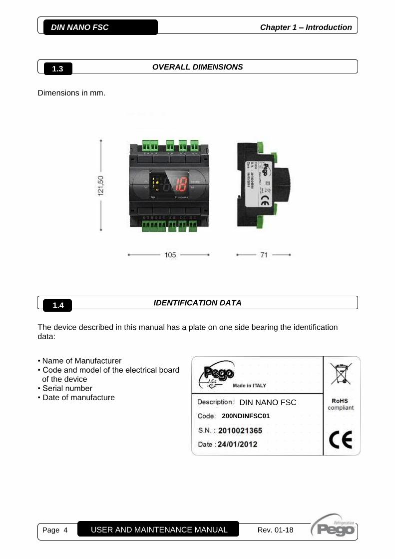
OVERALL DIMENSIONS
Dimensions in mm.
IDENTIFICATION DATA
The device described in this manual has a plate on one side bearing the identification data:
• Name of Manufacturer • Code and model of the electrical board of the device • Serial number • Date of manufacture
1.3
1.4
DIN NANO FSC
200NDINFSC01

Chapter 2 – Installation DIN NANO FSC
Page 5 USER AND MAINTENANCE MANUAL
Rev. 01-18
GENERAL RULES FOR THE INSTALLER 1. Install the device in an area that ensures the correct degree of protection, and take all
due care when drilling holes in the box for the cable glands and/or hoses; 2. Avoid using multi-pole cables with conductors connected to inductive and power
conductors and signal conductors like probes and digital inputs; 3. Avoid inserting ducts and power cables with signal cables (sensors and digital inputs) in
these. 4. Minimize the length of the connecting cables to prevent these from coiling up and
adversely affecting the electronics through induction; 5. All the conductors of the cables must be of an appropriate size to withstand the required
load; 6. When extensions are needed for the sensors, it is necessary to use conductors of a
suitable size measuring no less than 1 mm². Extension or shortening of the probes may alter the factory settings; use an external thermometer, therefore, for testing and calibration.
STANDARD EQUIPMENT FOR ASSEMBLY AND USE The DIN NANO FSC electronic controller is provided with the following for assembly and use: • 1 x user manual.
2.1
2.2
CHAPTER 2: INSTALLATION
DIN NANO FSC Chapter 2 – Installation
USER AND MAINTENANCE MANUAL
Rev. 01-18 Page 6
INSTALLATION OF BOARD
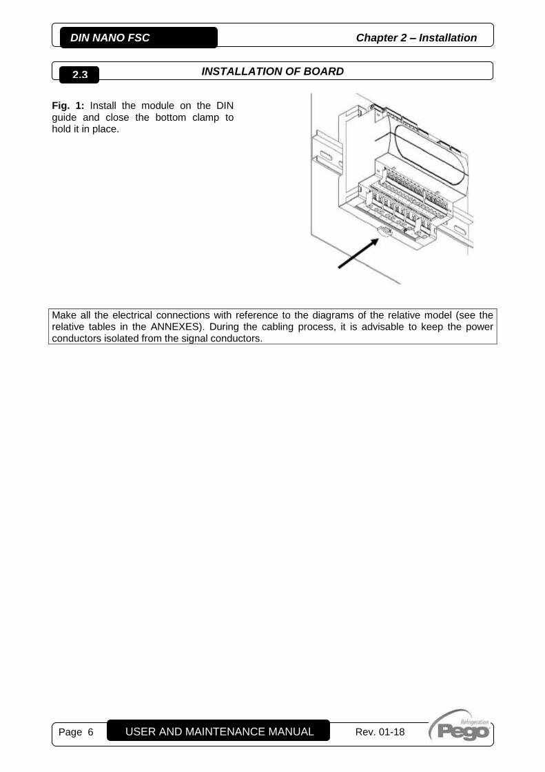
Fig. 1: Install the module on the DIN guide and close the bottom clamp to hold it in place.
Make all the electrical connections with reference to the diagrams of the relative model (see the relative tables in the ANNEXES). During the cabling process, it is advisable to keep the power conductors isolated from the signal conductors.
2.3
Chapter 3 – Technical features DIN NANO FSC
USER AND MAINTENANCE MANUAL
Rev. 01-18 Page 7
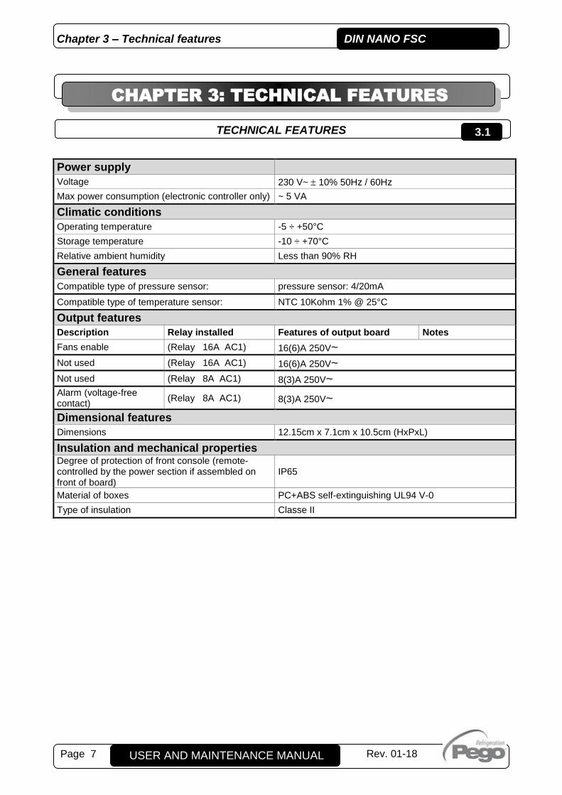
TECHNICAL FEATURES
Power supply
Voltage 230 V~ 10% 50Hz / 60Hz
Max power consumption (electronic controller only) ~ 5 VA
Climatic conditions
Operating temperature -5 ÷ +50°C
Storage temperature -10 ÷ +70°C
Relative ambient humidity Less than 90% RH
General features
Compatible type of pressure sensor: pressure sensor: 4/20mA
Compatible type of temperature sensor: NTC 10Kohm 1% @ 25°C
Output features
Description Relay installed Features of output board Notes
Fans enable (Relay 16A AC1) 16(6)A 250V~
Not used (Relay 16A AC1) 16(6)A 250V~
Not used (Relay 8A AC1) 8(3)A 250V~
Alarm (voltage-free contact)
(Relay 8A AC1) 8(3)A 250V~
Dimensional features
Dimensions 12.15cm x 7.1cm x 10.5cm (HxPxL)
Insulation and mechanical properties Degree of protection of front console (remote-controlled by the power section if assembled on front of board)
IP65
Material of boxes PC+ABS self-extinguishing UL94 V-0
Type of insulation Classe II
CHAPTER 3: TECHNICAL FEATURES
3.1

DIN NANO FSC Chapter 4 – Terms of guarantee
USER AND MAINTENANCE MANUAL
Rev. 01-18 Page 8
TERMS OF THE GUARANTEE The NANO DIN electronic controls are guaranteed against all manufacturing defects for 24 months from the date in the production identification code. In the event of defects, the device must be returned properly packaged to our Site or authorized assistance center after requesting and receiving the authorization number for returning the product. The Customer has the right to repair the defective device inclusive of manual labor and spare parts. The Customer assumes sole responsibility for the expenses and the risks associated with transport. All work carried out under the terms of the guarantee does not renew or extend the duration of the guarantee. The guarantee does not cover:
Damage attributable to tampering, negligence, carelessness or inadequate installation of the device.
Installation, use or maintenance not in compliance with the rules and instructions provided with the device.
Repairs carried out by unauthorised personnel.
Damage attributable to natural causes like lightning, natural disasters, etc. In all the above cases, the customer pays for the cost of repair.
Request for repairs under the terms of the guarantee may be refused if the device has been modified or converted. PEGO S.r.l. cannot assume responsibility for any loss of data or information, the cost of replacement goods or services, injury to people or animals, loss of sales or earnings, downtime, and any direct, indirect, accidental, pecuniary, collateral, punitive, special or consequential damage or loss caused in any way, within or outside the scope of the contract or due to negligence or other responsibilities associated with use or installation of the product. The guarantee is terminated automatically in the event of poor operation attributable to tampering, collisions and inadequate installation. It is obligatory to observe all the rules in this manual and the operating conditions of the device. PEGO S.r.l. cannot assume any responsibility for inaccuracies in this manual attributable to printing or transcription errors. PEGO S.r.l. reserves the right to make changes to its products that it considers necessary or useful without affecting their essential characteristics. Each new release of the manuals for PEGO's products replaces all previous releases. Unless specified otherwise, the guarantee is governed by the rules in force and, in particular, article 1512 of the Italian Civil Code. All disputes are settled at the Court of Rovigo.
4.1
CHAPTER 4: TERMS OF THE GUARANTEE

Chapter 5 – Data programming DIN NANO FSC
Page 9 USER AND MAINTENANCE MANUAL
Rev. 01-18
CONTROL PANEL
FRONT KEYPAD
(1)
UP KEY Increases value / Scrolls up through parameters Acquires an alarm.
(2)
DOWN KEY Decreases value / Scrolls down through parameters.
(3)
STAND-BY If pressed for more than 1 sec., the Stand-by state will alternate with the normal operating status, and vice versa. In the stand-by state, the system stops and the display will change the writing OFF with the current view. If pressed, it switches the display view from °C to Bar and vice versa.
(4)
SET Shows the set point Enables configuration of the set point when pressed together with the Down or UP key.
CHAPTER 5: DATA PROGRAMMING
5.1
5.2
(1)
(2)
(3)
(4) (5)
(6) (7) (10) (14) (8) (11)
(9) (12) (13)

DIN NANO FSC Chapter 5 – Data programming
USER AND MAINTENANCE MANUAL
Rev. 01-18 Page 10
DISPLAY LED
(5)
Shows the values / parameters
(6)
"OUTPUT NO.1” ICON
ON=analogue output between 0.1 and 3.3V.
(7) "OUTPUT NO.2" ICON
ON=analogue output between 3.4 and 6.6V.
(8) "OUTPUT NO.3" ICON
ON = analogue output > 6.6V.
(9)
"PRG" ICON
Flashing LED = Programming (or SET POINT change)
(10)
---
(11) "CONDENSER FAN CONTROL" ICON
LED ON = Condenser Fan Control ENABLED
(12) "UNIT OF MEASURE IN DEGREES CELSIUS" ICON
LED ON = Unit of measure in degrees Celsius of the viewed value.
(13)
"UNIT OF MEASUREMENT IN BAR" ICON
LED ON = Unit of measure in Bar of the viewed value.
(14)
ALARM IN PROGRESS ICON
LED OFF = No alarm triggered LED ON = Alarm triggered and then cancelled Blinking LED = Alarm in progress
5.3

Chapter 5 – Data programming DIN NANO FSC
Page 11 USER AND MAINTENANCE MANUAL
Rev. 01-18
COMBINATION OF KEYS
+
LEVEL 1 PROGRAMMING Pressing both keys together for more than 3 seconds enables access to the Level 1 programming menu.
EXIT PROGRAMMING Pressing both keys together for more than 3 seconds in any programming menu exits the menu concerned.
+ + LEVEL 2 PROGRAMMING Pressing all keys together for more than 3 seconds enables access to the Level 2 programming menu. To exit the menu, press the up and down arrow keys together.
+ LEVEL 3 PROGRAMMING Pressing both keys together for more than 3 seconds enables access to the Level 3 programming menu. To exit the menu, press the up and down arrow keys together.
pressed
+
SWITCHING FROM Bar to °C WHILE VIEWING THE VALUE OF THE FOLLOWING VARIABLES IN Bar, if Pt=0.
The variables involved with this kind of view are: SET POINT, r0, LSE, HSE, A1, A2, iOv, nSC.
When displaying the value contained in one of the variables listed above, pressing the stand-by key switches the view from Bar to °C according to the table of the gas type selected until the keys are released.
5.4

DIN NANO FSC Chapter 5 – Data programming
USER AND MAINTENANCE MANUAL
Rev. 01-18 Page 12
VIEWING AND CONFIGURATION OF SET POINT The SETPOINT is set in Bar if the adjustment is made by a pressure sensor (if Pt = 0). In the case in which
the adjustment is made by means of temperature sensor (NTC) SETPOINT is expressed in ° C (if Pt = 1).
The procedure for changing the SET is the following:
1. Press the SET key to view the current Bar/°C SET POINT value.
2. Pressing and holding the SET key and pressing one of the keys () or () alters the value of the Bar/°C
SETPOINT.
Release the SET key to return to the value of the adjustment sensor. Any changes made are saved
automatically.
While viewing the SET POINT value in Bar (then with Pt=0 and SET button pressed), if you press the
standby key at the same time, you will view the value changed to °C depending on the type of Gas set.
While viewing the value in °C, it will not be possible to change the set through the arrows.
LEVEL 1 PROGRAMMING (User level)
To access Level 1 programming, press and hold the UP key () and DOWN key () for over 3 seconds.
When the first programming variable appears:
1. Select the variable you want to change with the key () or with the key (). After selecting the required
variable, it is possible to:
2. View its configuration by pressing the SET key.
3. Edit configuration by pressing and holding the SET key and pressing either the () or () key.
4. After setting the configuration values, press and hold both the () key and the () key for a few seconds
until the cell temperature value appears and exit the menu. The system closes the menu when the keypad is
not used for over 30 seconds.
5. Any changes made to the variables are saved automatically when the system closes the configuration
menu.
LIST OF LEVEL 1 VARIABLES (User Level)
LABEL MEANING VALUES DEFAULT default
Pt
r0 SET differential
Value always greater than (iOv) value
with Pt=0 (regulation with pressure
probe)
0,6 5,0 Bar
(with Pt=0)
2,0 Bar
* with Pt=1 or (Pt=0 and mOd=1)
(regulation with temperature probe)
1,0 50,0 °C
with Pt=1 or (Pt=0 and mOd=1)
15,0 °C
t1 The minimum time that must elapse between two successive insertions of the fans. (SECONDS)
0 500 step 2 sec
10
t2 The minimum time that must elapse between one shutdown and the next insertion of the fans. (SECONDS)
0 500 step 2 sec
0
Fty Type of refrigerant GAS in use.
The setting of this parameter is essential for correct operation.
0 = R404 1 = R134 2 = R22 3 = R407A 4 = R407F 5 = R410A 6 = R507
10 = R32 11 = R448A 12 = R452A 13 = R600 14 = R600A 15 = R1270 16 = R1234ze
0
5.6
5.7
5.5

Chapter 5 – Data programming DIN NANO FSC
Page 13 USER AND MAINTENANCE MANUAL
Rev. 01-18
7=R744(CO2) 8 = R449A 9 = R290
17 = R23 18 =R717(NH3)
UM
View unit of measurement
If Pt = 0 it is possible to choose the unit of measurement. if Pt = 1 the control temperature is always displayed in ° C.
0 = bar 1 = °C
0
AO1 Display of the 0-10V analogue output for condenser fans
0,0 – 10,0V read-only
tA Display ambient temperature (if mOd = 1 or 2)
-45.0 – 99.0 °C if mOd=1 or 2
read-only
ALL View of the last alarm triggered Alarm code read-only
A1
Minimum pressure/temperature alarm
The absolute pressure/temperature referring to the regulation probe below which, once the Ald delay time is activated, the LOW pressure alarm is triggered showing EL alternating with the
pressure/temperature on the display and the flashing of the alarm icon. When the alarm turns off, the "alarm presence" icon will remain lit to indicate which operation has occurred until the UP button is pressed
with Pt=0
-0,6 ÷ (A2-0,2) Bar step 0,2 Bar
-0,6 Bar
* with Pt=1 or
(Pt=0 and mOd=1)
-45,0 ÷ (A2-0,2) °C step 0,2 °C
-45,0 °C
A2
Maximum pressure/temperature alarm
The absolute pressure/temperature referring to the regulation probe above which, once the Ald delay time is activated, the HIGH pressure/temperature alarm is triggered showing EH alternating
with the pressure on the display and the flashing of the alarm icon. When the alarm turns off, the "alarm presence" icon will remain lit to indicate which operation has occurred until the UP button is pressed
with Pt=0
(A1+0,2) ÷ +30,0 Bar step 0,2 Bar
+30,0 Bar
* with Pt=1 or
(Pt=0 and mOd=1)
(A1+0,2) ÷ +99,0 °C step 0,2 °C
99,0 °C
tdS Day start time 00,0 ÷ 23,5 6,0
tdE Day end time 00,0 ÷ 23,5 22,0
DIN NANO FSC Chapter 5 – Data programming
USER AND MAINTENANCE MANUAL
Rev. 01-18 Page 14
LEVEL 2 PROGRAMMING (Installer level) To access Level 2 programming, press and hold the UP key (), DOWN key () and STAND-BY key for
over 3 seconds.
When the first programming variable appears:
1. Select the variable you want to change with the key () or with the key (). After selecting the required
variable, it is possible to:
2. View its configuration by pressing the SET key.
3. Edit configuration by pressing and holding the SET key and pressing either the () or () key.
4. After setting the configuration values, press and hold both the () key and the () key for a few seconds
until the cell temperature value appears and exit the menu.
5. Any changes made to the variables are saved automatically when the system closes the configuration
menu.
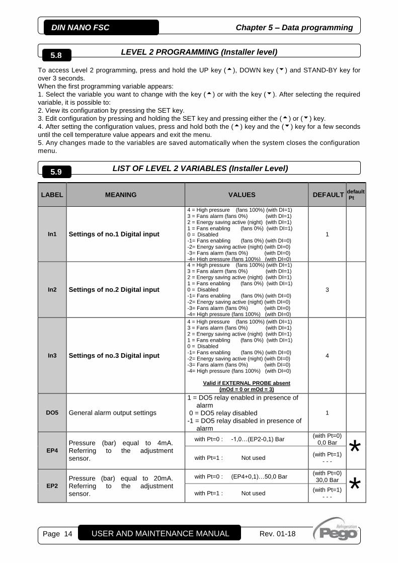
LIST OF LEVEL 2 VARIABLES (Installer Level)
LABEL MEANING VALUES DEFAULT default Pt
In1 Settings of no.1 Digital input
4 = High pressure (fans 100%) (with DI=1) 3 = Fans alarm (fans 0%) (with DI=1) 2 = Energy saving active (night) (with DI=1) 1 = Fans enabling (fans 0%) (with DI=1) 0 = Disabled -1= Fans enabling (fans 0%) (with DI=0) -2= Energy saving active (night) (with DI=0) -3= Fans alarm (fans 0%) (with DI=0) -4= High pressure (fans 100%) (with DI=0)
1
In2 Settings of no.2 Digital input
4 = High pressure (fans 100%) (with DI=1) 3 = Fans alarm (fans 0%) (with DI=1) 2 = Energy saving active (night) (with DI=1) 1 = Fans enabling (fans 0%) (with DI=1) 0 = Disabled -1= Fans enabling (fans 0%) (with DI=0) -2= Energy saving active (night) (with DI=0) -3= Fans alarm (fans 0%) (with DI=0) -4= High pressure (fans 100%) (with DI=0)
3
In3 Settings of no.3 Digital input
4 = High pressure (fans 100%) (with DI=1) 3 = Fans alarm (fans 0%) (with DI=1) 2 = Energy saving active (night) (with DI=1) 1 = Fans enabling (fans 0%) (with DI=1) 0 = Disabled -1= Fans enabling (fans 0%) (with DI=0) -2= Energy saving active (night) (with DI=0) -3= Fans alarm (fans 0%) (with DI=0) -4= High pressure (fans 100%) (with DI=0)
Valid if EXTERNAL PROBE absent (mOd = 0 or mOd = 3)
4
DO5 General alarm output settings
1 = DO5 relay enabled in presence of alarm
0 = DO5 relay disabled -1 = DO5 relay disabled in presence of
alarm
1
EP4
Pressure (bar) equal to 4mA. Referring to the adjustment sensor.
with Pt=0 : -1,0…(EP2-0,1) Bar (with Pt=0)
0,0 Bar
* with Pt=1 : Not used (with Pt=1)
- - -
EP2
Pressure (bar) equal to 20mA. Referring to the adjustment sensor.
with Pt=0 : (EP4+0,1)…50,0 Bar (with Pt=0) 30,0 Bar
* with Pt=1 : Not used (with Pt=1)
- - -
5.8
5.9

Chapter 5 – Data programming DIN NANO FSC
Page 15 USER AND MAINTENANCE MANUAL
Rev. 01-18
iOv
Offset Inverter fans Value always less than the (r0) value
0,5 … 2,5 bar if Pt=0 always < r0
0,5 Bar
* 0,9 … 10,0 °C if Pt=1 or (Pt=0 and mOd=1) always < r0
0,9 °C
iLv Inverter fans: minimum 0-10V output value setting
0,0 … 10,0 V 3,0 V
iHv
Inverter fans: maximum 0-10V output value setting
0,0 … 10,0 V 10,0 V
bOv
Boost fans: Time for which the 0-10V output of the fans is pushed to 100%. This is used to win the breakaway at their start. (SECONDS)
0 240 sec 2 sec LSE
Minimum value that can be attributed to set point
with Pt=0 0…(HSE-0,2) Bar, step 0,2 Bar
(with Pt=0) 10,0 Bar * with Pt=1 or (Pt=0 and mOd=1)
-45,0…(HSE-0,2) °C, step 0,2 °C (with Pt=1) -45,0 °C
HSE Maximum value that can be attributed to set point
with Pt=0 (LSE+0,2)…30,0 Bar, step 0,2 Bar
(with Pt=0) 25,0 Bar *
with Pt=1 or (Pt=0 and mOd=1) (LSE+0,2)…99,0 °C, step 0,2 °C
(with Pt=1) 99,0 °C
Ald
Minimum or maximum pressure/temperature alarm signalling and display delay time.
0…240 min 120 min CL1 Adjustment sensor calibration -10,0…+10,0 Bar or °C 0,0
CL2 Ambient sensor calibration -10,0…+10,0 °C 0,0 °C
tAM Minimum ambient temperature -45,0 … 99,0 °C 0,0 °C
dAt Differential ambient temperature 1,0 … 99,0 °C 50,0 °C
iMv
If mOd = 2: Maximum value that can take the minimum voltage 0-10 V in the case of ambient temperature compensation If mOd=3: 0-10V output fixed value
iLv … iHv 5,0 V
dnE
Night mode enable (energy saving) At night operation decimal point flashes. (dnE forced to 0 if mOd=1)
0 = disabled 1 = enabled
0
DIN NANO FSC Chapter 5 – Data programming
USER AND MAINTENANCE MANUAL
Rev. 01-18 Page 16
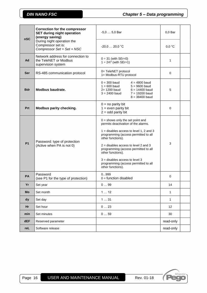
nSC
Correction for the compressor SET during night operation (energy saving) During night operation the Compressor set is: Compressor Set = Set + NSC
-5,0 … 5,0 Bar 0,0 Bar -20,0 … 20,0 °C 0,0 °C
Ad
Network address for connection to the TeleNET or Modbus supervision system
0 ÷ 31 (with SEr=0) 1 ÷ 247 (with SEr=1)
1 Ser RS-485 communication protocol
0= TeleNET protocol 1= Modbus-RTU protocol
0
Bdr Modbus baudrate.
0 = 300 baud 1 = 600 baud 2= 1200 baud 3 = 2400 baud
4 = 4800 baud 5 = 9600 baud 6 = 14400 baud 7 = 19200 baud 8 = 38400 baud
5 Prt Modbus parity checking.
0 = no parity bit 1 = even parity bit 2 = odd parity bit
0
P1 Password: type of protection (Active when PA is not 0)
0 = shows only the set point and permits deactivation of the alarms. 1 = disables access to level 1, 2 and 3 programming (access permitted to all other functions). 2 = disables access to level 2 and 3 programming (access permitted to all other functions). 3 = disables access to level 3 programming (access permitted to all other functions).
3
PA Password (see P1 for the type of protection)
0...999
0 = function disabled 0
Yr Set year 0 … 99 14
Mo Set month 1 … 12 1
dy Set day 1 … 31 1
Hr Set hour 0 … 23 12
min Set minutes 0 … 59 30
dEF Reserved parameter read-only
reL Software release read-only

Chapter 5 – Data programming DIN NANO FSC
Page 17 USER AND MAINTENANCE MANUAL
Rev. 01-18
LEVEL 3 PROGRAMMING (Installer level) To access Level 3 programming, press and hold the UP key () and STAND-BY key for over 3 seconds.
When the first programming variable appears:
1. Select the variable you want to change with the key () or with the key (). After selecting the required
variable, it is possible to:
2. View its configuration by pressing the SET key.
3. Edit configuration by pressing and holding the SET key and pressing either the () or () key.
4. After setting the configuration values, press and hold both the () key and the () key for a few seconds
until the cell temperature value appears and exit the menu.
5. Any changes made to the variables are saved automatically when the system closes the configuration
menu.
LIST OF LEVEL 3 VARIABLES (Installer Level)
LABEL MEANING VALUES DEFAULT default
Pt
Pt
Adjustment probe type:
PLEASE NOTE: the Pt Exchange involves loading default
settings dedicated on the variables marked with an asterisk in the "default Pt" column. Modify the internal jumpers as described in
section “A.2 Connection diagram”, consistent with the type of probe
connected
0 = Pressure. The control probe is a 4-20 mA pressure sensor connected to terminals 23-24 (see connection diagram) 1 = Temperature. The control probe is a NTC 10K temperature sensor connected to terminals 23-24 (see connection diagram)
0
mOd
Operating mode If mOd = 1 or mOd = 2 you need to connect an external temperature sensor (term. 21-22)
0 = normal mode 1 = energy saving 2 = low noise 3 = Fixed speed (0-
10V output equal to iMv)
0
SP1 Speed of reaction to changes of regulating probe (terminals 23-24)
0 = fast 1 = normal 2 = slow 3 = very slow
1
SP2 Speed of reaction to changes of External ambient probe (terminals 21-22)
0 = fast 1 = normal 2 = slow 3 = very slow
1
5.10
5.11

DIN NANO FSC Chapter 5 – Data programming
USER AND MAINTENANCE MANUAL
Rev. 01-18 Page 18
OPERATING MODE
The condenser fans are controlled via a 0-10V analogue output and sideband-type adjustment. The LED icon (11) turns on to identify the fan condenser control. The regulation probe (terminal 23 /24) can be of two types:
- Flow pressure probe 4-20mA (parameter Pt = 0) - Condensing temperature probe NTC 10KΩ (parameter Pt = 1)
The setting of parameter Pt according to the type of probe connected must be combined with the correct setting of the jumpers on the NDINFSC board (see connection diagram). Changing the Pt involves loading the relevant default parameters on the variables marked with an asterisk in the “default Pt” column and changing the unit of measure of some parameters (Bar if the probe connected is a pressure probe, °C if the probe connected is a temperature probe). There are various fan control modes available.
CONTROL IN THE EVENT OF ALARMS
With the presence of ‘fans alarm’, the analog output is immediately brought to 0V and then open the digital
output 1 (inverter off). In addition, the display shows alarm (Ev).
NORMAL MODE (mOd = 0)
The adjustment follows the operation of graph no.1 with the increase of the output pressure/condensing
temperature and the decrease of graph no.2. For simplicity, we define the value of the probe pressure /
temperature as adjustment probe. Adjustment probe value INCREASE (Graph n.1): The analogue output of the adjuster will be 0V for output pressure probe less or equal to point (B) representing the "SET point + iOv offset" value.
If the adjustment probe value is higher than
point (B), you will have the analogue output
at (iHv) for the maximum BOv time. BOv is
the Fans Boost times for which the adjuster
output is increased by 100% in order to help
the start-up of the fans.
Between points (B) and (C), the analogue
output will have a value proportional to the
value of the adjustment probe starting from
the minimum value of the parameter (iLv) up
to the maximum value of the parameter (iHv).
With adjustment probe value equal or higher
than point (C), you will have a (iHv) analogue
output.
Digital output no.1 represents "the condenser
fans inverter activation" and is ON for
adjustment probe value higher than or equal
to the set point and OFF for lower values.
5.13
Graph. n.1
5.13.1
Chapter 5 – Data programming DIN NANO FSC
Page 19 USER AND MAINTENANCE MANUAL
Rev. 01-18
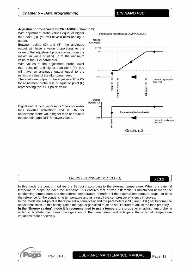
Adjustment probe value DECREASING (Graph n.2):
With adjustment probe values equal or higher
than point (D), you will have a (iHv) analogue
output.
Between points (D) and (E), the analogue
output will have a value proportional to the
value of the adjustment probe starting from the
maximum value of (iHv) up to the minimum
value of the (iLv) parameter.
With values of the adjustment probe lower
than point (E) and higher than point (F), you
will have an analogue output equal to the
minimum value of the (iLv) parameter.
The analogue output of the adjuster will be 0V
for adjustment probe less or equal to point (F)
representing the "SET point" value.
Digital output no.1 represents "the condenser
fans inverter activation" and is ON for
adjustment probe value higher than or equal to
the set point and OFF for lower values.
ENERGY SAVING MODE (mOd = 1)
In this mode the control modifies the Set-point according to the external temperature. When the external temperature drops, so does the set-point. This ensures that a fixed differential is maintained between the condensing temperature and the external temperature, therefore if the external temperature drops, so does the reference for the condensing temperature and as a result the compressor efficiency improves. In this mode the set-point is therefore set automatically and the parameters (LSE) and (HSE) set become the adjustment limits. In this configuration the type of gas used must be set, in order to adjust the fans properly. In the “Energy saving” mode it is recommended to use a temperature probe as an adjustment probe, in order to facilitate the correct configuration of the parameters and anticipate the external temperature variations more effectively.
Graph. n.2
5.13.2

DIN NANO FSC Chapter 5 – Data programming
USER AND MAINTENANCE MANUAL
Rev. 01-18 Page 20
LOW NOISE MODE (mOd = 2)
By connecting a room temperature probe it is possible to anticipate and counteract the effects of the variation of the external climatic conditions on the setting (system pressure / condensing temperature). This function can be particularly useful because, if configured appropriately, it can reduce the speed of the condenser fans (and therefore their noise and their consumption) if the external temperature drops, such as at night or during the winter season. Operation The minimum speed of the fans increases as the external temperature by combining a variation of the external temperature equal to dAt with a variation of the minimum control voltage equal to (iMV - iLV). To take advantage of the external temperature compensation it is therefore advisable to set the parameter (tAm) at the minimum external temperature estimated throughout the course of the year and the parameter (dAt) at the maximum temperature excursion. The compensation algorithm varies the fan speed so that the temperature (tAm) is associated with the minimum speed iLv, while the temperature (tAm + dAt) is associated with the maximum speed iMv. The minimum fan speed at a certain external temperature is calculated as:
𝑉𝑚𝑖𝑛 = (𝑡𝑒𝑥𝑡 − 𝑡𝐴𝑀
𝑑𝐴𝑡) (𝑖𝑀𝑣 − 𝑖𝐿𝑣) + 𝑖𝐿𝑣
5.13.3
tA (External ambient temperature)
time
T (°C)
dAt
HSE
LSE
Setpoint of condensing

Chapter 5 – Data programming DIN NANO FSC
Page 21 USER AND MAINTENANCE MANUAL
Rev. 01-18
As you can see in Chart 3, the variation of the output follows the same trend shown in the previous sections (for simplicity's sake, the fan initial start-up BOv boost is not shown in the chart): however, it is possible to see that varying the minimum fan speed actually changes the entire operating curve, according to the external temperature.
FIXED SPEED MODE (mOd = 3) In this mode, the 0-10 V fan control output takes on a fixed value, equal to parameter iMv. The enabling analogue output and digital output are active only if the NDINFSC controller is enabled. When the enabling is received, the fans go to full speed (iHv) for a BOv time period (fan boost), then the fans go to the value set in iMv. In this mode the alarms EH, EL, E0 and E1 are disabled, and it is not necessary to connect the temperature or pressure probes to the analogue inputs.
Graph. n.3
5.13.4

DIN NANO FSC Chapter 5 – Data programming
USER AND MAINTENANCE MANUAL
Rev. 01-18 Page 22
The day/night mode is activated by setting parameter dnE = 1. During the night the pressure Set-point is therefore modified as: Set-point (night) = Set-point (day) + nSC Night operation may be activated:
- from the digital input, setting (In1)=±1, (In2)=±1 or (In3)=±1); - via the internal clock, when the current time is greater than (tdE) and less than (tdS).
If a digital input is configured as a day/night input, the internal clock is ignored.
PASSWORD FUNCTION The password function is enabled by setting a value other than 0 in the PA parameter. See parameter P1 for the various levels of protection. Protection is enabled automatically when the keypad is not used for 30 seconds. The digits 000 appear on the display. Use the up/down arrow keys to edit the number and press the SET key to confirm. The 000 password window disappears if the keypad is not used for 30 seconds. If you forget the password, use the universal number 100.
NIGHT / DAY FUNCTION 5.14
5.15

Chapter 6 - Options DIN NANO FSC
USER AND MAINTENANCE MANUAL
Rev. 01-18 Page 23
TELENET MONITORING/SUPERVISION SYSTEM In order to connect the board to the TeleNET network, follow the diagram below. Configure the instrument with reference to the TeleNET manual. IMPORTANT: During configuration of the “Module”, select "TWMT instrument " or "TWMP instrument ". In detail:
- Ad address: shows regulation temperature probe value (TWMT) / regulation pressure probe value (TWMP) / converted regulation temperature probe value (TWMT)
- Ad + 1 address: shows external ambient temperature probe value (TWMT)
CONFIGURATION OF NETWORK WITH MODBUS-RTU PROTOCOL Connect the board to a RS485 network with Modbus-RTU protocol with reference to the diagram below. Refer to the MODBUS-RTU_DIN_NANO_FSC manual (available on our website) for the specifications of the MODBUS-RTU communication protocol.
CHAPTER 6: OPTIONS
6.1
6.2

DIN NANO FSC Chapter 7 - Diagnostics
USER AND MAINTENANCE MANUAL
Rev. 01-18 Page 24
DIAGNOSTICS The controller DIN NANO FSC, in the case of any anomalies, will warn the operator through alarm codes shown on the display. The code of the last alarm triggered will be stored and can be displayed as only-read within the first level ALL variable. The view of this variable at the first commissioning (with empty memory) will display - - -. One of the following messages appears on the screen when an alarm condition occurs:
CODE POSSIBLE CAUSE / DESCRITPION ACTION TO BE TAKEN RESET
E0
Operation anomalies of the adjustment probe (terminals 23-24) (The outputs are all disabled apart from the alarm outputs) Disabled if mOd = 3
Check the probe status. automatic
E1
Operation anomalies of the External ambient NTC probe (terminals 21-22) (The regulation goes on but turns off the outdoor temperature compensation) Disabled if mOd = 3
Check the probe status. automatic
E3
EEPROM ALARM An error was found in the EEPROM memory. (The outputs are all disabled apart from the alarm outputs)
Switch the appliance off and back on
If the problem persists, replace the Control Circuit Board
manual
Requires shut-down
Ev
Condenser fans protection (i.e. thermal protection) It is activated if there is an alarm input fans. The 0-10V output is set to 0V.
Check the status of the fans
Check the absorption of the fans
Check the status of the digital input
automatic
EHI
High pressure alarm (DI) High pressure alarm from digital input. The fans are forced to 100% (iHv) in order to reduce the circuit pressure.
Check the refrigerant circuit
If the problem persists contact the technical assistance service
automatic
EH High pressure/temperature alarm (fans 100% of iHv) Disabled if mOd = 3
Check the refrigerant circuit
If the problem persists contact the technical assistance service
automatic
EL Low pressure/temperature alarm (fans 0% of iHv) Disabled if mOd = 3
Check the refrigerant circuit
If the problem persists contact the technical assistance service
automatic
iEn No enabling consent Check enabling consent automatic
CHAPTER 7: DIAGNOSTICS
7.1

Annexes DIN NANO FSC
Page 25 USER AND MAINTENANCE MANUAL
Rev. 01-18
EC DECLARATION OF CONFORMITY LA PRESENTE DICHIARAZIONE DI CONFORMITA’ E’ RILASCIATA SOTTO LA RESPONSABILITA’ ESCLUSIVA DEL FABBRICANTE:
THIS DECLARATION OF CONFORMITY IS ISSUED UNDER THE EXCLUSIVE RESPONSIBILITY OF THE MANUFACTURER:
PEGO S.r.l. Via Piacentina 6/b, 45030 Occhiobello (RO) – Italy –
DENOMINAZIONE DEL PRODOTTO IN OGGETTO / DENOMINATION OF THE PRODUCT IN OBJECT
MOD.: 200NDINFSC01
IL PRODOTTO DI CUI SOPRA E’ CONFORME ALLA PERTINENTE NORMATIVA DI ARMONIZZAZIONE DELL’UNIONE EUROPEA: THE PRODUCT IS IN CONFORMITY WITH THE RELEVANT EUROPEAN HARMONIZATION LEGISLATION:
Direttiva Bassa Tensione (LVD): 2014/35/UE Low voltage directive (LVD): 2014/35/EU Direttiva EMC: 2014/30/CE Electromagnetic compatibility (EMC): 2014/30/EU
LA CONFORMITA’ PRESCRITTA DALLA DIRETTIVA E’ GARANTITA DALL’ADEMPIMENTO A TUTTI GLI EFFETTI DELLE SEGUENTI NORME:
THE CONFORMITY REQUIRED BY THE DIRECTIVE IS GUARANTEED BY THE FULFILLMENT TO THE FOLLOWING STANDARDS:
Norme armonizzate: EN 60730-1:2011, EN 60730-2-9:2010, EN 61000-6–1:2007, EN 61000-6–3:2007 European standards: EN 60730-1:2011, EN 60730-2-9:2010, EN 61000-6–1:2007, EN 61000-6–3:2007
IL PRODOTTO E’ COSTITUITO PER ESSERE INCORPORATO IN UNA MACCHINA O PER ESSERE ASSEMBLATO CON ALTRI MACCHINARI PER COSTITUIRE UNA MACCHINA CONSIDERATE DALLA DIRETTIVA: 2006/42/CE “Direttiva Macchine”. THE PRODUCT HAS BEEN MANUFACTURED TO BE INCLUDED IN A MACHINE OR TO BE ASSEMBLED TOGHETER WITH OTHER MACHINERY TO COMPLETE A MACHINE ACCORDING TO DIRECTIVE: EC/2006/42 “Machinery Directive”. Firmato per nome e per conto di: Signed for and on behalf of:
ANNEXES
A.1
Luogo e Data del rilascio: Place and Date of Release:
Occhiobello (RO), 08/01/2018
DIN NANO FSC Annexes
USER AND MAINTENANCE MANUAL
Rev. 01-18 Page 26
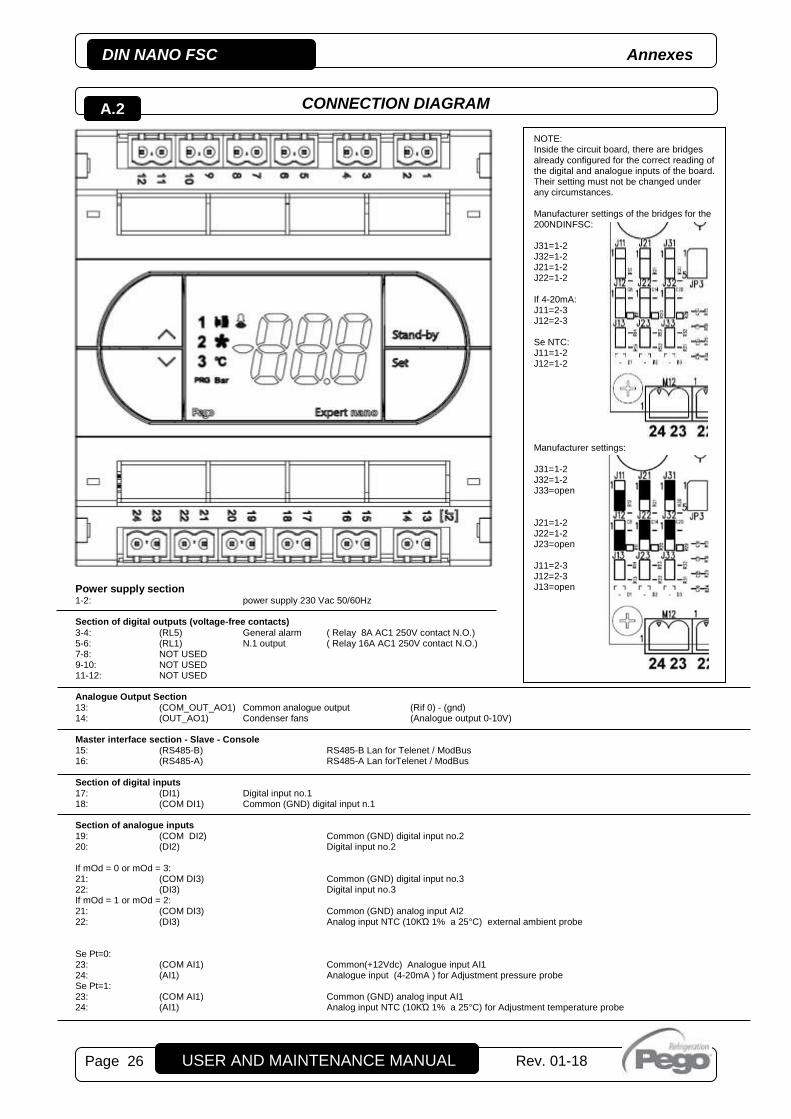
CONNECTION DIAGRAM
Power supply section 1-2: power supply 230 Vac 50/60Hz Section of digital outputs (voltage-free contacts)
3-4: (RL5) General alarm ( Relay 8A AC1 250V contact N.O.) 5-6: (RL1) N.1 output ( Relay 16A AC1 250V contact N.O.) 7-8: NOT USED 9-10: NOT USED 11-12: NOT USED Analogue Output Section 13: (COM_OUT_AO1) Common analogue output (Rif 0) - (gnd) 14: (OUT_AO1) Condenser fans (Analogue output 0-10V) Master interface section - Slave - Console 15: (RS485-B) RS485-B Lan for Telenet / ModBus 16: (RS485-A) RS485-A Lan forTelenet / ModBus Section of digital inputs 17: (DI1) Digital input no.1 18: (COM DI1) Common (GND) digital input n.1 Section of analogue inputs 19: (COM DI2) Common (GND) digital input no.2 20: (DI2) Digital input no.2 If mOd = 0 or mOd = 3: 21: (COM DI3) Common (GND) digital input no.3 22: (DI3) Digital input no.3 If mOd = 1 or mOd = 2: 21: (COM DI3) Common (GND) analog input AI2 22: (DI3) Analog input NTC (10KΏ 1% a 25°C) external ambient probe Se Pt=0: 23: (COM AI1) Common(+12Vdc) Analogue input AI1 24: (AI1) Analogue input (4-20mA ) for Adjustment pressure probe Se Pt=1: 23: (COM AI1) Common (GND) analog input AI1 24: (AI1) Analog input NTC (10KΏ 1% a 25°C) for Adjustment temperature probe
NOTE: Inside the circuit board, there are bridges already configured for the correct reading of the digital and analogue inputs of the board. Their setting must not be changed under any circumstances. Manufacturer settings of the bridges for the 200NDINFSC: J31=1-2 J32=1-2 J21=1-2 J22=1-2 If 4-20mA: J11=2-3 J12=2-3 Se NTC: J11=1-2 J12=1-2
Manufacturer settings: J31=1-2 J32=1-2 J33=open J21=1-2 J22=1-2 J23=open J11=2-3 J12=2-3 J13=open
A.2
Annexes DIN NANO FSC
Page 27 USER AND MAINTENANCE MANUAL
Rev. 01-18
REMARKS

DIN NANO FSC Annexes
USER AND MAINTENANCE MANUAL
Rev. 01-18 Page 28
PEGO s.r.l.
Via Piacentina, 6/b 45030 Occhiobello ROVIGO - ITALY
Tel. +39 0425 762906 Fax +39 0425 762905
e.mail: [email protected] – www.pego.it
AFTER-SALES ASSISTANCE CENTRE
Tel. +39 0425 762906 e.mail: [email protected]
Distributor:
PEGO s.r.l. reserves the right to make amendments to this user manual at any moment.