Embed Size (px)
Citation preview
1
CHAPTER 1
INTRODUCTION
1.1 NEEDS FOR MICROMACHINING
There is a growing demand for industrial products with increased
number of functions and of reduced dimensions. Micro-machining is the most
basic technology for the production of such miniature parts and components.
Micro machining is defined as the ability to produce features with the dimensions
from 1 m to 999 m or when the volume of the material removed is at the micro
level. Lithography based micro-machining technology uses silicon as material to
produce integrated circuitry components and microstructures. However, these
methods, in general, lack the ability of machining three-dimensional shapes
because of poor machining control in the Z axis. Fabrication using hard and
difficult-to-machine materials such as tool steels, composites, super alloys,
ceramics, carbides, heat resistant steels and complex geometries for demanding
aerospace, mechanical or biomedical applications requires alternative novel
methods.
1.2 APPLICATIONS OF MICROMACHINING
In recent years, manufacturing industry has witnessed a rapid increase
in demand for micro-products and micro-components in many industrial sectors
including the electronics, optics, medical, biotechnology and automotive sectors.
Examples of applications include medical implants, drug delivery systems,
2
diagnostic devices, connectors, switches, micro-reactors, micro-engines, micro-
pumps and printing heads. These micro-system-based products represent key
value-adding elements for many companies and, thus, an important contributor to
a sustainable economy (Brousseau et al. 2010). As a result of the current trend
towards product miniaturization, there is a demand for advances in micro- and
nano- manufacturing technologies and their integration in new manufacturing
platforms. These platforms must enable both function integration (i.e.
combination of different functions) and length-scale integration (i.e. mixing of
the macro-, micro- and nano-dimensions) in existing and new products and, at the
same time, their cost effective manufacture in a wide range of materials.
1.2.1 Production of Micro-Compressor
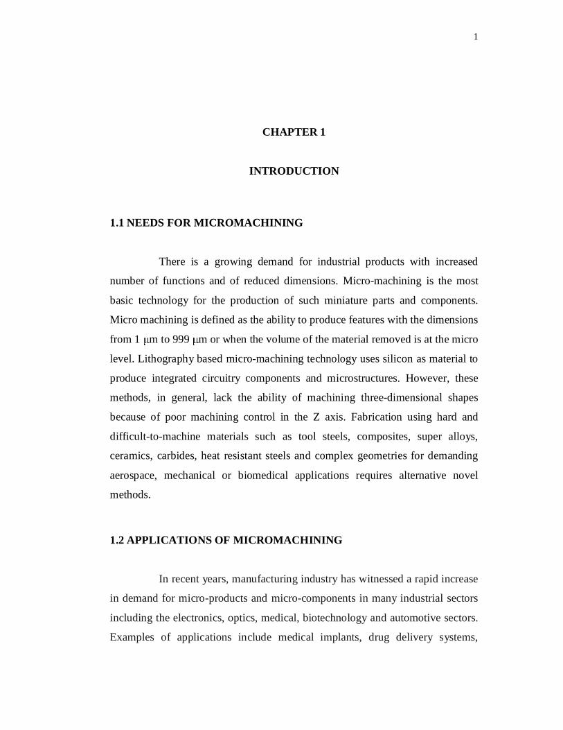
The example presented here is a micro-compressor as shown in Figure
1.1. It is a two-and-a-half dimensional structure, machined on the tip of a 1-mm
diameter cylinder. The Materials used for electrode and work-piece are tungsten
carbide and stainless steel, respectively. The centre hole with diameter 0.3 mm is
micro-EDM drilled directly with a purchased electrode. The blades are micro-
EDM milled with the same tool after it is reduced to a diameter of 40 m by
WEDG. The incremental depth for each micro-EDM milling layer is 0.5 m. All
the blades show good consistency, and the examined shape accuracy is less than
1 m. Furthermore, no taper angle and obvious path mark on the side wall of the
blades is observed.
3
Figure 1.1 A micro-compressor on a Ø1 mm cylinder: top and detail views(Liu et al.(2010))
1.2.2 Production of Micro-Turbine Impeller
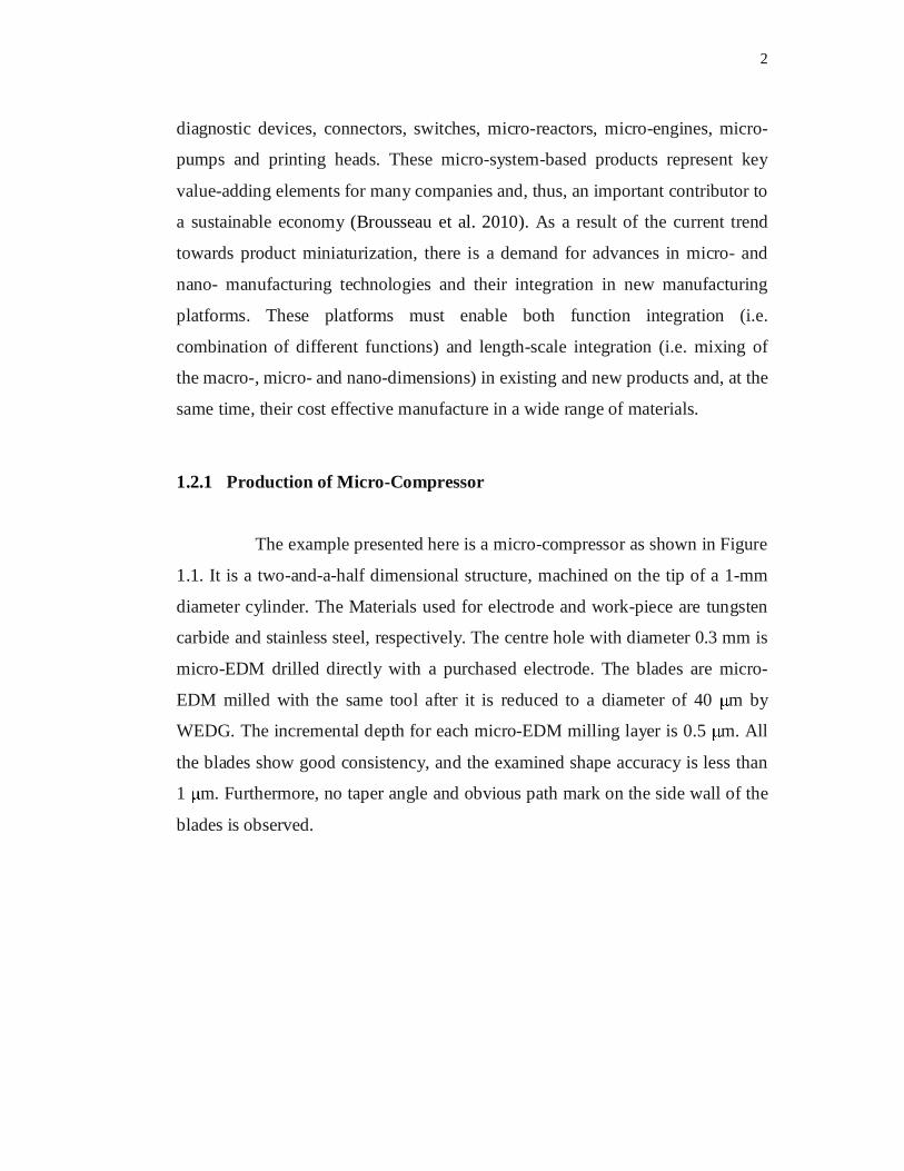
Another application example is micro-EDM milling of Si3N4-TiN
ceramic composite into a miniature three dimensional gas turbine impeller which
serves as a key component for a micro power generation system. A close view of
the manufacturing process is illustrated in Figure 1.2. The milling of each cavity
starts with a Ø1mm WC tool for pocketing using the roughing regime to remove
the bulk of the material, then followed by a Ø 0.7 mm tool for wall finishing
using the semi-finishing regime. Due to the extremely low machining speed of
the finishing regime, only two steps are performed. The same layer-by-layer
machining strategy is applied and the layer thickness for pocketing and wall
finishing are 8 and 3 m, respectively. The shape and geometrical accuracy of the
cavity is measured on a Coordinate Measuring Machine. All the machined
products show good consistency compared to the original CAD model. However,
even with rather high MRR, the total machining time for one cavity takes around
20 hours.
4
Figure 1.2 Close views of the Micro-EDM milling process and a finishedturbine impeller (Liu et al.(2010))
1.2.3 Nozzle for Diesel Fuel Injectors
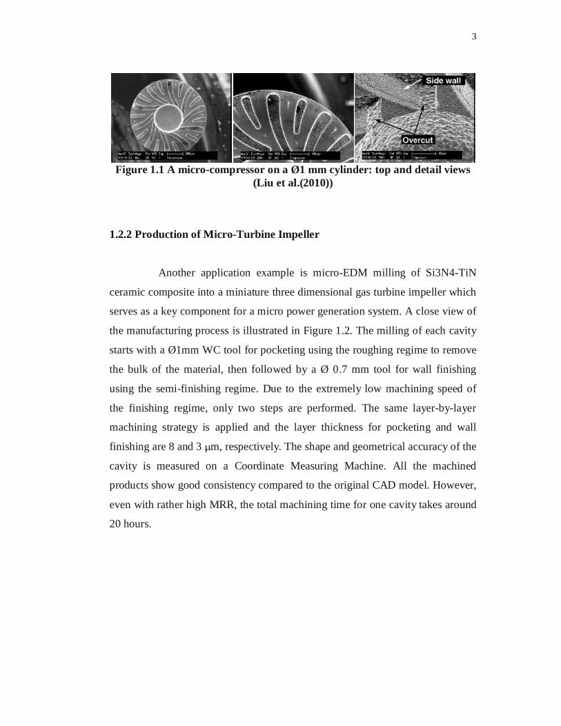
Machining capability of micro-EDM, in conductive materials with
high precision regardless of material hardness, creates a wide range of
application area with the increasing demand for miniaturized parts and
components such as holes, nozzles, and gears. Fuel injector nozzles machined by
EDM is shown in Figure 1.3.
Figure 1.3 Fuel Injection Nozzle drilling
5
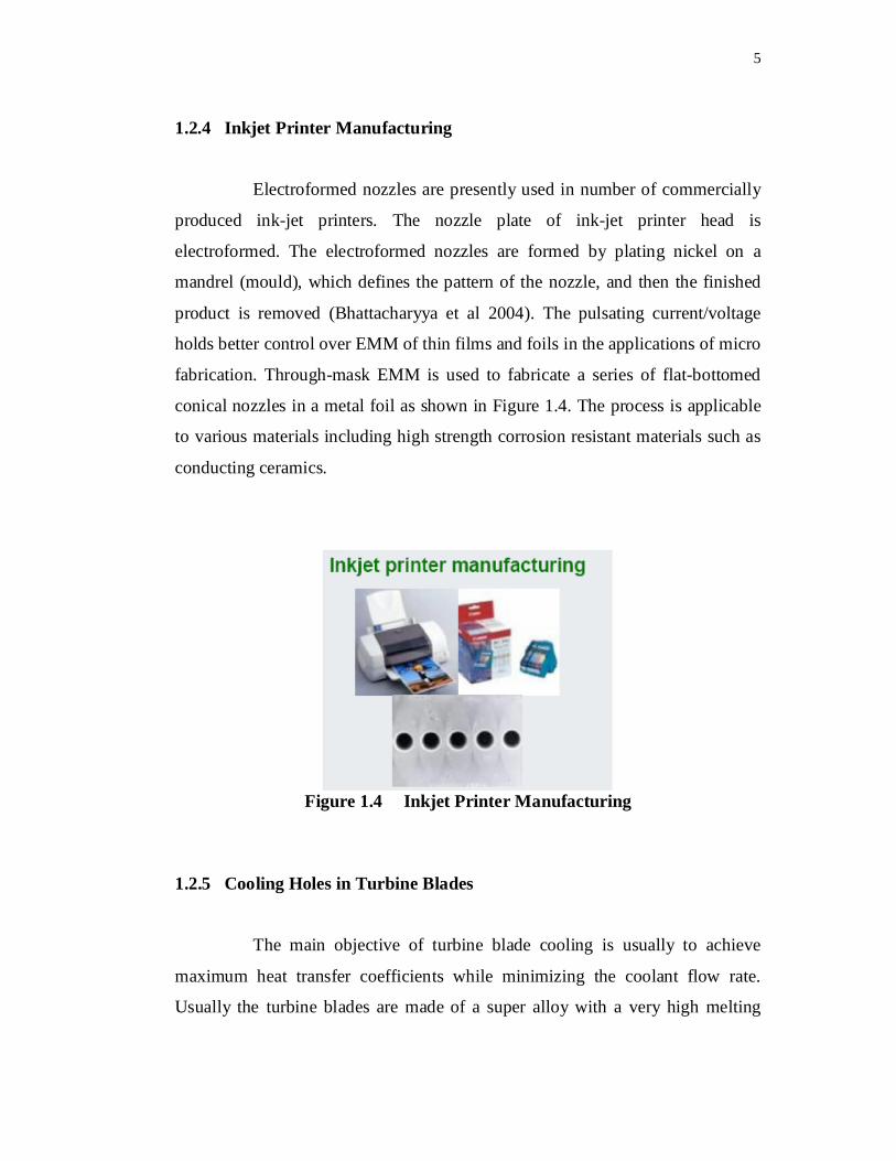
1.2.4 Inkjet Printer Manufacturing
Electroformed nozzles are presently used in number of commercially
produced ink-jet printers. The nozzle plate of ink-jet printer head is
electroformed. The electroformed nozzles are formed by plating nickel on a
mandrel (mould), which defines the pattern of the nozzle, and then the finished
product is removed (Bhattacharyya et al 2004). The pulsating current/voltage
holds better control over EMM of thin films and foils in the applications of micro
fabrication. Through-mask EMM is used to fabricate a series of flat-bottomed
conical nozzles in a metal foil as shown in Figure 1.4. The process is applicable
to various materials including high strength corrosion resistant materials such as
conducting ceramics.
Figure 1.4 Inkjet Printer Manufacturing
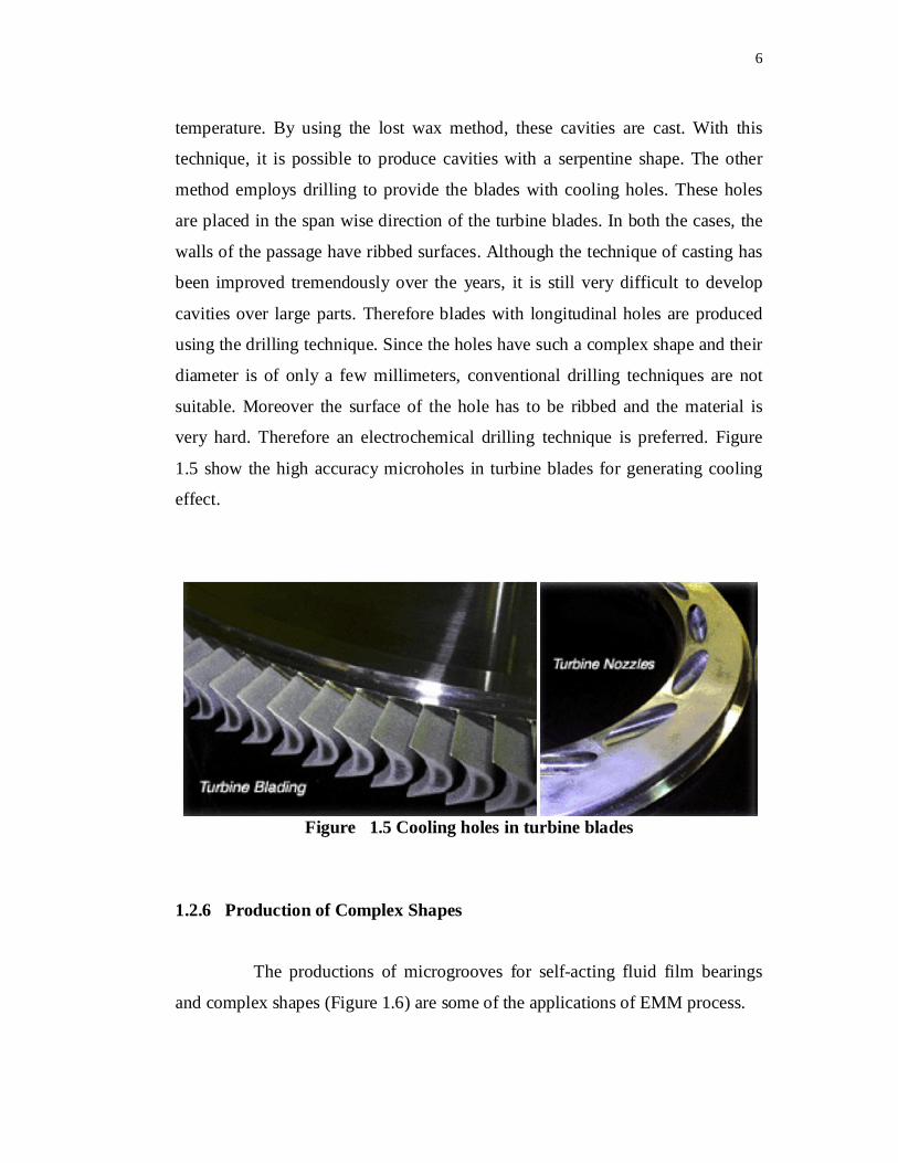
1.2.5 Cooling Holes in Turbine Blades
The main objective of turbine blade cooling is usually to achieve
maximum heat transfer coefficients while minimizing the coolant flow rate.
Usually the turbine blades are made of a super alloy with a very high melting
6
temperature. By using the lost wax method, these cavities are cast. With this
technique, it is possible to produce cavities with a serpentine shape. The other
method employs drilling to provide the blades with cooling holes. These holes
are placed in the span wise direction of the turbine blades. In both the cases, the
walls of the passage have ribbed surfaces. Although the technique of casting has
been improved tremendously over the years, it is still very difficult to develop
cavities over large parts. Therefore blades with longitudinal holes are produced
using the drilling technique. Since the holes have such a complex shape and their
diameter is of only a few millimeters, conventional drilling techniques are not
suitable. Moreover the surface of the hole has to be ribbed and the material is
very hard. Therefore an electrochemical drilling technique is preferred. Figure
1.5 show the high accuracy microholes in turbine blades for generating cooling
effect.
Figure 1.5 Cooling holes in turbine blades
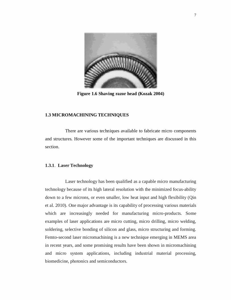
1.2.6 Production of Complex Shapes
The productions of microgrooves for self-acting fluid film bearings
and complex shapes (Figure 1.6) are some of the applications of EMM process.
7
Figure 1.6 Shaving razor head (Kozak 2004)
1.3 MICROMACHINING TECHNIQUES
There are various techniques available to fabricate micro components
and structures. However some of the important techniques are discussed in this
section.
1.3.1. Laser Technology
Laser technology has been qualified as a capable micro manufacturing
technology because of its high lateral resolution with the minimized focus-ability
down to a few microns, or even smaller, low heat input and high flexibility (Qin
et al. 2010). One major advantage is its capability of processing various materials
which are increasingly needed for manufacturing micro-products. Some
examples of laser applications are micro cutting, micro drilling, micro welding,
soldering, selective bonding of silicon and glass, micro structuring and forming.
Femto-second laser micromachining is a new technique emerging in MEMS area
in recent years, and some promising results have been shown in micromachining
and micro system applications, including industrial material processing,
biomedicine, photonics and semiconductors.
8
1.3.2 Micro-Ultrasonic Machining
Micro Ultrasonic Machining (micro-USM) is capable of making
almost any three dimensional microstructure with high aspect ratio on most of
materials, mainly on brittle materials. The USM uses a tool Ultrasonic Vibration
with combination of favorable abrasive slurry to create accurate cavities of any
shape through the impact grinding of fine grains. The machining process is non-
thermal, non-chemical, non-electrical and thus produces high quality surface
finish. However, the micro-USM is not capable of drilling of micro holes smaller
than 100 m for lack of corresponding co-axial micro tools.
1.3.3 Mechanical Micromachining
In these processes, the tools which are in direct contact with
workpiece are able to machine 2D and 3D microstructures in a variety of
materials with higher MRR than the others. Micromachining processes as
grinding, drilling, turning and milling are mechanical processes, which are not
just downscaled versions of the existing conventional processes.
1.3.4 Micro-Electrochemical Machining
Electrochemical machining (ECM) is based on the electrochemical
dissolution of a metal. In conventional ECM, the machining shape is specified by
the shape of the electrode, similar to the case of EDM or USM. However, even
when an electrolyte with very small throwing power is used, dissolution occurs in
an area wider than that facing the electrode. This characteristic is not suitable for
micromachining. However, ECM has an invaluable advantage, that is, the
machined surface is very smooth and there are no layers affected by machining.
This makes micro-ECM suitable for smoothing micro-metallic products. In order
9
to adjust the unit removal suitable for micro removal, a short pulse and a low
current are required. The low current can also be realized by using a high-
resistance electrolyte. Some trials are conducted using an electrolyte jet as the
micro tool instead of a metal tool. A high speed jet can localize electrochemical
dissolution and this enables the machining of micro indentations with controlled
dimensions by switching the current synchronously to the movement of the
workpiece. When the Scanning Tunneling Microscope (STM) technique is used
in combination with ECM, microgrooves with submicron width can be realized.
This is due to the fact that the removal in ECM is basically an atom-by-atom
phenomenon.
1.3.5 Need for Electrical Discharge Machining
Among the various competent processes EDM is considered for its
following advantages.
Used to machine any electrically conductive material regardless
of its hardness and strength.
Complex 3D micro shapes can be machined.
Short machining time.
Cost effective.
High precision can be achieved.
Versatility to machine any kind of material.
The quality of good surface finish makes this process more
attractive for drilling holes on the components exposed to high
temperature.

10
1.4 ELECTRICAL DISCHARGE MACHINING
In 1970, the English scientist, Priestley, first detected the erosive
effect of electrical discharges on metals. More recently, during research (to
eliminate erosive effects on electrical contacts) the soviet scientists, Lazarenko
and Lazarenko, decided to exploit the destructive effect of an electrical discharge
and develop a controlled method of metal machining. In 1943, they announced
the construction of the first spark erosion machining. The spark generator used in
1943, known as the Lazarenko circuit, has been employed over many years in
power supplies for EDM machines and an improved form is being used in many
current applications (Pandey et al. 2003). The EDM process can be compared
with the conventional cutting process, except that in this case, a suitably shaped
tool electrode, with a precision controlled feed movement is employed in place of
the cutting tool and the cutting energy is provided by means of short duration
electrical impulses.
The EDM has found ready application in the machining of hard metals
or alloys (necessarily electrically conductive) which cannot be machined easily
by conventional methods. It has proved valuable and effective in machining of
super tough, hard, high strength and temperature resistance of conductive
material. These metals would have been difficult to machine by conventional
methods. It thus plays a major role in the machining of dies and tools made of
tungsten carbides, stellites or hard steels. Alloys used in the aeronautics industry,
for example, hastalloy, nimonic could also be machined conveniently by this
process.The EDM is also used to machining of exotic materials, refractory metals
and hard enable steels. This process has an added advantage of being capable of
machining complicated components and making intricate shapes. Most of the
surgical components are being machined by this process since the EDM is one of
the unconventional processes which can produce better surface quality.

11
1.4.1 Principle of Electric Discharge Machining
Figure 1.7 shows the concept of EDM. Pulsed arc discharges occur in
the “gap” filled with an insulating medium, preferably a dielectric liquid like
hydrocarbon oil or de-ionized (de-mineralized) water between tool electrode and
workpiece. The insulating effect of the dielectric medium has some importance in
avoiding electrolysis effects on the electrodes during an EDM process. As the
electrode shape is copied with an offset equal to the gap-size, the liquid should be
selected to minimize the gap (10-100 m) to obtain precise machining. On the
other hand, a certain gap width is needed to avoid short circuiting, especially
when electrodes that are sensitive to vibration (like wire-electrodes) or
deformation are used. The ignition of the discharge is initiated by a high voltage,
overcoming the dielectric breakdown strength of the small gap.
A channel of plasma (ionized, electrically conductive gas with high
temperature) is formed between the electrodes and develops further with
discharge duration. As the metal removal per discharge is very small, discharges
should occur at high frequencies (103 -106 Hz). For every pulse, discharge
occurs at a single location where the electrode materials are evaporated and/or
ejected in the molten phase. As a result, a small crater is generated both on the
tool electrode and workpiece surfaces. Removed materials are cooled and
resolidified in the dielectric liquid forming several hundreds of spherical debris
particles, which are then flushed away from the gap by the dielectric flow. After
the end of the discharge duration, the temperature of the plasma and the electrode
surfaces contacting the plasma rapidly drops, resulting in a recombination of ions
and electrons and a recovery of the dielectric breakdown strength.

12
To obtain stable conditions in EDM, it is essential for the next pulse
discharge to occur at a spot distanced sufficiently far from the previous discharge
location. Such a spot may be the place where the gap is small or contaminated
with debris particles which may weaken the dielectric breakdown strength of the
liquid. Accordingly, the interval time between pulse discharges must be
sufficiently long so that the plasma generated by the previous discharge can be
deionized and the dielectric breakdown strength around the previous discharge
location can be recovered by the time the next pulse voltage is applied. Otherwise
discharges occur at the same location for every pulse, resulting in thermal
overheating and a non uniform erosion of the workpiece.
Figure 1.7 Concept of EDM (Kunieda et al. (2004))
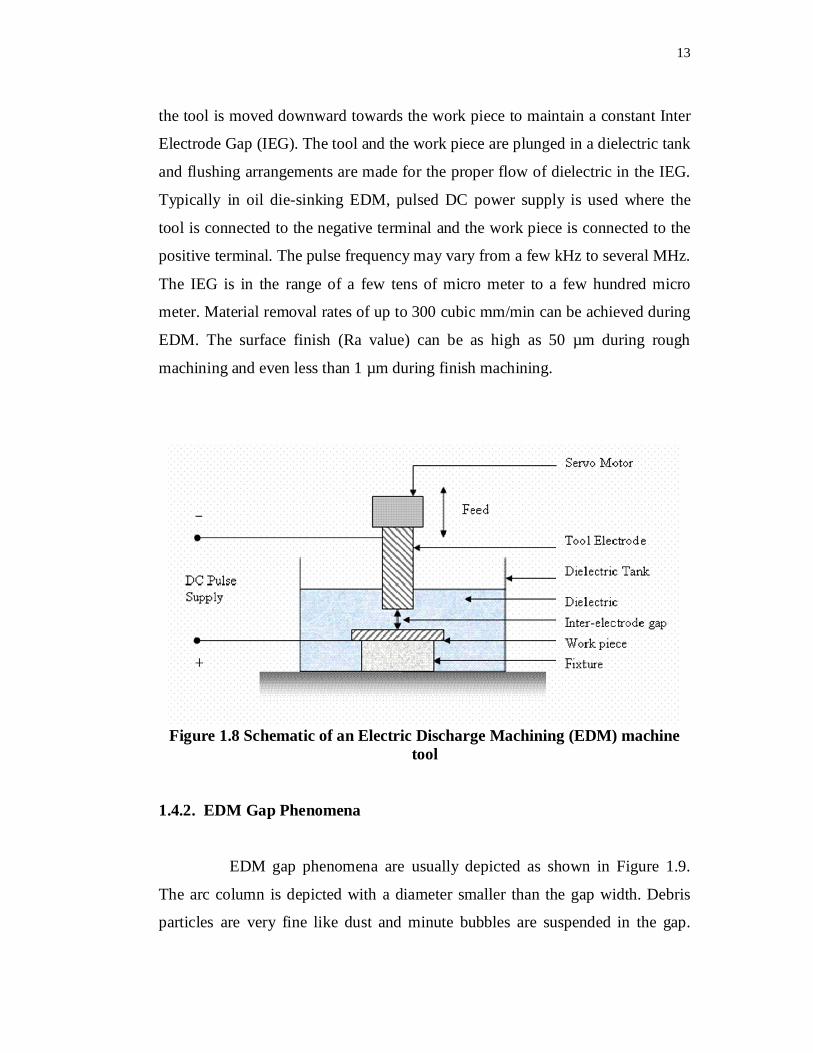
The schematic of an EDM machine tool is shown in Figure 1.8. The
tool and the work piece form the two conductive electrodes in the electric circuit.
Pulsed power is supplied to the electrodes from a separate power supply unit. The
appropriate feed motion of the tool towards the work piece is generally provided
for maintaining a constant gap distance between the tool and the work piece
during machining. This is performed by either a servo motor control or stepper
motor control of the tool holder. As material gets removed from the work piece,
13
the tool is moved downward towards the work piece to maintain a constant Inter
Electrode Gap (IEG). The tool and the work piece are plunged in a dielectric tank
and flushing arrangements are made for the proper flow of dielectric in the IEG.
Typically in oil die-sinking EDM, pulsed DC power supply is used where the
tool is connected to the negative terminal and the work piece is connected to the
positive terminal. The pulse frequency may vary from a few kHz to several MHz.
The IEG is in the range of a few tens of micro meter to a few hundred micro
meter. Material removal rates of up to 300 cubic mm/min can be achieved during
EDM. The surface finish (Ra value) can be as high as 50 µm during rough
machining and even less than 1 µm during finish machining.
Figure 1.8 Schematic of an Electric Discharge Machining (EDM) machinetool
1.4.2. EDM Gap Phenomena
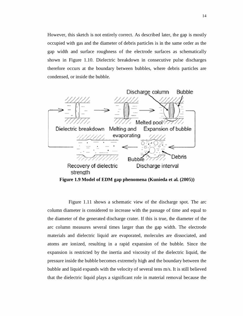
EDM gap phenomena are usually depicted as shown in Figure 1.9.
The arc column is depicted with a diameter smaller than the gap width. Debris
particles are very fine like dust and minute bubbles are suspended in the gap.
14
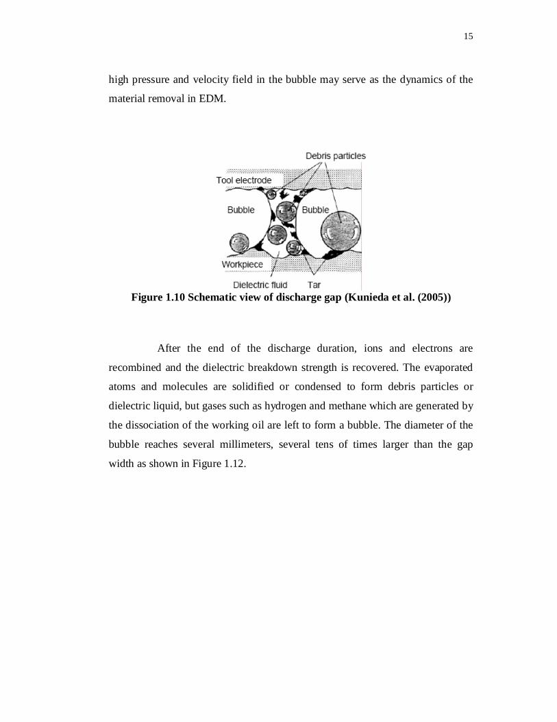
However, this sketch is not entirely correct. As described later, the gap is mostly
occupied with gas and the diameter of debris particles is in the same order as the
gap width and surface roughness of the electrode surfaces as schematically
shown in Figure 1.10. Dielectric breakdown in consecutive pulse discharges
therefore occurs at the boundary between bubbles, where debris particles are
condensed, or inside the bubble.
Figure 1.9 Model of EDM gap phenomena (Kunieda et al. (2005))
Figure 1.11 shows a schematic view of the discharge spot. The arc
column diameter is considered to increase with the passage of time and equal to
the diameter of the generated discharge crater. If this is true, the diameter of the
arc column measures several times larger than the gap width. The electrode
materials and dielectric liquid are evaporated, molecules are dissociated, and
atoms are ionized, resulting in a rapid expansion of the bubble. Since the
expansion is restricted by the inertia and viscosity of the dielectric liquid, the
pressure inside the bubble becomes extremely high and the boundary between the
bubble and liquid expands with the velocity of several tens m/s. It is still believed
that the dielectric liquid plays a significant role in material removal because the
15
high pressure and velocity field in the bubble may serve as the dynamics of the
material removal in EDM.
Figure 1.10 Schematic view of discharge gap (Kunieda et al. (2005))
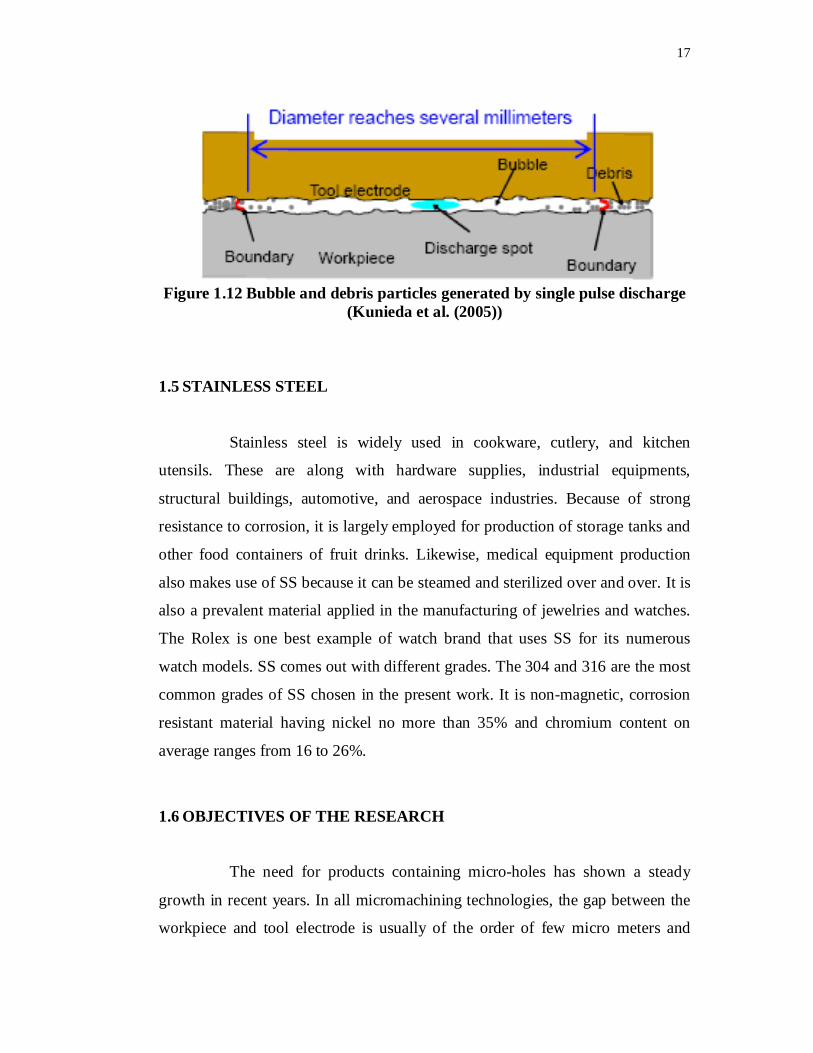
After the end of the discharge duration, ions and electrons are
recombined and the dielectric breakdown strength is recovered. The evaporated
atoms and molecules are solidified or condensed to form debris particles or
dielectric liquid, but gases such as hydrogen and methane which are generated by
the dissociation of the working oil are left to form a bubble. The diameter of the
bubble reaches several millimeters, several tens of times larger than the gap
width as shown in Figure 1.12.

16
Figure 1.11 Discharge phenomena in EDM gap (Kunieda et al. (2005))
Since pulse discharge occurs several thousand times or more per
second, obviously the gap becomes filled with gas in typical EDM processes.
Hundreds of debris particles are generated per single pulse discharge, blown off
through the bubble generated by the discharge and stopped at the boundary of the
bubble due to the viscosity of the dielectric liquid [Yoshida and Kunieda (1998)].
The melted and evaporated materials are cooled by the dielectric liquid and
solidified to form spherical debris particles. Thus debris particles are removed
from the gap with the dielectric liquid and not reattached on the electrode
surfaces. Furthermore, heat convection in the boundary layers of the dielectric
liquid cools the electrode surfaces, resulting in machining stability. Thus, the
dielectric liquid plays another important role in flushing debris particles and
cooling of the gap.
17
Figure 1.12 Bubble and debris particles generated by single pulse discharge(Kunieda et al. (2005))
1.5 STAINLESS STEEL
Stainless steel is widely used in cookware, cutlery, and kitchen
utensils. These are along with hardware supplies, industrial equipments,
structural buildings, automotive, and aerospace industries. Because of strong
resistance to corrosion, it is largely employed for production of storage tanks and
other food containers of fruit drinks. Likewise, medical equipment production
also makes use of SS because it can be steamed and sterilized over and over. It is
also a prevalent material applied in the manufacturing of jewelries and watches.
The Rolex is one best example of watch brand that uses SS for its numerous
watch models. SS comes out with different grades. The 304 and 316 are the most
common grades of SS chosen in the present work. It is non-magnetic, corrosion
resistant material having nickel no more than 35% and chromium content on
average ranges from 16 to 26%.
1.6 OBJECTIVES OF THE RESEARCH
The need for products containing micro-holes has shown a steady
growth in recent years. In all micromachining technologies, the gap between the
workpiece and tool electrode is usually of the order of few micro meters and

18
removal of debris particles from such a small gap has been a challenge. This
research aims to alleviate the problem of flushing of debris by machining micro
holes using conventional EDM. In conventional EDM machine rotary brass
hollow tubular electrode is fed downward into the workpiece under servo control
in which the removal of debris is easier. The quality of the hole produced by this
rotary EDM is superior owing to the improvement in flushing, and reduction in
tool wear.
In this research, two commercially available machines have been
considered for conducting the experiments in order to reveal the machining
characteristics and predict the machined shape of holes. The optimization of
process parameters is essential to achieve of high responsiveness in production,
and is crucial to dynamically changing market conditions. Taguchi Technique
and Grey relational theory have been considered to get optimization of process
parameters. Since they provide a significant reduction in the number of
experiments thereby speeding up the experimental process. Experiments are
conducted using EDM to drill micro-holes on SS 304 and SS 316 in the view of
maximizing the Material Removal Rate (MRR), and minimizing Tool Wear Rate
(TWR), Overcut (OC) and Taper (T) individually and simultaneously.
In order to achieve this aim, the following objectives have been
framed.
To compare the performance of a micro hole produced in EDM
with the micro-EDM.
To optimize the process parameters using Taguchi technique for
single objective optimization.
To optimize the process parameters using Grey Relational
Analysis for Multiple objective optimization.

19
1.7 ORGANIZATION OF THE THESIS
Chapter1 presents the Introduction and objectives of the research.
Chapter 2 presents a literature review of EDM process describing the
machining performance, micro-hole machining by varying EDM specifications
and process optimization.
Chapter 3 presents the experimental investigation of micro-electrode
preparation and micro-hole drilling using micro-EDM machine followed by EDX
analysis of machined micro-holes.
Chapter 4 includes the details of experimental setups,specifications
and planning of experiments.
Chapter 5 explains the experiments conducted on EDM machine and
optimization by using Taguchi method for SS 304.
Chapter 6 describes the optimization of machining parameters of SS
304 by using Grey Relational Analysis followed by the SEM analysis of micro-
holes.
Chapter 7 describes the optimization of machining parameters of SS
316 by using Grey Relational Analysis followed by the confirmation test and
Analysis based on SEM Micrographs.
Chapter 8 presents a summary of the major contributions from this
research and recommendations for future research.