Embed Size (px)
Citation preview
1
CHAPTER 1
INTRODUCTION
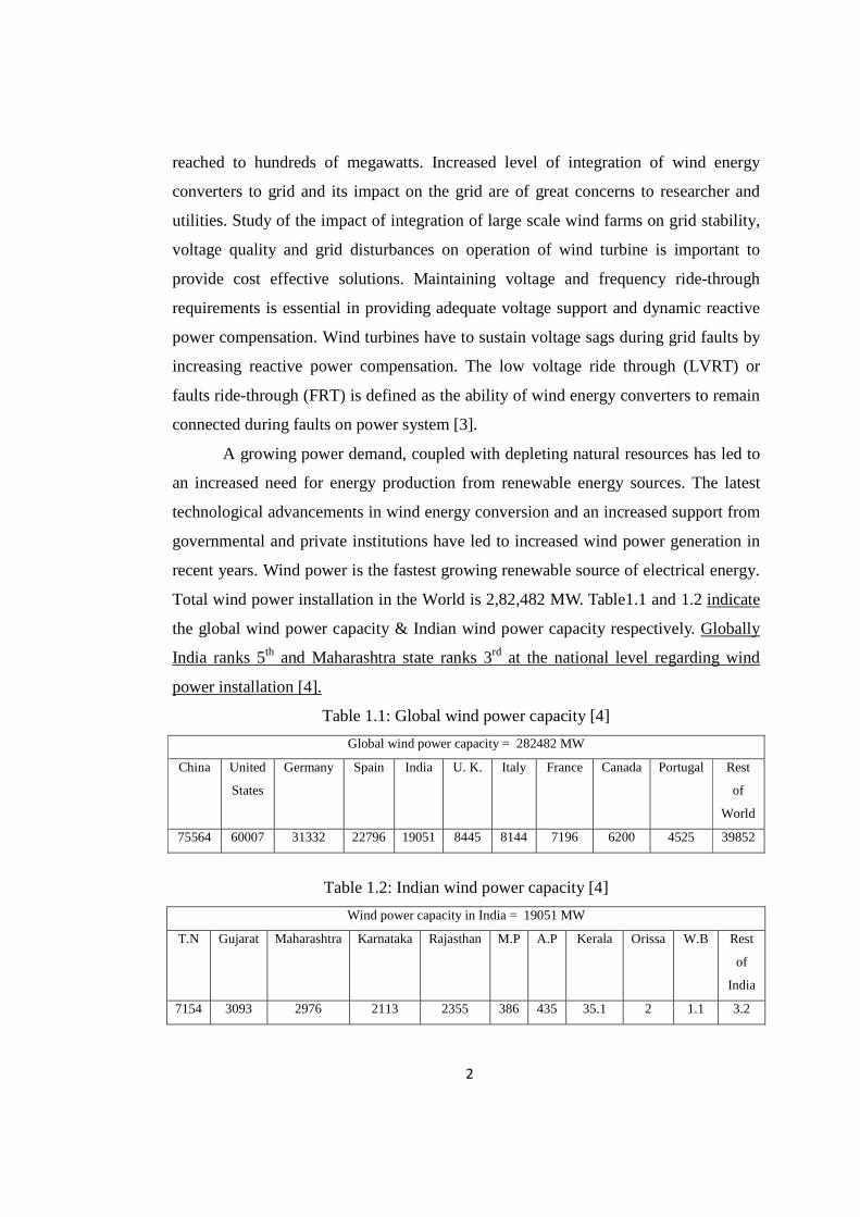
1.1: Background of wind energy
Windmills have been used for at least 3000 years, mainly for grinding grain or
pumping water, while in sailing ships, the wind has been an essential source of power
for even longer. From as early as the thirteenth century, horizontal-axis windmills
were an integral part of the rural economy and only fell into disuse with the advent of
cheap fossil-fuelled engines and then the spread of rural electrification. To use wind
energy efficiently and to concentrate the visual impact of modem wind turbines, the
regions with a good wind climate, a tendency to group turbines in wind farms can be
observed. These wind farms are connected to high voltage transmission grids and thus
directly influence the dynamic behavior of the electrical power system [1].
Modern electricity-generating wind turbines now use a three-bladed upwind
rotor, although two-bladed, and even one-bladed, rotors were used in earlier
commercial turbines. Reducing the number of blades means that the rotor has to
operate at a higher rotational speed in order to extract the wind energy from wind
turbines. Initially, these turbines were small, sometimes rated at only 30 kW, but were
developed over the next 15 years to around 40-m diameter, 800–1,000 kW. However,
by the mid-1990s, it was becoming clear that for large wind turbines it would be
necessary to move away from this simple architecture and to use a number of the
advanced concepts (e.g. variable-speed operation, pitch regulation, advanced
materials) that had been investigated in the earlier research work. Large wind turbines
up to 100 m in rotor diameter with rated capacity at 3–4 MW are used. Most of the
largest wind turbines now being installed to operate at variable-speed, as the power
electronic converters also allow much greater control of the output power and it is
easier to comply with the requirements of the power system network operator [2].
In the past, wind power plants were with smaller sizes and usually in the range
of tens of megawatts per wind farm. With the increase of the turbine capacity and the
number of turbines connected to the grid at the substation, the wind farm capacity
2
reached to hundreds of megawatts. Increased level of integration of wind energy
converters to grid and its impact on the grid are of great concerns to researcher and
utilities. Study of the impact of integration of large scale wind farms on grid stability,
voltage quality and grid disturbances on operation of wind turbine is important to
provide cost effective solutions. Maintaining voltage and frequency ride-through
requirements is essential in providing adequate voltage support and dynamic reactive
power compensation. Wind turbines have to sustain voltage sags during grid faults by
increasing reactive power compensation. The low voltage ride through (LVRT) or
faults ride-through (FRT) is defined as the ability of wind energy converters to remain
connected during faults on power system [3].
A growing power demand, coupled with depleting natural resources has led to
an increased need for energy production from renewable energy sources. The latest
technological advancements in wind energy conversion and an increased support from
governmental and private institutions have led to increased wind power generation in
recent years. Wind power is the fastest growing renewable source of electrical energy.
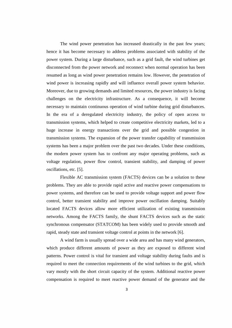
Total wind power installation in the World is 2,82,482 MW. Table1.1 and 1.2 indicate
the global wind power capacity & Indian wind power capacity respectively. Globally
India ranks 5th and Maharashtra state ranks 3rd at the national level regarding wind
power installation [4].
Table 1.1: Global wind power capacity [4]
Global wind power capacity = 282482 MW
China United
States
Germany Spain India U. K. Italy France Canada Portugal Rest
of
World
75564 60007 31332 22796 19051 8445 8144 7196 6200 4525 39852
Table 1.2: Indian wind power capacity [4]
Wind power capacity in India = 19051 MW
T.N Gujarat Maharashtra Karnataka Rajasthan M.P A.P Kerala Orissa W.B Rest
of
India
7154 3093 2976 2113 2355 386 435 35.1 2 1.1 3.2
3
The wind power penetration has increased drastically in the past few years;
hence it has become necessary to address problems associated with stability of the
power system. During a large disturbance, such as a grid fault, the wind turbines get
disconnected from the power network and reconnect when normal operation has been
resumed as long as wind power penetration remains low. However, the penetration of
wind power is increasing rapidly and will influence overall power system behavior.
Moreover, due to growing demands and limited resources, the power industry is facing
challenges on the electricity infrastructure. As a consequence, it will become
necessary to maintain continuous operation of wind turbine during grid disturbances.
In the era of a deregulated electricity industry, the policy of open access to
transmission systems, which helped to create competitive electricity markets, led to a
huge increase in energy transactions over the grid and possible congestion in
transmission systems. The expansion of the power transfer capability of transmission
systems has been a major problem over the past two decades. Under these conditions,
the modern power system has to confront any major operating problems, such as
voltage regulation, power flow control, transient stability, and damping of power
oscillations, etc. [5].
Flexible AC transmission system (FACTS) devices can be a solution to these
problems. They are able to provide rapid active and reactive power compensations to
power systems, and therefore can be used to provide voltage support and power flow
control, better transient stability and improve power oscillation damping. Suitably
located FACTS devices allow more efficient utilization of existing transmission
networks. Among the FACTS family, the shunt FACTS devices such as the static
synchronous compensator (STATCOM) has been widely used to provide smooth and
rapid, steady state and transient voltage control at points in the network [6].
A wind farm is usually spread over a wide area and has many wind generators,
which produce different amounts of power as they are exposed to different wind
patterns. Power control is vital for transient and voltage stability during faults and is
required to meet the connection requirements of the wind turbines to the grid, which
vary mostly with the short circuit capacity of the system. Additional reactive power
compensation is required to meet reactive power demand of the generator and the
4
matching transformers during fault conditions to avoid voltage collapse. Low voltage
ride through (LVRT) system is a recently introduced requirement that transmission
operators demand from wind farms. A STATCOM is being evaluated for its
performance to effectively provide LVRT for wind turbines in a wind farm. This
thesis explores the possibility of enabling wind farms to provide voltage support
during normal conditions, as well as under conditions when system voltages are not
within desired limits. The transient behavior of wind farms can be improved by
injecting large amounts of reactive power during a fault. This thesis examines the use
of STATCOM in wind farms to stabilize the grid voltage after grid disturbances such
as severe system faults.
The wind turbines (WTs) considered in this thesis are singly fed induction
generator (SFIG) or squirrel cage induction generator (SCIG), doubly/double fed
induction generator (DFIG) or wound rotor induction generator (WRIG) also
electrically excited synchronous generator (EESG). In this thesis, a combined case
study of three interconnected types of wind energy converter with STATCOM and
with linear & nonlinear load connected to the grid is carried out to study the impact of
mentioned factors and provide a cost effective solution.
1.2: Wind turbine concepts and generator types
To understand the wind energy, it is important to learn wind turbines. Wind
turbines can be categorized according to the axis of rotation: vertical and horizontal
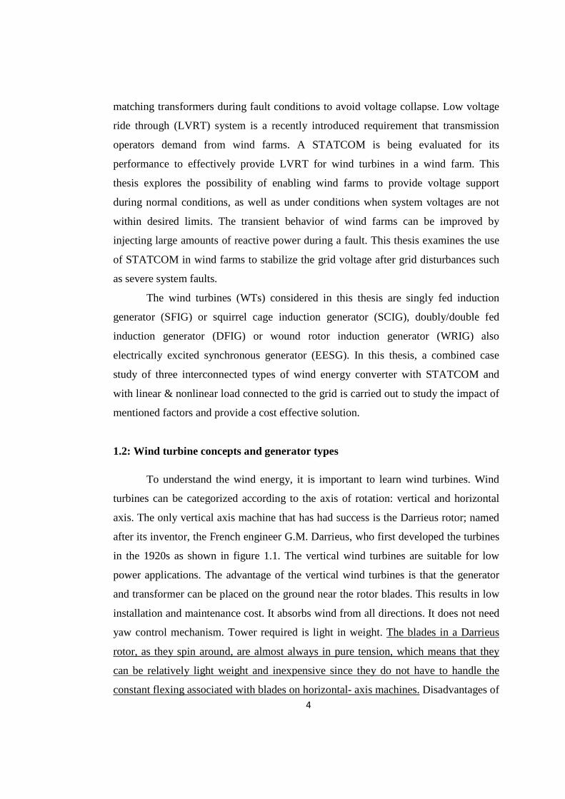
axis. The only vertical axis machine that has had success is the Darrieus rotor; named
after its inventor, the French engineer G.M. Darrieus, who first developed the turbines
in the 1920s as shown in figure 1.1. The vertical wind turbines are suitable for low
power applications. The advantage of the vertical wind turbines is that the generator
and transformer can be placed on the ground near the rotor blades. This results in low
installation and maintenance cost. It absorbs wind from all directions. It does not need
yaw control mechanism. Tower required is light in weight. The blades in a Darrieus
rotor, as they spin around, are almost always in pure tension, which means that they
can be relatively light weight and inexpensive since they do not have to handle the
constant flexing associated with blades on horizontal- axis machines. Disadvantages of
5
vertical axis wind turbine (VAWT) are that blades are close to ground where wind
speed is low. Wind near the surface of earth is not only slower, but also more turbulent
which increases stress on VAWT. At low speeds, it has a very little starting torque and
high speed, output power cannot be controlled as pitch control is not provided. The
power efficiency is limited to 25% [7].
Figure 1.1: Darrieus wind turbine [8]
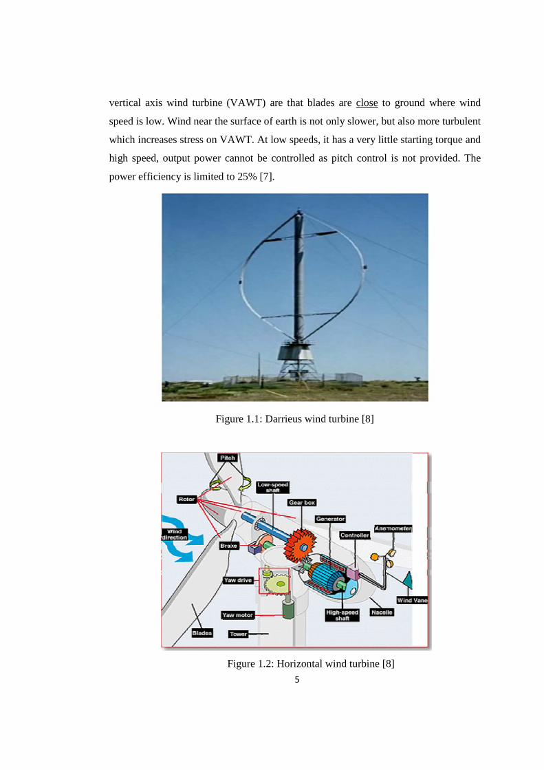
Figure 1.2: Horizontal wind turbine [8]
6
Most popular types of wind turbine is horizontal axis wind turbines (HAWT)
as shown in figure 1.2. Similar to the vertical wind turbines, the horizontal wind
turbines can be built with two or three blades. Wind turbines have a control system
that controls the speed of the rotor blades. The anemometer measures the wind speed
and transmits the data to the controller. The pitch angle of the rotor blades is
controlled by the controller to attain the maximum wind power and to limit the
mechanical power in the case of the strong wind. The rotor blades are pitched to
decrease the angle of attack from the wind when the rated power is reached. The yaw
drive can turn the wind turbine compartment or so called the nacelle according to the
direction of the wind measured by the wind vane [8].
In addition to the pitch control, the maximum power from the wind can be
limited by passive stall control for small and medium-size wind turbines. The stall
control avoids the rotation of the blades. Contrarily to the pitch-angle control, passive
stall control has fixed pitch-angle rotor blades. The passive stall control relates to the
design of the rotor blades that leads to turbulence or so called stall on the back of the
blades to reduce the power extracted from the wind. As the capacity of wind turbines
increases, active stall control is used for large wind turbines, with rating above 1 MW.
The active stall control is similar to the pitch-angle control. The rotor blades are
rotated to obtain the maximum power extract. When the extracted power reaches the
rated power, opposite to the pitch-angle control, the active stall control turns the rotor
blades to increase the angle of attack from the wind to provoke the turbulence.
Disadvantages of HAWT are that tower shadow effect exists because every time a
blade swing behind the tower, it encounters a brief period of reduced wind which
causes the blade to flex. It increases blade noise [9].
The development of modern wind power conversion technology has been
going on since 1970s, and the rapid development has been seen from 1990s. Various
wind turbine concepts have been developed and different wind generators have been
built. Referring to the rotation speed, wind turbine concepts can be classified into
fixed speed, limited variable speed concept with a partial-scale power converter and
variable speed concept with a full-scale power converter.
7
There are different types of generators, which are in use by the wind turbines
to generate electricity. These generators can be classified by different aspects such as
with respect to speed, i.e. constant speed or variable speed, with respect to working
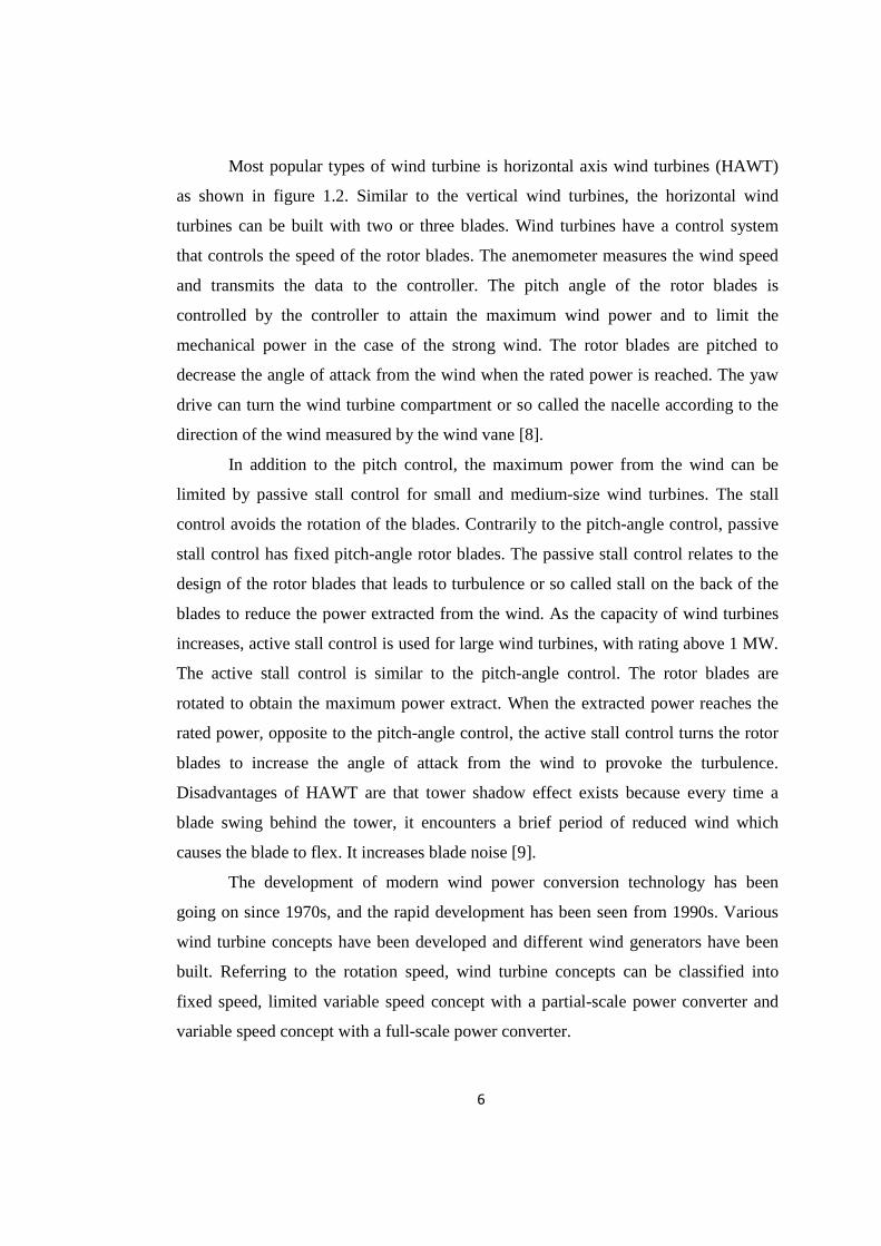
principle, i.e. with or without a power electronic converter. Figure 1.3 shows the
classification of generators.
Figure 1.3: Classification of generators
Three types of typical generator systems for large wind turbines exist. The first
type is a constant speed or fixed-speed wind turbine system using a multi-stage
gearbox and a standard squirrel-cage or singly fed induction generator (SCIG),
directly connected to the grid. The second type is a variable speed wind turbine system
with a multi-stage gearbox and a doubly fed induction generator (DFIG), where the
power is fed into the grid from stator as well as a rotor. The third type is also a
variable speed wind turbine, but it is a gearless wind turbine system with a direct-drive
generator, normally a low-speed, high-torque synchronous generator and a full-scale
power electronic converter are used [9].
1.2.1: Fixed (Constant) speed concept
This configuration is known as the singly fed induction generator concept
(SFIG concept). The fixed speed wind generator systems have been used with a
multiple-stage gearbox and a SCIG directly connected to the grid through a
Wind Generating
System
Variable Speed
Turbine
Doubly Fed Induction Generator
Direct Drive Synchronous
Generator
Constant Speed
Turbine
Singly Fed Induction Generator
8
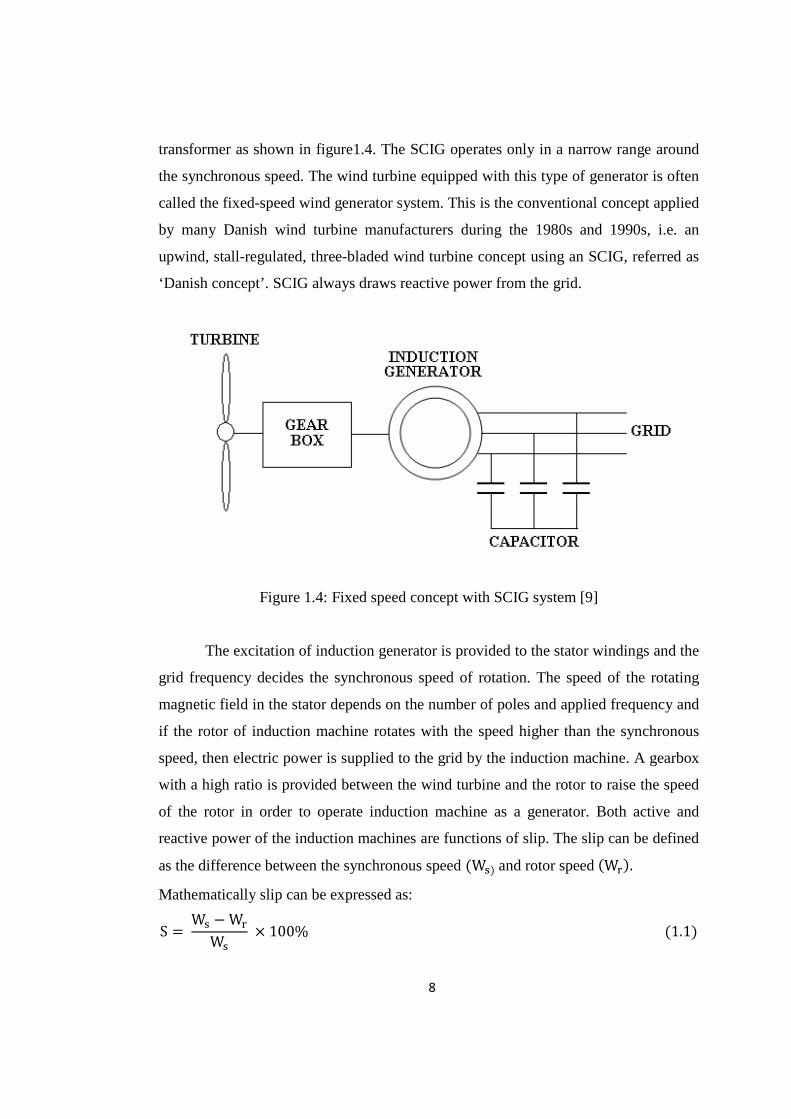
transformer as shown in figure1.4. The SCIG operates only in a narrow range around
the synchronous speed. The wind turbine equipped with this type of generator is often
called the fixed-speed wind generator system. This is the conventional concept applied
by many Danish wind turbine manufacturers during the 1980s and 1990s, i.e. an
upwind, stall-regulated, three-bladed wind turbine concept using an SCIG, referred as
‘Danish concept’. SCIG always draws reactive power from the grid.
Figure 1.4: Fixed speed concept with SCIG system [9]
The excitation of induction generator is provided to the stator windings and the
grid frequency decides the synchronous speed of rotation. The speed of the rotating
magnetic field in the stator depends on the number of poles and applied frequency and
if the rotor of induction machine rotates with the speed higher than the synchronous
speed, then electric power is supplied to the grid by the induction machine. A gearbox
with a high ratio is provided between the wind turbine and the rotor to raise the speed
of the rotor in order to operate induction machine as a generator. Both active and
reactive power of the induction machines are functions of slip. The slip can be defined
as the difference between the synchronous speed �W��and rotor speed�W��.
Mathematically slip can be expressed as:
S W� �W�
W�� 100%�1.1�
9
When the slip is negative, the induction machine supplies the active power and
operates as a generator. When the slip is positive, the induction machine consumes the
active power and it operates as a motor. Reactive power is consumed at both positive
and negative slip operation.
The well-known advantages of SCIG are that they are robust, relatively cheap for
mass production. In addition, it enables stall-regulated machines to operate at a
constant speed when it is connected to a large grid, which provides a stable control
frequency. Although the stall control method is usually used in combination with the
fixed speed SCIG for power control, the active stall control or pitch control have also
been applied.
Disadvantages of SCIG for the fixed speed wind turbine concept are as follows:
� The speed is not controllable and variable only over a very narrow range. The
fixed speed concept means that wind speed fluctuations are directly translated
into electromechanical torque variations, this causes high mechanical and
fatigue stresses on the system (turbine blades, gearbox and generator) and may
result in swing oscillations between turbine and generator shaft. The periodical
torque dips because of the tower shadow and shear effect are not damped by
speed variations and result in higher flicker. Furthermore, the turbine speed
cannot be adjusted with the wind speed to optimize the aerodynamic
efficiency. Although a pole-changeable SCIG has been used in some
commercial wind turbines, it does not provide continuous speed variations.
� A three-stage gearbox in the drive train is necessary for this wind turbine
concept. Gearboxes represent a large mass in the nacelle, and also a large
fraction of the investment costs.
� It is necessary to obtain the excitation current from the stator terminal of
SCIG. This makes it impossible to support grid voltage control.
� The induction generator is excited by the grid and consumes reactive power;
hence the power factor is less than one and cannot be controlled.
� The speed cannot be controlled either [9].
10
1.2.2: Limited variable speed concept with a partial-scale power converter
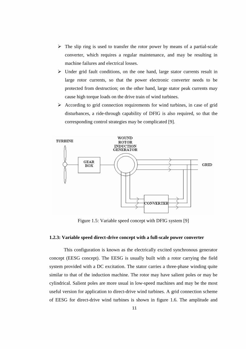
This configuration is known as the doubly fed induction generator concept
(DFIG concept), which corresponds to a variable speed wind turbine with a WRIG and
a partial-scale power converter on the rotor circuit, as shown in figure 1.5. The
induction machine used for power generation is a wound type construction. It has two
windings, one in the stator and one on the rotor (squirrel cage rotor has copper bars
instead of windings on it). The stator windings are connected directly to the network.
The rotor windings are also connected to the grid via a frequency converter by means
of slip rings. When the stator is excited, a rotating magnetic field is produced. The
speed of the rotating magnetic field depends on the system frequency and the number
of poles. The mechanical power captured from the wind is converted into electrical
power. This electrical power is fed into the grid by both stator and rotor windings.
Since the power in the rotor circuit is at a different frequency, which differs from the
network frequency and is a function of generator slip. The output of rotor circuit is
first converted into a DC quantity and again converted into an AC quantity with grid
frequency. A gearbox is provided between the rotor and the generator to adopt the
speed of the induction generator.
The stator is directly connected to the grid, whereas the rotor is connected through
a power electronic converter. The power converter controls the rotor frequency and
thus the rotor speed. This concept supports a wide speed range operation, depending
on the size of the frequency converter. Typically, the variable speed range is ± 30%
around the synchronous speed. The rating of the power electronic converter is only 25
to 30% of the generating capacity, which makes this concept attractive and popular
from an economic point of view.
DFIG system has the following disadvantages:
� A multi-stage gearbox is still necessary in the drive train because the speed
range for DFIG is far from a common turbine speed of 10 to 25 RPM. A
gearbox is inevitable to have some drawbacks, such as heat dissipation from
friction, regular maintenance and audible noise.
11
� The slip ring is used to transfer the rotor power by means of a partial-scale
converter, which requires a regular maintenance, and may be resulting in
machine failures and electrical losses.
� Under grid fault conditions, on the one hand, large stator currents result in
large rotor currents, so that the power electronic converter needs to be
protected from destruction; on the other hand, large stator peak currents may
cause high torque loads on the drive train of wind turbines.
� According to grid connection requirements for wind turbines, in case of grid
disturbances, a ride-through capability of DFIG is also required, so that the
corresponding control strategies may be complicated [9].
Figure 1.5: Variable speed concept with DFIG system [9]
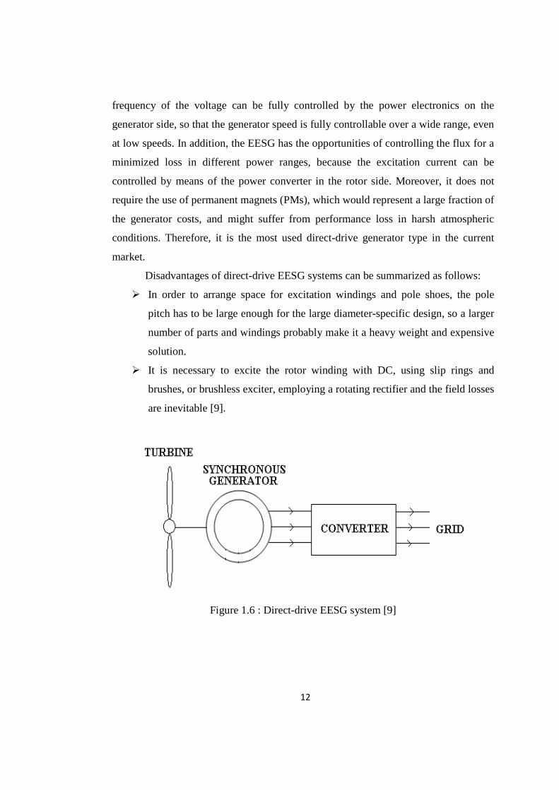
1.2.3: Variable speed direct-drive concept with a full-scale power converter
This configuration is known as the electrically excited synchronous generator
concept (EESG concept). The EESG is usually built with a rotor carrying the field
system provided with a DC excitation. The stator carries a three-phase winding quite
similar to that of the induction machine. The rotor may have salient poles or may be
cylindrical. Salient poles are more usual in low-speed machines and may be the most
useful version for application to direct-drive wind turbines. A grid connection scheme
of EESG for direct-drive wind turbines is shown in figure 1.6. The amplitude and
12
frequency of the voltage can be fully controlled by the power electronics on the
generator side, so that the generator speed is fully controllable over a wide range, even
at low speeds. In addition, the EESG has the opportunities of controlling the flux for a
minimized loss in different power ranges, because the excitation current can be
controlled by means of the power converter in the rotor side. Moreover, it does not
require the use of permanent magnets (PMs), which would represent a large fraction of
the generator costs, and might suffer from performance loss in harsh atmospheric
conditions. Therefore, it is the most used direct-drive generator type in the current
market.
Disadvantages of direct-drive EESG systems can be summarized as follows:
� In order to arrange space for excitation windings and pole shoes, the pole
pitch has to be large enough for the large diameter-specific design, so a larger
number of parts and windings probably make it a heavy weight and expensive
solution.
� It is necessary to excite the rotor winding with DC, using slip rings and
brushes, or brushless exciter, employing a rotating rectifier and the field losses
are inevitable [9].
Figure 1.6 : Direct-drive EESG system [9]
13
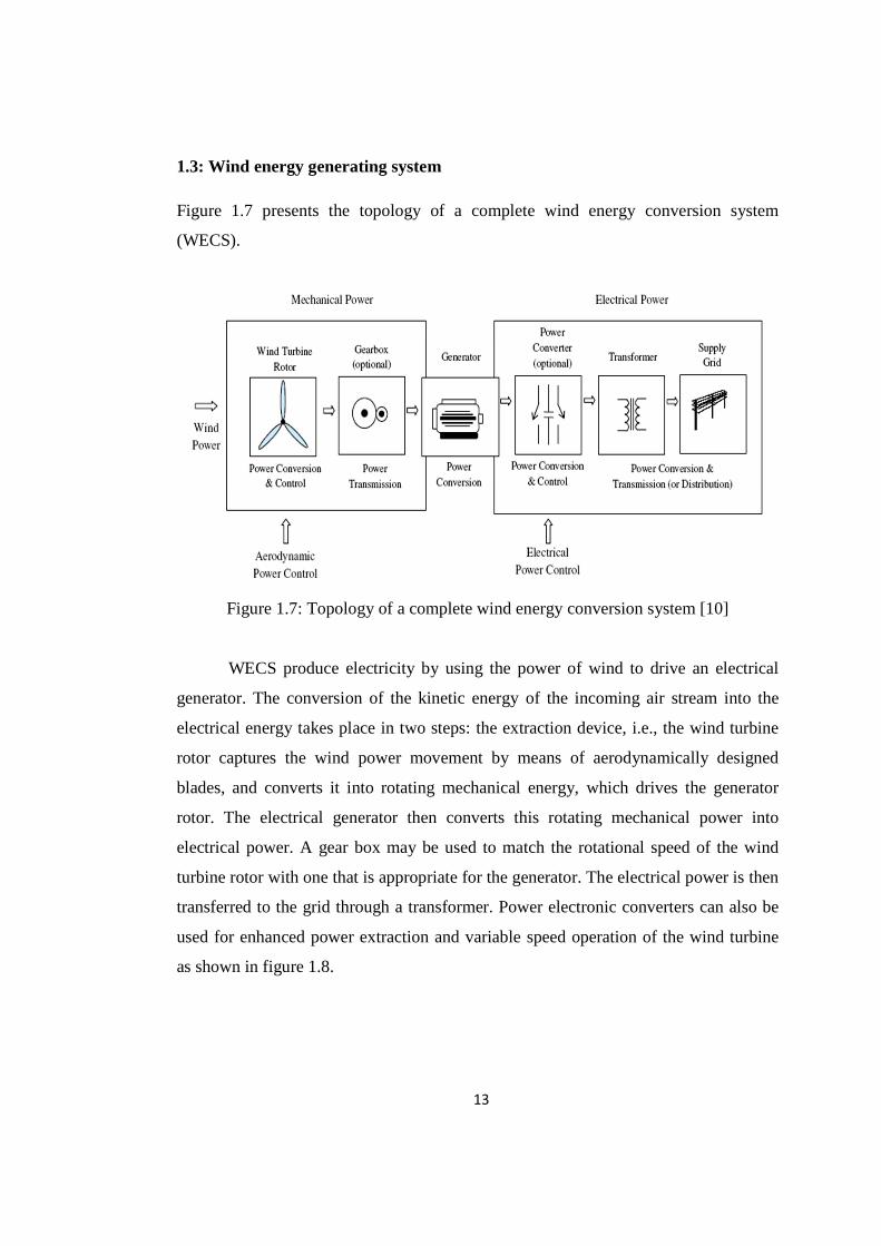
1.3: Wind energy generating system
Figure 1.7 presents the topology of a complete wind energy conversion system
(WECS).
Figure 1.7: Topology of a complete wind energy conversion system [10]
WECS produce electricity by using the power of wind to drive an electrical
generator. The conversion of the kinetic energy of the incoming air stream into the
electrical energy takes place in two steps: the extraction device, i.e., the wind turbine
rotor captures the wind power movement by means of aerodynamically designed
blades, and converts it into rotating mechanical energy, which drives the generator
rotor. The electrical generator then converts this rotating mechanical power into
electrical power. A gear box may be used to match the rotational speed of the wind
turbine rotor with one that is appropriate for the generator. The electrical power is then
transferred to the grid through a transformer. Power electronic converters can also be
used for enhanced power extraction and variable speed operation of the wind turbine
as shown in figure 1.8.
14
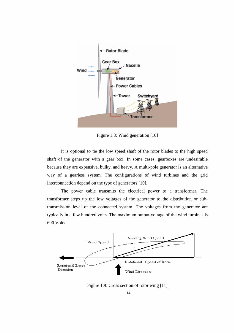
Figure 1.8: Wind generation [10]
It is optional to tie the low speed shaft of the rotor blades to the high speed
shaft of the generator with a gear box. In some cases, gearboxes are undesirable
because they are expensive, bulky, and heavy. A multi-pole generator is an alternative
way of a gearless system. The configurations of wind turbines and the grid
interconnection depend on the type of generators [10].
The power cable transmits the electrical power to a transformer. The
transformer steps up the low voltages of the generator to the distribution or sub-
transmission level of the connected system. The voltages from the generator are
typically in a few hundred volts. The maximum output voltage of the wind turbines is
690 Volts.
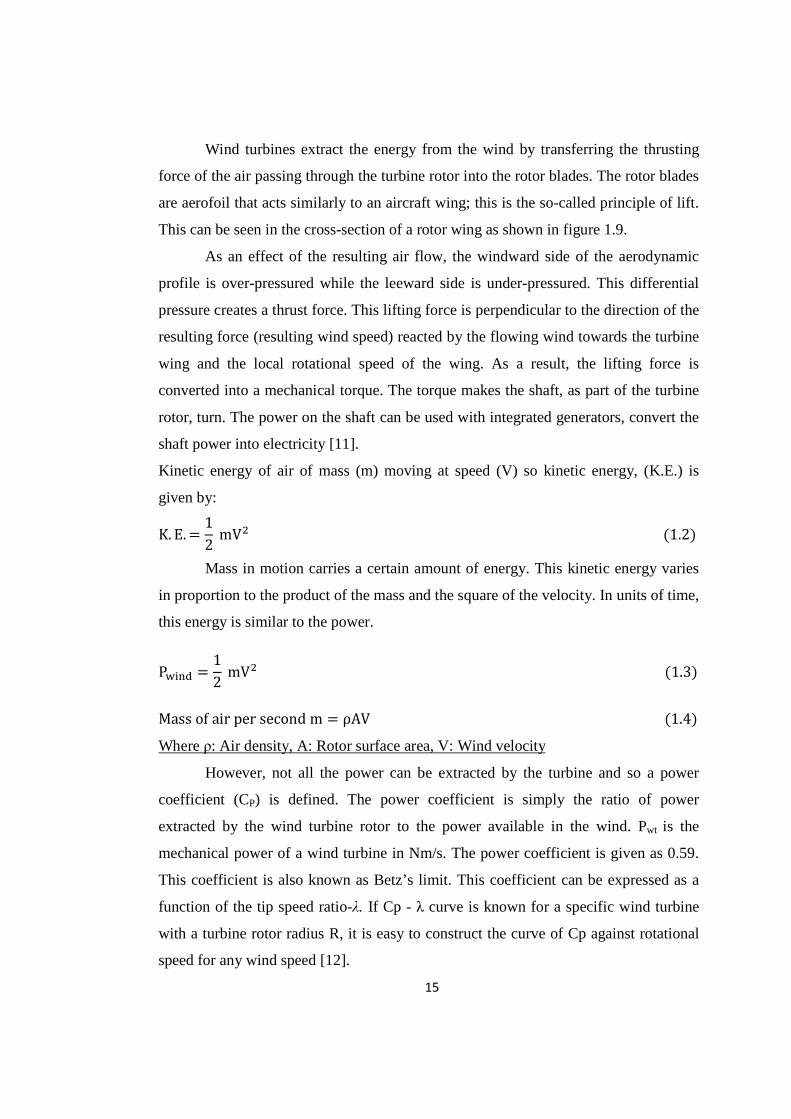
Figure 1.9: Cross section of rotor wing [11]
15
Wind turbines extract the energy from the wind by transferring the thrusting
force of the air passing through the turbine rotor into the rotor blades. The rotor blades
are aerofoil that acts similarly to an aircraft wing; this is the so-called principle of lift.
This can be seen in the cross-section of a rotor wing as shown in figure 1.9.
As an effect of the resulting air flow, the windward side of the aerodynamic
profile is over-pressured while the leeward side is under-pressured. This differential
pressure creates a thrust force. This lifting force is perpendicular to the direction of the
resulting force (resulting wind speed) reacted by the flowing wind towards the turbine
wing and the local rotational speed of the wing. As a result, the lifting force is
converted into a mechanical torque. The torque makes the shaft, as part of the turbine
rotor, turn. The power on the shaft can be used with integrated generators, convert the
shaft power into electricity [11].
Kinetic energy of air of mass (m) moving at speed (V) so kinetic energy, (K.E.) is
given by:
K. E. = 12 mV� (1.2)
Mass in motion carries a certain amount of energy. This kinetic energy varies
in proportion to the product of the mass and the square of the velocity. In units of time,
this energy is similar to the power.
P���� = 12 mV� (1.3)
Mass of air per second m = ρAV (1.4)
Where ρ: Air density, A: Rotor surface area, V: Wind velocity
However, not all the power can be extracted by the turbine and so a power
coefficient (CP) is defined. The power coefficient is simply the ratio of power
extracted by the wind turbine rotor to the power available in the wind. Pwt is the
mechanical power of a wind turbine in Nm/s. The power coefficient is given as 0.59.
This coefficient is also known as Betz’s limit. This coefficient can be expressed as a
function of the tip speed ratio-λ. If Cp - λ curve is known for a specific wind turbine
with a turbine rotor radius R, it is easy to construct the curve of Cp against rotational
speed for any wind speed [12].
16
In this study, a standard rotor with 3 blades is used. With a 3 or 2-blade wind
turbine, the power coefficient will be smaller than its theoretical value. In the standard
model of wind turbine available in the PSCAD master library, the power coefficient is
defined by the following formula (model of P. M. Anderson) [13].
Cp is maximum at β = 0.
Where β: Blade pitch angle, γ: Tip speed ratio
γ 2.237 Wind speedHub speed (1.5)
Power co-efficient Cp from PM Anderson model can be calculated for β=0 as
Cp = 0.5(γ − 0.022β� − 5.6)e(45.67 8) (1.6)
Wind turbine power output Pwt = Cp 6� ρAV; (1.7)
1.4: Wind turbine control systems
Wind turbines require certain control systems. Horizontal-axis turbines have to
be oriented to face the wind. In high winds, it is desirable to reduce the drive train
loads and protect the generator and the power electronic equipment from overloading,
by limiting the turbine power to the rated value up to the furling speed. At gust speeds,
the machine has to be stalled. At low and moderate wind speeds, the aim should be to
capture power as efficiently as possible. Along with many operating characteristics,
the technical data sheet of a turbine mentions its output at a particular wind speed.
This is the minimum wind speed at which the turbine produces its designated output
power. For most of the turbines, this speed is normally between 9 and 16 m/s. The
choice of the rated wind speed depends on the factors related to the wind
characteristics of a given site. The generator rating is chosen so as to have best
utilization of the mechanical output of the turbine at the rated wind speed.
With the development of power converter technologies, several different types
of wind turbine configurations, using a wide variety of electric generators, are
available. Major difference between WECS concepts is the electrical design and
17
control. WECS can be classified according to the speed control ability, leading to
WECS classes differentiated by generator speed, according to the power control
ability, leading to WECS classes differentiated by the method employed for limiting
the aerodynamic efficiency above rated power. Input wind power control ability
divides WECS into three categories: stall-controlled, pitch-controlled, and active-pitch
controlled. Power control ability refers to the aerodynamic performance of wind
turbines. There are different ways to control aerodynamic forces on the turbine rotor
and thus to limit the power in very high winds in order to avoid the damage to the
wind turbine [14].
Wind turbines can have four different types of control mechanisms, as discussed
below:
1.4.1: Pitch angle control
The system changes the pitch angle of the blades according to the variation of
wind speed. With pitch control, it is possible to achieve a high efficiency by
continuously aligning the blade in the direction of the relative wind. On a pitch
controlled machine, as the wind speed exceeds its rated speed, the blades are gradually
turned about the longitudinal axis and out of the wind to increase the pitch angle. This
reduces the aerodynamic efficiency of the rotor, and the rotor output power decreases.
When the wind speed exceeds the safe limit of the system, the pitch angle is so
changed that the power output reduces to zero and the machine shifts to the stall mode.
After the gust passes, the pitch angle is reset to the normal position and the turbine is
restarted. At normal wind speeds, the blade pitch angle should ideally settle to a value
at which the output power equals the rated power.
The input variable to the pitch controller is the error signal arising from the
difference between the output electrical power and the reference power. The pitch
controller operates the blade actuator to alter the pitch angle. During operation below
the rated speed, the control system endeavors to the pitch the blade at an angle that
maximizes the rotor efficiency. The generator must be able to absorb the mechanical
power output and deliver to the load. Hence, the generator output power needs to be
simultaneously adjusted [15].
18
1.4.2: Stall control
� Passive stall control: Generally, stall control to limit the power output in high
winds is applied to constant-pitch turbines driving induction generators
connected to the network. The rotor speed is fixed by the network, allowing
only 1 to 4 % variation. As the wind speed increases, the angle of attack also
increases for a blade running at a near constant speed. Beyond a particular
angle of attack, the lift force decreases, causing the rotor efficiency to drop.
This lift force can be further reduced to restrict the power output in high winds
by properly shaping the rotor blade profile to create turbulence on the rotor
blade side not facing the wind [15].
� Active stall control: In this method of control, at high wind speeds, the blade
is rotated by a few degrees in the direction opposite to that in a pitch controlled
machine. This increases the angle of attack, which can be controlled to keep
the output power at its rated value at all high wind speeds below the furling
speed. A passive controlled machine shows a drop in power at high winds. The
action of the active stall control is sometimes called a deep stall. Owing to
economic reasons, active pitch control is generally used only with high-
capacity machines [15].
1.4.3: Yaw control
The turbine is continuously oriented along the direction of the wind flow. This
is achieved with a tail-vane in small turbines, using motorized control systems
activated, either by fantail, in case of wind farms, with a centralized instrument for the
detection of the wind direction. It is also possible to achieve yaw control without any
additional mechanism, simply by mounting the turbine downwind so that the thrust
force automatically pushes the turbine in the direction of the wind. The speed of the
rotor can also be controlled using the yaw control mechanism. The rotor is made to
face away from the wind direction at high wind speeds, thereby reducing the
19
mechanical power. Yawing often produces loud noise, and it is a restriction of the
yawing rate in large machines to reduce noise is required [15].
1.4.4: Power electronic control
In a system incorporating a power electronic interface between the generator
and load (or the grid), the electrical power delivered by the generated to the load can
be dynamically controlled. The instantaneous difference between mechanical power
and electrical power changes the rotor speed following the equation:
Jdωdt
Pm � Peω
(1.8)
Where J is the polar moment of inertia of the rotor, ω is the angular speed of the rotor,
Pm is the mechanical power produced by the turbine, and Pe is the electrical power
delivered to the load. 12 J ( ω�� − ω6�) = ? (P@ − PABCBD ) dt (1.9)
Advantages of power electronic control:
� Smooth in operation
� No mechanical action is involved
Disadvantage of power electronic control:
� Fast variation of speed requires a large difference between the input power and
output power, which scales at the moment of inertia of the rotor resulting in a
large torque and hence increased stress on the blades.
� Continuous control of rotor speed implies continuous fluctuation of the power
output to the grid, which is usually undesirable for the power system [15].
20
1.5: Control Strategy
Wind turbines generate power by converting the kinetic energy of air into
rotating mechanical power. The design of wind turbines is governed by the need to
withstand mechanical loads. Most wind power sites experience high wind speeds only
during a few hours per year and some form of power regulation is necessary if a
design is to be economical. The aerodynamic design can be regulated either by
designing the blades to go into an aerodynamic stall above a certain wind speed or by
designing the blades as feathered in order to spill the unwanted power. The first
method is called stall-regulation; the second method is called pitch-control. One
advantage of stall-regulation is the simplified mechanical design which allows the
blades to be attached rigidly to the hub. In addition, stall-regulation will not permit
power excursions from gusty winds to pass through the drive train. The disadvantages
are the technical difficulties of aerodynamic stall design, the need for a rotor brake,
motor driven start and more aerodynamic noise.
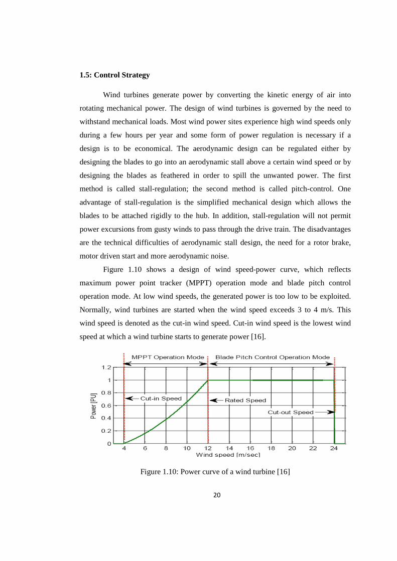
Figure 1.10 shows a design of wind speed-power curve, which reflects
maximum power point tracker (MPPT) operation mode and blade pitch control
operation mode. At low wind speeds, the generated power is too low to be exploited.
Normally, wind turbines are started when the wind speed exceeds 3 to 4 m/s. This
wind speed is denoted as the cut-in wind speed. Cut-in wind speed is the lowest wind
speed at which a wind turbine starts to generate power [16].
Figure 1.10: Power curve of a wind turbine [16]
21
As can be seen in figure 1.10, a wind turbine is started at cut-in wind speed and
the power increases with the cube of the wind speed until the rated wind speed is
reached. Rated wind speed is the wind speed at which the wind turbine generates the
rated power, which is usually the maximum power wind turbine can produce. At wind
speeds from 12 m/s to 25 m/s the power is limited to the rated power of the wind
turbine by means of stall-regulation or pitch-control. At wind speeds over 20 to 25 m/s
wind turbines are normally stopped to avoid high mechanical loads. Cut-out wind
speed is the wind speed at which the turbine ceases power generation and is shut down
to protect the turbine from mechanical damage [16].
1.6: Technical challenges
Most of the wind turbines are located in remote locations due to high wind
speeds and away from the load centers where the grid is weak. These weak grids
experience various disturbances like frequent faults, unbalance voltages and voltage
variations. Till now the penetration level of the wind energy was low and thus
disconnecting of the turbine during these disturbance conditions didn’t impact power
system operation. As more and more electricity is being generated from wind,
disconnection of the turbine during disturbances will impact the power system
operation and even the post disturbance condition leading to under-utilization of wind
turbine. The real challenges associated with the operation of the wind farm are their
performance during disturbances like fault condition, unbalance voltages and
variations in the grid voltage. The location and intermittent nature of wind turbine
machines can cause power quality problems. Wind turbines, especially inductive
machines, tend to absorb reactive power from the system and produce a low power
factor. If wind turbines absorb too much reactive power, the system can become
unstable [17].
The challenges associated with the operation of a wind farm lead to a greater
concern for the operation under disturbances within the nearby power system.
Asymmetric and symmetric faults can lead to voltage instabilities. However, tripping
of the generators due to under voltage and over speed of the generators can result in
22
voltage stability problems and even small disturbances may 1ead to widespread
tripping and associated instabilities [18].
As the penetration of wind increases, the way in which it interacts with the
power system becomes increasingly important. However, for high penetrations,
requirements are likely unreasonable and in some cases may even be detrimental to the
stability of the system. For instance, without voltage regulator controls, the voltage
may often fluctuate outside the acceptable operating range and fast tripping of wind
generators following under voltages have been shown to lead to voltage collapse,
suggesting the need for a low - voltage ride through capability. The problem of voltage
regulation and reactive power control is even greater in the case of a weak connection.
The largest source impedance results in significant fluctuations in the voltage at the
point of common coupling due to changes in power flows and in this case reactive
compensation has been shown to be crucial. The ability to smooth the power
oscillations will result in a more stable terminal voltage; however, reactive
compensation would still be a strict requirement, in steady-state but even more
important during transients [19].
Existing grid connection codes require fault ride-through (FRT) capabilities for
wind turbines. Three-phase short-circuit faults are considered as the most challenging
cases among all. In most of the existing WECSs, the ability to ride through the grid
faults is not possible without control or hardware modifications. The fault ride-through
requirement, also named low-voltage ride-through (LVRT) requirement, imposes great
challenges to wind turbine / converter manufacturers and designers [20].
Along with these issues, integration of wind turbine to grid faces few more
challenges. They are:
1) The fluctuating nature of wind causes power variation and thus the voltage
oscillations.
2) Induction generators are preferred for wind power application, but draw large
amount of reactive power for the excitation purpose from the grid and make the grid
weak.
3) Maintaining voltage at the connection point due to the weak grids, reactive power
absorbed by the induction generators and varying wind power.
23
4) The voltage of a synchronous generator is variable due to variable wind.
Fluctuating voltage and power is a major concern in converter based grid connected
system. This only increases the problem inherent to the power network and also makes
the contribution difficult to manage and regulate the voltage and frequency.
5) Power quality issues like voltage sag, voltage swell, interruption, under voltage,
over voltage, harmonics, voltage unbalance, flicker.
6) Low voltage ride through capability (LVRT).
7) Effect of short circuit ratio on operation of WEC and power quality of grid due to
interconnection of wind farms.
8) Effect of wind turbulence.
9) Harmonic distortion due to integration of synchronous generators.
10) Stability of wind turbine during grid disturbances.
1.7: Aim of the thesis
Wind energy in India has an extremely bright future and there is no doubt that,
in the renewable energy sector, wind power would play a predominant role in adding
clean energy to the country’s grids. India has a huge potential of wind generation and
every year many wind farms are being added and interfaced to the grid. As compared
to developed countries Indian grid is very weak with poor infrastructure. The
percentage of wind-based generation will increase at a faster rate, which will result
into power quality, stability and reactive power management. So there is a need to
study the effect of these factors to identify the main issues which are responsible for
deterioration of power quality, reliability, security and stability of the large wind farm
grid as well as satisfactory operation of generator including ride through capability
during normal as well as fault conditions.
Objectives of the research work of this thesis are:
[1] Study and examine the main issues, which affect power quality, reliability, security
and stability of large scale wind farm when it is connected to grid comprising of
synchronous and induction generator by conducting actual measurements to identify
reactive power, power quality problems, grid stability and security issues including the
24
ride through capability of both types of generator during normal grid and faulted grid
conditions.
[2] Study of effect of RMS voltage variation of grid on the performance of both types
of generators.
[3] Study of the impact of wind generator (both types) on grid supply quality,
reliability and security covering the effect of grid strength and type of connected load
such as linear and nonlinear.
[4] Study of problems associated with wind farm comprising both types of generator
of grid such as stability, reliability, quality and stability of wind turbines.
[5] Provide cost effective solutions for reactive power management, power quality
issues, grid security and reliability issues, including ride through enhancement of wind
generator during normal and faulted conditions with modeling and simulation by
PSCAD software.
1.8: Organization of thesis
This thesis is organized into eight chapters.
Chapter 1 covers the introduction and classification of the wind turbine
concepts & generator types. In this chapter various wind turbine concepts and different
wind generators have been discussed. Three types of typical generator systems used in
large scale wind farms are discussed. Different types of wind power control
mechanisms are presented. Input wind power control ability divides wind energy
conversion system (WECS) into four categories: pitch-controlled, stall-controlled, yaw
control & power electronic controller. Power control ability refers to the aerodynamic
performance of wind turbines. There are different ways to control aerodynamic forces
on the turbine rotor and thus to limit the power in very high winds in order to avoid
the damage to the wind turbine. Control Strategy & technical challenges associated
with wind farms, organization of thesis, contributions are covered.
25
Chapter 2 provides a literature review for modeling and control of the
induction and synchronous generator-based WECS connected to the power grid,
steady state reactive power capability of the generator, power quality issues, low
voltage ride through capability and grid code requirements for connecting wind
turbines to power grid. Moreover, chapter 2 also presents the literature review for the
necessity of an additional reactive power source in the generator-based wind turbine
system. Modeling and control of the STATCOM are used to control the operation of
induction and synchronous generator - based wind turbine system.
Chapter 3 provides problem identification and scope of work. Many
researchers have focused on the study of power quality, reactive power, stability,
flicker, operation of wind energy generator under different grid conditions considering
single type of generators. In large scale wind farms different types of generators are
used with different wind farm topologies. More research was required to study all the
issues mentioned and technical challenges of integration of large scale wind farms
with different types of wind energy generator technologies with different topologies to
provide cost effective optimal solutions.
Detailed scope of work covers study of power quality problems such as short
duration RMS voltage variation (voltage sag, swell and interruption), long duration
RMS voltage variation (under voltage & over voltage), voltage unbalance, flicker,
harmonic distortion along with reactive power issues, low voltage ride through
capability, fault ride through capability, effect of short circuit ratio, wind turbulence
issues, voltage, power & rotor instability during fault related to the integration of large
scale wind farm with different generator technologies, different wind farm topologies
are covered. The impact of factors responsible for deterioration of power quality of the
grid due to operation of different wind turbine generator technologies and the impact
of poor power quality of grid on wind turbine operational behavior, stability during all
conditions of grid, wind farm topologies is covered in the scope of work. Providing
optimal cost effective solution to resolve technical issues related to the integration of
large scale wind farms with different types of wind generators, topologies under
different conditions of the grid are covered.
26
Chapter 4 describes the following four grid connected wind driven generator
system description.
1) Grid connected wind driven squirrel cage (singly fed) induction generator system:
A wind farm typically consists of a large number of individual wind turbine
generators (WTGs) with squirrel cage induction generators (SCIGs) connected by an
internal electrical network. To study the impact of wind farms on the dynamics of the
power system, an important issue is to develop appropriate wind farm models to
represent the dynamics of many individual WTGs. The model is developed and
compared with simulation & validation study in the PSCAD/EMTDC environment
under different wind velocity and fluctuation conditions. Wind generators are
primarily classified as fixed speed or variable speed. For the studies carried out in this
chapter, it focuses on modeling the fixed speed unit. It consists of a 75 MW wind farm
comprising 60 wind turbines, grouped into five clusters of similar properties. Each
grouping contains 12 wind turbines of 1.25 MW unitary rating. The electric generators
studied are squirrel cage machines of 1.6 MVA. The wind turbine designated has a
stall regulated three-bladed horizontal axis rotor coupled to a squirrel cage induction
generator. Each of these wind turbine units consists of rotor, gearbox, squirrel cage
induction generator and a 0.69/33 kV transformer. The large scale wind farm is
connected to 33/132 kV substation to 220 kV, 200 MVA electric grid system (through
220/132 kV grid transformer) and is modeled by using PSCAD simulation software.
2) Grid connected wind driven doubly fed induction generator system:
The DFIG is wound rotor induction generator with the stator windings directly
connected to the constant-frequency three-phase grid and the rotor windings is fed by
the rotor side converter (RSC) and the grid side converter (GSC) connected back-to-
back. At steady state the RSC independently regulates stator active and reactive
powers, whereas GSC keeps the DC link voltage constant independent of magnitude
and direction of the rotor power. In this case the wind farm is represented using the
PSCAD library in PSCAD simulation software where one wind turbine and DFIG are
represented as one equivalent DFIG driven by the single equivalent wind turbine. The
wind turbine having capacity 0.8 MW designated has a stall regulated three-bladed
27
horizontal axis rotor coupled to a wound rotor induction generator having capacity 1
MVA. The large scale wind farm is modeled by using PSCAD simulation.
3) Grid connected wind driven synchronous generator system:
A wind farm typically consists of a large number of individual wind turbine
generators (WTGs) with electrically excited synchronous generators (EESGs)
connected by an internal electrical network. To study the impact of wind farms on the
dynamics of the power system, an important issue is to develop appropriate wind farm
models to represent the dynamics of many individual WTGs. The model is developed
and compared with simulation studies in the PSCAD/EMTDC environment under
different wind velocity and fluctuation conditions. Modeling of variable speed unit is
carried out. It consists of a 75 MW wind farm comprising 45 wind turbines, grouped
into five clusters of similar properties. Each grouping contains 9 wind turbines of 1.67
MW unitary rating. The electric generators are synchronous machines of 2 MVA. The
wind turbine designated has a stall regulated three-bladed horizontal axis rotor coupled
to a synchronous generator. The connection to the grid is then performed through a
full AC/DC/AC converter. The main advantage of this strategy is to allow removing
the gear box in the wind turbine. Each of these wind turbine units consists of rotor,
synchronous generator and a 0.69/33 kV transformer. The large scale wind farm is
modeled by using PSCAD simulation.
4) Large scale wind farm with a combination of singly, doubly fed induction &
synchronous generator system:
A wind farm typically consists of a large number of individual WTGs with
SCIGs, DFIGs & EESGs connected by an internal electrical network. To study the
impact of wind farms on the dynamics of the power system, an important issue is to
develop appropriate wind farm models to represent the dynamics of many individual
WTGs. The model is developed and compared with simulation studies in the
PSCAD/EMTDC environment under different wind velocities and fluctuation
conditions. Modeling of the fixed speed unit & variable speed is carried out. The large
scale wind farm having capacity of 150.8 MW consists of a combination of all SCIGs,
DFIGs & EESGs.
28
In a 75 MW SCIG wind consists of 60 wind turbines, grouped into five
clusters of similar properties. Each grouping contains 12 wind turbines of 1.25 MW
unitary rating. The electric generators are squirrel cage machines of 1.6 MVA. The
wind turbine designated has a stall regulated three-bladed horizontal axis rotor coupled
to a squirrel cage induction generator. In a DFIG wind farm consists of 0.8 MW wind
turbine machine designated has a stall regulated three-bladed horizontal axis rotor
coupled to a wound rotor induction generator having capacity 1 MVA.
In a 75 MW EESG wind farm comprising 45 wind turbines, grouped into five
clusters of similar properties. Each grouping contains 9 wind turbines of 1.67 MW
unitary rating. The electric generators are synchronous machines of 2 MVA. The wind
turbine designated has a stall regulated three-bladed horizontal axis rotor coupled to a
synchronous generator. The large scale wind farm is connected to 33/132 kV
substation to 220 kV, 200 MVA electric grid system and is modeled by using PSCAD
simulation software.
Chapter 5 describes the comparison of SVC, STATCOM and UPFC is
presented and based on technical merits, capabilities of various mentioned devices and
requirements to resolve issues related to the integration of large scale wind farms
interface with the grid, STATCOM device was considered for providing mitigation.
Capacitor sizing criterion to provide reactive power by using STATCOM is discussed.
Rating calculation and location of STATCOM for active, reactive, apparent power,
DC link voltage, Vcmax, DC link capacitance rating is presented.
Chapter 6 provides the effect & mitigation techniques for following generator
system:
1) Grid connected wind driven squirrel cage (singly fed) induction generator system:
In this chapter a wind turbine fed SCIG is modeled using PSCAD and different
power quality issues like short duration variations (voltage sag, swell and
interruption), long duration variation (under voltage, over voltage) harmonics for
linear load & nonlinear load, voltage unbalance, flicker, reactive power issues, LVRT,
effect of the short circuit ratio, effect of wind turbulence & effect of voltage, power &
29
rotor instability are analyzed. In this case study, wind farm with SCIG having capacity
75 MW is connected to 33/132 kV substation to 220 kV, 200 MVA electric grid
system & STATCOM connected at PCC and is modeled using PSCAD/EMTDC
software.
The STATCOM used as a device to mitigate these problems and simulation
results prove that STATCOM is an effective to mitigate these problems during
continuous operation of grid connected wind turbines. Large scale wind farm
consisting of SCIG connected by STATCOM is described in this chapter.
2) Grid connected wind driven doubly fed induction generator system:
Wind turbine fed DFIG is modeled using PSCAD and different power quality
issues like short duration variations (voltage sag, swell and interruption), long duration
variation (under voltage, over voltage) harmonics for linear load & nonlinear load,
voltage unbalance, flicker, reactive power issues, LVRT, the effect of the short circuit
ratio, the effect of turbulence & effect of voltage, power & rotor instability are
analyzed. The STATCOM used as a device to mitigate these problems and simulation
results prove that STATCOM is an effective to mitigate these problems during
continuous operation of grid connected wind turbines. Analysis of large scale wind
farm consisting of double fed induction generator with STATCOM is presented. In
this case study, wind farm with DFIG having capacity 0.8 MW is connected to 33/132
KV substation to 220 kV, 200 MVA electric grid system & STATCOM connected at
PCC and is modeled using PSCAD/EMTDC software. In this case the wind farm is
represented using the PSCAD library in PSCAD simulation software where one wind
turbine and DFIG are represented as one equivalent DFIG driven by the single
equivalent wind turbine. The wind turbine having capacity 0.8 MW designated has a
stall regulated three-bladed horizontal axis rotor coupled to a wound rotor induction
generator having capacity 1 MVA. Wind turbine units consist of rotor, gearbox,
wound rotor induction generator and a 0.69/33 kV transformer. The large scale wind
farm is connected to 33/132 kV substation to 220 kV, 200 MVA electric grid system
& STATCOM connected at PCC and is modeled by using PSCAD simulation
software.
30
3) Grid connected wind driven synchronous generator system:
In this chapter a wind turbine fed EESG is modeled using PSCAD and
different power quality issues like short duration variations (voltage sag, swell and
interruption), long duration variation (under voltage, over voltage) harmonics for
linear load & nonlinear load, voltage unbalance, flicker, reactive power issues, LVRT,
the effect of the short circuit ratio, the effect of turbulence & effect of voltage, power
& rotor instability are analyzed. In this case study, wind farm with EESG having
capacity 75 MW is connected to 33/132 kV substation to 220 kV, 200 MVA electric
grid system & STATCOM connected at PCC and is modeled using PSCAD/EMTDC
software.
The STATCOM used as a device to mitigate these problems and simulation
results prove that STATCOM is an effective means to mitigate these problems during
continuous operation of grid connected wind turbines. Large scale wind farm
consisting of EESG connected by STATCOM is described in this chapter.
4) Large scale wind farm with a combination of squirrel cage, doubly fed induction
& synchronous generator system:
In this chapter large scale wind farm having capacity of 150.8 MW consists of
a combination of all generators SCIG, DFIG and EESG. In a 75 MW SCIG wind farm
consists of 60 wind turbines, grouped into five clusters of similar properties. Each
grouping contains 12 wind turbines of 1.25 MW unitary rating. The electric generators
are squirrel cage machines of 1.6 MVA. The wind turbine designated has a stall
regulated three-bladed horizontal axis rotor coupled to a squirrel cage induction
generator. In a wound rotor induction generator, wind farm consists of 0.8 MW wind
turbine machine designated has a stall regulated three-bladed horizontal axis rotor
coupled to a wound rotor induction generator having capacity 1 MVA. In a 75 MW
EESG wind farm comprising 45 wind turbines, grouped into five clusters of similar
properties. Each grouping contains 9 wind turbines of 1.67 MW unitary rating. The
electric generators are synchronous machines of 2 MVA. The wind turbine designated
has a stall regulated three-bladed horizontal axis rotor coupled to a synchronous
generator. In this case study, a large scale wind farm having capacity 150.8 MW is
connected to 33/132 kV substation to 220 kV, 200 MVA electric grid system &
31
STATCOM connected at PCC and is modeled using PSCAD/EMTDC. Also power
quality issues like short duration variations (voltage sag, swell and interruption), long
duration variation (under voltage, over voltage) harmonics for linear load & nonlinear
load, voltage unbalance, flicker, reactive power issues, LVRT, the effect of the short
circuit ratio, the effect of turbulence & effect of voltage, power & rotor instability are
analyzed. The STATCOM is used to mitigate these issues and simulation results prove
that STATCOM is an effective means to mitigate these problems.
Chapter 6 also gives the cost analysis of all generating systems. A simulation
model of large scale wind farm consisting of squirrel cage, double fed induction
generator & synchronous generator system is designed in PSCAD software without
STACOM connected to the system having wind speed varying from 3 m/s to 30 m/s.
Average power factor is calculated of the system by considering active power &
apparent power. As an induction generator requires reactive power for excitation
purpose. Hence it lowers the power factor of the system. Status of power factor level
& penalty (Monthly) without STATCOM connected to the system are evaluated.
Chapter 7 covers results, discussion and conclusion on the basis of simulation
results of all cases considered in scope of work of this thesis. Simulation studies were
carried out on following configuration of wind farms.
1) Singly fed induction generator wind farm having capacity of 75 MW
comprising of a sixty number of wind turbines.
2) Doubly fed induction generator with 0.8 MW.
3) Synchronous generator having capacity of 75 MW comprising of forty five
numbers of wind turbines.
4) Combining all three mentioned generator aggregated wind farm models
with 150.8 MW capacity.
Different studies carried out to study the impact of grid side power quality
disturbances on the operational behavior of three types of wind energy
generators.
a) Reactive power requirement, variations during different operating conditions
of wind turbines and wind patterns, grid operating conditions under steady
state and transient conditions.
32
b) Evaluation of low voltage fault ride through capability of three types of wind
energy generators connected in different configuration for symmetrical and
unsymmetrical power system faults.
c) Effect of short circuit ratio on operational behavior of different wind
generators. Different parameters of generator studied are active, reactive
power, voltage profile and generator speed.
d) Effect of various power system faults on voltage profile, active power, reactive
power, rotor instability of three types of wind generators operating individually
and in aggregated model.
e) Evaluation of low voltage fault ride through capability of different types of
generators for seven types of voltage sags with different magnitude and
duration, instantaneous, momentary and temporary voltage swell, under and
over voltages with different magnitude and duration, Voltage unbalance.
Different studies are carried out to study the impact of operation of wind
turbine under different operating conditions on grid power quality as follows:
a) Effect of wind turbulence on wind speed with and without pitch angle control
and its impact on power fluctuations.
b) Requirement of reactive power under different operating conditions of three
types of generators.
c) Voltage and current harmonic distortion issues related with operation of three
types of generators with linear and non-linear load.
d) Cost benefits analysis of reactive power compensation.
e) Effect of the short circuit ratio on voltage harmonic distortion during operation
of three types of wind energy generators used in the aggregate model for linear
and for different percentages of nonlinear as a part of the total load.
f) Evaluation of current harmonic emissions at PCC with different short circuit
ratios for aggregate wind model comprising of three types of wind energy
generators.
Chapter 8 describes the future scope work, bibliography & appendix

33
1.9: Contributions
The main contribution of this thesis is as follows:
1) Study of all the issues related to the integration of large scale wind farms to grid
with different generators, wind farm topologies and all related factors which may
govern power quality issues. Simulation of a large scale wind farm model includes a
wind turbine with different types of generators, which are SFIG, DFIG & EESG
mainly used in large scale wind farms. All generators are connected in parallel at the
point of common coupling (PCC) and connected to the utility grid through substation.
Detailed simulation studies were carried out with following cases:
a) SCIG wind farm having capacity of 75 MW.
b) DFIG wind farm having capacity 0.8 MW.
c) EESG wind farm having capacity of 75 MW.
d) Combining all three mentioned generator aggregated wind farm models
with 150.8 MW capacity.
2) Evaluation of low voltage fault ride through capability of different types of
generators for seven types of voltage sags A, B, C, D, E, F and G with different
magnitude and duration, instantaneous, momentary and temporary voltage swell,
under voltage and over voltages with different magnitude and duration.
3) Effect of operation of singly fed, doubly fed induction and synchronous generators
on current harmonic distortion at PCC with different short circuit ratios with linear and
non-linear load connected to the grid and comparison of current harmonic limits at
PCC as per IEEE 519-1992 Standard.
4) Effect of grid side % voltage unbalance on the operation of singly, doubly fed
induction and synchronous generators.
5) Study of reactive power requirement in case of wind farm with singly fed induction
generators, doubly fed induction generators, synchronous generators and wind farm
with all three types of generators.
34
6) Effect of symmetrical and unsymmetrical grid faults on a low voltage ride through
capability of three different types of wind generators connected in different
configurations.
7) Effect of short circuit ratio on operational behavior of different generators.
Different parameters of generator studied are active power, reactive power, voltage
profile and generator speed.
8) Effect of wind turbulence on wind speed with and without pitch angle control and
its effect on power fluctuations.
9) Effect of symmetrical and unsymmetrical grid faults on voltage profile, active,
reactive power, rotor instability on three types of wind generators connected to wind
farm in different configurations.
10) Effect of operation of three types of wind generators on voltage flicker.
Based on the analysis of these studies, various issues related to interconnection
of large scale wind turbines were identified and cost effective solution is provided for
mitigation of power quality problems, reactive power, harmonic distortion, low
voltage ride through capability by use of static synchronous compensator
(STATCOM). Simulation results were obtained with and without STATCOM.
The outcome of research work will be useful to Indian utilities, policy makers,
regulators, wind energy farm developers, R & D bodies and various researchers.