Embed Size (px)
Citation preview

CHAPTER 1
GENERAL
TDOT ROADWAY DESIGN GUIDELINES
CHAPTER 1 GENERAL
English Revised: 03/02/20
1-i
CHAPTER 1 GENERAL
Table of Contents
INTRODUCTION ........................................................................................................................ v
SECTION 1 – PROJECT INFORMATION .................................................................................. 1
1-100.00 PROJECT RECORDS ............................................................................................. 1
1-101.00 PROJECT SCOPE AND CHANGES IN SCOPE ..................................................... 1
1-102.00 PROJECT FOLDER ................................................................................................ 1
1-103.00 CHARGING TIME TO PROJECTS .......................................................................... 1
1-104.00 PDF PLAN SHEET SIZE ......................................................................................... 1
1-105.00 FILENET PROJECT DELIVERABLES ..................................................................... 1
1-105.01 PRELIMINARY FIELD REVIEW FILENET SUBMITTAL PACKAGE .................. 2
1-105.02 PRELIMINARY FILENET SUBMITTAL PACKAGE ............................................ 3
1-105.03 SITE REVIEW FILENET SUBMITTAL PACKAGE ............................................. 4
1-105.04 R.O.W. FIELD REVIEW FILENET SUBMITTAL PACKAGE .............................. 5
1-105.05 R.O.W. FILENET SUBMITTAL PACKAGE ........................................................ 7
1-105.06 R.O.W. REVISION FILENET SUBMITTAL PACKAGE ...................................... 9
1-105.07 CONSTRUCTION FIELD REVIEW FILENET SUBMITTAL PACKAGE ............12
1-105.08 FINAL CONSTRUCTION PLANS REVIEW FILENET SUBMITTAL PACKAGE 14
1-105.09 CONSTRUCTION FILENET SUBMITTAL PACKAGE ......................................17
1-105.10 LETTING REVISION FILENET SUBMITTAL PACKAGE ..................................18
1-105.11 CONSTRUCTION REVISION FILENET SUBMITTAL PACKAGE ....................19
1-106.00 FILENET PROPERTIES.........................................................................................21
1-106.01 LATITUDE AND LONGITUDE ..........................................................................21
1-106.02 PROJECT CONTRACT NUMBER ....................................................................22
1-107.00 REMOVAL OF PLANS FROM FILENET ................................................................22
SECTION 2 – PLANS PRODUCTION .......................................................................................24
1-200.00 QUALITY ASSURANCE-QUALITY CONTROL ......................................................24
1-201.00 ROADWAY DESIGN CHECKLISTS .......................................................................24
1-202.00 PREPARATION OF PLAN SHEETS ......................................................................25
TDOT ROADWAY DESIGN GUIDELINES
CHAPTER 1 GENERAL
English Revised:03/02/20
1-ii
1-202.01 SHEET BORDERS ...........................................................................................26
1-202.02 SHEET SCALES ..............................................................................................27
1-202.03 SHEET TITLE BLOCK ......................................................................................27
1-202.04 ENGINEER’S SEAL BLOCK ON SHEETS .......................................................28
1-202.05 COORDINATE NOTATIONS ON SHEETS .......................................................28
1-202.06 PLAN PHASE STAMPS ...................................................................................29
1-203.00 DEVELOPMENT OF TITLE SHEETS .....................................................................31
1-204.00 PRELIMINARY TITLE SHEETS .............................................................................31
1-204.01 PROJECT DESCRIPTION ...............................................................................33
1-204.02 SPECIAL NOTES .............................................................................................34
1-204.03 PROJECT, DESIGNER, AND MANAGER IDENTIFICATION ...........................35
1-204.04 MAP, MAP SCALE, AND NORTH ARROW ......................................................36
1-204.05 PROJECT LIMITS ............................................................................................36
1-204.06 PROJECT LENGTHS .......................................................................................37
1-204.07 PROJECT LOCATION AND BRIDGE ID NUMBER ..........................................38
1-204.08 CHIEF ENGINEER AND COMMISSIONER SIGNATURES AND ENGINEER’S
SEAL BLOCK ...................................................................................................39
1-204.09 PRELIMINARY INDEX OF SHEETS ................................................................39
1-204.10 EXCLUSIONS OR NO EXCLUSIONS ..............................................................40
1-204.11 TRAFFIC DATA AND SURVEY DATA BLOCK ................................................41
1-204.12 PLAN PHASE STAMPS ...................................................................................42
1-204.13 ROAD CLOSED DURING CONSTRUCTION ...................................................43
1-204.14 DESIGN EXCEPTION APPROVAL DATES .....................................................43
1-204.15 CHAPTER 86 ELIGIBILITY FOR UTILITIES .....................................................43
1-205.00 RIGHT-OF-WAY TITLE SHEET ..............................................................................45
1-205.01 R.O.W. INDEX OF SHEETS .............................................................................46
1-205.02 WORK ZONE SIGNIFICANCE DETERMINATION ...........................................48
1-205.03 SEALING THE R.O.W. TITLE SHEET ..............................................................49
1-206.00 CONSTRUCTION TITLE SHEET ...........................................................................50
1-206.01 CONSTRUCTION INDEX OF SHEETS ............................................................51
1-206.02 SEALING CONSTRUCTION PLANS ................................................................53
TDOT ROADWAY DESIGN GUIDELINES
CHAPTER 1 GENERAL
English Revised:03/02/20
1-iii
1-207.00 RESURFACING TITLE SHEET ...............................................................................54
SECTION 3 – SURVEY INFORMATION ...................................................................................56
1-300.00 SURVEY REQUIREMENTS ...................................................................................56
1-301.00 COORDINATE VALUES ........................................................................................56
1-302.00 TVA TRANSMISSION LINES .................................................................................56
1-303.00 DISTANCES, BEARINGS, AND CONTROL POINTS .............................................57
1-304.00 TRACT NUMBERS ON PLANS ..............................................................................57
1-305.00 UPDATING SURVEYS ...........................................................................................57
SECTION 4 – ESTIMATES .......................................................................................................59
1-400.00 ESTIMATED ROADWAY QUANTITIES .................................................................59
1-401.00 CREATING THE PRELIMINARY ROADWAY QUANTITIES ESTIMATE ................60
1-402.00 SUBMITTAL OF ESTIMATES ................................................................................63
1-402.01 SUBMITTAL OF THE PRELIMINARY ESTIMATE ............................................63
1-402.02 SUBMITTAL OF R.O.W. ESTIMATE FOR R.O.W. OR UTILITIES ONLY
FUNDING .........................................................................................................63
1-402.03 RESUBMITTALS OF ESTIMATES DUE TO AN INSTRUCTIONAL BULLETIN
OR ROADWAY DESIGN GUIDELINES CHANGE ............................................65
1-402.04 SUBMITTAL OF CONSTRUCTION ESTIMATE FOR CONSTRUCTION FIELD
REVIEW ...........................................................................................................66
1-402.05 SUBMITTAL OF CONSTRUCTION ESTIMATE FOR LETTING PROCESS .....68
1-402.06 REVISION OF CONSTRUCTION ESTIMATE FOR LETTING PROCESS ........69
1-403.00 FOOTNOTES FOR ROADWAY ESTIMATED QUANTITY SHEET ........................70
1-404.00 ESTIMATE CONFIDENTIALITY .............................................................................71
1-405.00 FINANCIAL PLANS ................................................................................................71
SECTION 5 – FIELD REVIEWS ................................................................................................73
1-500.00 TYPES OF FIELD REVIEWS .................................................................................73
1-501.00 FIELD REVIEW PROCEDURES ............................................................................77
1-502.00 SCHEDULING ........................................................................................................77
1-502.01 INTERNAL DISTRIBUTION ..............................................................................77
1-502.02 EXTERNAL DISTRIBUTION TO AGENCIES OR MUNICIPALITIES ................84
1-503.00 FIELD REVIEW REPORT ......................................................................................85
SECTION 6 –PUBLIC HEARINGS/MEETINGS ........................................................................87
TDOT ROADWAY DESIGN GUIDELINES
CHAPTER 1 GENERAL
English Revised:03/02/20
1-iv
1-600.00 PUBLIC HEARING AND PUBLIC MEETING REQUIREMENTS ...........................87
SECTION 7 – VALUE ENGINEERING ......................................................................................92
1-700.00 VALUE ENGINEERING..........................................................................................92
1-701.00 VALUE ENGINEERING OFFICE RESPONSIBILITIES ..........................................92
1-702.00 VALUE ENGINEERING PROJECT SELECTION POLICY .....................................92
1-703.00 VALUE ENGINEERING ANALYSIS PROCEDURES .............................................93
1-703.01 IDENTIFYING AND SCHEDULING VALUE ENGINEERING ANALYSIS ..........93
1-703.02 ASSEMBLING THE VALUE ENGINEERING ANALYSIS TEAM .......................94
1-703.03 VALUE ENGINEERING JOB PLAN ..................................................................94
1-703.04 PRESENTATION OF RECOMMENDATIONS ..................................................95
1-704.00 VALUE ENGINEERING WORKBOOKS .................................................................95
1-705.00 IMPLEMENTATIONS OF APPROVED RECOMMENDATIONS .............................95
TDOT ROADWAY DESIGN GUIDELINES
CHAPTER 1 GENERAL
English Revised:03/02/20
1-v
INTRODUCTION
ROADWAY DESIGN GUIDELINES AND STANDARD DRAWINGS
Roadway Design Guidelines and Standard Drawings have been created to ensure that there is consistency in TDOT projects across the state. The Roadway Design Guidelines and Standard Drawings indicate the current recognized design standards for new construction or reconstruction of existing highways and shall be utilized while giving due regard to topography, natural conditions, availability of road material, and prevailing traffic conditions.
Throughout these guidelines you will see the following terms used. To clarify the meanings
intended in this guide by the use of these words, the following definitions apply:
• Designer – HQ Design, Project Development, or Consultant Designer
• Design Manager – HQ Design, Project Development, or Consultant Design Manager
• Design Team – HQ Design, Project Development, or Consultant Design Manager and
Consultant
• Technical Report – Transportation planning reports (i.e. Transportation Investment
Reports (TIR), Transportation Planning Report (TPR)) developed by the Strategic
Transportation Investments Division.

TDOT ROADWAY DESIGN GUIDELINES
CHAPTER 1 GENERAL
English Revised:03/02/20
1-vi
This page is left blank intentionally.
TDOT ROADWAY DESIGN GUIDELINES
CHAPTER 1 GENERAL
SECTION 1 PROJECT INFORMATION
English Revised:03/02/20
1-1
SECTION 1 – PROJECT INFORMATION
1-100.00 PROJECT RECORDS
It is essential for every Designer to create and maintain a detailed history of the design
process for each of their projects. Information in the project records may be used if a problem arises
during or after construction of the project. For example, records may be referenced after a flood
causes property damage or for other legal claims in court. Examples of records to be kept are
described in Section 1-102.00 Project Folder.
1-101.00 PROJECT SCOPE AND CHANGES IN SCOPE
As a project develops, the designer shall contact the Strategic Transportation Investments
Division (STID) ([email protected], [email protected], [email protected],
[email protected]) and Program Development and Scheduling Office ([email protected])
if the scope of the project as defined in the technical report and/or MPO TIP cannot be met. This
includes all horizontal and vertical elements that would result in a design exception request, and/or
other variations from the original scope such as typical section changes, additional right-of-way
needs, project termini, etc. When designers submit estimates (see Section 1-402.00 Submittal of
Estimates and all subsections), the Designer shall request the monetary value of the estimate from
the Bid Analysis and Estimating Office. If the estimate increases by more than 10% from the
original technical report, the Strategic Transportation Investments Division and Program
Development and Administration Division shall be contacted. If a scope change requires a
modification to the PPRM project description, the Environmental Division shall be contacted.
1-102.00 PROJECT FOLDER
Each Designer will be required to maintain an up-to-date digital project folder that contains
information on the project for all three phases of development (Preliminary, Right-of-Way (R.O.W.),
and Construction). The typical roadway design project folder shall consist of information kept in
chronological order by dates and divided into categories. The following are the categories and
examples of the types of information that may be found in each:
1. Deliverable Requests and Reports:
• Traffic data request and report
• Initial Studies request and corresponding letters and reports
• Additional survey requests
• Environmental documents
2. Correspondence:
TDOT ROADWAY DESIGN GUIDELINES
CHAPTER 1 GENERAL
SECTION 1 PROJECT INFORMATION
English Revised:03/02/20
1-2
• Funding letters
• Departmental emails and correspondence including any notes taken from
verbal conversations
• Outside agency emails and correspondence including any notes taken from
verbal conversations
3. Field Reviews\Public Meetings:
• Letters sent for invitations or appointments for field reviews or public
meetings
• Field review reports including sign in sheet for Preliminary, Site, R.O.W.,
Constructability, Construction, and Final Field Review (all reviews that are
applicable to project)
• Documentation related to Public Meetings
4. Calculations:
• Pavement quantities
• Sight distance
• Guardrail - length of need
• Drainage - including any reports exported from approved drainage programs
• Erosion Control
• Grading Quantities (See Section 6-601.00, Submission of Grading Quantities
Sheets)
• Quantities received from other divisions (signals, signs, utilities, etc.)
5. Estimated Quantities Excel file
For each project, a folder shall be made for each of the categories and then placed in an
Adobe PDF Portfolio or zip file. At Construction turn-in, the Designer shall place the Adobe Portfolio
or zip file containing the entire project folder onto FileNet with the naming convention: nnnnnn-nn-
ProjectFolder.pdf or nnnnnn-nn-ProjectFolder.zip. The nnnnnn-nn-ProjectFolder.pdf/ nnnnnn-nn-
ProjectFolder.zip file will become a complete "Design Records" file and a part of the legal
documents substantiating the final Construction Plans. It is the responsibility of the Designer or
Design Manager (for Consultant designed projects) to maintain the project folder until the
construction project is complete.
Upon receipt of the Notice of Completion from the Regional Operations Office, the Designer
or Design Manager shall upload any additional project information pertaining to the project
(revisions, requests, correspondence with Operations and/or HQ Construction Division, etc.) that
has occurred since the initial construction turn-in with the naming convention nnnnnn-nn-
ProjectFolder-Addendum.pdf/nnnnnn-nn-ProjectFolder-Addendum.zip.

TDOT ROADWAY DESIGN GUIDELINES
CHAPTER 1 GENERAL
SECTION 1 PROJECT INFORMATION
English Revised:03/02/20
1-1
1-103.00 CHARGING TIME TO PROJECTS
For all new projects or projects with design currently being charged to the Preliminary
Engineering NEPA (PE-N) number, Designers shall charge design work to the Preliminary
Engineering NEPA (PE-N) number through preliminary plans development. Preliminary plans
development is defined as all design work prior to issuing plans for R.O.W. acquisition or for utilities
only, as covered under the TDOT/FHWA Preliminary Design Agreement. Once plans are submitted
for R.O.W. acquisition or for utilities only, Designers shall begin charging design work to the
Preliminary Engineering Design (PE-D) number.
Designers and Managers are reminded that a task profile ID, which is the TX number for the
timesheet, will need to be set up in Edison for the Preliminary Engineering NEPA (PE-N) number
and PE-D number at the appropriate stage to ensure that time is charged to the correct funding
source. The Design Manager shall request the task profile ID numbers. If there is a child PIN
associated with the project, check with the Program Development Scheduling Office to determine
what number should be used to charge time.
1-104.00 PDF PLAN SHEET SIZE
PDF plans shall be full-size plans. It is essential that the correct plan size be used when
making the PDFs to ensure that printing of the plans will be to scale. Plans Assembly personnel
must combine plan sets from several divisions during the Letting phase. Personnel in this group can
refuse PDFs that are not the correct size. If approved TDOT sheet borders are used as discussed
in Section 1-202.01, Sheet Borders, the PDFs will be the correct size for 34” X 22” which shows as
33” X 21” on the PDF size and 32” X 21” for cross section sheets in Adobe Acrobat.
For further guidance, refer to the document Creating PDFs from DGNs.pdf located on the
Standard Design CADD Files and Documents webpage.
1-105.00 FILENET PROJECT DELIVERABLES
Designers and Design Managers are responsible for archiving project development
records for all new construction, reconstruction, and resurfacing projects on the Design
folder on the FileNet server utilized by the Department. Unless specified otherwise, when this
document refers to FileNet uploads, it is referring to the Design folder. For guidance in creating a
composite plan set in the *.pdf format refer to the document Creating PDFs from DGNs.pdf
located on the Standard Design CADD Files and Documents webpage.
FileNet archiving shall include all projects with the most recently completed deliverable or
plan set, estimate file, approved design exception, and Traffic Management Plan on the FileNet
server. A complete plan set (including cross-sections) in PDF format shall include all roadway
TDOT ROADWAY DESIGN GUIDELINES
CHAPTER 1 GENERAL
SECTION 1 PROJECT INFORMATION
English Revised:03/02/20
1-2
plan sheets normally found in the deliverable. The project design files (*.dgn, *.sht, *.tin, * .x lsm,
and *.gpk) will be archived with a software program having the capability of making a compressed
(*.zip) file. This compressed (*.zip) file shall not be password protected.
For further guidance, refer to the FileNet Project Deliverables document located on the
Roadway Design Guidelines webpage. This document lists the project deliverables and plan sets
that shall be loaded on the FileNet server.
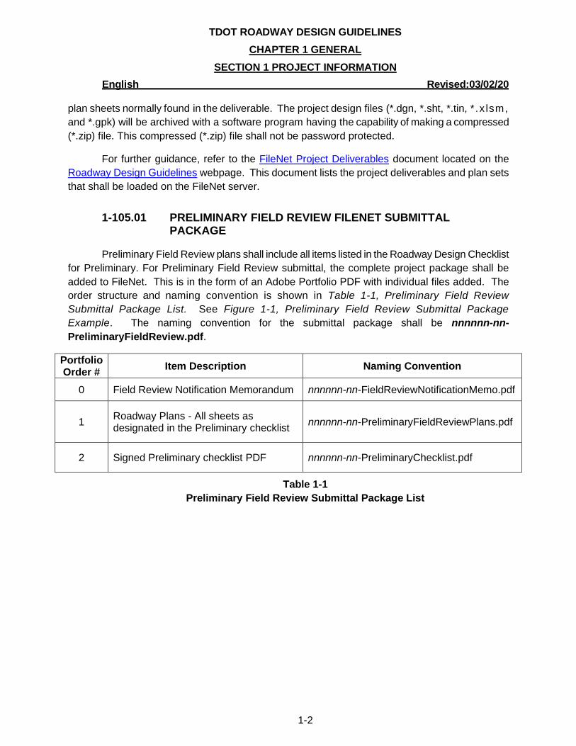
1-105.01 PRELIMINARY FIELD REVIEW FILENET SUBMITTAL PACKAGE
Preliminary Field Review plans shall include all items listed in the Roadway Design Checklist
for Preliminary. For Preliminary Field Review submittal, the complete project package shall be
added to FileNet. This is in the form of an Adobe Portfolio PDF with individual files added. The
order structure and naming convention is shown in Table 1-1, Preliminary Field Review
Submittal Package List. See Figure 1-1, Preliminary Field Review Submittal Package
Example. The naming convention for the submittal package shall be nnnnnn-nn-
PreliminaryFieldReview.pdf.
Portfolio Order #
Item Description Naming Convention
0 Field Review Notification Memorandum nnnnnn-nn-FieldReviewNotificationMemo.pdf
1 Roadway Plans - All sheets as designated in the Preliminary checklist
nnnnnn-nn-PreliminaryFieldReviewPlans.pdf
2 Signed Preliminary checklist PDF nnnnnn-nn-PreliminaryChecklist.pdf
Table 1-1
Preliminary Field Review Submittal Package List
TDOT ROADWAY DESIGN GUIDELINES
CHAPTER 1 GENERAL
SECTION 1 PROJECT INFORMATION
English Revised:03/02/20
1-3
Figure 1-1
Preliminary Submittal Package Example
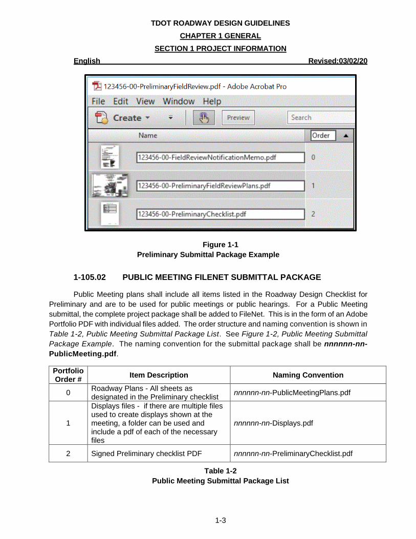
1-105.02 PUBLIC MEETING FILENET SUBMITTAL PACKAGE
Public Meeting plans shall include all items listed in the Roadway Design Checklist for
Preliminary and are to be used for public meetings or public hearings. For a Public Meeting
submittal, the complete project package shall be added to FileNet. This is in the form of an Adobe
Portfolio PDF with individual files added. The order structure and naming convention is shown in
Table 1-2, Public Meeting Submittal Package List. See Figure 1-2, Public Meeting Submittal
Package Example. The naming convention for the submittal package shall be nnnnnn-nn-
PublicMeeting.pdf.
Portfolio Order #
Item Description Naming Convention
0 Roadway Plans - All sheets as designated in the Preliminary checklist
nnnnnn-nn-PublicMeetingPlans.pdf
1
Displays files - if there are multiple files used to create displays shown at the meeting, a folder can be used and include a pdf of each of the necessary files
nnnnnn-nn-Displays.pdf
2 Signed Preliminary checklist PDF nnnnnn-nn-PreliminaryChecklist.pdf
Table 1-2
Public Meeting Submittal Package List
TDOT ROADWAY DESIGN GUIDELINES
CHAPTER 1 GENERAL
SECTION 1 PROJECT INFORMATION
English Revised:03/02/20
1-4
Figure 1-2
Public Meeting Submittal Package Example
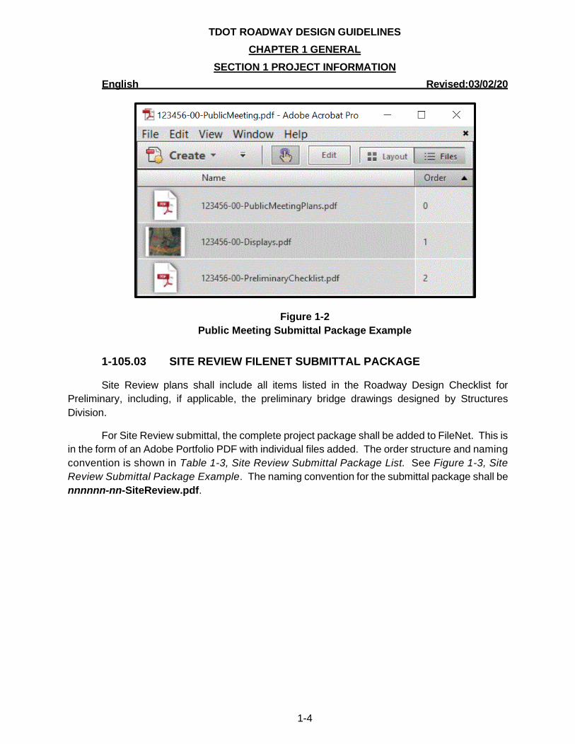
1-105.03 SITE REVIEW FILENET SUBMITTAL PACKAGE
Site Review plans shall include all items listed in the Roadway Design Checklist for
Preliminary, including, if applicable, the preliminary bridge drawings designed by Structures
Division.
For Site Review submittal, the complete project package shall be added to FileNet. This is
in the form of an Adobe Portfolio PDF with individual files added. The order structure and naming
convention is shown in Table 1-3, Site Review Submittal Package List. See Figure 1-3, Site
Review Submittal Package Example. The naming convention for the submittal package shall be
nnnnnn-nn-SiteReview.pdf.
TDOT ROADWAY DESIGN GUIDELINES
CHAPTER 1 GENERAL
SECTION 1 PROJECT INFORMATION
English Revised:03/02/20
1-5
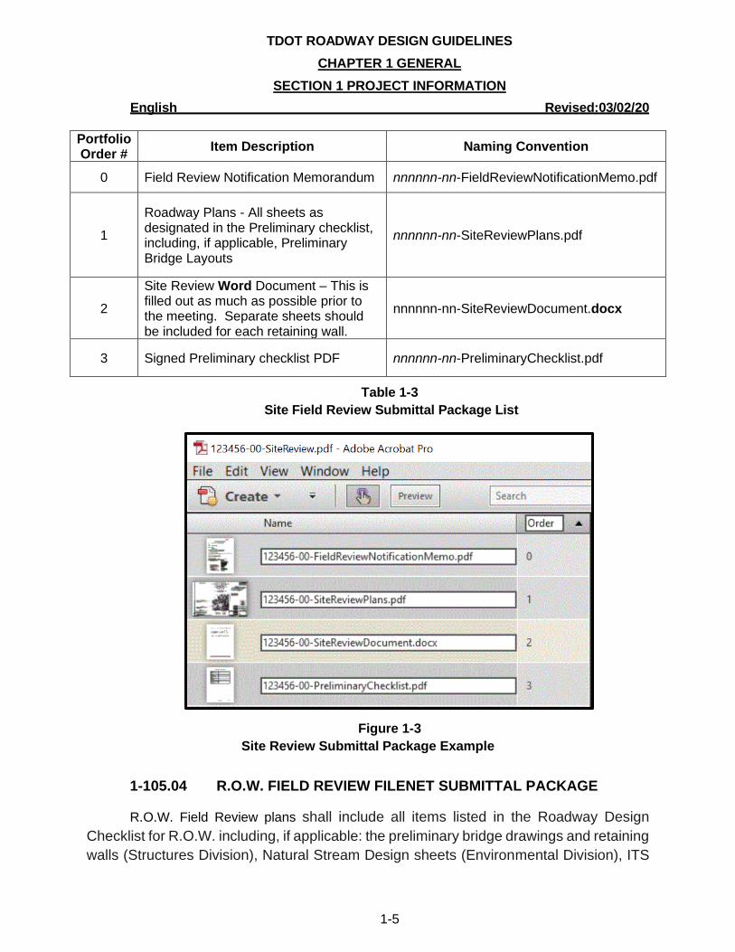
Portfolio Order #
Item Description Naming Convention
0 Field Review Notification Memorandum nnnnnn-nn-FieldReviewNotificationMemo.pdf
1
Roadway Plans - All sheets as designated in the Preliminary checklist, including, if applicable, Preliminary Bridge Layouts
nnnnnn-nn-SiteReviewPlans.pdf
2
Site Review Word Document – This is filled out as much as possible prior to the meeting. Separate sheets should be included for each retaining wall.
nnnnnn-nn-SiteReviewDocument.docx
3 Signed Preliminary checklist PDF nnnnnn-nn-PreliminaryChecklist.pdf
Table 1-3
Site Field Review Submittal Package List
Figure 1-3
Site Review Submittal Package Example
1-105.04 R.O.W. FIELD REVIEW FILENET SUBMITTAL PACKAGE
R.O.W. Field Review plans shall include all items listed in the Roadway Design
Checklist for R.O.W. including, if applicable: the preliminary bridge drawings and retaining
walls (Structures Division), Natural Stream Design sheets (Environmental Division), ITS
TDOT ROADWAY DESIGN GUIDELINES
CHAPTER 1 GENERAL
SECTION 1 PROJECT INFORMATION
English Revised:03/02/20
1-6
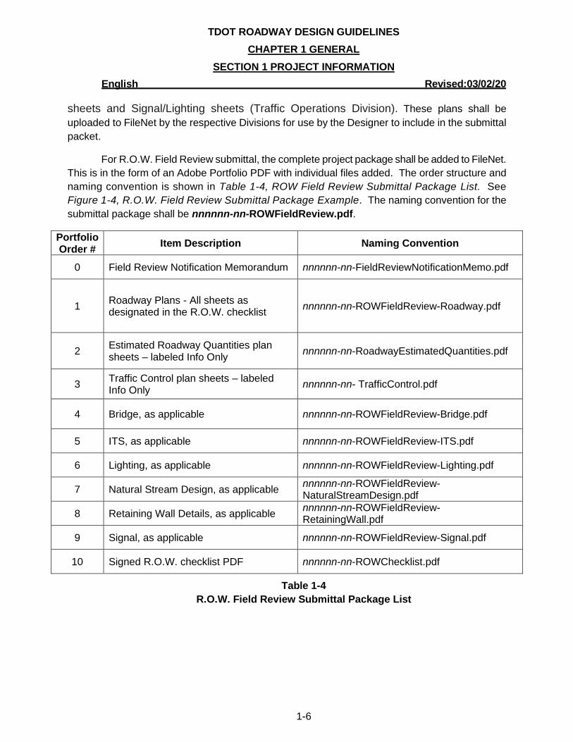
sheets and Signal/Lighting sheets (Traffic Operations Division). These plans shall be
uploaded to FileNet by the respective Divisions for use by the Designer to include in the submittal
packet.
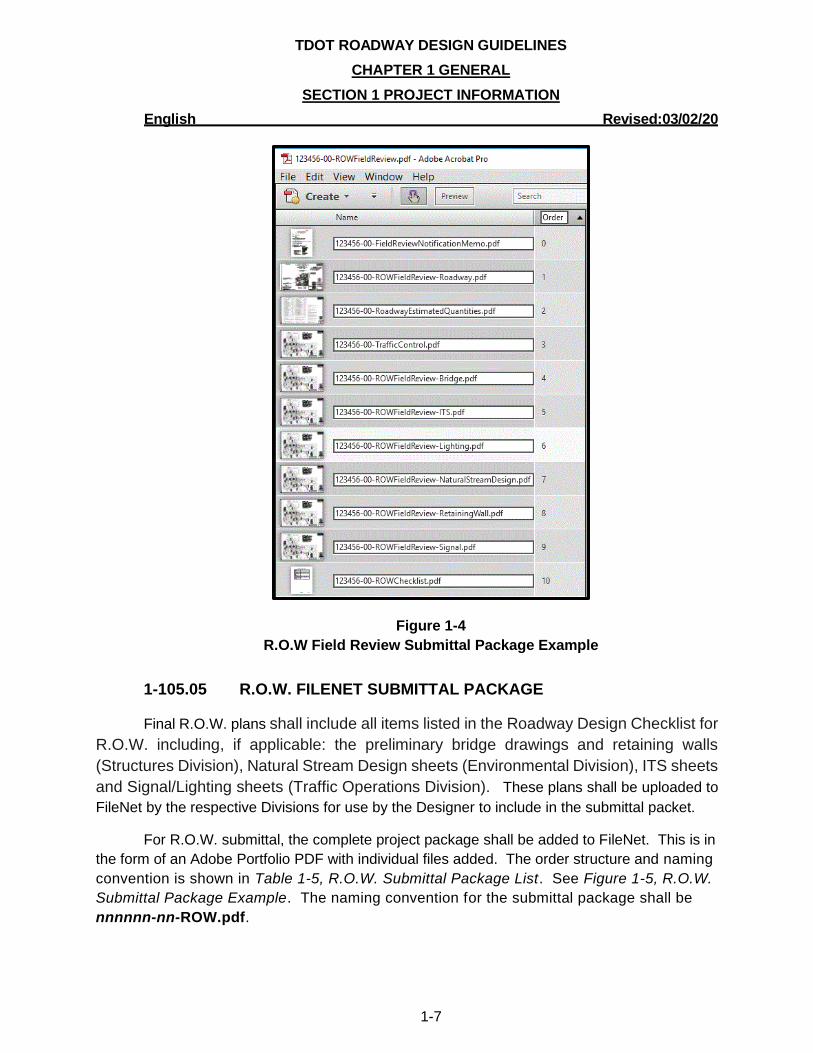
For R.O.W. Field Review submittal, the complete project package shall be added to FileNet.
This is in the form of an Adobe Portfolio PDF with individual files added. The order structure and
naming convention is shown in Table 1-4, ROW Field Review Submittal Package List. See
Figure 1-4, R.O.W. Field Review Submittal Package Example. The naming convention for the
submittal package shall be nnnnnn-nn-ROWFieldReview.pdf.
Portfolio Order #
Item Description Naming Convention
0 Field Review Notification Memorandum nnnnnn-nn-FieldReviewNotificationMemo.pdf
1 Roadway Plans - All sheets as designated in the R.O.W. checklist
nnnnnn-nn-ROWFieldReview-Roadway.pdf
2 Estimated Roadway Quantities plan sheets – labeled Info Only
nnnnnn-nn-RoadwayEstimatedQuantities.pdf
3 Traffic Control plan sheets – labeled Info Only
nnnnnn-nn- TrafficControl.pdf
4 Bridge, as applicable nnnnnn-nn-ROWFieldReview-Bridge.pdf
5 ITS, as applicable nnnnnn-nn-ROWFieldReview-ITS.pdf
6 Lighting, as applicable nnnnnn-nn-ROWFieldReview-Lighting.pdf
7 Natural Stream Design, as applicable nnnnnn-nn-ROWFieldReview-NaturalStreamDesign.pdf
8 Retaining Wall Details, as applicable nnnnnn-nn-ROWFieldReview-RetainingWall.pdf
9 Signal, as applicable nnnnnn-nn-ROWFieldReview-Signal.pdf
10 Signed R.O.W. checklist PDF nnnnnn-nn-ROWChecklist.pdf
Table 1-4
R.O.W. Field Review Submittal Package List
TDOT ROADWAY DESIGN GUIDELINES
CHAPTER 1 GENERAL
SECTION 1 PROJECT INFORMATION
English Revised:03/02/20
1-7
Figure 1-4
R.O.W Field Review Submittal Package Example
1-105.05 R.O.W. FILENET SUBMITTAL PACKAGE
Final R.O.W. plans shall include all items listed in the Roadway Design Checklist for
R.O.W. including, if applicable: the preliminary bridge drawings and retaining walls
(Structures Division), Natural Stream Design sheets (Environmental Division), ITS sheets
and Signal/Lighting sheets (Traffic Operations Division). These plans shall be uploaded to
FileNet by the respective Divisions for use by the Designer to include in the submittal packet.
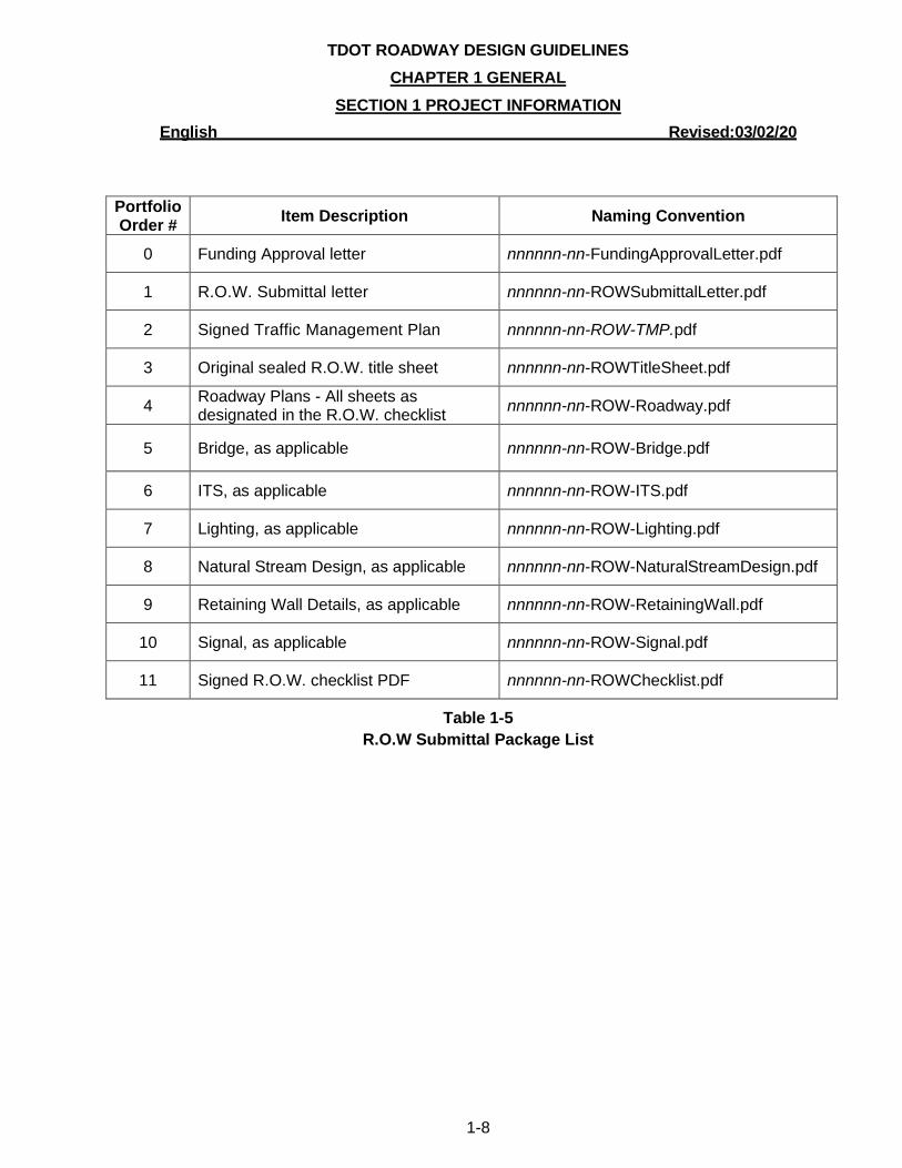
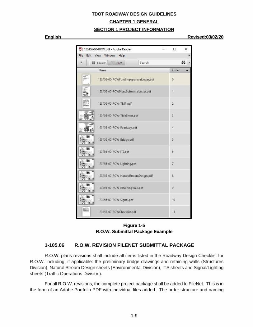
For R.O.W. submittal, the complete project package shall be added to FileNet. This is in
the form of an Adobe Portfolio PDF with individual files added. The order structure and naming
convention is shown in Table 1-5, R.O.W. Submittal Package List. See Figure 1-5, R.O.W.
Submittal Package Example. The naming convention for the submittal package shall be
nnnnnn-nn-ROW.pdf.
TDOT ROADWAY DESIGN GUIDELINES
CHAPTER 1 GENERAL
SECTION 1 PROJECT INFORMATION
English Revised:03/02/20
1-8
Portfolio Order #
Item Description Naming Convention
0 Funding Approval letter nnnnnn-nn-FundingApprovalLetter.pdf
1 R.O.W. Submittal letter nnnnnn-nn-ROWSubmittalLetter.pdf
2 Signed Traffic Management Plan nnnnnn-nn-ROW-TMP.pdf
3 Original sealed R.O.W. title sheet nnnnnn-nn-ROWTitleSheet.pdf
4 Roadway Plans - All sheets as designated in the R.O.W. checklist
nnnnnn-nn-ROW-Roadway.pdf
5 Bridge, as applicable nnnnnn-nn-ROW-Bridge.pdf
6 ITS, as applicable nnnnnn-nn-ROW-ITS.pdf
7 Lighting, as applicable nnnnnn-nn-ROW-Lighting.pdf
8 Natural Stream Design, as applicable nnnnnn-nn-ROW-NaturalStreamDesign.pdf
9 Retaining Wall Details, as applicable nnnnnn-nn-ROW-RetainingWall.pdf
10 Signal, as applicable nnnnnn-nn-ROW-Signal.pdf
11 Signed R.O.W. checklist PDF nnnnnn-nn-ROWChecklist.pdf
Table 1-5
R.O.W Submittal Package List
TDOT ROADWAY DESIGN GUIDELINES
CHAPTER 1 GENERAL
SECTION 1 PROJECT INFORMATION
English Revised:03/02/20
1-9
Figure 1-5
R.O.W. Submittal Package Example
1-105.06 R.O.W. REVISION FILENET SUBMITTAL PACKAGE
R.O.W. plans revisions shall include all items listed in the Roadway Design Checklist for
R.O.W. including, if applicable: the preliminary bridge drawings and retaining walls (Structures
Division), Natural Stream Design sheets (Environmental Division), ITS sheets and Signal/Lighting
sheets (Traffic Operations Division).
For all R.O.W. revisions, the complete project package shall be added to FileNet. This is in
the form of an Adobe Portfolio PDF with individual files added. The order structure and naming
TDOT ROADWAY DESIGN GUIDELINES
CHAPTER 1 GENERAL
SECTION 1 PROJECT INFORMATION
English Revised:03/02/20
1-10
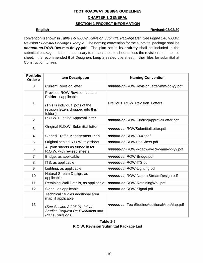
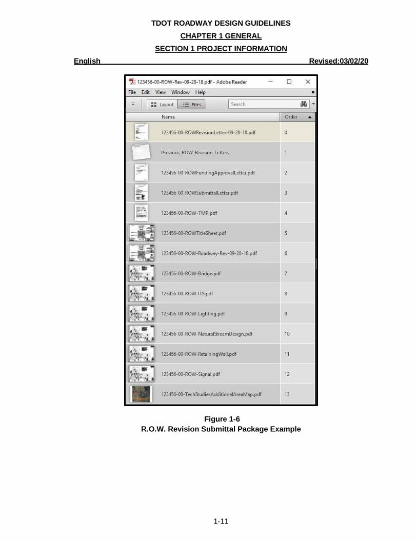
convention is shown in Table 1-6 R.O.W. Revision Submittal Package List. See Figure 1-6, R.O.W.
Revision Submittal Package Example. The naming convention for the submittal package shall be
nnnnnn-nn-ROW-Rev-mm-dd-yy.pdf. The plan set in its entirety shall be included in the
submittal package. It is not necessary to re-seal the title sheet unless the revision is on the title
sheet. It is recommended that Designers keep a sealed title sheet in their files for submittal at
Construction turn-in.
Portfolio Order #
Item Description Naming Convention
0 Current Revision letter nnnnnn-nn-ROWRevisionLetter-mm-dd-yy.pdf
1
Previous ROW Revision Letters Folder, if applicable (This is individual pdfs of the revision letters dropped into this folder.)
Previous_ROW_Revision_Letters
2 R.O.W. Funding Approval letter
nnnnnn-nn-ROWFundingApprovalLetter.pdf
3 Original R.O.W. Submittal letter
nnnnnn-nn-ROWSubmittalLetter.pdf
4 Signed Traffic Management Plan nnnnnn-nn-ROW-TMP.pdf
5 Original sealed R.O.W. title sheet nnnnnn-nn-ROWTitleSheet.pdf
6 All plan sheets as turned in for R.O.W. with revised sheets
nnnnnn-nn-ROW-Roadway-Rev-mm-dd-yy.pdf
7 Bridge, as applicable nnnnnn-nn-ROW-Bridge.pdf
8 ITS, as applicable nnnnnn-nn-ROW-ITS.pdf
9 Lighting, as applicable nnnnnn-nn-ROW-Lighting.pdf
10 Natural Stream Design, as applicable
nnnnnn-nn-ROW-NaturalStreamDesign.pdf
11 Retaining Wall Details, as applicable nnnnnn-nn-ROW-RetainingWall.pdf
12 Signal, as applicable nnnnnn-nn-ROW-Signal.pdf
13
Technical Studies additional area map, if applicable (See Section 2-205.01, Initial Studies Request Re-Evaluation and Plans Revisions)
nnnnnn-nn-TechStudiesAdditionalAreaMap.pdf
Table 1-6
R.O.W. Revision Submittal Package List
TDOT ROADWAY DESIGN GUIDELINES
CHAPTER 1 GENERAL
SECTION 1 PROJECT INFORMATION
English Revised:03/02/20
1-11
Figure 1-6
R.O.W. Revision Submittal Package Example
TDOT ROADWAY DESIGN GUIDELINES
CHAPTER 1 GENERAL
SECTION 1 PROJECT INFORMATION
English Revised:03/02/20
1-12
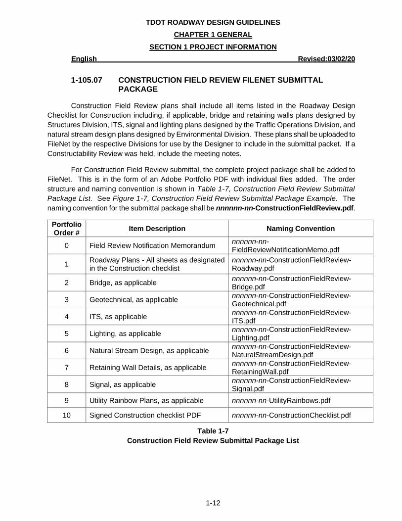
1-105.07 CONSTRUCTION FIELD REVIEW FILENET SUBMITTAL PACKAGE
Construction Field Review plans shall include all items listed in the Roadway Design
Checklist for Construction including, if applicable, bridge and retaining walls plans designed by
Structures Division, ITS, signal and lighting plans designed by the Traffic Operations Division, and
natural stream design plans designed by Environmental Division. These plans shall be uploaded to
FileNet by the respective Divisions for use by the Designer to include in the submittal packet. If a
Constructability Review was held, include the meeting notes.
For Construction Field Review submittal, the complete project package shall be added to
FileNet. This is in the form of an Adobe Portfolio PDF with individual files added. The order
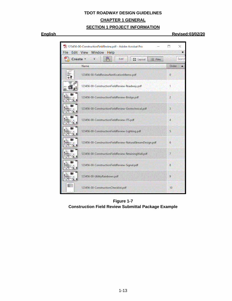
structure and naming convention is shown in Table 1-7, Construction Field Review Submittal
Package List. See Figure 1-7, Construction Field Review Submittal Package Example. The
naming convention for the submittal package shall be nnnnnn-nn-ConstructionFieldReview.pdf.
Portfolio Order #
Item Description Naming Convention
0 Field Review Notification Memorandum nnnnnn-nn-FieldReviewNotificationMemo.pdf
1 Roadway Plans - All sheets as designated in the Construction checklist
nnnnnn-nn-ConstructionFieldReview-Roadway.pdf
2 Bridge, as applicable nnnnnn-nn-ConstructionFieldReview-Bridge.pdf
3 Geotechnical, as applicable nnnnnn-nn-ConstructionFieldReview-Geotechnical.pdf
4 ITS, as applicable nnnnnn-nn-ConstructionFieldReview-ITS.pdf
5 Lighting, as applicable nnnnnn-nn-ConstructionFieldReview-Lighting.pdf
6 Natural Stream Design, as applicable nnnnnn-nn-ConstructionFieldReview-NaturalStreamDesign.pdf
7 Retaining Wall Details, as applicable nnnnnn-nn-ConstructionFieldReview-RetainingWall.pdf
8 Signal, as applicable nnnnnn-nn-ConstructionFieldReview-Signal.pdf
9 Utility Rainbow Plans, as applicable nnnnnn-nn-UtilityRainbows.pdf
10 Signed Construction checklist PDF nnnnnn-nn-ConstructionChecklist.pdf
Table 1-7
Construction Field Review Submittal Package List
TDOT ROADWAY DESIGN GUIDELINES
CHAPTER 1 GENERAL
SECTION 1 PROJECT INFORMATION
English Revised:03/02/20
1-13
Figure 1-7
Construction Field Review Submittal Package Example
TDOT ROADWAY DESIGN GUIDELINES
CHAPTER 1 GENERAL
SECTION 1 PROJECT INFORMATION
English Revised:03/02/20
1-14
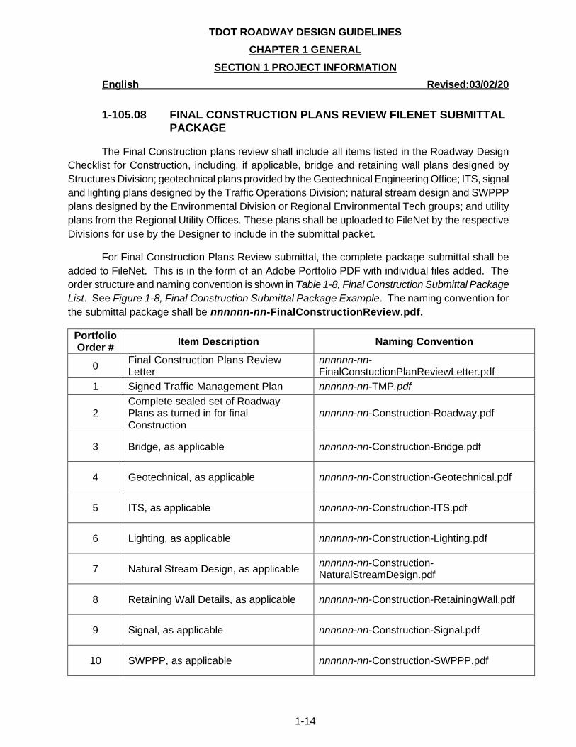
1-105.08 FINAL CONSTRUCTION PLANS REVIEW FILENET SUBMITTAL PACKAGE
The Final Construction plans review shall include all items listed in the Roadway Design
Checklist for Construction, including, if applicable, bridge and retaining wall plans designed by
Structures Division; geotechnical plans provided by the Geotechnical Engineering Office; ITS, signal
and lighting plans designed by the Traffic Operations Division; natural stream design and SWPPP
plans designed by the Environmental Division or Regional Environmental Tech groups; and utility
plans from the Regional Utility Offices. These plans shall be uploaded to FileNet by the respective
Divisions for use by the Designer to include in the submittal packet.
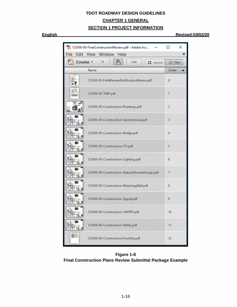
For Final Construction Plans Review submittal, the complete package submittal shall be
added to FileNet. This is in the form of an Adobe Portfolio PDF with individual files added. The
order structure and naming convention is shown in Table 1-8, Final Construction Submittal Package
List. See Figure 1-8, Final Construction Submittal Package Example. The naming convention for
the submittal package shall be nnnnnn-nn-FinalConstructionReview.pdf.
Portfolio Order #
Item Description Naming Convention
0 Final Construction Plans Review Letter
nnnnnn-nn-FinalConstuctionPlanReviewLetter.pdf
1 Signed Traffic Management Plan nnnnnn-nn-TMP.pdf
2 Complete sealed set of Roadway Plans as turned in for final Construction
nnnnnn-nn-Construction-Roadway.pdf
3 Bridge, as applicable nnnnnn-nn-Construction-Bridge.pdf
4 Geotechnical, as applicable nnnnnn-nn-Construction-Geotechnical.pdf
5 ITS, as applicable nnnnnn-nn-Construction-ITS.pdf
6 Lighting, as applicable nnnnnn-nn-Construction-Lighting.pdf
7 Natural Stream Design, as applicable nnnnnn-nn-Construction-NaturalStreamDesign.pdf
8 Retaining Wall Details, as applicable nnnnnn-nn-Construction-RetainingWall.pdf
9 Signal, as applicable nnnnnn-nn-Construction-Signal.pdf
10 SWPPP, as applicable nnnnnn-nn-Construction-SWPPP.pdf
TDOT ROADWAY DESIGN GUIDELINES
CHAPTER 1 GENERAL
SECTION 1 PROJECT INFORMATION
English Revised:03/02/20
1-15
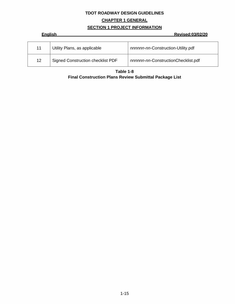
11 Utility Plans, as applicable nnnnnn-nn-Construction-Utility.pdf
12 Signed Construction checklist PDF nnnnnn-nn-ConstructionChecklist.pdf
Table 1-8
Final Construction Plans Review Submittal Package List
TDOT ROADWAY DESIGN GUIDELINES
CHAPTER 1 GENERAL
SECTION 1 PROJECT INFORMATION
English Revised:03/02/20
1-16
Figure 1-8
Final Construction Plans Review Submittal Package Example

TDOT ROADWAY DESIGN GUIDELINES
CHAPTER 1 GENERAL
SECTION 1 PROJECT INFORMATION
English Revised:03/02/20
1-17
1-105.09 CONSTRUCTION FILENET SUBMITTAL PACKAGE
Final Construction plans shall include all items listed in the Roadway Design Checklist for
Construction. Utility plans will be placed on FileNet by the Regional Utility Offices. Sealed
Structures plans will be placed on FileNet by the Structures Division personnel, including all bridge
sheets and all retaining wall sheets. Natural stream design and SWPPP plans will be placed on
FileNet by the Environmental Division personnel or Regional Environmental Tech groups.
Geotechnical Sheets will be placed on FileNet by the Geotechnical Engineering Section. Signal
Sheets and Lighting Sheets will be placed on FileNet by the Traffic Operations Division. Roadway
Design, Traffic Operations and Structures Standard Drawings are not required as part of the plans
submittal.
Resurfacing plans are not a traditional roadway project design. Their submittal will not
require a R.O.W. title sheet or a checklist, as these do not apply to this project type.
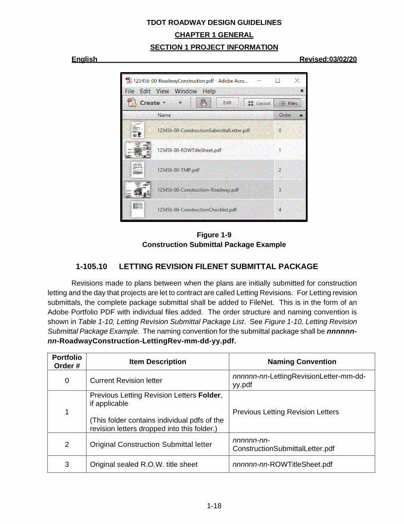
For final Construction submittal, the complete package submittal shall be added to FileNet.
This is in the form of an Adobe Portfolio PDF with individual files added. The order structure and
naming convention is shown in Table 1-9, Construction Submittal Package List. See Figure 1-9,
Construction Submittal Package Example. The naming convention for the submittal package shall
be nnnnnn-nn-RoadwayConstruction.pdf.
Portfolio Order #
Item Description Naming Convention
0 Construction Submittal letter
nnnnnn-nn-ConstructionSubmittalLetter.pdf
1 Original sealed R.O.W. title sheet nnnnnn-nn-ROWTitleSheet.pdf
2 Signed Traffic Management Plan nnnnnn-nn-TMP.pdf
3 Complete sealed set of Roadway Plans as turned in for final Construction
nnnnnn-nn-Construction-Roadway.pdf
4 Signed Construction checklist PDF nnnnnn-nn-ConstructionChecklist.pdf
Table 1-9
Construction Submittal Package List
TDOT ROADWAY DESIGN GUIDELINES
CHAPTER 1 GENERAL
SECTION 1 PROJECT INFORMATION
English Revised:03/02/20
1-18
Figure 1-9
Construction Submittal Package Example
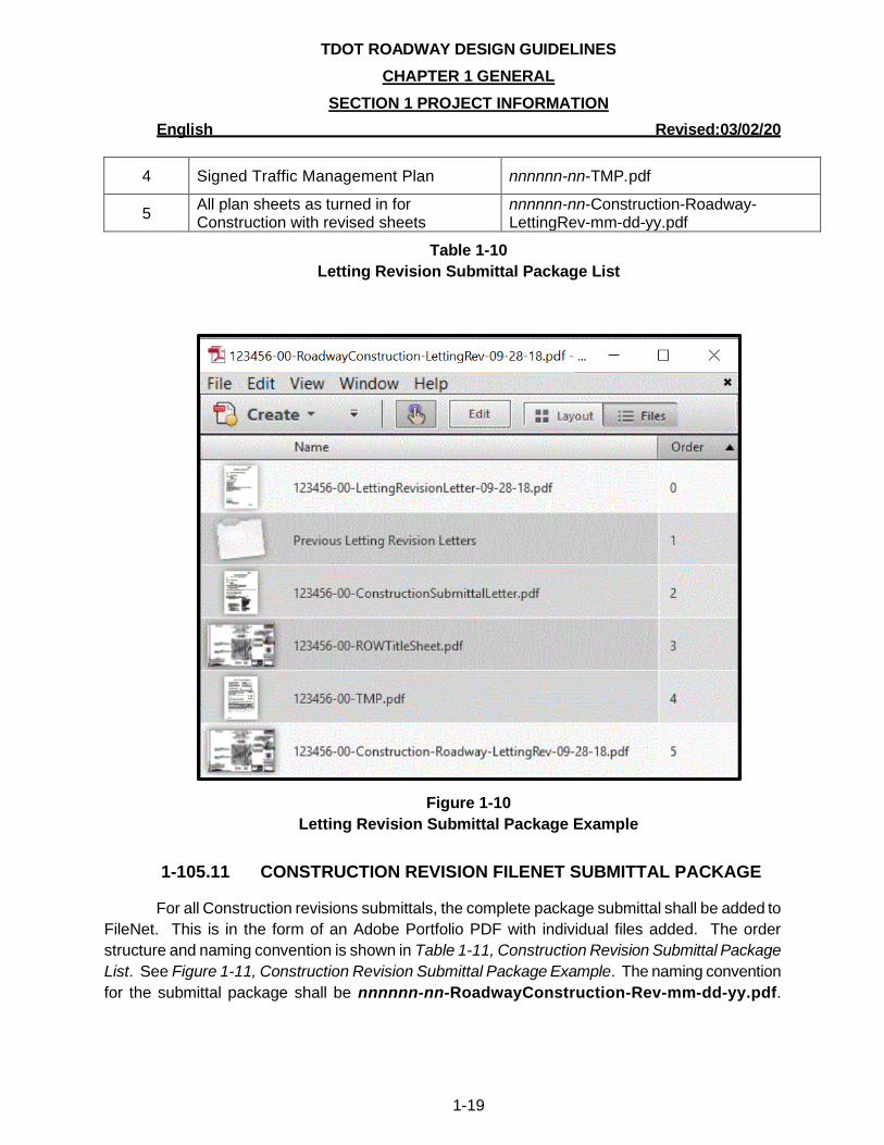
1-105.10 LETTING REVISION FILENET SUBMITTAL PACKAGE
Revisions made to plans between when the plans are initially submitted for construction
letting and the day that projects are let to contract are called Letting Revisions. For Letting revision
submittals, the complete package submittal shall be added to FileNet. This is in the form of an
Adobe Portfolio PDF with individual files added. The order structure and naming convention is
shown in Table 1-10, Letting Revision Submittal Package List. See Figure 1-10, Letting Revision
Submittal Package Example. The naming convention for the submittal package shall be nnnnnn-
nn-RoadwayConstruction-LettingRev-mm-dd-yy.pdf.
Portfolio Order #
Item Description Naming Convention
0 Current Revision letter nnnnnn-nn-LettingRevisionLetter-mm-dd-yy.pdf
1
Previous Letting Revision Letters Folder, if applicable (This folder contains individual pdfs of the revision letters dropped into this folder.)
Previous Letting Revision Letters
2 Original Construction Submittal letter nnnnnn-nn-ConstructionSubmittalLetter.pdf
3 Original sealed R.O.W. title sheet nnnnnn-nn-ROWTitleSheet.pdf
TDOT ROADWAY DESIGN GUIDELINES
CHAPTER 1 GENERAL
SECTION 1 PROJECT INFORMATION
English Revised:03/02/20
1-19
4 Signed Traffic Management Plan nnnnnn-nn-TMP.pdf
5 All plan sheets as turned in for Construction with revised sheets
nnnnnn-nn-Construction-Roadway-LettingRev-mm-dd-yy.pdf
Table 1-10
Letting Revision Submittal Package List
Figure 1-10
Letting Revision Submittal Package Example
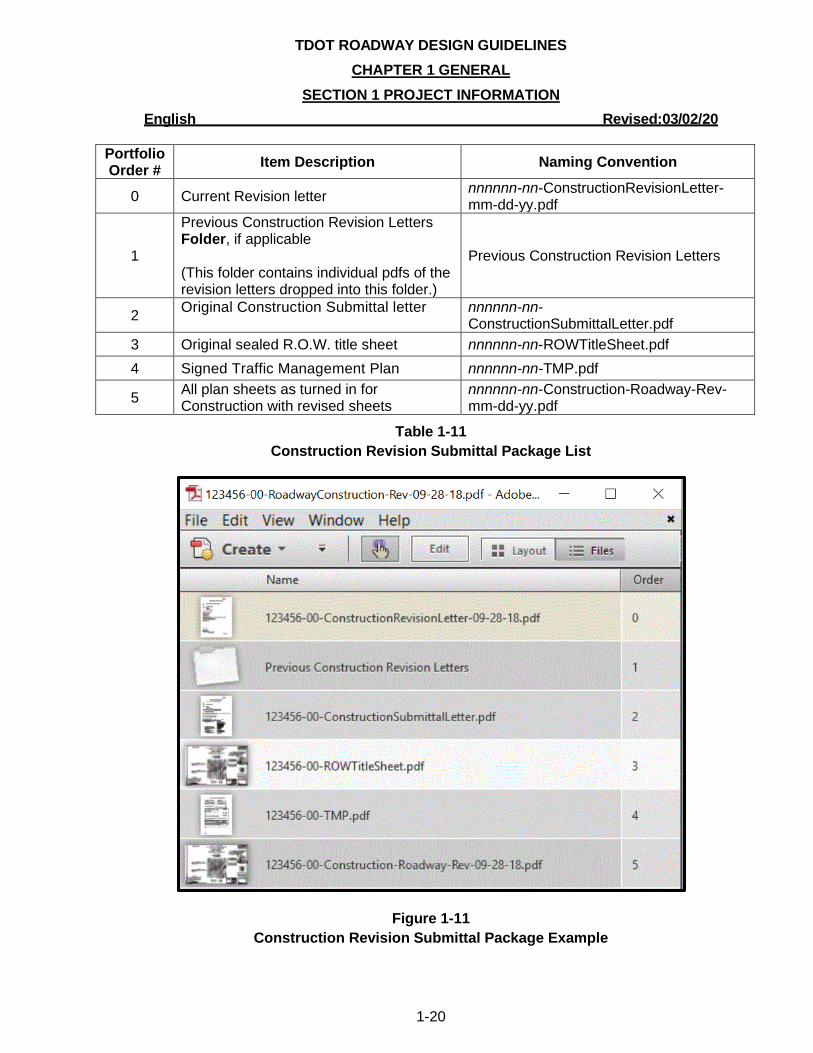
1-105.11 CONSTRUCTION REVISION FILENET SUBMITTAL PACKAGE
For all Construction revisions submittals, the complete package submittal shall be added to
FileNet. This is in the form of an Adobe Portfolio PDF with individual files added. The order
structure and naming convention is shown in Table 1-11, Construction Revision Submittal Package
List. See Figure 1-11, Construction Revision Submittal Package Example. The naming convention
for the submittal package shall be nnnnnn-nn-RoadwayConstruction-Rev-mm-dd-yy.pdf.
TDOT ROADWAY DESIGN GUIDELINES
CHAPTER 1 GENERAL
SECTION 1 PROJECT INFORMATION
English Revised:03/02/20
1-20
Portfolio Order #
Item Description Naming Convention
0 Current Revision letter nnnnnn-nn-ConstructionRevisionLetter-mm-dd-yy.pdf
1
Previous Construction Revision Letters Folder, if applicable (This folder contains individual pdfs of the revision letters dropped into this folder.)
Previous Construction Revision Letters
2 Original Construction Submittal letter
nnnnnn-nn-ConstructionSubmittalLetter.pdf
3 Original sealed R.O.W. title sheet nnnnnn-nn-ROWTitleSheet.pdf
4 Signed Traffic Management Plan nnnnnn-nn-TMP.pdf
5 All plan sheets as turned in for Construction with revised sheets
nnnnnn-nn-Construction-Roadway-Rev-mm-dd-yy.pdf
Table 1-11
Construction Revision Submittal Package List
Figure 1-11
Construction Revision Submittal Package Example
TDOT ROADWAY DESIGN GUIDELINES
CHAPTER 1 GENERAL
SECTION 1 PROJECT INFORMATION
English Revised:03/02/20
1-21
1-106.00 FILENET PROPERTIES
When a file is added to FileNet there are several properties associated with the project. It is
essential that each project have the properties filled in correctly for each deliverable and that the
properties do not vary on the same project. If there is a change on the project, such as the project
description, it is essential that the previously added properties for the project description be edited
to reflect the change.
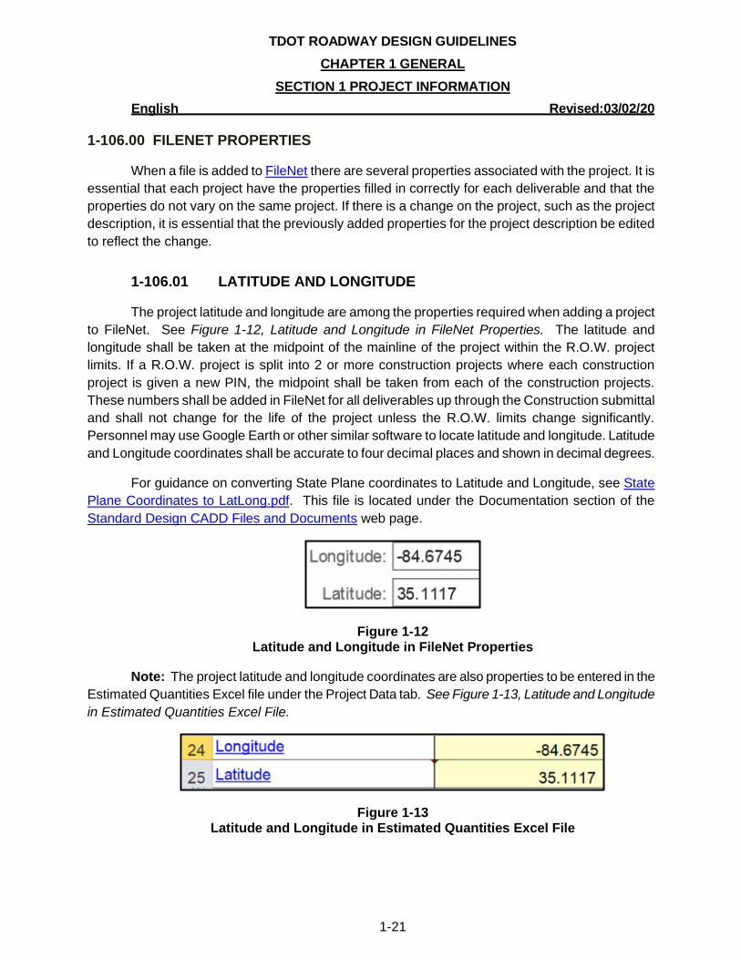
1-106.01 LATITUDE AND LONGITUDE
The project latitude and longitude are among the properties required when adding a project
to FileNet. See Figure 1-12, Latitude and Longitude in FileNet Properties. The latitude and
longitude shall be taken at the midpoint of the mainline of the project within the R.O.W. project
limits. If a R.O.W. project is split into 2 or more construction projects where each construction
project is given a new PIN, the midpoint shall be taken from each of the construction projects.
These numbers shall be added in FileNet for all deliverables up through the Construction submittal
and shall not change for the life of the project unless the R.O.W. limits change significantly.
Personnel may use Google Earth or other similar software to locate latitude and longitude. Latitude
and Longitude coordinates shall be accurate to four decimal places and shown in decimal degrees.
For guidance on converting State Plane coordinates to Latitude and Longitude, see State
Plane Coordinates to LatLong.pdf. This file is located under the Documentation section of the
Standard Design CADD Files and Documents web page.
Figure 1-12 Latitude and Longitude in FileNet Properties
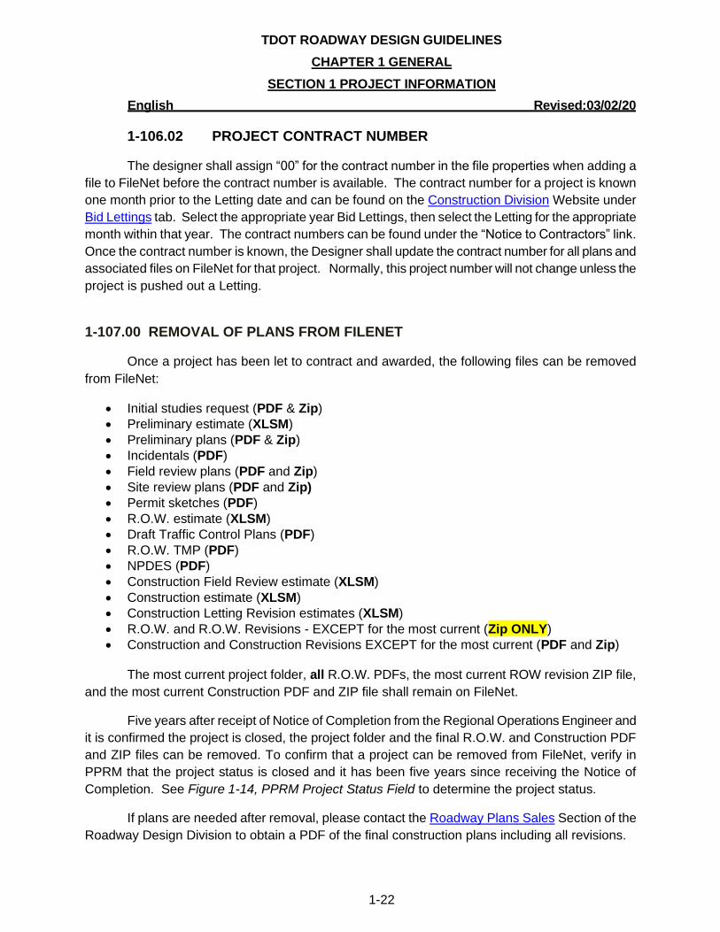
Note: The project latitude and longitude coordinates are also properties to be entered in the
Estimated Quantities Excel file under the Project Data tab. See Figure 1-13, Latitude and Longitude
in Estimated Quantities Excel File.
Figure 1-13 Latitude and Longitude in Estimated Quantities Excel File
TDOT ROADWAY DESIGN GUIDELINES
CHAPTER 1 GENERAL
SECTION 1 PROJECT INFORMATION
English Revised:03/02/20
1-22
1-106.02 PROJECT CONTRACT NUMBER
The designer shall assign “00” for the contract number in the file properties when adding a
file to FileNet before the contract number is available. The contract number for a project is known
one month prior to the Letting date and can be found on the Construction Division Website under
Bid Lettings tab. Select the appropriate year Bid Lettings, then select the Letting for the appropriate
month within that year. The contract numbers can be found under the “Notice to Contractors” link.
Once the contract number is known, the Designer shall update the contract number for all plans and
associated files on FileNet for that project. Normally, this project number will not change unless the
project is pushed out a Letting.
1-107.00 REMOVAL OF PLANS FROM FILENET
Once a project has been let to contract and awarded, the following files can be removed
from FileNet:
• Initial studies request (PDF & Zip)
• Preliminary estimate (XLSM)
• Preliminary plans (PDF & Zip)
• Incidentals (PDF)
• Field review plans (PDF and Zip)
• Site review plans (PDF and Zip)
• Permit sketches (PDF)
• R.O.W. estimate (XLSM)
• Draft Traffic Control Plans (PDF)
• R.O.W. TMP (PDF)
• NPDES (PDF)
• Construction Field Review estimate (XLSM)
• Construction estimate (XLSM)
• Construction Letting Revision estimates (XLSM)
• R.O.W. and R.O.W. Revisions - EXCEPT for the most current (Zip ONLY)
• Construction and Construction Revisions EXCEPT for the most current (PDF and Zip)
The most current project folder, all R.O.W. PDFs, the most current ROW revision ZIP file,
and the most current Construction PDF and ZIP file shall remain on FileNet.
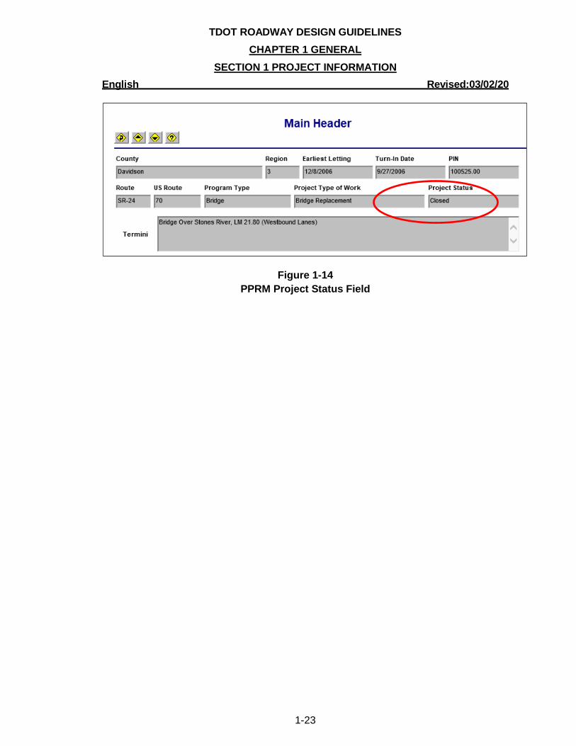
Five years after receipt of Notice of Completion from the Regional Operations Engineer and
it is confirmed the project is closed, the project folder and the final R.O.W. and Construction PDF
and ZIP files can be removed. To confirm that a project can be removed from FileNet, verify in
PPRM that the project status is closed and it has been five years since receiving the Notice of
Completion. See Figure 1-14, PPRM Project Status Field to determine the project status.
If plans are needed after removal, please contact the Roadway Plans Sales Section of the
Roadway Design Division to obtain a PDF of the final construction plans including all revisions.
TDOT ROADWAY DESIGN GUIDELINES
CHAPTER 1 GENERAL
SECTION 1 PROJECT INFORMATION
English Revised:03/02/20
1-23
Figure 1-14
PPRM Project Status Field
TDOT ROADWAY DESIGN GUIDELINES
CHAPTER 1 GENERAL
SECTION 2 PLANS PRODUCTION
English Revised:03/02/20
1-24
SECTION 2 – PLANS PRODUCTION
1-200.00 QUALITY ASSURANCE-QUALITY CONTROL
The goal of the TDOT Roadway Design Division Quality Assurance-Quality Control Section
is to perform an independent review of the plans by personnel not involved with the development
and design of the plans. This check is not intended to design the roadway and drainage
components of the project. Quality Assurance measures are created to ensure that roadway
Designers produce a quality set of plans that are complete, consistent across the state, and comply
with federal and state policies. Designers and Design Managers should check plans to ensure that
plans are accurate, constructible, cost effective and safe by conducting in-house checks and
holding field reviews with other divisions within TDOT. It is essential that all TDOT Divisions review
the plans and provide comments. If a division is absent, the Design Manager shall contact the
division to request comments. The following sections have been created to provide guidance for
plans development.
1-201.00 ROADWAY DESIGN CHECKLISTS
Roadway Design Checklists are provided for each stage of plan preparation to reduce errors
and plan revisions and to standardize the preparation, format, and content of plans. Checklists for
each submittal have been created to serve as a guide to ensure certain items are included on each
sheet of the plans. These checklists shall be used by all Designers, Consultants, and any personnel
checking plans. The Preliminary, Right of Way (R.O.W.), and Construction checklists are available
on the Roadway Design Guidelines webpage in the Reference Document area.
It is recommended that the Designer download each deliverable checklist for the current
phase of the project as opposed to downloading all checklists for each phase at once. This will
ensure the current checklist is downloaded. Prior to submitting plans for a field review, the checklist
shall be completed for that particular stage of plans development. The Designer shall submit the
completed and signed checklist when distributing the Field Review Notification by email for each
stage.
The Designer shall also refer to Project Development and Roadway Design activities listed
in Program/Project/Resource Management System (PPRM) to ensure that each plan set contains
deliverables from other divisions. PPRM is available from the transPORTAL website under
Business Applications.
Note: Resurfacing Plans are treated differently than other projects. Refer to Chapter 8,
Non-Traditional Projects, for information regarding Resurfacing projects.
TDOT ROADWAY DESIGN GUIDELINES
CHAPTER 1 GENERAL
SECTION 2 PLANS PRODUCTION
English Revised:03/02/20
1-25
1-202.00 PREPARATION OF PLAN SHEETS
The TDOT Survey and Roadway Design Computer–Aided Drafting and Design Standards
shall be followed by all divisions of TDOT, by Consultants, and by anyone conducting surveys or
producing plans for TDOT projects. This document, CADDV8.pdf, can be found at the Standard
Design CADD Files and Documents webpage in the Documentation section. The purpose of the
CADD document is to ensure consistency in MicroStation and GEOPAK files, correct file exchanges
between outside entities and the Department as well as within the division, and that printed and
archived files contain all necessary components and have the same appearance. Some of the most
important information found in the CADD document is the following:
• MicroStation
o File naming convention
o File extensions
o Seed files
o Color table
o Area patterning
o Text Size and Fonts
o Level filters including correct level name, line weight, line style, and color
o *Level structure according to sheet
o Office Templates for letters, 2nd sheets, and tabulated quantities
o Plan and Profile Sheet Production
o Cross Section Sheet Production
• GEOPAK
o GPK filenames
o Criteria Files
• Survey
o Project Filenames
o GPK filenames
o Data exchange between Survey and Project Development/Design personnel
o Aerial Survey Files
For each type of sheet (Present Layout, R.O.W. Details, Proposed Layout, Drainage Map, etc.),
a Sheet Level Structure is set up in MicroStation to turn on and off levels pertaining to the sheet
and reference files in the sheet. It is essential that each Surveyor or Designer use the correct
levels when placing data in design files that are referenced into the sheets so that the correct
attributes are shown when plotting.
Note: Users shall NOT turn on levels that are not part of the Sheet Level Structure if
requested to do so by another region or division. This negates the consistency of plans throughout
the state.
TDOT ROADWAY DESIGN GUIDELINES
CHAPTER 1 GENERAL
SECTION 2 PLANS PRODUCTION
English Revised:03/02/20
1-26
1-202.01 SHEET BORDERS
Sheet borders are available in MicroStation with a level structure that ensures the correct
area is printed and converted to PDF correctly for deliverables, printing, and archiving. Only TDOT
approved sheet borders shall be used by all divisions within TDOT and all outside Consultants,
utilities and others that are providing sheets to TDOT. To place a TDOT approved sheet border, the
TDOT menu must be available to the user in MicroStation.
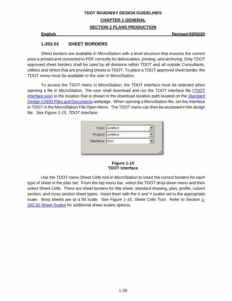
To access the TDOT menu in MicroStation, the TDOT interface must be selected when
opening a file in MicroStation. The user shall download and run the TDOT interface file (TDOT
interface.exe) to the location that is shown in the download location path located on the Standard
Design CADD Files and Documents webpage. When opening a MicroStation file, set the Interface
to TDOT in the MicroStation File Open Menu. The TDOT menu can then be accessed in the design
file. See Figure 1-15, TDOT Interface.
Figure 1-15 TDOT Interface
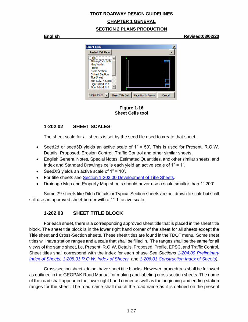
Use the TDOT menu Sheet Cells tool in MicroStation to insert the correct borders for each
type of sheet in the plan set. From the top menu bar, select the TDOT drop-down menu and then
select Sheet Cells. There are sheet borders for title sheet, standard drawing, plan, profile, culvert
section, and cross section sheet types. Insert them with the X and Y scales set to the appropriate
scale. Most sheets are at a 50 scale. See Figure 1-16, Sheet Cells Tool. Refer to Section 1-
202.02 Sheet Scales for additional sheet scales options.
TDOT ROADWAY DESIGN GUIDELINES
CHAPTER 1 GENERAL
SECTION 2 PLANS PRODUCTION
English Revised:03/02/20
1-27
Figure 1-16 Sheet Cells tool
1-202.02 SHEET SCALES
The sheet scale for all sheets is set by the seed file used to create that sheet.
• Seed2d or seed3D yields an active scale of 1” = 50’. This is used for Present, R.O.W.
Details, Proposed, Erosion Control, Traffic Control and other similar sheets.
• English General Notes, Special Notes, Estimated Quantities, and other similar sheets, and
Index and Standard Drawings cells each yield an active scale of 1” = 1’.
• SeedXS yields an active scale of 1” = 10’.
• For title sheets see Section 1-203.00 Development of Title Sheets.
• Drainage Map and Property Map sheets should never use a scale smaller than 1”:200’.
Some 2nd sheets like Ditch Details or Typical Section sheets are not drawn to scale but shall
still use an approved sheet border with a 1”-1’ active scale.
1-202.03 SHEET TITLE BLOCK
For each sheet, there is a corresponding approved sheet title that is placed in the sheet title
block. The sheet title block is in the lower right hand corner of the sheet for all sheets except the
Title sheet and Cross-Section sheets. These sheet titles are found in the TDOT menu. Some sheet
titles will have station ranges and a scale that shall be filled in. The ranges shall be the same for all
views of the same sheet, i.e. Present, R.O.W. Details, Proposed, Profile, EPSC, and Traffic Control.
Sheet titles shall correspond with the index for each phase See Sections 1-204.09 Preliminary
Index of Sheets, 1-205.01 R.O.W. Index of Sheets, and 1-206.01 Construction Index of Sheets).
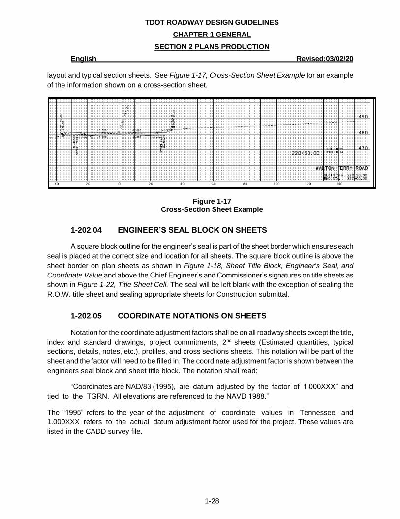
Cross section sheets do not have sheet title blocks. However, procedures shall be followed
as outlined in the GEOPAK Road Manual for making and labeling cross section sheets. The name
of the road shall appear in the lower right hand corner as well as the beginning and ending station
ranges for the sheet. The road name shall match the road name as it is defined on the present
TDOT ROADWAY DESIGN GUIDELINES
CHAPTER 1 GENERAL
SECTION 2 PLANS PRODUCTION
English Revised:03/02/20
1-28
layout and typical section sheets. See Figure 1-17, Cross-Section Sheet Example for an example
of the information shown on a cross-section sheet.
Figure 1-17 Cross-Section Sheet Example
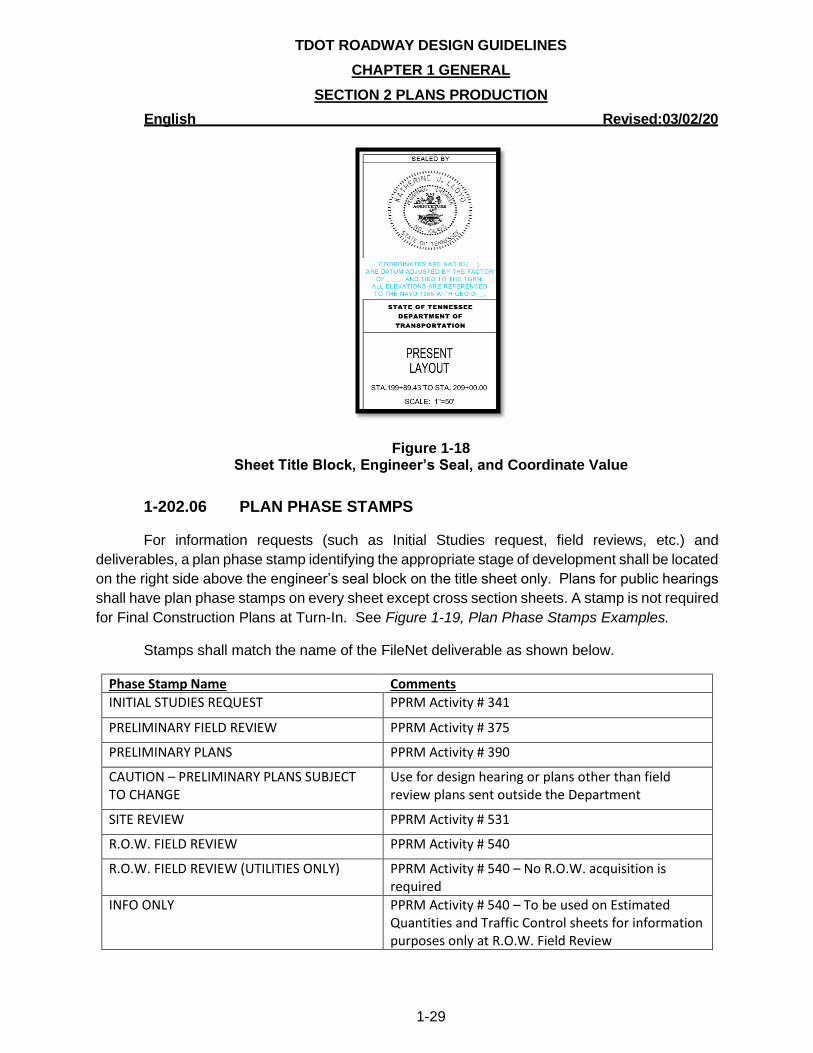
1-202.04 ENGINEER’S SEAL BLOCK ON SHEETS
A square block outline for the engineer’s seal is part of the sheet border which ensures each
seal is placed at the correct size and location for all sheets. The square block outline is above the
sheet border on plan sheets as shown in Figure 1-18, Sheet Title Block, Engineer’s Seal, and
Coordinate Value and above the Chief Engineer’s and Commissioner’s signatures on title sheets as
shown in Figure 1-22, Title Sheet Cell. The seal will be left blank with the exception of sealing the
R.O.W. title sheet and sealing appropriate sheets for Construction submittal.
1-202.05 COORDINATE NOTATIONS ON SHEETS
Notation for the coordinate adjustment factors shall be on all roadway sheets except the title,
index and standard drawings, project commitments, 2nd sheets (Estimated quantities, typical
sections, details, notes, etc.), profiles, and cross sections sheets. This notation will be part of the
sheet and the factor will need to be filled in. The coordinate adjustment factor is shown between the
engineers seal block and sheet title block. The notation shall read:
“Coordinates are NAD/83 (1995), are datum adjusted by the factor of 1.000XXX” and
tied to the TGRN. All elevations are referenced to the NAVD 1988.”
The “1995” refers to the year of the adjustment of coordinate values in Tennessee and
1.000XXX refers to the actual datum adjustment factor used for the project. These values are
listed in the CADD survey file.
TDOT ROADWAY DESIGN GUIDELINES
CHAPTER 1 GENERAL
SECTION 2 PLANS PRODUCTION
English Revised:03/02/20
1-29
Figure 1-18 Sheet Title Block, Engineer’s Seal, and Coordinate Value
1-202.06 PLAN PHASE STAMPS
For information requests (such as Initial Studies request, field reviews, etc.) and
deliverables, a plan phase stamp identifying the appropriate stage of development shall be located
on the right side above the engineer’s seal block on the title sheet only. Plans for public hearings
shall have plan phase stamps on every sheet except cross section sheets. A stamp is not required
for Final Construction Plans at Turn-In. See Figure 1-19, Plan Phase Stamps Examples.
Stamps shall match the name of the FileNet deliverable as shown below.
Phase Stamp Name Comments
INITIAL STUDIES REQUEST PPRM Activity # 341
PRELIMINARY FIELD REVIEW PPRM Activity # 375
PRELIMINARY PLANS PPRM Activity # 390
CAUTION – PRELIMINARY PLANS SUBJECT TO CHANGE
Use for design hearing or plans other than field review plans sent outside the Department
SITE REVIEW PPRM Activity # 531
R.O.W. FIELD REVIEW PPRM Activity # 540
R.O.W. FIELD REVIEW (UTILITIES ONLY) PPRM Activity # 540 – No R.O.W. acquisition is required
INFO ONLY PPRM Activity # 540 – To be used on Estimated Quantities and Traffic Control sheets for information purposes only at R.O.W. Field Review
TDOT ROADWAY DESIGN GUIDELINES
CHAPTER 1 GENERAL
SECTION 2 PLANS PRODUCTION
English Revised:03/02/20
1-30
R.O.W. PLANS PPRM Activity # 600
R.O.W. PLANS (UTILITIES ONLY) PPRM Activity # 600 – No R.O.W. acquisition is required
R.O.W. PLANS – PERMITS APPLICATION
CONSTRUCTABILITY REVIEW PPRM Activity # 690
CONSTRUCTION FIELD REVIEW PPRM Activity # 695
FINAL CONSTRUCTION PLANS REVIEW PPRM Activity # 710
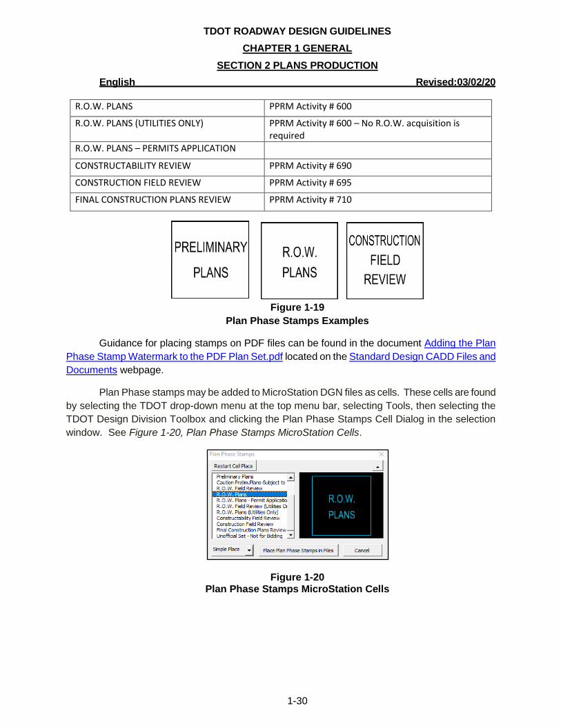
Figure 1-19
Plan Phase Stamps Examples
Guidance for placing stamps on PDF files can be found in the document Adding the Plan
Phase Stamp Watermark to the PDF Plan Set.pdf located on the Standard Design CADD Files and
Documents webpage.
Plan Phase stamps may be added to MicroStation DGN files as cells. These cells are found
by selecting the TDOT drop-down menu at the top menu bar, selecting Tools, then selecting the
TDOT Design Division Toolbox and clicking the Plan Phase Stamps Cell Dialog in the selection
window. See Figure 1-20, Plan Phase Stamps MicroStation Cells.
Figure 1-20 Plan Phase Stamps MicroStation Cells
TDOT ROADWAY DESIGN GUIDELINES
CHAPTER 1 GENERAL
SECTION 2 PLANS PRODUCTION
English Revised:03/02/20
1-31
1-203.00 DEVELOPMENT OF TITLE SHEETS
To ensure that all title sheets consistently have the same information, an all-inclusive title
sheet has been created with embedded cells that are needed for all phases of the title sheet. For
instructions on developing title sheets, users should download Title Sheet Preset Filters Tutorial,
which is under the Documentation section located on the Standard Design CADD Files and
Documents webpage.
Within MicroStation, a title sheet seed file is available that contains all necessary items for
the development of Preliminary, R.O.W., and Construction title sheets. If additional elements are
needed for creation of the sheet, cells are available in MicroStation within Sheet Cells in the TDOT
Menu. The title sheet is created with fillable texts that can be modified but will maintain the correct
text style and weight.
To access the TDOT menu in MicroStation, the TDOT interface must be available when
opening a file in MicroStation. See Section 1-202.01 for additional information.
Some of the information needed for the title sheet can be found in the
Program/Project/Resource Management System (PPRM). PPRM is available from the
transPORTAL website and only works with Internet Explorer. Consultant Designers should contact
their TDOT Design Manager for PPRM information.
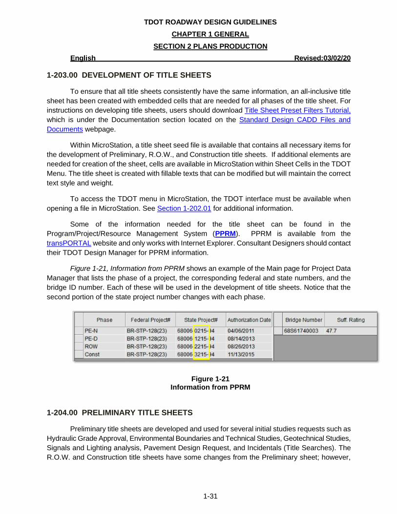
Figure 1-21, Information from PPRM shows an example of the Main page for Project Data
Manager that lists the phase of a project, the corresponding federal and state numbers, and the
bridge ID number. Each of these will be used in the development of title sheets. Notice that the
second portion of the state project number changes with each phase.
Figure 1-21 Information from PPRM
1-204.00 PRELIMINARY TITLE SHEETS
Preliminary title sheets are developed and used for several initial studies requests such as
Hydraulic Grade Approval, Environmental Boundaries and Technical Studies, Geotechnical Studies,
Signals and Lighting analysis, Pavement Design Request, and Incidentals (Title Searches). The
R.O.W. and Construction title sheets have some changes from the Preliminary sheet; however,
TDOT ROADWAY DESIGN GUIDELINES
CHAPTER 1 GENERAL
SECTION 2 PLANS PRODUCTION
English Revised:03/02/20
1-32
most components of the sheet are the same. Any that are different will be defined within the R.O.W.
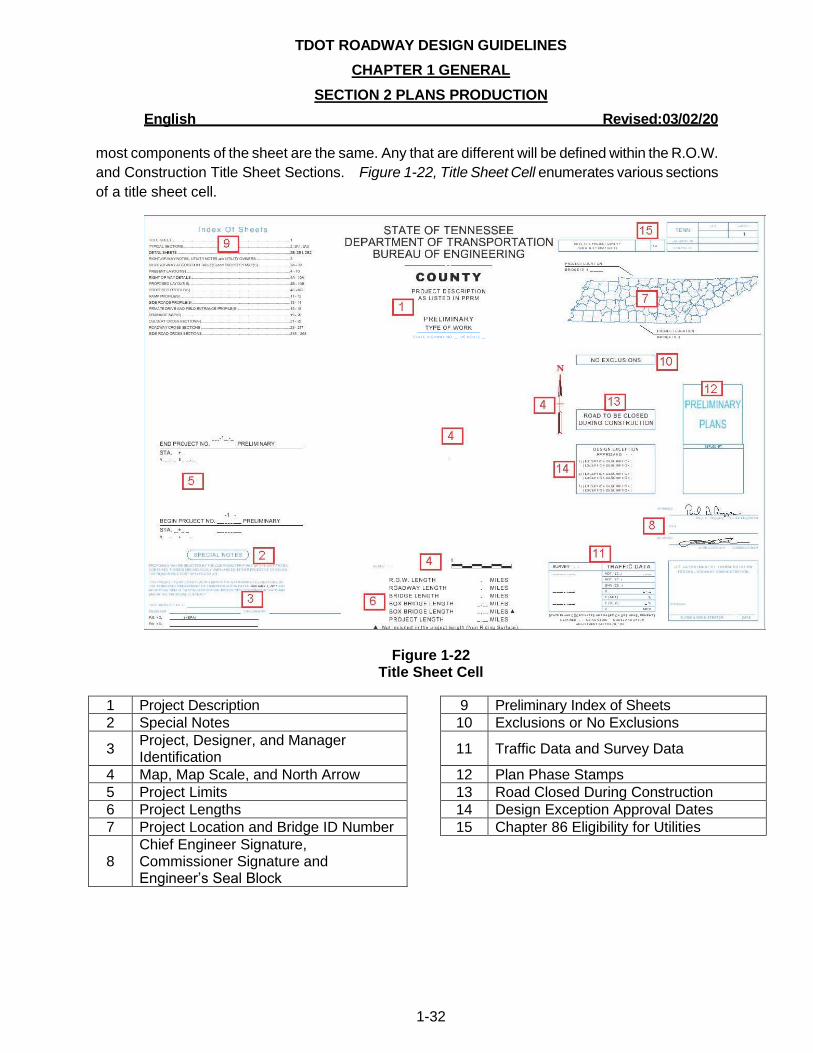
and Construction Title Sheet Sections. Figure 1-22, Title Sheet Cell enumerates various sections
of a title sheet cell.
Figure 1-22 Title Sheet Cell
1 Project Description 9 Preliminary Index of Sheets
2 Special Notes 10 Exclusions or No Exclusions
3 Project, Designer, and Manager Identification
11 Traffic Data and Survey Data
4 Map, Map Scale, and North Arrow 12 Plan Phase Stamps
5 Project Limits 13 Road Closed During Construction
6 Project Lengths 14 Design Exception Approval Dates
7 Project Location and Bridge ID Number 15 Chapter 86 Eligibility for Utilities
8 Chief Engineer Signature, Commissioner Signature and Engineer’s Seal Block
TDOT ROADWAY DESIGN GUIDELINES
CHAPTER 1 GENERAL
SECTION 2 PLANS PRODUCTION
English Revised:03/02/20
1-33
1-204.01 PROJECT DESCRIPTION
Project descriptions on the title sheet shall match descriptions as they are shown in PPRM:
• County(s)
• State route number (if a State route), U.S. route number (if a U.S. route), or Local road
name with Project Limits (from and to)
• Type of project (Preliminary, R.O.W., Construction)
• Type of work
• State Highway number (if applicable)
• US Route number (if applicable)
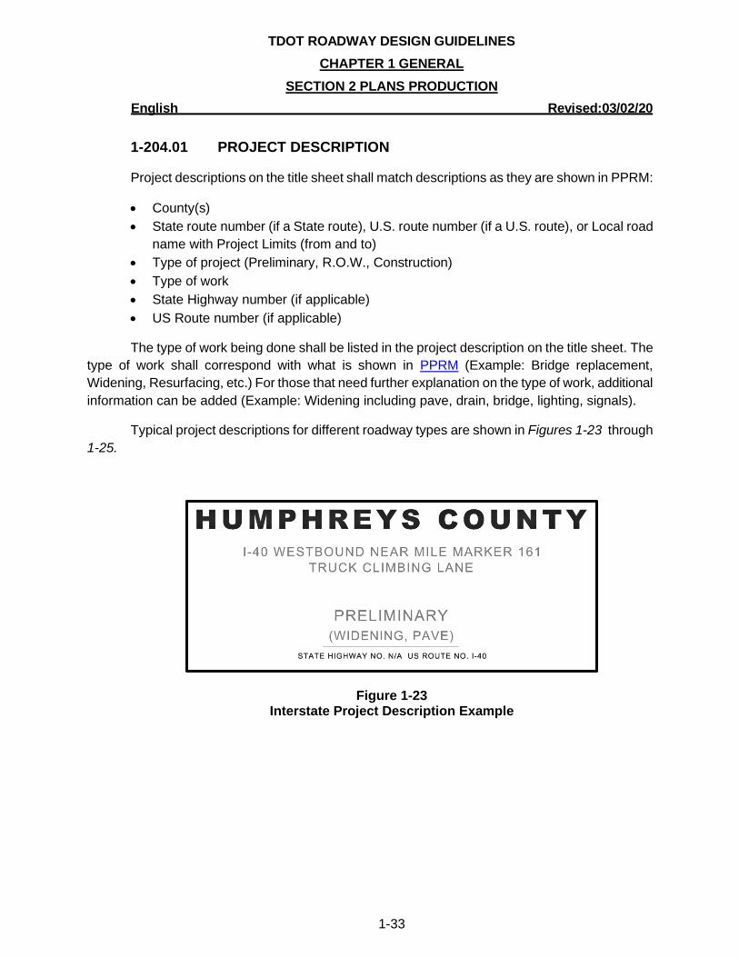
The type of work being done shall be listed in the project description on the title sheet. The
type of work shall correspond with what is shown in PPRM (Example: Bridge replacement,
Widening, Resurfacing, etc.) For those that need further explanation on the type of work, additional
information can be added (Example: Widening including pave, drain, bridge, lighting, signals).
Typical project descriptions for different roadway types are shown in Figures 1-23 through
1-25.
Figure 1-23 Interstate Project Description Example
TDOT ROADWAY DESIGN GUIDELINES
CHAPTER 1 GENERAL
SECTION 2 PLANS PRODUCTION
English Revised:03/02/20
1-34
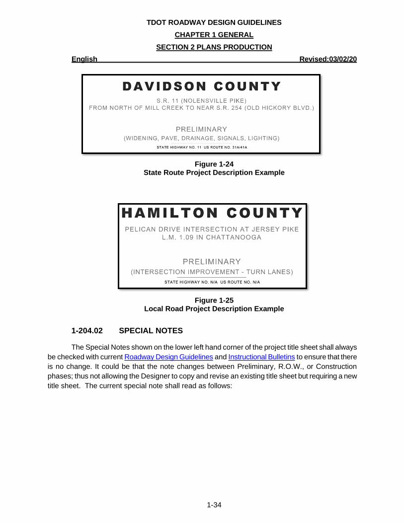
Figure 1-24
State Route Project Description Example
Figure 1-25
Local Road Project Description Example
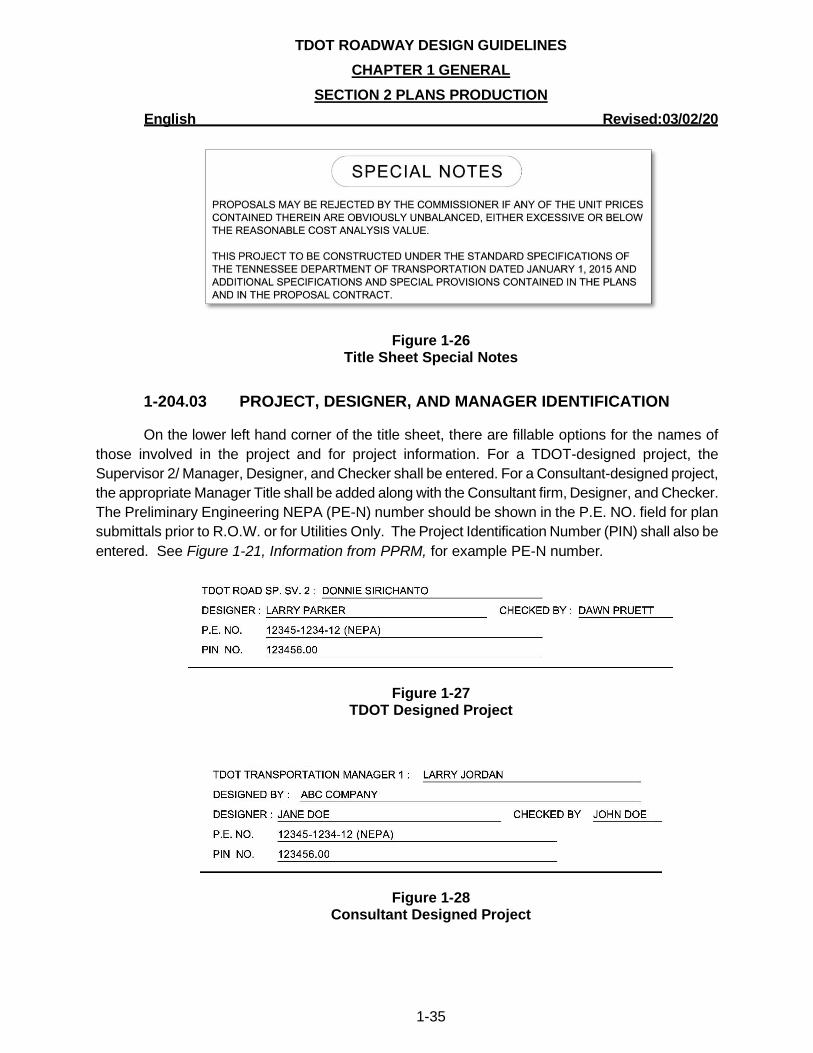
1-204.02 SPECIAL NOTES
The Special Notes shown on the lower left hand corner of the project title sheet shall always
be checked with current Roadway Design Guidelines and Instructional Bulletins to ensure that there
is no change. It could be that the note changes between Preliminary, R.O.W., or Construction
phases; thus not allowing the Designer to copy and revise an existing title sheet but requiring a new
title sheet. The current special note shall read as follows:
TDOT ROADWAY DESIGN GUIDELINES
CHAPTER 1 GENERAL
SECTION 2 PLANS PRODUCTION
English Revised:03/02/20
1-35
Figure 1-26 Title Sheet Special Notes
1-204.03 PROJECT, DESIGNER, AND MANAGER IDENTIFICATION
On the lower left hand corner of the title sheet, there are fillable options for the names of
those involved in the project and for project information. For a TDOT-designed project, the
Supervisor 2/ Manager, Designer, and Checker shall be entered. For a Consultant-designed project,
the appropriate Manager Title shall be added along with the Consultant firm, Designer, and Checker.
The Preliminary Engineering NEPA (PE-N) number should be shown in the P.E. NO. field for plan
submittals prior to R.O.W. or for Utilities Only. The Project Identification Number (PIN) shall also be
entered. See Figure 1-21, Information from PPRM, for example PE-N number.
Figure 1-27 TDOT Designed Project
Figure 1-28 Consultant Designed Project

TDOT ROADWAY DESIGN GUIDELINES
CHAPTER 1 GENERAL
SECTION 2 PLANS PRODUCTION
English Revised:03/02/20
1-36
1-204.04 MAP, MAP SCALE, AND NORTH ARROW
A location map for the project showing the route to be improved, local roads, streams,
railroads and towns shall be placed on the title sheet. Routes to major cities shall be labeled. See
Figure 1-22, Title Sheet Cell.
The map scale shall be 1”=5280’ and be placed below the map. The North arrow shall be shown beside the map. See Figure 1-29, Map, Map Scale, North Arrow, and Project Limits Example.
1-204.05 PROJECT LIMITS
The begin/end project limits shall be noted with federal and/or state project number,
corresponding project phase (R.O.W. or Const.), stations, and northing and easting coordinates
labeled to 4 decimal places. If the project has both federal and state project number, then both
federal and state projects numbers will be included in the begin/end project limits labels. On
Interstate plans, both Interstate log miles (based on Interstate mileposts) and stations will be required
when designating the beginning and ending points on all projects. See Figure 1-29, Map, Map Scale,
North Arrow, and Project Limits Example for an interstate example. Preliminary stations represent the
begin/end R.O.W. limits. If no R.O.W. is acquired, then use the Begin/End construction limits.
On state highway plans, such as resurfacing projects, when using log miles to designate the
beginning and ending points on projects, county log miles (mile posts) are to be used. The correct
log miles as shown in the PPRM description shall be referenced.
Figure 1-29 Map, Map Scale, North Arrow, and Project Limits Example
TDOT ROADWAY DESIGN GUIDELINES
CHAPTER 1 GENERAL
SECTION 2 PLANS PRODUCTION
English Revised:03/02/20
1-37
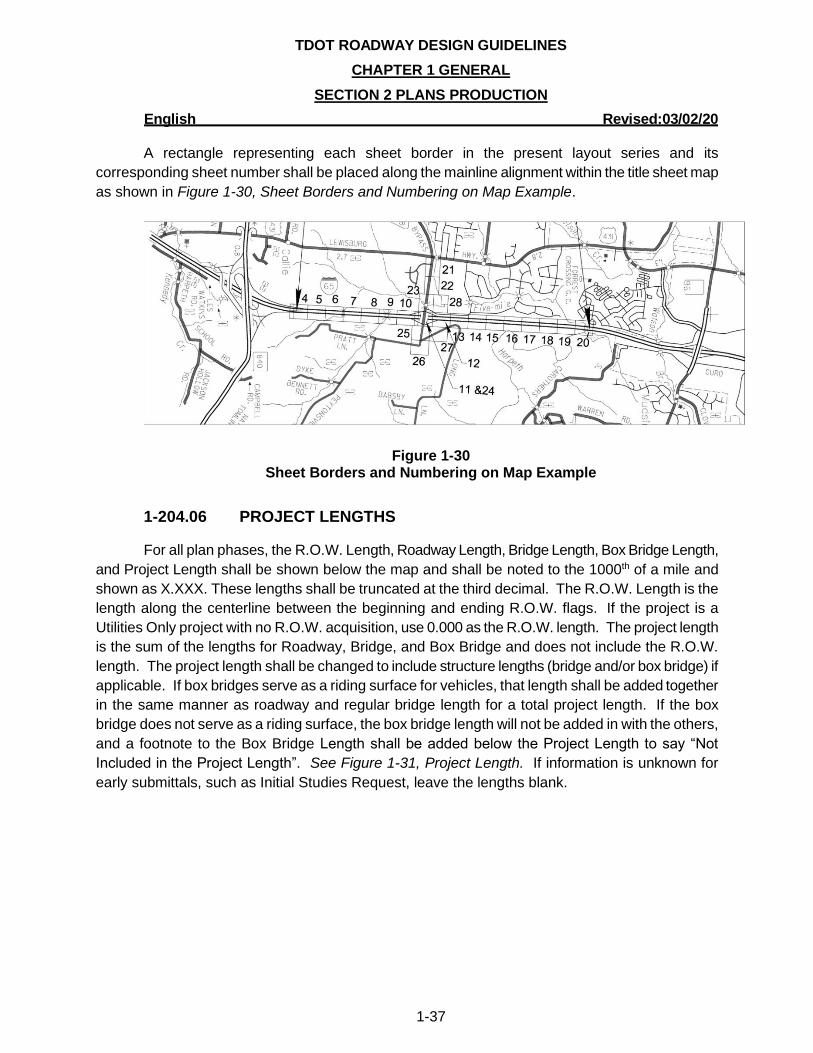
A rectangle representing each sheet border in the present layout series and its
corresponding sheet number shall be placed along the mainline alignment within the title sheet map
as shown in Figure 1-30, Sheet Borders and Numbering on Map Example.
Figure 1-30 Sheet Borders and Numbering on Map Example
1-204.06 PROJECT LENGTHS
For all plan phases, the R.O.W. Length, Roadway Length, Bridge Length, Box Bridge Length,
and Project Length shall be shown below the map and shall be noted to the 1000th of a mile and
shown as X.XXX. These lengths shall be truncated at the third decimal. The R.O.W. Length is the
length along the centerline between the beginning and ending R.O.W. flags. If the project is a
Utilities Only project with no R.O.W. acquisition, use 0.000 as the R.O.W. length. The project length
is the sum of the lengths for Roadway, Bridge, and Box Bridge and does not include the R.O.W.
length. The project length shall be changed to include structure lengths (bridge and/or box bridge) if
applicable. If box bridges serve as a riding surface for vehicles, that length shall be added together
in the same manner as roadway and regular bridge length for a total project length. If the box
bridge does not serve as a riding surface, the box bridge length will not be added in with the others,
and a footnote to the Box Bridge Length shall be added below the Project Length to say “Not
Included in the Project Length”. See Figure 1-31, Project Length. If information is unknown for
early submittals, such as Initial Studies Request, leave the lengths blank.
TDOT ROADWAY DESIGN GUIDELINES
CHAPTER 1 GENERAL
SECTION 2 PLANS PRODUCTION
English Revised:03/02/20
1-38
Figure 1-31 Project Length
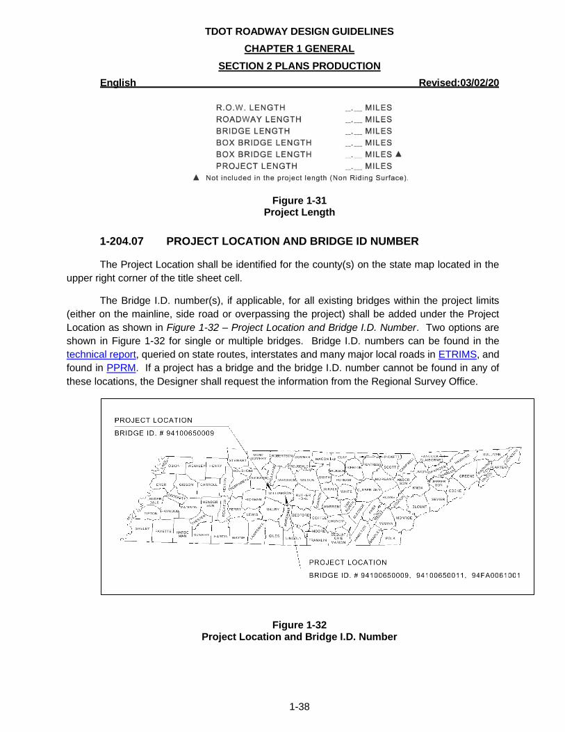
1-204.07 PROJECT LOCATION AND BRIDGE ID NUMBER
The Project Location shall be identified for the county(s) on the state map located in the
upper right corner of the title sheet cell.
The Bridge I.D. number(s), if applicable, for all existing bridges within the project limits
(either on the mainline, side road or overpassing the project) shall be added under the Project
Location as shown in Figure 1-32 – Project Location and Bridge I.D. Number. Two options are
shown in Figure 1-32 for single or multiple bridges. Bridge I.D. numbers can be found in the
technical report, queried on state routes, interstates and many major local roads in ETRIMS, and
found in PPRM. If a project has a bridge and the bridge I.D. number cannot be found in any of
these locations, the Designer shall request the information from the Regional Survey Office.
Figure 1-32
Project Location and Bridge I.D. Number
TDOT ROADWAY DESIGN GUIDELINES
CHAPTER 1 GENERAL
SECTION 2 PLANS PRODUCTION
English Revised:03/02/20
1-39
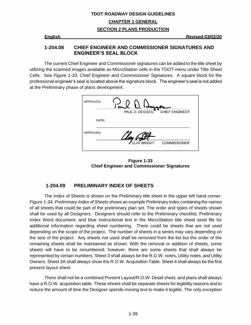
1-204.08 CHIEF ENGINEER AND COMMISSIONER SIGNATURES AND ENGINEER’S SEAL BLOCK
The current Chief Engineer and Commissioner signatures can be added to the title sheet by
utilizing the scanned images available as MicroStation cells in the TDOT menu under Title Sheet
Cells. See Figure 1-33, Chief Engineer and Commissioner Signatures. A square block for the
professional engineer’s seal is located above the signature block. The engineer’s seal is not added
at the Preliminary phase of plans development.
Figure 1-33 Chief Engineer and Commissioner Signatures
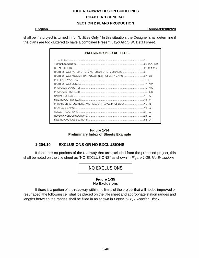
1-204.09 PRELIMINARY INDEX OF SHEETS
The Index of Sheets is shown on the Preliminary title sheet in the upper left hand corner.
Figure 1-34, Preliminary Index of Sheets shows an example Preliminary index containing the names
of all sheets that could be part of the preliminary plan set. The order and types of sheets shown
shall be used by all Designers. Designers should refer to the Preliminary checklist, Preliminary
Index Word document, and blue instructional text in the MicroStation title sheet seed file for
additional information regarding sheet numbering. There could be sheets that are not used
depending on the scope of the project. The number of sheets in a series may vary depending on
the size of the project. Any sheets not used shall be removed from the list but the order of the
remaining sheets shall be maintained as shown. With the removal or addition of sheets, some
sheets will have to be renumbered; however, there are some sheets that shall always be
represented by certain numbers. Sheet 3 shall always be the R.O.W. notes, Utility notes, and Utility
Owners. Sheet 3A shall always show the R.O.W. Acquisition Table. Sheet 4 shall always be the first
present layout sheet.
There shall not be a combined Present Layout/R.O.W. Detail sheet, and plans shall always
have a R.O.W. acquisition table. These sheets shall be separate sheets for legibility reasons and to
reduce the amount of time the Designer spends moving text to make it legible. The only exception
TDOT ROADWAY DESIGN GUIDELINES
CHAPTER 1 GENERAL
SECTION 2 PLANS PRODUCTION
English Revised:03/02/20
1-40
shall be if a project is turned in for “Utilities Only.” In this situation, the Designer shall determine if
the plans are too cluttered to have a combined Present Layout/R.O.W. Detail sheet.
Figure 1-34 Preliminary Index of Sheets Example
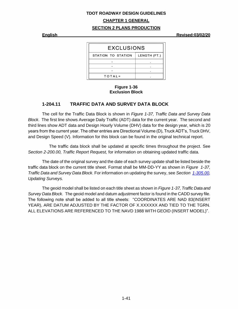
1-204.10 EXCLUSIONS OR NO EXCLUSIONS
If there are no portions of the roadway that are excluded from the proposed project, this
shall be noted on the title sheet as “NO EXCLUSIONS” as shown in Figure 1-35, No Exclusions.
Figure 1-35 No Exclusions
If there is a portion of the roadway within the limits of the project that will not be improved or
resurfaced, the following cell shall be placed on the title sheet and appropriate station ranges and
lengths between the ranges shall be filled in as shown in Figure 1-36, Exclusion Block.
TDOT ROADWAY DESIGN GUIDELINES
CHAPTER 1 GENERAL
SECTION 2 PLANS PRODUCTION
English Revised:03/02/20
1-41
Figure 1-36 Exclusion Block
1-204.11 TRAFFIC DATA AND SURVEY DATA BLOCK
The cell for the Traffic Data Block is shown in Figure 1-37, Traffic Data and Survey Data
Block. The first line shows Average Daily Traffic (ADT) data for the current year. The second and
third lines show ADT data and Design Hourly Volume (DHV) data for the design year, which is 20
years from the current year. The other entries are Directional Volume (D), Truck ADT’s, Truck DHV,
and Design Speed (V). Information for this block can be found in the original technical report.
The traffic data block shall be updated at specific times throughout the project. See
Section 2-200.00, Traffic Report Request, for information on obtaining updated traffic data.
The date of the original survey and the date of each survey update shall be listed beside the
traffic data block on the current title sheet. Format shall be MM-DD-YY as shown in Figure 1-37,
Traffic Data and Survey Data Block. For information on updating the survey, see Section 1-305.00,
Updating Surveys.
The geoid model shall be listed on each title sheet as shown in Figure 1-37, Traffic Data and
Survey Data Block. The geoid model and datum adjustment factor is found in the CADD survey file.
The following note shall be added to all title sheets: “COORDINATES ARE NAD 83(INSERT
YEAR), ARE DATUM ADJUSTED BY THE FACTOR OF X.XXXXXX AND TIED TO THE TGRN.
ALL ELEVATIONS ARE REFERENCED TO THE NAVD 1988 WITH GEOID (INSERT MODEL)”.

TDOT ROADWAY DESIGN GUIDELINES
CHAPTER 1 GENERAL
SECTION 2 PLANS PRODUCTION
English Revised:03/02/20
1-42
Figure 1-37 Traffic Data and Survey Data Block
1-204.12 PLAN PHASE STAMPS
See Section 1-202.06, Plan Phase Stamps, for more details on the appropriate plan phase
stamp to use. For preliminary plans, use the phase stamp shown in Figure 1-22, Title Sheet Cell.
Phase Stamp Name Comments
INITIAL STUDIES REQUEST PPRM Activity # 341
PRELIMINARY FIELD REVIEW PPRM Activity # 375
PRELIMINARY PLANS
CAUTION – PRELIMINARY PLANS SUBJECT TO CHANGE
Use for design hearing or plans other than field review plans sent outside the Department
SITE REVIEW PPRM Activity # 531
R.O.W. FIELD REVIEW PPRM Activity # 540
R.O.W. FIELD REVIEW (UTILITIES ONLY) PPRM Activity # 540 – No R.O.W. acquisition is required
INFO ONLY PPRM Activity # 540 – To be used on Estimated Quantities and Traffic Control sheets for information purposes only at R.O.W. Field Review
R.O.W. PLANS PPRM Activity # 600
R.O.W. PLANS (UTILITIES ONLY) PPRM Activity # 600 – No R.O.W. acquisition is required
CONSTRUCTABILITY REVIEW PPRM Activity # 690
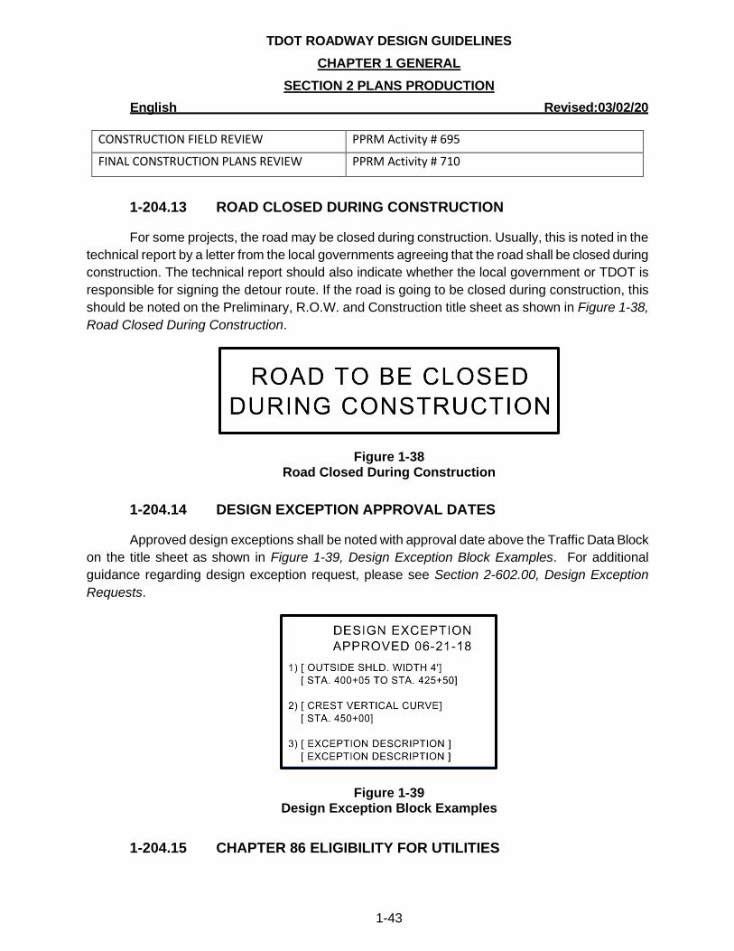
TDOT ROADWAY DESIGN GUIDELINES
CHAPTER 1 GENERAL
SECTION 2 PLANS PRODUCTION
English Revised:03/02/20
1-43
CONSTRUCTION FIELD REVIEW PPRM Activity # 695
FINAL CONSTRUCTION PLANS REVIEW PPRM Activity # 710
1-204.13 ROAD CLOSED DURING CONSTRUCTION
For some projects, the road may be closed during construction. Usually, this is noted in the
technical report by a letter from the local governments agreeing that the road shall be closed during
construction. The technical report should also indicate whether the local government or TDOT is
responsible for signing the detour route. If the road is going to be closed during construction, this
should be noted on the Preliminary, R.O.W. and Construction title sheet as shown in Figure 1-38,
Road Closed During Construction.
Figure 1-38 Road Closed During Construction
1-204.14 DESIGN EXCEPTION APPROVAL DATES
Approved design exceptions shall be noted with approval date above the Traffic Data Block
on the title sheet as shown in Figure 1-39, Design Exception Block Examples. For additional
guidance regarding design exception request, please see Section 2-602.00, Design Exception
Requests.
Figure 1-39 Design Exception Block Examples
1-204.15 CHAPTER 86 ELIGIBILITY FOR UTILITIES
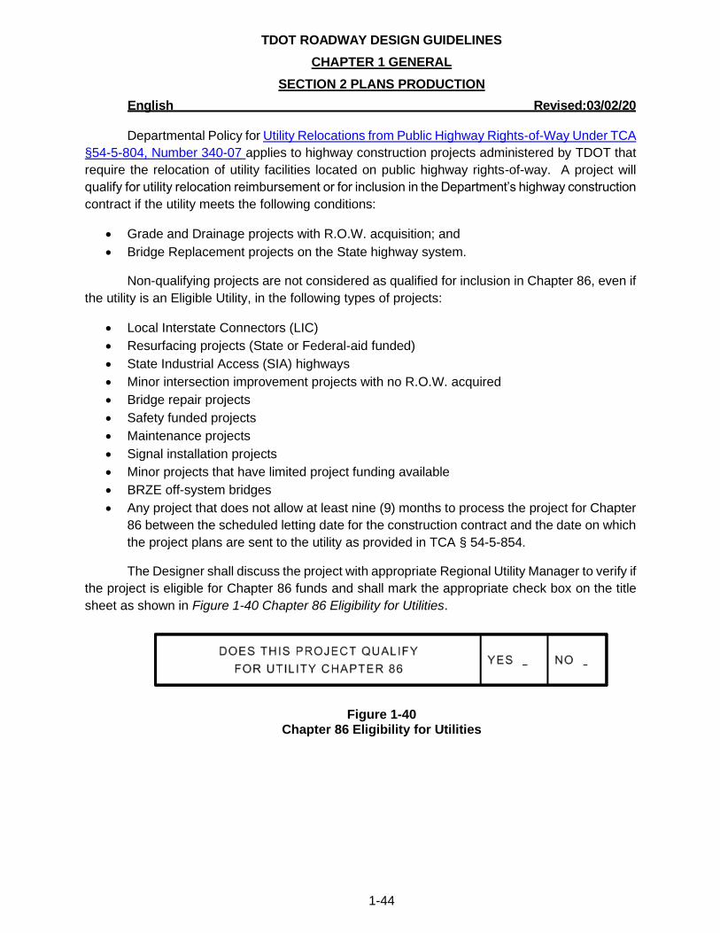
TDOT ROADWAY DESIGN GUIDELINES
CHAPTER 1 GENERAL
SECTION 2 PLANS PRODUCTION
English Revised:03/02/20
1-44
Departmental Policy for Utility Relocations from Public Highway Rights-of-Way Under TCA
§54-5-804, Number 340-07 applies to highway construction projects administered by TDOT that
require the relocation of utility facilities located on public highway rights-of-way. A project will
qualify for utility relocation reimbursement or for inclusion in the Department’s highway construction
contract if the utility meets the following conditions:
• Grade and Drainage projects with R.O.W. acquisition; and
• Bridge Replacement projects on the State highway system.
Non-qualifying projects are not considered as qualified for inclusion in Chapter 86, even if
the utility is an Eligible Utility, in the following types of projects:
• Local Interstate Connectors (LIC)
• Resurfacing projects (State or Federal-aid funded)
• State Industrial Access (SIA) highways
• Minor intersection improvement projects with no R.O.W. acquired
• Bridge repair projects
• Safety funded projects
• Maintenance projects
• Signal installation projects
• Minor projects that have limited project funding available
• BRZE off-system bridges
• Any project that does not allow at least nine (9) months to process the project for Chapter
86 between the scheduled letting date for the construction contract and the date on which
the project plans are sent to the utility as provided in TCA § 54-5-854.
The Designer shall discuss the project with appropriate Regional Utility Manager to verify if
the project is eligible for Chapter 86 funds and shall mark the appropriate check box on the title
sheet as shown in Figure 1-40 Chapter 86 Eligibility for Utilities.
Figure 1-40 Chapter 86 Eligibility for Utilities
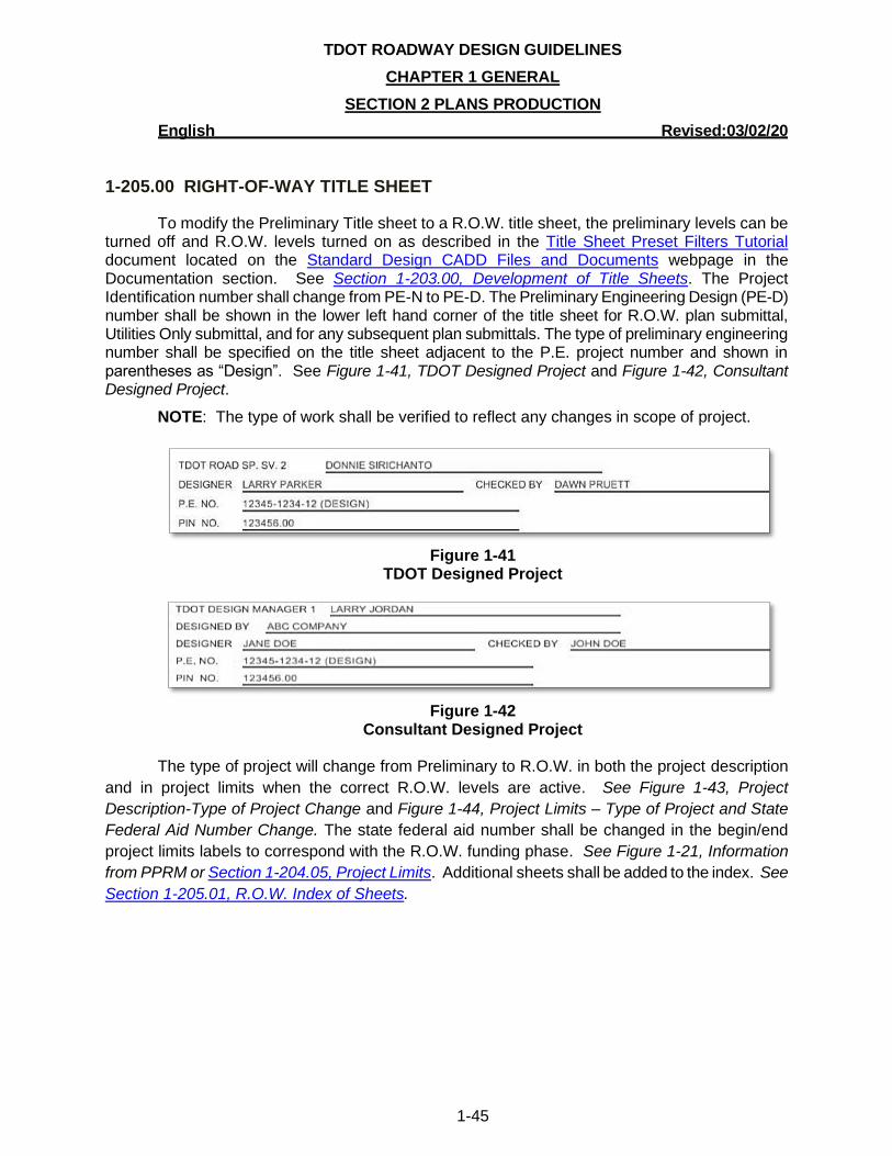
TDOT ROADWAY DESIGN GUIDELINES
CHAPTER 1 GENERAL
SECTION 2 PLANS PRODUCTION
English Revised:03/02/20
1-45
1-205.00 RIGHT-OF-WAY TITLE SHEET
To modify the Preliminary Title sheet to a R.O.W. title sheet, the preliminary levels can be turned off and R.O.W. levels turned on as described in the Title Sheet Preset Filters Tutorial document located on the Standard Design CADD Files and Documents webpage in the Documentation section. See Section 1-203.00, Development of Title Sheets. The Project Identification number shall change from PE-N to PE-D. The Preliminary Engineering Design (PE-D) number shall be shown in the lower left hand corner of the title sheet for R.O.W. plan submittal, Utilities Only submittal, and for any subsequent plan submittals. The type of preliminary engineering number shall be specified on the title sheet adjacent to the P.E. project number and shown in parentheses as “Design”. See Figure 1-41, TDOT Designed Project and Figure 1-42, Consultant Designed Project.
NOTE: The type of work shall be verified to reflect any changes in scope of project.
Figure 1-41
TDOT Designed Project
Figure 1-42
Consultant Designed Project
The type of project will change from Preliminary to R.O.W. in both the project description
and in project limits when the correct R.O.W. levels are active. See Figure 1-43, Project
Description-Type of Project Change and Figure 1-44, Project Limits – Type of Project and State
Federal Aid Number Change. The state federal aid number shall be changed in the begin/end
project limits labels to correspond with the R.O.W. funding phase. See Figure 1-21, Information
from PPRM or Section 1-204.05, Project Limits. Additional sheets shall be added to the index. See
Section 1-205.01, R.O.W. Index of Sheets.
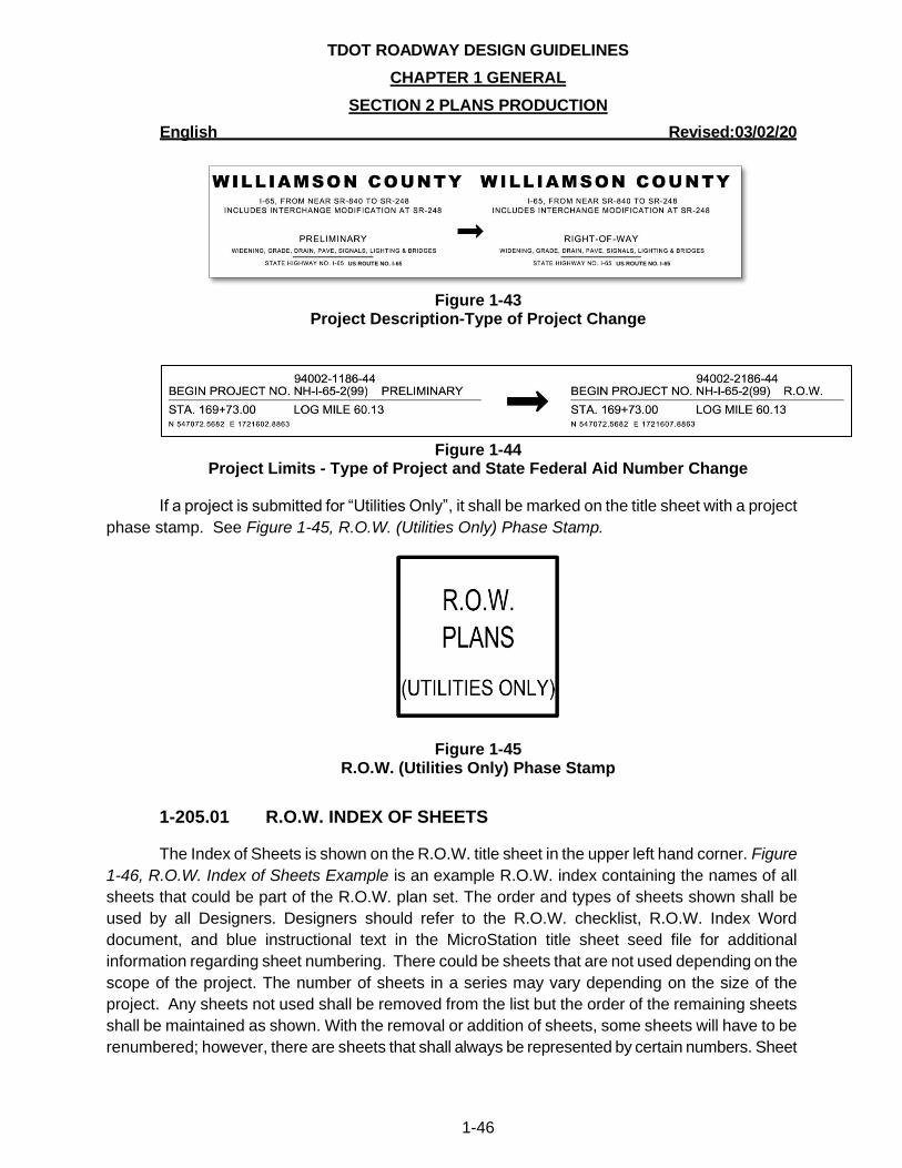
TDOT ROADWAY DESIGN GUIDELINES
CHAPTER 1 GENERAL
SECTION 2 PLANS PRODUCTION
English Revised:03/02/20
1-46
Figure 1-43
Project Description-Type of Project Change
Figure 1-44
Project Limits - Type of Project and State Federal Aid Number Change
If a project is submitted for “Utilities Only”, it shall be marked on the title sheet with a project
phase stamp. See Figure 1-45, R.O.W. (Utilities Only) Phase Stamp.
Figure 1-45 R.O.W. (Utilities Only) Phase Stamp
1-205.01 R.O.W. INDEX OF SHEETS
The Index of Sheets is shown on the R.O.W. title sheet in the upper left hand corner. Figure
1-46, R.O.W. Index of Sheets Example is an example R.O.W. index containing the names of all
sheets that could be part of the R.O.W. plan set. The order and types of sheets shown shall be
used by all Designers. Designers should refer to the R.O.W. checklist, R.O.W. Index Word
document, and blue instructional text in the MicroStation title sheet seed file for additional
information regarding sheet numbering. There could be sheets that are not used depending on the
scope of the project. The number of sheets in a series may vary depending on the size of the
project. Any sheets not used shall be removed from the list but the order of the remaining sheets
shall be maintained as shown. With the removal or addition of sheets, some sheets will have to be
renumbered; however, there are sheets that shall always be represented by certain numbers. Sheet
US ROUTE NO. I-65 US ROUTE NO. I-65
TDOT ROADWAY DESIGN GUIDELINES
CHAPTER 1 GENERAL
SECTION 2 PLANS PRODUCTION
English Revised:03/02/20
1-47
3 shall always be the R.O.W. notes, Utility notes, and Utility Owners. Sheet 3A shall always show
the R.O.W. Acquisition Table. Sheet 4 shall always be the first present layout sheet.
There shall not be a combined Present Layout/R.O.W. Detail sheet, and plans shall always
have a R.O.W. acquisition table. These sheets shall be separate sheets for legibility reasons and to
reduce the amount of time the Designer spends moving text to make it legible. The only exception
shall be if a project is turned in for “Utilities Only.” In this situation, the Designer shall determine if
the plans are too cluttered to have a combined Present Layout/R.O.W. Detail sheet.
As plans progress, there will be additional sheets added for the Construction phase that
were not in the R.O.W. submittal. When plans are turned in for Construction, the original
R.O.W. sheet numbers shall remain as they were when turned in for R.O.W. and shall not be
altered to match construction sheet numbers.
Other Divisions that are developing their own sheets to add to the plan set should follow
the naming convention shown in Figure 1-46, R.O.W. Index of Sheets Example. The first sheet
of their series, *-1, should contain an index for the rest of the sheets in that series.
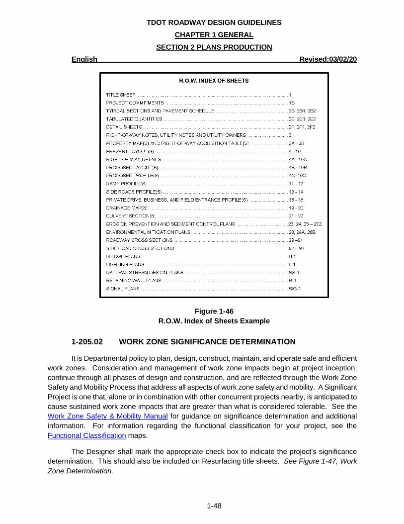
TDOT ROADWAY DESIGN GUIDELINES
CHAPTER 1 GENERAL
SECTION 2 PLANS PRODUCTION
English Revised:03/02/20
1-48
Figure 1-46
R.O.W. Index of Sheets Example
1-205.02 WORK ZONE SIGNIFICANCE DETERMINATION
It is Departmental policy to plan, design, construct, maintain, and operate safe and efficient
work zones. Consideration and management of work zone impacts begin at project inception,
continue through all phases of design and construction, and are reflected through the Work Zone
Safety and Mobility Process that address all aspects of work zone safety and mobility. A Significant
Project is one that, alone or in combination with other concurrent projects nearby, is anticipated to
cause sustained work zone impacts that are greater than what is considered tolerable. See the
Work Zone Safety & Mobility Manual for guidance on significance determination and additional
information. For information regarding the functional classification for your project, see the
Functional Classification maps.
The Designer shall mark the appropriate check box to indicate the project’s significance
determination. This should also be included on Resurfacing title sheets. See Figure 1-47, Work
Zone Determination.
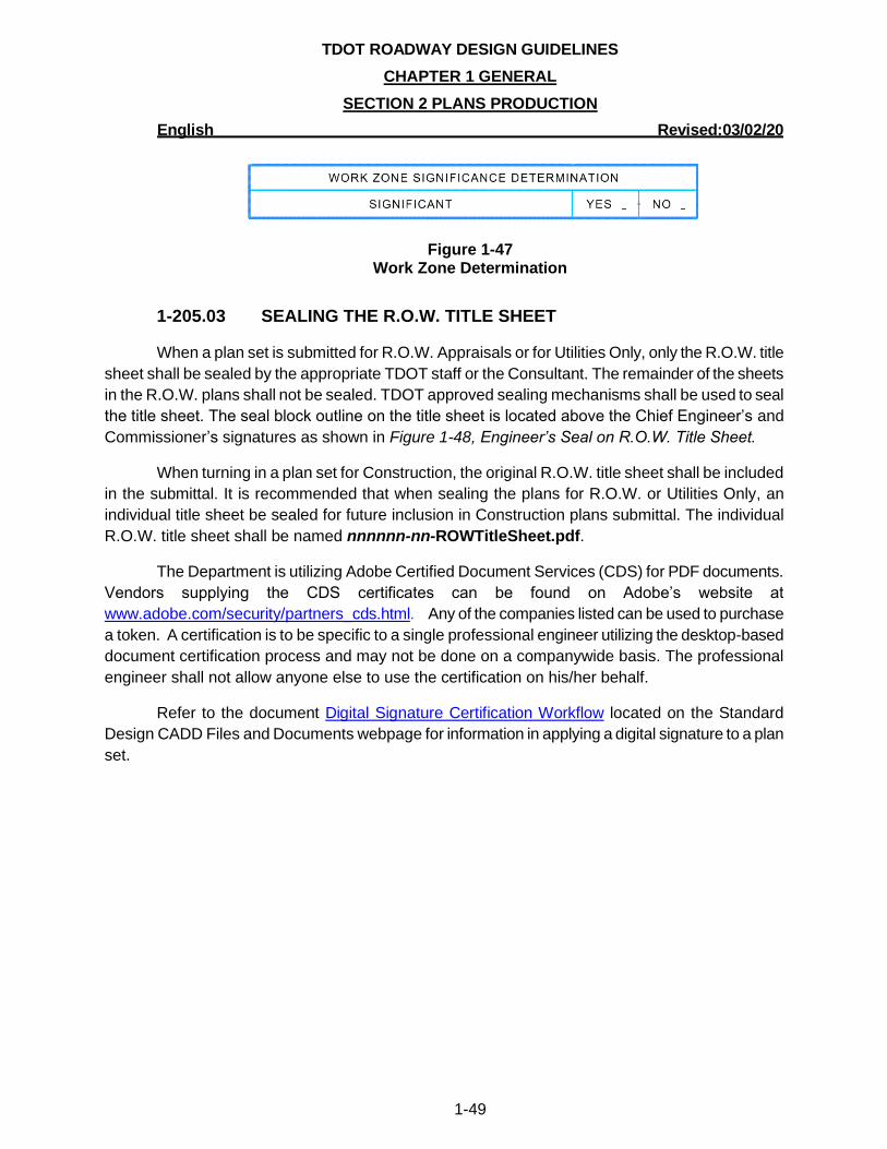
TDOT ROADWAY DESIGN GUIDELINES
CHAPTER 1 GENERAL
SECTION 2 PLANS PRODUCTION
English Revised:03/02/20
1-49
Figure 1-47 Work Zone Determination
1-205.03 SEALING THE R.O.W. TITLE SHEET
When a plan set is submitted for R.O.W. Appraisals or for Utilities Only, only the R.O.W. title
sheet shall be sealed by the appropriate TDOT staff or the Consultant. The remainder of the sheets
in the R.O.W. plans shall not be sealed. TDOT approved sealing mechanisms shall be used to seal
the title sheet. The seal block outline on the title sheet is located above the Chief Engineer’s and
Commissioner’s signatures as shown in Figure 1-48, Engineer’s Seal on R.O.W. Title Sheet.
When turning in a plan set for Construction, the original R.O.W. title sheet shall be included
in the submittal. It is recommended that when sealing the plans for R.O.W. or Utilities Only, an
individual title sheet be sealed for future inclusion in Construction plans submittal. The individual
R.O.W. title sheet shall be named nnnnnn-nn-ROWTitleSheet.pdf.
The Department is utilizing Adobe Certified Document Services (CDS) for PDF documents.
Vendors supplying the CDS certificates can be found on Adobe’s website at
www.adobe.com/security/partners_cds.html. Any of the companies listed can be used to purchase
a token. A certification is to be specific to a single professional engineer utilizing the desktop-based
document certification process and may not be done on a companywide basis. The professional
engineer shall not allow anyone else to use the certification on his/her behalf.
Refer to the document Digital Signature Certification Workflow located on the Standard
Design CADD Files and Documents webpage for information in applying a digital signature to a plan
set.
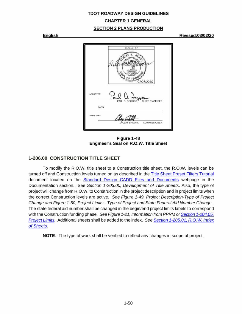
TDOT ROADWAY DESIGN GUIDELINES
CHAPTER 1 GENERAL
SECTION 2 PLANS PRODUCTION
English Revised:03/02/20
1-50
Figure 1-48 Engineer’s Seal on R.O.W. Title Sheet
1-206.00 CONSTRUCTION TITLE SHEET
To modify the R.O.W. title sheet to a Construction title sheet, the R.O.W. levels can be
turned off and Construction levels turned on as described in the Title Sheet Preset Filters Tutorial
document located on the Standard Design CADD Files and Documents webpage in the
Documentation section. See Section 1-203.00, Development of Title Sheets. Also, the type of
project will change from R.O.W. to Construction in the project description and in project limits when
the correct Construction levels are active. See Figure 1-49, Project Description-Type of Project
Change and Figure 1-50, Project Limits - Type of Project and State Federal Aid Number Change .
The state federal aid number shall be changed in the begin/end project limits labels to correspond
with the Construction funding phase. See Figure 1-21, Information from PPRM or Section 1-204.05,
Project Limits. Additional sheets shall be added to the index. See Section 1-205.01, R.O.W. Index
of Sheets.
NOTE: The type of work shall be verified to reflect any changes in scope of project.
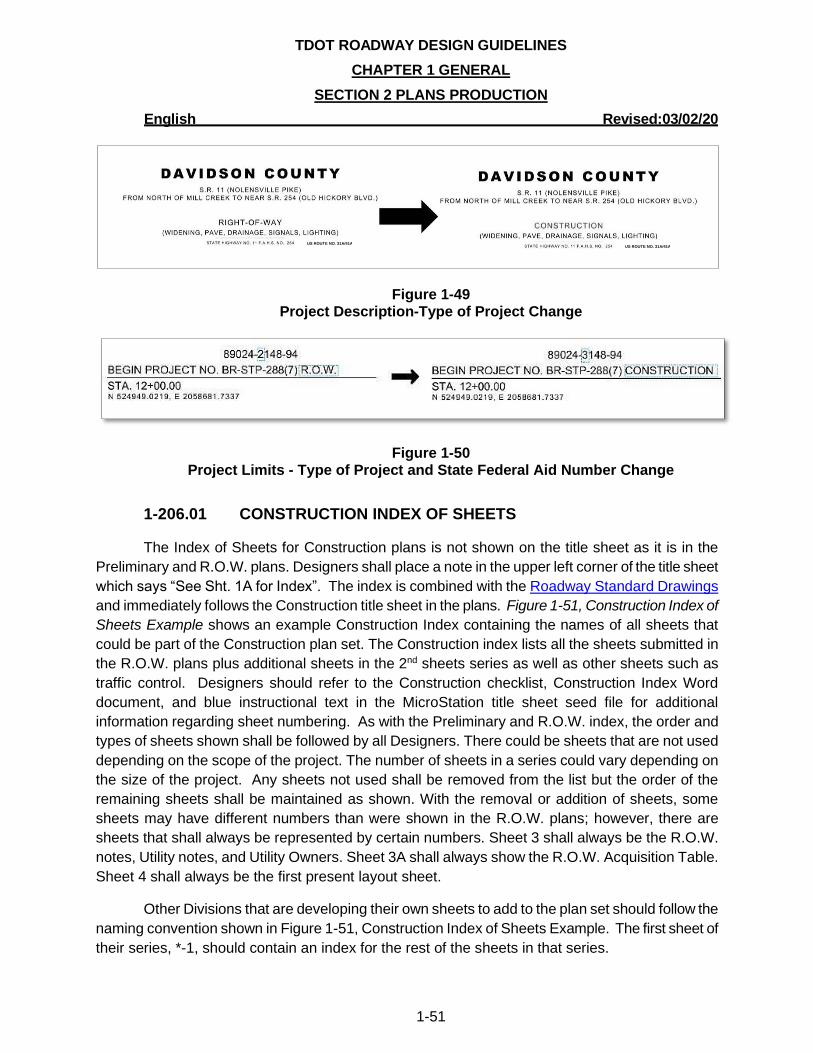
TDOT ROADWAY DESIGN GUIDELINES
CHAPTER 1 GENERAL
SECTION 2 PLANS PRODUCTION
English Revised:03/02/20
1-51
Figure 1-49 Project Description-Type of Project Change
Figure 1-50 Project Limits - Type of Project and State Federal Aid Number Change
1-206.01 CONSTRUCTION INDEX OF SHEETS
The Index of Sheets for Construction plans is not shown on the title sheet as it is in the
Preliminary and R.O.W. plans. Designers shall place a note in the upper left corner of the title sheet
which says “See Sht. 1A for Index”. The index is combined with the Roadway Standard Drawings
and immediately follows the Construction title sheet in the plans. Figure 1-51, Construction Index of
Sheets Example shows an example Construction Index containing the names of all sheets that
could be part of the Construction plan set. The Construction index lists all the sheets submitted in
the R.O.W. plans plus additional sheets in the 2nd sheets series as well as other sheets such as
traffic control. Designers should refer to the Construction checklist, Construction Index Word
document, and blue instructional text in the MicroStation title sheet seed file for additional
information regarding sheet numbering. As with the Preliminary and R.O.W. index, the order and
types of sheets shown shall be followed by all Designers. There could be sheets that are not used
depending on the scope of the project. The number of sheets in a series could vary depending on
the size of the project. Any sheets not used shall be removed from the list but the order of the
remaining sheets shall be maintained as shown. With the removal or addition of sheets, some
sheets may have different numbers than were shown in the R.O.W. plans; however, there are
sheets that shall always be represented by certain numbers. Sheet 3 shall always be the R.O.W.
notes, Utility notes, and Utility Owners. Sheet 3A shall always show the R.O.W. Acquisition Table.
Sheet 4 shall always be the first present layout sheet.
Other Divisions that are developing their own sheets to add to the plan set should follow the
naming convention shown in Figure 1-51, Construction Index of Sheets Example. The first sheet of
their series, *-1, should contain an index for the rest of the sheets in that series.
US ROUTE NO. 31A/41A US ROUTE NO. 31A/41A
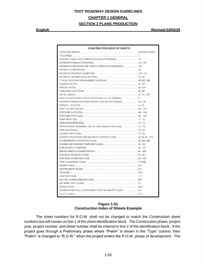
TDOT ROADWAY DESIGN GUIDELINES
CHAPTER 1 GENERAL
SECTION 2 PLANS PRODUCTION
English Revised:03/02/20
1-52
Figure 1-51 Construction Index of Sheets Example
The sheet numbers for R.O.W. shall not be changed to match the Construction sheet
numbers but will remain on line 1 of the sheet identification block. The Construction phase, project
year, project number, and sheet number shall be entered in line 2 of the identification block. If the
project goes through a Preliminary phase where “Prelim” is shown in the “Type” column, then
“Prelim” is changed to “R.O.W.” when the project enters the R.O.W. phase of development. The
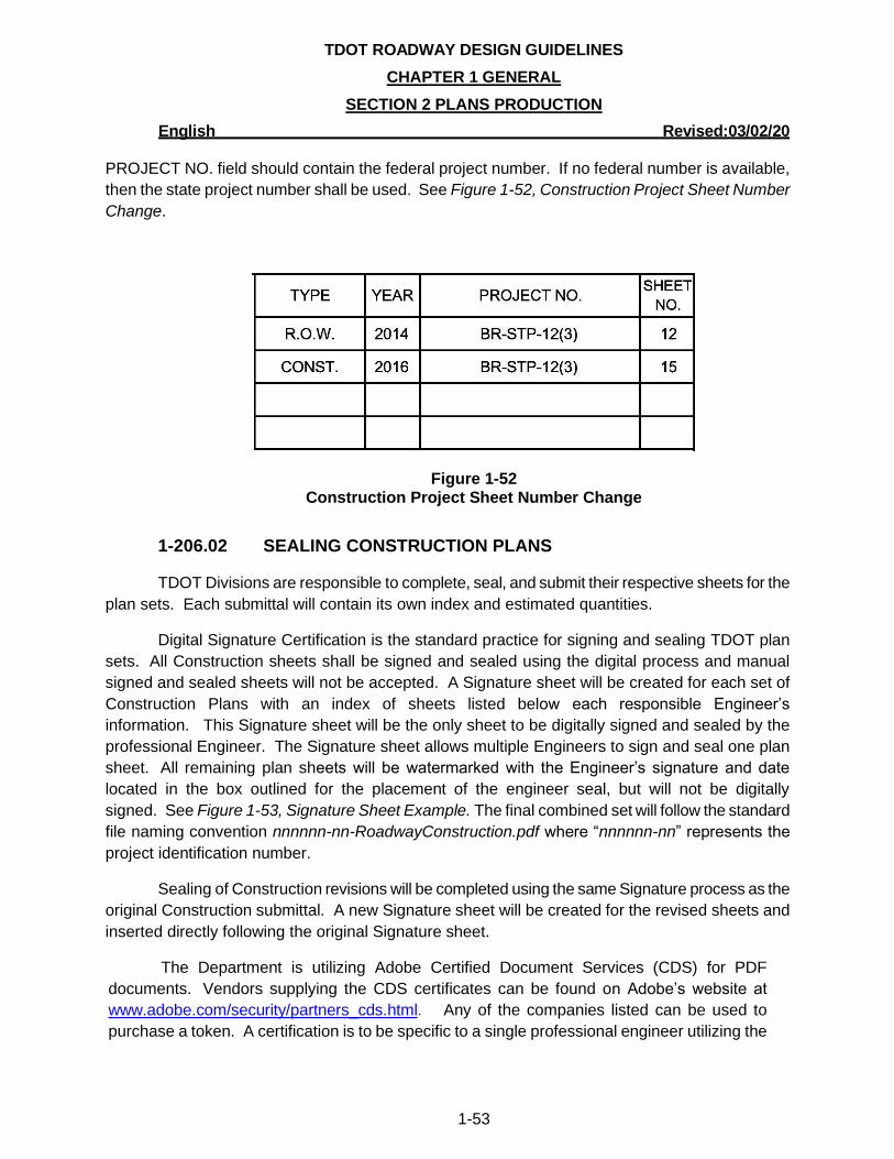
TDOT ROADWAY DESIGN GUIDELINES
CHAPTER 1 GENERAL
SECTION 2 PLANS PRODUCTION
English Revised:03/02/20
1-53
PROJECT NO. field should contain the federal project number. If no federal number is available,
then the state project number shall be used. See Figure 1-52, Construction Project Sheet Number
Change.
Figure 1-52 Construction Project Sheet Number Change
1-206.02 SEALING CONSTRUCTION PLANS
TDOT Divisions are responsible to complete, seal, and submit their respective sheets for the
plan sets. Each submittal will contain its own index and estimated quantities.
Digital Signature Certification is the standard practice for signing and sealing TDOT plan
sets. All Construction sheets shall be signed and sealed using the digital process and manual
signed and sealed sheets will not be accepted. A Signature sheet will be created for each set of
Construction Plans with an index of sheets listed below each responsible Engineer’s
information. This Signature sheet will be the only sheet to be digitally signed and sealed by the
professional Engineer. The Signature sheet allows multiple Engineers to sign and seal one plan
sheet. All remaining plan sheets will be watermarked with the Engineer’s signature and date
located in the box outlined for the placement of the engineer seal, but will not be digitally
signed. See Figure 1-53, Signature Sheet Example. The final combined set will follow the standard
file naming convention nnnnnn-nn-RoadwayConstruction.pdf where “nnnnnn-nn” represents the
project identification number.
Sealing of Construction revisions will be completed using the same Signature process as the
original Construction submittal. A new Signature sheet will be created for the revised sheets and
inserted directly following the original Signature sheet.
The Department is utilizing Adobe Certified Document Services (CDS) for PDF
documents. Vendors supplying the CDS certificates can be found on Adobe’s website at
www.adobe.com/security/partners_cds.html. Any of the companies listed can be used to
purchase a token. A certification is to be specific to a single professional engineer utilizing the
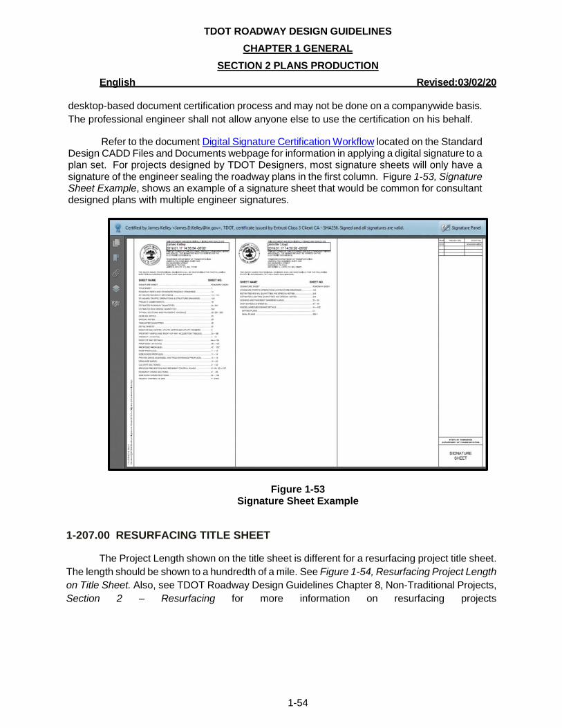
TDOT ROADWAY DESIGN GUIDELINES
CHAPTER 1 GENERAL
SECTION 2 PLANS PRODUCTION
English Revised:03/02/20
1-54
desktop-based document certification process and may not be done on a companywide basis.
The professional engineer shall not allow anyone else to use the certification on his behalf.
Refer to the document Digital Signature Certification Workflow located on the Standard Design CADD Files and Documents webpage for information in applying a digital signature to a plan set. For projects designed by TDOT Designers, most signature sheets will only have a signature of the engineer sealing the roadway plans in the first column. Figure 1-53, Signature Sheet Example, shows an example of a signature sheet that would be common for consultant designed plans with multiple engineer signatures.
Figure 1-53 Signature Sheet Example
1-207.00 RESURFACING TITLE SHEET
The Project Length shown on the title sheet is different for a resurfacing project title sheet.
The length should be shown to a hundredth of a mile. See Figure 1-54, Resurfacing Project Length
on Title Sheet. Also, see TDOT Roadway Design Guidelines Chapter 8, Non-Traditional Projects,
Section 2 – Resurfacing for more information on resurfacing projects
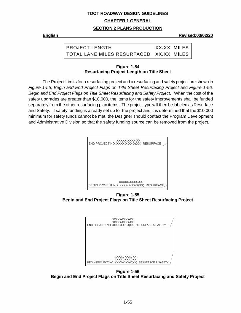
TDOT ROADWAY DESIGN GUIDELINES
CHAPTER 1 GENERAL
SECTION 2 PLANS PRODUCTION
English Revised:03/02/20
1-55
Figure 1-54 Resurfacing Project Length on Title Sheet
The Project Limits for a resurfacing project and a resurfacing and safety project are shown in
Figure 1-55, Begin and End Project Flags on Title Sheet Resurfacing Project and Figure 1-56,
Begin and End Project Flags on Title Sheet Resurfacing and Safety Project. When the cost of the
safety upgrades are greater than $10,000, the items for the safety improvements shall be funded
separately from the other resurfacing plan items. The project type will then be labeled as Resurface
and Safety. If safety funding is already set up for the project and it is determined that the $10,000
minimum for safety funds cannot be met, the Designer should contact the Program Development
and Administrative Division so that the safety funding source can be removed from the project.
Figure 1-55 Begin and End Project Flags on Title Sheet Resurfacing Project
Figure 1-56 Begin and End Project Flags on Title Sheet Resurfacing and Safety Project
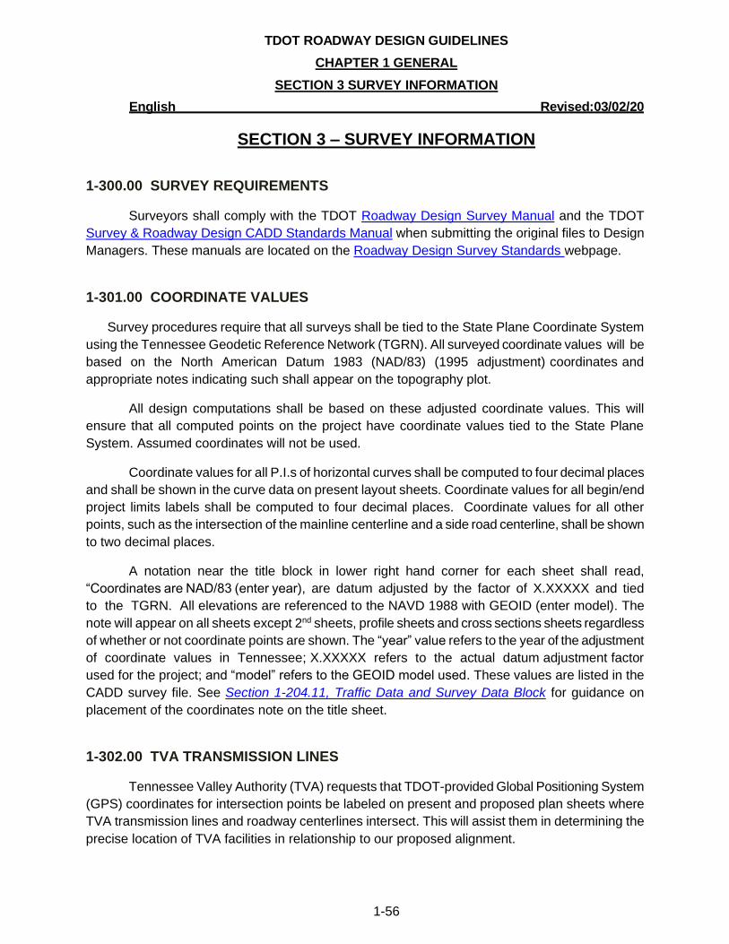
TDOT ROADWAY DESIGN GUIDELINES
CHAPTER 1 GENERAL
SECTION 3 SURVEY INFORMATION
English Revised:03/02/20
1-56
SECTION 3 – SURVEY INFORMATION
1-300.00 SURVEY REQUIREMENTS
Surveyors shall comply with the TDOT Roadway Design Survey Manual and the TDOT
Survey & Roadway Design CADD Standards Manual when submitting the original files to Design
Managers. These manuals are located on the Roadway Design Survey Standards webpage.
1-301.00 COORDINATE VALUES
Survey procedures require that all surveys shall be tied to the State Plane Coordinate System
using the Tennessee Geodetic Reference Network (TGRN). All surveyed coordinate values will be
based on the North American Datum 1983 (NAD/83) (1995 adjustment) coordinates and
appropriate notes indicating such shall appear on the topography plot.
All design computations shall be based on these adjusted coordinate values. This will
ensure that all computed points on the project have coordinate values tied to the State Plane
System. Assumed coordinates will not be used.
Coordinate values for all P.I.s of horizontal curves shall be computed to four decimal places
and shall be shown in the curve data on present layout sheets. Coordinate values for all begin/end
project limits labels shall be computed to four decimal places. Coordinate values for all other
points, such as the intersection of the mainline centerline and a side road centerline, shall be shown
to two decimal places.
A notation near the title block in lower right hand corner for each sheet shall read,
“Coordinates are NAD/83 (enter year), are datum adjusted by the factor of X.XXXXX and tied
to the TGRN. All elevations are referenced to the NAVD 1988 with GEOID (enter model). The
note will appear on all sheets except 2nd sheets, profile sheets and cross sections sheets regardless
of whether or not coordinate points are shown. The “year” value refers to the year of the adjustment
of coordinate values in Tennessee; X.XXXXX refers to the actual datum adjustment factor
used for the project; and “model” refers to the GEOID model used. These values are listed in the
CADD survey file. See Section 1-204.11, Traffic Data and Survey Data Block for guidance on
placement of the coordinates note on the title sheet.
1-302.00 TVA TRANSMISSION LINES
Tennessee Valley Authority (TVA) requests that TDOT-provided Global Positioning System
(GPS) coordinates for intersection points be labeled on present and proposed plan sheets where
TVA transmission lines and roadway centerlines intersect. This will assist them in determining the
precise location of TVA facilities in relationship to our proposed alignment.
TDOT ROADWAY DESIGN GUIDELINES
CHAPTER 1 GENERAL
SECTION 3 SURVEY INFORMATION
English Revised:03/02/20
1-57
1-303.00 DISTANCES, BEARINGS, AND CONTROL POINTS
In order to provide consistency and maintain accuracy, the following criteria are to be
adopted for all roadway plans:
• Distances shown on the plans shall be no more accurate than the nearest 0.01 foot (35 ft.,
35.0 ft., and 35.00 ft., are acceptable: 35.001 ft. is not acceptable), with the exception of the
begin/end project limits labels where 0.001 is acceptable.
• Bearings shown on the plans shall be no more accurate than 1 (one) second (for example N
35 00’ 01” E is acceptable; N 35 00’ 01.1” E is not acceptable).
• GPS control points shall be shown to an accuracy of 0.0001 foot.
1-304.00 TRACT NUMBERS ON PLANS
On all design projects, tract, and/or parcel numbers assigned during the survey process
shall not be deleted or altered unless directed by the HQ or Regional R.O.W. Office. Tract numbers
are assigned during the survey process and have the same parcel number in the GEOPAK “GPK”
file. The parcel information contained in the GPK file is used in survey and plan preparation and
R.O.W. processes. There shall not be any duplicate tract numbers on any one project.
No tract shall be deleted after the plans have been printed for a design public hearing.
For tracts where no acquisition is required, the Designer shall place a single line through all the
information for all such tracts in the R.O.W. Acquisition Table in the plans. The Designer shall also
place a line through all the no-acquisition tract numbers and owner names on the Property Maps
sheets, Present Layout sheets, R.O.W. Details sheets, and on any other plans sheets where these
tract numbers and owner names may appear. This will ensure that all tract information is retained in
the GPK file and not deleted nor altered. The tract information is then recoverable and can be used
by other sections as the information is passed to the R.O.W. and Operations Divisions or returned
to the Survey Office for updating.
1-305.00 UPDATING SURVEYS
It is the Designer’s responsibility to thoroughly review the survey information. Requests for
updates normally take place following the Preliminary Field Review and the Right-of-Way Field
Review, if necessary. Every effort shall be made to make sure all additional information required is
requested at these times which will reduce the number of times survey crews are sent out on the
same project.
After a request is made for Environmental Boundaries and wetlands are identified by the
Environmental Division or Environmental Tech Offices, the Designer or Design Manager shall
request additional survey information if the Environmental Boundary document does not provide
updated survey information obtained during the identification process.
TDOT ROADWAY DESIGN GUIDELINES
CHAPTER 1 GENERAL
SECTION 3 SURVEY INFORMATION
English Revised:03/02/20
1-58
Additional survey requests shall be made by email sent to the appropriate Regional Survey
office and shall be created using the template file Additional Survey Request Form.xltx located in
the DDOCS.zip file on the Standard Design and Survey CADD Files and Documents webpage.
When requesting additional information, requested information will be shown either in
electronic format or on a marked set of prints. Also, it may be necessary to include GEOPAK
information. This is covered in the CADD Standards document (CADDV8.pdf) located on the
Standard Design and Survey CADD Files and Documents webpage.
If a survey is updated, the updated survey date(s) shall be added to the title sheet of the
current phase of the project beside the traffic block as shown in Figure 1-37, Traffic Data and
Survey Data Block. .
TDOT ROADWAY DESIGN GUIDELINES
CHAPTER 1 GENERAL
SECTION 4 ESTIMATES
English Revised:03/02/20
1-59
SECTION 4 – ESTIMATES
1-400.00 ESTIMATED ROADWAY QUANTITIES
For each project, Designers shall create and maintain an estimate file of all roadway
quantities for project cost estimation. The project estimates may contain any combination of the
following types of quantities: roadway, bridge, box bridge, utility, R.O.W. relocation, signal, and/or
lighting. The estimated roadway quantity sheet included in the project plans may contain quantities
provided by other TDOT Divisions. An item number should only be used once per project. All
Divisions shall coordinate to determine if an item number is listed in multiple estimated quantity
files.
Estimates can be used to help predict costs of future projects of similar scope. The
estimated roadway quantities Excel file is part of various project deliverables, including finalized
Preliminary Plans, R.O.W. funding requests, Construction Field Reviews, and final Construction
plans distribution.
The Bid Analysis and Estimating Office provides a dollar figure to each listed item based on
historical data to determine a total cost that TDOT estimates it will need to complete the project.
The projected cost estimate is used by the Project Development and Administration Division for
budget updates throughout the life cycle of the project. The Program Development and
Administration Division authorizes funding for each stage of the project and compiles the list of
projects that are budgeted in the State Transportation Improvement Program (STIP). It is essential
that Designers create a complete, accurate and updated estimate when changes occur to ensure
that projected costs are within the funding allocated in the STIP.
Contractors also use the estimated roadway items to calculate a total dollar amount that it
would cost them to build the job and use this amount to bid on the project. TDOT’s and the
contractors’ estimates are compared during the Letting phase to ensure that the bids are not
obviously unbalanced, too high, or too low compared to TDOT’s cost estimate. Bid proposals may
be rejected by the Commissioner if they are excessive or below the reasonable cost analysis value.
Lump Sum (LS) quantities shall be 1 (one) unless the estimated roadway quantities file
includes multiple projects, and the same item number is in each project. Fractional Lump Sum (LS)
quantities for the same item number must add up to equal one or the program that the Estimating
Office uses will force it to one. Lump Sums for the same item number when multiple projects are in
the proposal shall not be rounded to 1 (one) each. Instead, the total quantity for a Lump Sum item
for all the projects in a single proposal shall total 1 (one). Lump Sums shall not add up to more than
1 (one) when the same item number is listed for multiple projects in the same estimated quantities
file. An example would be Traffic Control for two projects let together with each quantity equal to
0.5.

TDOT ROADWAY DESIGN GUIDELINES
CHAPTER 1 GENERAL
SECTION 4 ESTIMATES
English Revised:03/02/20
1-60
For item numbers with units of measure of EACH, the quantity shall not be a fraction. Some
quantities can be decimals such as pavement markings when unit of measure is L.M. (linear mile) if
the quantity is low, or between 1 and 5.5, since rounding up or down creates a percent change
greater than 10%. Square yards and tons shall always be whole numbers.
The quantity for all item numbers shall not be rounded if rounding (either up or down) results
in a change of 10% or more in the total quantity. For example, if 1.5 is rounded to 2.0, then the
change is 0.5/1.5 = 0.333 or 33.3%. If 1.75 is rounded to 2.0, then the percent change is 0.25/1.75
= 0.1428 or 14.3%. These examples shall not be rounded but shall remain 1.5 and 1.75,
respectively. However, if the quantity is calculated to be 1.85, then the percent change if rounding
up to 2.0 would be 0.15/1.85 = 0.081 or 8.1%. In this case, it is acceptable to round up to 2.0 (two)
for this item.
1-401.00 CREATING THE PRELIMINARY ROADWAY QUANTITIES ESTIMATE
The first estimate prepared by the Designer for a project is the preliminary estimate. This
estimate is a living document and shall be updated as the project develops.
Each estimate file contains quantities associated with each item of work that is needed to
build the project. Each item has an official item number, description, unit of cost, and associated
quantity. These items are listed in the items.dat file and only these approved items shall be used in
plans. The uses for many items in the items.dat file are described in detail in TDOT’s Standard
Specifications For Road and Bridge Construction, January 1, 2015 edition (See Part 1, Section 109,
Measurement and Payment, and all Sections in Part 2).
To download the complete list of approved roadway items in the items.dat file and/or to run a
quick search for an item either by item number or description keyword, go to the Roadway Item
Lists webpage.
If a new Roadway Design item number is needed, the Design Manager should contact the
HQ Roadway Design Division at [email protected]. If a new ITS item number is needed, the
Design Manager should contact the Traffic Operations Division at TDOT.TrafficOps.ITS-
[email protected]. If a new traffic signal of lighting item number is needed, the Design Manager
should contact the Traffic Operations Division at [email protected]. These
divisions will determine if an item number will be assigned or included in another item. If a new
item number is needed specific to a project, they will contact the HQ Construction Office to get the
new number.
The estimated roadway quantities sheet in project plans is created from an Excel file that
works in conjunction with the items.dat file. The template for the estimated roadway quantities
Excel file can be downloaded from the TDOT 2nd sheets.exe file located on the Standard Design
CADD Files and Documents webpage. See Figure 1-57, Estimated Quantities Project Data and
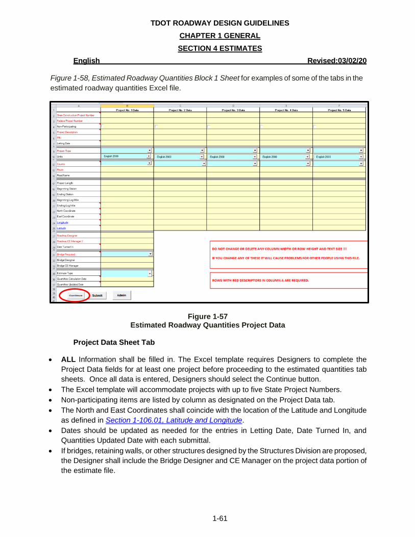
TDOT ROADWAY DESIGN GUIDELINES
CHAPTER 1 GENERAL
SECTION 4 ESTIMATES
English Revised:03/02/20
1-61
Figure 1-58, Estimated Roadway Quantities Block 1 Sheet for examples of some of the tabs in the
estimated roadway quantities Excel file.
Figure 1-57 Estimated Roadway Quantities Project Data
Project Data Sheet Tab
• ALL Information shall be filled in. The Excel template requires Designers to complete the
Project Data fields for at least one project before proceeding to the estimated quantities tab
sheets. Once all data is entered, Designers should select the Continue button.
• The Excel template will accommodate projects with up to five State Project Numbers.
• Non-participating items are listed by column as designated on the Project Data tab.
• The North and East Coordinates shall coincide with the location of the Latitude and Longitude
as defined in Section 1-106.01, Latitude and Longitude.
• Dates should be updated as needed for the entries in Letting Date, Date Turned In, and
Quantities Updated Date with each submittal.
• If bridges, retaining walls, or other structures designed by the Structures Division are proposed,
the Designer shall include the Bridge Designer and CE Manager on the project data portion of
the estimate file.
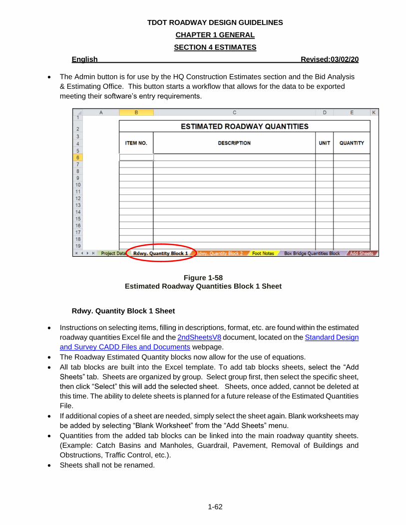
TDOT ROADWAY DESIGN GUIDELINES
CHAPTER 1 GENERAL
SECTION 4 ESTIMATES
English Revised:03/02/20
1-62
• The Admin button is for use by the HQ Construction Estimates section and the Bid Analysis
& Estimating Office. This button starts a workflow that allows for the data to be exported
meeting their software’s entry requirements.
Figure 1-58
Estimated Roadway Quantities Block 1 Sheet
Rdwy. Quantity Block 1 Sheet
• Instructions on selecting items, filling in descriptions, format, etc. are found within the estimated
roadway quantities Excel file and the 2ndSheetsV8 document, located on the Standard Design
and Survey CADD Files and Documents webpage.
• The Roadway Estimated Quantity blocks now allow for the use of equations.
• All tab blocks are built into the Excel template. To add tab blocks sheets, select the “Add
Sheets” tab. Sheets are organized by group. Select group first, then select the specific sheet,
then click “Select” this will add the selected sheet. Sheets, once added, cannot be deleted at
this time. The ability to delete sheets is planned for a future release of the Estimated Quantities
File.
• If additional copies of a sheet are needed, simply select the sheet again. Blank worksheets may
be added by selecting “Blank Worksheet” from the “Add Sheets” menu.
• Quantities from the added tab blocks can be linked into the main roadway quantity sheets.
(Example: Catch Basins and Manholes, Guardrail, Pavement, Removal of Buildings and
Obstructions, Traffic Control, etc.).
• Sheets shall not be renamed.
TDOT ROADWAY DESIGN GUIDELINES
CHAPTER 1 GENERAL
SECTION 4 ESTIMATES
English Revised:03/02/20
1-63
• If more than one PIN is associated with the project, the Designer should use the buttons to the
right to select the appropriate number of quantity columns (one per PIN). All items shall be
listed in numerical order. There is a ‘sort’ button to help with this task.
• Quantities cannot contain commas.
• Quantities shall be rounded up to the nearest whole number with the exceptions of those as
shown in Chapter 5 Item Numbers of the guidelines.
• Contractors are paid by the quantities that are ordered and used on the project. If there is an
item number in question that may not be used on the project, it shall be added to the estimate. It
is better to have it shown on the estimate and not used by the contractor than needed after
Letting as a change order. These items shall be discussed at the Construction Field Review and
footnoted “Requested by _______Division.”
• Projected quantities for erosion control and traffic control shall be included in the preliminary
estimate even though traffic control sheets are not included in the preliminary or R.O.W. plans.
Quantities from similar projects can be used to help estimate these quantities.
• If open-ended and/or lump sum item numbers are used, the Designer shall fill in the
descriptions in the estimate data file. Without completing these item descriptions, there is no
way the estimator in the Bid Analysis & Estimating Office can complete the preliminary
construction cost estimate.
• Box-Bridge items shall be listed on a sheet separate from the roadway items. Use the sheet
labeled Box Bridge Quantities sheet.
• Alternate roadway items shall be listed after all of the other roadway items. The alternates will
be designated in column C as Alternate AA1, Alternate AA2, Alternate AA3, Alternate AB1,
Alternate AB2, and so on. AA1 would alternate with AA2 and AA3. AB1 would alternate with
AB2, etc.
• No prices shall be entered in the estimate.
1-402.00 SUBMITTAL OF ESTIMATES
As previously noted in Section 1-400.00, Estimated Roadway Quantities, the Program
Development and Administration Division authorizes funding for each stage of the project and
compiles the list of projects that are budgeted in the STIP. It is essential that Designers create a
complete and accurate estimate and update and re-submit the estimate when changes occur to
ensure that projected costs are within the funding allocated within the STIP. The following sections
will explain how often an estimate should be updated and submitted for use in budgeting.
1-402.01 SUBMITTAL OF THE PRELIMINARY ESTIMATE
For PPRM Activity #390 Finalize Preliminary Plans, the Design Manager responsible for the project shall place the Excel quantity file nnnnnn-nn-PreliminaryEstimate.xlsm on FileNet and send an email notification to the appropriate Strategic Transportation Investments Division (STID) regional email [email protected], [email protected], [email protected], or
TDOT ROADWAY DESIGN GUIDELINES
CHAPTER 1 GENERAL
SECTION 4 ESTIMATES
English Revised:03/02/20
1-64
[email protected], and carbon copy (Cc) the Program Development and Scheduling Office at [email protected]. The estimate shall be submitted after the Preliminary Field Review is held and the estimate is updated accordingly.
The subject line shall read:
Region X, County Name, Project Description (as shown in PPRM), Federal Project
Number, State Project Number, PIN nnnnnn-nn, Preliminary Estimate Submittal
Each Designer shall ensure the following is addressed in the preliminary estimate:
• If bridges, retaining walls, or other structures designed by the Structures Division are
proposed, the Designer shall indicate structures are required within the body of the email.
This information is necessary to ensure that the structures are included in the preliminary
estimate.
• The Designer shall send the preliminary construction Excel quantities estimate data via
email to the Design Manager responsible for the project. Design Managers and Designers
shall keep a copy of the estimate file in the project folder and keep the email message that
shows the date the estimate was emailed.
If an estimate is submitted during the preliminary stage, for plans associated with a public
hearing, or from a request by the Program Development and Administrative Division, an updated
estimate shall be submitted if a time lapse of one year has occurred since the previous estimate
was submitted. If there is a time lapse of over one year between the preliminary project submittal
and the projected request date for R.O.W. funding, an updated preliminary estimate shall be
completed and placed on FileNet with the name nnnnnn-nn-PreliminaryEstimate.xlsm. The name
shall not include a revision date for the file placed on FileNet. The original estimate placed on
FileNet shall be removed. The Design Manager shall email the appropriate Strategic Transportation
Investments Division (STID) regional email [email protected], [email protected],
[email protected], or [email protected], and carbon copy (Cc) [email protected].
If there are items that will be used on the project but the quantities are unknown, this shall be
mentioned in the body of the email. The email shall also state that the estimate is being submitted
because it has been a year since the last submittal. If there are NO CHANGES in the estimate
from the previous submittal, it shall be stated in the body of the email that there are NO
CHANGES from the previous estimate that was submitted on DD/MM/YYYY but shall still be
placed on FileNet and the other removed. All updated estimates shall be kept in the project folder.
For the project folder, a date shall be part of the naming convention so that the development of the
estimate can be easily compared.
TDOT ROADWAY DESIGN GUIDELINES
CHAPTER 1 GENERAL
SECTION 4 ESTIMATES
English Revised:03/02/20
1-65
1-402.02 SUBMITTAL OF R.O.W. ESTIMATE FOR R.O.W. OR UTILITIES ONLY FUNDING
As plans develop into the R.O.W. phase, additional items shall be added to the preliminary
estimate and renamed the Roadway R.O.W. estimate (nnnnnn-nn-RoadwayROWEstimate.xlsm).
This is a replacement for what was originally called the preliminary estimate. This is not a
substitution for the Form 44 ROW estimate which will continue to be submitted by the R.O.W.
personnel. PPRM Activity #585 Finalize R.O.W. Plans shall include updating the estimate from
comments received at the Site Review and R.O.W. Field Review. The R.O.W. estimate shall be
part of the request for R.O.W. or Utilities Only funding. If there are retaining walls on the project,
please refer to Chapter 2 Section 2-304.02 Retaining Walls Pay Item for guidance on including
retaining wall quantities in the R.O.W. estimate for R.O.W. plans.
After R.O.W. submittal, if there is a time lapse of over one year between R.O.W. submittal
and the distribution of the Construction Field Review notice, an updated R.O.W. estimate shall be
completed and placed on FileNet with the name nnnnnn-nn-RoadwayROWEstimate.xlsm. The
name shall not include a revision date for the file placed on FileNet. The previous estimate placed
on FileNet shall be removed. The Design Manager shall email
[email protected] with a carbon copy (Cc) to [email protected] that
nnnnnn-nn-RoadwayROWEstimate.xlsm was placed on FileNet. The email shall state that the
estimate is being submitted because it has been a year since the last submittal. If there are NO
CHANGES in the estimate from the previous submittal, it shall be stated in the email that
there are NO CHANGES from the previous estimate that was submitted on DD/MM/YYYY, but
shall still be placed on FileNet and the other removed. All updated estimates shall be kept in the
project folder. For the project folder, a date shall be part of the naming convention so that the
development of the estimate can be easily compared.
If there are significant changes, additions, or revisions to the R.O.W. plans that affect the
estimate, a revised estimate shall be completed and placed on FileNet with the name nnnnnn-nn-
RoadwayROWEstimate.xlsm. The name shall not include a revision date for the file placed on
FileNet. The previous estimate placed on FileNet shall be removed. The Design Manager shall
email [email protected] with a carbon copy (Cc) to [email protected]. The
email shall state that the estimate is being submitted because of significant changes, additions, or
revisions to the R.O.W. plans. All updated estimates shall be kept in the project folder. For the
project folder, a date shall be part of the naming convention so that the development of the estimate
can be easily compared.
1-402.03 RESUBMITTALS OF ESTIMATES DUE TO AN INSTRUCTIONAL BULLETIN OR ROADWAY DESIGN GUIDELINES CHANGE
As stated in previous sections, the Designer shall update the estimate and submit yearly
and/or when significant changes have occurred. For projects that are not funded for construction but
TDOT ROADWAY DESIGN GUIDELINES
CHAPTER 1 GENERAL
SECTION 4 ESTIMATES
English Revised:03/02/20
1-66
have been submitted for R.O.W., the Designer shall take time to update the estimate according to
changes in Instructional Bulletins/ Design Guidelines. For the same situation, the Consultant is
allowed one week per calendar year to review the Instructional Bulletins/ Design Guidelines, and
update any estimates that correspond to those changes.
1-402.04 SUBMITTAL OF CONSTRUCTION ESTIMATE FOR CONSTRUCTION FIELD REVIEW
When plans are developed and ready for Construction Field Review distribution, the
estimate shall be complete with any previous missing items and descriptions filled in. If a
Constructability Review was held, all changes to the quantities as a result of the review shall be
reflected in the Roadway Construction Field Review quantity estimate. The Design Manager shall
request necessary information needed to complete the estimate sheet at least two weeks
prior to the date set to print for outside distribution. Requests for large projects should be
made even earlier to ensure that the estimate is complete and that sheets from the estimates are
correct in the Construction Field Review plan set. Plans sheets and items shall be requested from
Geotechnical, Traffic Operations, Structures, and Utilities personnel as needed. All Divisions
submitting estimates shall coordinate with other Divisions to verify no duplicate item numbers are
submitted.
The Design Manager shall email the Construction Field Review quantity estimate nnnnnn-
nn-RoadwayConstructionFieldReviewEstimate.xlsm to [email protected] with
a carbon copy (Cc) to [email protected] on the same day the Construction Field Review Notice
is sent out which occurs approximately 7 months prior to submittal of final construction plans for
Letting. If the project has utilities that will be part of the plans, the request should be made to Utility
staff to provide the utility Excel estimate. If the project has structures and/or retaining walls, the
Excel file for those quantities shall be obtained and emailed simultaneously with the estimated
roadway quantities Excel estimate. The name of the structures estimate shall be nnnnnn-nn-
StructuresConstructionFieldReviewEstimate.xlsm. (See below for further instruction)
The email subject line shall read:
Region X, County Name, Project Description (as shown in PPRM), Federal Project
Number (if applicable), State Project Number, PIN nnnnnn-nn, Construction Field Review
Estimate Submittal
The following must be completed BEFORE the estimate is emailed with the Construction
Field Review Notice:
• The Designer shall ensure that the totals on the estimate reflect all tabulation blocks
shown in the plans.

TDOT ROADWAY DESIGN GUIDELINES
CHAPTER 1 GENERAL
SECTION 4 ESTIMATES
English Revised:03/02/20
1-67
• If there are Traffic Operations quantities (ITS, Signals, and/or Lighting), the Design
Manager over the project shall request the appropriate Excel files containing these
quantities:
o nnnnn-nn-TrafficOpsITSConstructionFieldReviewEstimate.xlsm
o nnnnnn-nnTrafficOpsSignalsConstructionFieldReviewEstimate.xlsm
o nnnnnn-nn-TrafficOpsLightingFieldReviewEstimate.xlsm
These items will NOT be added to the estimated roadway quantities Excel file but
will be included as a separate file within the same email.
• If there are structures (bridges) in the plans, the Design Manager over the project
shall contact TDOT Structures Division personnel to request the Excel file nnnnnn-
nn-StructuresConstructionFieldReviewEstimate.xlsm containing these
quantities. These items will NOT be added to the estimated roadway quantities
Excel file but will be included as a separate file within the same email.
• If there are retaining walls in the plans, the Design Manager over the project shall
contact Structures ([email protected]) to request the Excel file:
nnnnnn-nn-StructuresConstructionFieldReviewEstimate.xlsm. If there are both
structures and retaining walls, coordination shall occur between Structures
personnel to combine these quantities into one file and to submit the file to the
Design Manager that requested the information. These items will NOT be added to
the estimated roadway quantities Excel file, but will be included as a separate file
within the same email as an attachment.
• If utilities are being moved as part of the state contract (Chapter 86), the Design
Manager over the project shall contact the regional utility office and request the
Excel file for the utility items. The utility items will be added as a tab in the estimated
roadway quantities Excel file and shall be shown on the Estimated Utilities
Quantities and Special Notes sheet of the plans. The Designer shall create the
Estimated Utilities Quantities and Special Notes sheet. The sheet will not be
supplied by the utility office.
• The Design Manager shall contact the R.O.W. office to check to see if there will be
R.O.W. Removal Items for buildings and obstructions. The item numbers shall be
furnished by the regional R.O.W. office and should be a lump sum item and
footnoted. See Section 5-202.02, Removal of Buildings and Obstructions for
additional information.
The estimate shall be thoroughly checked at the Construction Field Review to ensure that
there are no missing quantities or adjustments that must be made to existing quantities. Close
attention should be paid to the grade differences and the construction of structures to ensure if
items are needed for temporary shoring. If there are significant changes and additions to quantity
items due to comments at the Construction Field Review, a revised estimate for the applicable
division shall be completed (named nnnnnn-nn-RoadwayConstructionFieldReview Estimate.xlsm,
nnnnnn-nn-TrafficOpsITSConstructionFieldReviewEstimate.xlsm, nnnnnn-nn-TrafficOpsSignals
ConstructionFieldReviewEstimate.xlsm, nnnnnn-nn-TrafficOpsLightingConstructionFieldReview
TDOT ROADWAY DESIGN GUIDELINES
CHAPTER 1 GENERAL
SECTION 4 ESTIMATES
English Revised:03/02/20
1-68
Estimate.xlsm or nnnnnn-nn-StructuresConstructionFieldReviewEstimate.xlsm) and emailed by the
Design Manager to [email protected] with a carbon copy (Cc) to
[email protected]. The email shall state that the estimate(s) is being re-submitted because
of significant changes and/or additions resulting from the Construction Field Review. All
updated estimates shall be kept in the project folder. For the project folder, a date shall be part of
the naming convention so that the development of the estimate can be easily compared. It is not
necessary to place the estimate on FileNet.
1-402.05 SUBMITTAL OF CONSTRUCTION ESTIMATE FOR LETTING PROCESS
When the final construction plans are turned in for the Letting process for PPRM Activity #
715 Finalize Roadway Construction Plans, the submittal will include a final construction estimate.
The Designer or Design Manager shall attach the construction Excel estimate nnnnnn-nn-
RoadwayConstructionEstimate.xlsm to the email containing the Construction Submittal for Letting.
The Designer or Design Manager will upload the Excel estimate file to FileNet. The previous
estimate placed on FileNet shall be removed. The Designer or Design Manager shall email the
Construction Submittal Letter, Grading Quantities, and Construction Estimate to the addresses
shown in Table 1-12 for the internal email distribution list. The body of the email shall include that
the construction plan set and estimated roadway quantities Excel file have been uploaded to
FileNet.
The subject line shall read:
Region X, County Name, Project Description (as shown in PPRM), Federal Project
Number, State Project Number, PIN nnnnnn-nn, Roadway Construction Plans and Estimate
Submittal for DD/MM/YYYY Letting
A copy of the email shall be placed in the project folder to document the submittal of the
construction estimate.
If there are Traffic Operations sheets and quantities (ITS, signals, and/or lighting) in the
plans, the Traffic Operations Division shall upload the Excel the Excel quantity file nnnnnn-nn-
TrafficOpsITSConstructionEstimate.xlsm, nnnnnn-nn-TrafficOpsSignalsConstructionEstimate.xlsm,
and/or nnnnnn-nn-TrafficOpsLightingConstructionEstimate.xlsm to FileNet. The Traffic Operations
Division emails the Construction Submittal Letter and Construction Estimate to the addresses
shown in Table 1-12 for the internal distribution list. The body of the email shall include that the
Traffic Operations construction plan set and estimated Traffic Operations quantities Excel file have
been uploaded to FileNet.
Note: These items will NOT be added to the estimated Roadway quantity Excel file but will
be emailed as a separate file. Traffic Operations shall coordinate with all Divisions to verify no
duplicate item numbers are submitted.
TDOT ROADWAY DESIGN GUIDELINES
CHAPTER 1 GENERAL
SECTION 4 ESTIMATES
English Revised:03/02/20
1-69
The subject line shall read:
Region X, County Name, Project Description (as shown in PPRM), Federal Project
Number, State Project Number, PIN nnnnnn-nn, Traffic Operations Construction Plans and
Estimate Submittal for DD/MM/YYYY Letting
If there are structure sheets and quantities (bridges or retaining walls) in the plans, the
Structures Division shall upload the Excel quantity file, nnnnnn-nn-StructuresConstruction
Estimate.xlsm and structures construction plans to FileNet. The Structures Division emails the
Construction Submittal Letter and Construction Estimate to the addresses shown in Table 1-12 for
the internal email distribution list. The body of the email shall include that the structures
construction plan set and estimated structure quantities Excel file have been uploaded to FileNet.
Note: Structures shall coordinate with all Divisions to verify no duplicate item numbers are
submitted.
The subject line shall read:
Region X, County Name, Project Description (as shown in PPRM), Federal Project
Number, State Project Number, PIN nnnnnn-nn, Structures Construction Plans and Estimate
Submittal for DD/MM/YYYY Letting
1-402.06 REVISION OF CONSTRUCTION ESTIMATE FOR LETTING PROCESS
If there is a need to change, add, and/or delete quantities after Final Turn-in for the Letting
process but prior to the Letting of the project, a revision shall be made to the construction Excel
estimate by the appropriate Division. The revised file name shall be nnnnnn-nn-
RoadwayConstructionEstimate-Rev-mm-dd-yy.xlsm, nnnnnn-nn-StructuresConstructionEstimate-Rev-
mm-dd-yy.xlsm, nnnnnn-nn-TrafficOpsITSConstructionEstimate-Rev-mm-dd-yy.xlsm, nnnnnn-nn-
TrafficOpsSignalsConstructionEstimate-Rev-mm-dd-yy.xlsm and / or nnnnnn-nn-TrafficOpsLighting
ConstructionEstimate-Rev-mm-dd-yy.xlsm. It shall become part of the project record and placed in
the project folder but does not have to be distributed or uploaded to FileNet.
The Designer shall also create an estimate revision request using the Excel template file
Estimate Revision Request.xltx located in C:\Users\Public\Office Standards\TDOT Letters. The
contents of the TDOT Letters folder may be downloaded by running the DDocs.exe file located in
the Office section of the Standard Design CADD Files and Documents page. See Figure 1-59,
Estimate Revision Request for an example Estimate Revision Request. In the construction plan
set, each revised quantity shall be shown on the estimated roadway quantities sheet tabulation
block, included in the revision note on affected sheets, and reflected in any associated tabulation
blocks and/or footnotes. The Design Manager shall email the “Estimate Revision Request” form
and revised plan sheets as an attachment to the addresses shown in Table 1-12, Internal Email
Distribution List.
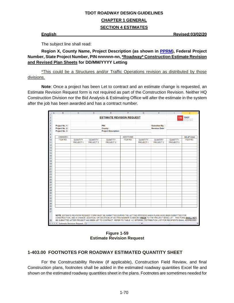
TDOT ROADWAY DESIGN GUIDELINES
CHAPTER 1 GENERAL
SECTION 4 ESTIMATES
English Revised:03/02/20
1-70
The subject line shall read:
Region X, County Name, Project Description (as shown in PPRM), Federal Project
Number, State Project Number, PIN nnnnnn-nn, *Roadway* Construction Estimate Revision
and Revised Plan Sheets for DD/MM/YYYY Letting
*This could be a Structures and/or Traffic Operations revision as distributed by those
divisions.
Note: Once a project has been Let to contract and an estimate change is requested, an
Estimate Revision Request form is not required as part of the Construction Revision. Neither HQ
Construction Division nor the Bid Analysis & Estimating Office will alter the estimate in the system
after the job has been awarded and has a contract number.
Figure 1-59 Estimate Revision Request
1-403.00 FOOTNOTES FOR ROADWAY ESTIMATED QUANTITY SHEET
For the Constructability Review (if applicable), Construction Field Review, and final
Construction plans, footnotes shall be added in the estimated roadway quantities Excel file and
shown on the estimated roadway quantities sheet in the plans. Footnotes are sometimes needed for
TDOT ROADWAY DESIGN GUIDELINES
CHAPTER 1 GENERAL
SECTION 4 ESTIMATES
English Revised:03/02/20
1-71
items to provide clarity, to define when substitutions can be made, and to define maintenance
schedules or cycles. Footnotes for quantities should be in numerical order and placed in column A.
Additional information for required footnotes can be found in the Roadway Design Guidelines
Chapter 5.
1. When an item is used in multiple locations for various reasons, footnotes shall be used to
define what the use and quantity is for each item within the total. For example, Item No.
303-10.01, Mineral Aggregate (Size 57) with a total of 181 TONS may have the following
footnote:
INCLUDES 5 TONS FOR USE WITH SEDIMENT FILTER BAG, 9 TONS FOR
CULVERT PROTECTION TYPE 1, AND 167 TONS FOR HAUL ROADS.
2. Where lump sum (LS) quantities are used, the description shall be filled in and a breakdown
of the items included in the lump sum shall be footnoted. For example, Item No. 730-40.02,
Temporary Traffic Signal System, LS, with a quantity of 1 may have a footnote similar to the
following:
INCLUDES ALL ITEMS NECESSARY TO KEEP EXISTING SIGNAL AT SR 248 AND I-65
SB OFF RAMP OPERATIONAL DURING ALL PHASES OF CONSTRUCTION.
CONTRACTOR TO COORDINATE WITH CITY ENGINEER PRIOR TO ANY
ADJUSTMENTS. CONTRACTOR SHALL OBTAIN THE APPROVAL FROM CITY ON
MANNER OF MAINTAINING EQUIPMENT THROUGH CONSTRUCTION PHASING.
VEHICLE DETECTION MUST BE MAINTAINED THROUGHOUT CONSTRUCTION
(VIDEO OR OTHER MEANS ACCEPTABLE). MAY USE CONTRACTOR OWNED
EQUIPMENT TO SUPPLEMENT EXISTING EQUIPMENT IF NEEDED. CONTRACTOR
SHALL MAINTAIN ALL EQUIPMENT DURING CONSTRUCTION, THROUGH A MINIMUM
OF 2 PHASES OF CONSTRUCTION. ITEM INCLUDES MAINTENANCE OF EXISTING
POLES OR PROVIDING ALTERNATE TEMPORARY SIGNAL SUPPORT POLES. SEE
TDOT STANDARD DRAWING T-SG-11 FOR ADDITIONAL DETAILS.
3. For items such as erosion control that might have to be replaced during the life cycle of the
project, the following footnote below shall be used:
SEE SUBSECTION 209.07 OF THE STANDARD SPECIFICATIONS FOR MAINTENANCE
REPLACEMENT.
1-404.00 ESTIMATE CONFIDENTIALITY
The Designer is hereby instructed to follow the TDOT guidelines regarding the handling of
the construction cost estimates and unit bid prices as listed below.
TDOT ROADWAY DESIGN GUIDELINES
CHAPTER 1 GENERAL
SECTION 4 ESTIMATES
English Revised:03/02/20
1-72
1. Construction Cost Estimates: All Designers are hereby instructed to keep the
construction cost estimate confidential. These cost estimates shall never be made public
and may only be revealed to the proper officials of TDOT. Should an inquiry be made by
a person other than a TDOT official, refer the inquirer to a Design Manager. Secure the
cost estimates at all times so that no unauthorized person may have access to them.
2. Unit Bid Prices: After a project is let for construction, but prior to awarding it, all
Designers are hereby instructed not to divulge any unit prices bid on a project to
anyone. When a project bid is rejected and not awarded, the unit prices are never to be
made public. Any inquiry made in regard to bid prices shall be referred to your Design
Manager for proper handling.
1-405.00 FINANCIAL PLANS
Federal law requires a financial plan to be completed for projects estimated to cost over $100
million. If a project exceeds $500 million, then the financial plan shall be submitted to Federal
Highway Administration for review. Once the Environmental Document is completed and the $100
million cost threshold is met, the TDOT Federal Affairs Liaison will develop the initial document
template. The financial plan must be updated annually by the Project Development Director. If it is
determined later in the design development process that the cost estimate will exceed $100 million,
the Project Development Director should contact the TDOT Federal Affairs Liaison and the
Community Relations Office. The TDOT Federal Affairs Liaison will provide the Project
Development Director with the project specific financial plan template. An example of a completed
document can be found on the Design Guidelines page.
.
TDOT ROADWAY DESIGN GUIDELINES
CHAPTER 1 GENERAL
SECTION 5 FIELD REVIEWS
English Revised:03/02/20
1-73
SECTION 5 – FIELD REVIEWS
1-500.00 TYPES OF FIELD REVIEWS
The Designer and Design Manager shall consult the Roadway Design Checklists for each
stage of deliverables to ensure all necessary items from the checklists are complete and ensure all
preceding PPRM activities are completed prior to scheduling the review. See Section 1-201.00,
Roadway Design Checklists. There is no standard for conducting field reviews. However, it is
suggested that the manager conducting the review, discuss utility and other external parties
concerns first. Emphasis shall always be placed on the construction staging of the project to ensure
sufficient ROW is acquired, detours and/or haul roads are in place if needed, and estimated
quantities identified. It is essential that early environmental concerns be discussed that could delay
the project or change the time of the year that the project can be constructed. It is not necessary to
go page by page for formatting and repetitive issues that can be marked up and given to the Design
Manager.
Preliminary Field Review (PPRM Activity #375): The project shall be approximately 30%
complete. The horizontal and vertical alignment shall be set and all items complete as listed in the
Preliminary Checklist. A preliminary estimate shall be submitted. See Section 1-402.01, Submittal
of the Preliminary Estimate, for additional information. A site visit by the Design Team is required
prior to this field review.
For small scope projects (bridge and approach, SIA, etc.), an official Preliminary Field
Review does not have to be held. Plans shall be placed on FileNet. Email notification with Field
Review Letter shall be sent to appropriate personnel listed on the internal distribution list with
reference to plans placed on FileNet. The Field Review Letter and plans shall be sent to
appropriate persons listed on external distribution list. A request for comments with deadline
shall be part of the letter since an official field review does not have to be held.
For large scope projects, an official Preliminary Field Review shall be held. Plans shall
be placed on FileNet. Email notification with Field Review Letter shall be sent to appropriate
personnel listed on the internal distribution list with reference to plans placed on FileNet. The
Field Review Letter and plans shall be sent to appropriate persons listed on external distribution
list. The Field Review letter shall list time and location of review and request for comments with
deadline for those unable to attend in person.
Site Review (PPRM Activity #531): The project shall be approximately 40% complete and
include all changes identified at the Preliminary Field Review and any changes necessary due to
feedback from the Initial Studies Request. All proposed retaining walls shall be identified and shown
on the plans. The plans shall include preliminary bridge layouts containing the plans and profile of
the proposed structures, typical sections with construction phasing, and other pertinent data. The
TDOT ROADWAY DESIGN GUIDELINES
CHAPTER 1 GENERAL
SECTION 5 FIELD REVIEWS
English Revised:03/02/20
1-74
Site Review document shall be filled out by the Designer with as much information as possible and
ensure each retaining wall has its own sheets associated with it. The Design Manager overseeing
the project should check the document prior to distribution. The document should be distributed to
personnel as defined in the site review document in concurrence with the Site Review notice. This
is an internal review and is not intended for local governments or utility companies. Invitees should
review the information that is already filled out and see if there is additional information that can be
sent back to the Designer. This review must be held on the project location. Although Google Earth
or other similar tools can allow the user to view the project site, vital information such as eroded
areas, traffic issues, site distance issues both longitudinally and at intersections, evidence of
geometric identifiers at intersections that suggest the turning radii needs improvement, evidence of
debris, and velocity or bank erosion at culverts, etc. can only be seen at the project site. The project
site will be analyzed by all of the attendees to determine if the best design is proposed. All proposed
retaining walls will be addressed during the review to determine which walls will be designed by the
Structures Division and submitted in the R.O.W. plans. It will also be determined at this Site Review
if a Constructability Review shall be held by the Headquarters Construction Division.
Right-of-Way Field Review (PPRM Activity #540): The project shall be approximately 80%
complete. All aspects of the roadway design needed for R.O.W. identification and purchase and
utility relocation shall be complete. All comments from the Preliminary Field Review and Site
Review should be incorporated into the plans and the estimate. The plans shall include all items
listed in the checklist including preliminary bridge layouts containing the plans and profile of the
proposed structures, typical sections with construction phasing, and other pertinent data. The
Estimated Roadway Quantity Sheet and Traffic Control Sheets shall be a draft version and printed
for informational purposes only for the R.O.W. Field Review. The sheets will be independent pdf
files uploaded in the R.O.W. submittal package. The sheets will not be shown in the R.O.W Index
and shall not be part of the final R.O.W. submittal. The sheet(s) shall have the Info Only stamp. The
quantities shown on the estimated roadway quantity sheet shall be discussed to ensure that all
aspects of the plans are discussed during the R.O.W. phase, specifically traffic control and
construction phasing. After the field review, changes shall be made to the traffic control sheets prior
to R.O.W. submittal. When R.O.W. plans are submitted, the draft traffic control plans will be an
independent pdf named nnnnnn-nn-DraftTrafficControlROW.pdf and placed on FileNet. After
submittal, these plans will not be updated. The estimate will not be added to FileNet, but the
estimate file should be updated based on comments received at the field review. An additional site
visit is only required if deemed necessary by the Design Team.
Constructability Review (PPRM Activity #690): The project shall be approximately 100%
complete and follow the deliverable as shown in the Construction Field Review. This review should
occur at least two months prior to the Construction Field Review. This review is initiated by the
Design Team or HQ Construction Division. This review will provide a forum for the construction
industry to share their knowledge and experience on construction and sequencing, traffic control,
utility conflicts, utility schedule, and alternate construction methods by utilizing their expertise to
ensure that difficult projects are buildable, cost-effective, and biddable. This review is not
TDOT ROADWAY DESIGN GUIDELINES
CHAPTER 1 GENERAL
SECTION 5 FIELD REVIEWS
English Revised:03/02/20
1-75
mandatory, and the need for this review shall be determined at the Site Review. This review will be
held by the Headquarters Construction Division, Regional Operations, and Design Team.
Please refer to the Constructability Review Procedures Manual for information on
managerial and team roles, participant selection, schedule, and record keeping. The manual can be
found on the Constructability Reviews website.
Construction Field Review (PPRM Activity #695): The project shall be approximately
100% complete and shall occur approximately six (6) months prior to Letting if possible. For
accelerated and/or small projects, the schedule may not allow time for 6 months pre turn-in window.
If a Constructability Review (PPRM Activity #690) was held, all changes shall be incorporated into
the plans and the field review notice shall include the Constructability Review meeting notes. All
sections of the roadway plans, structures plans (including bridges and retaining wall plans designed
by the Structures Division), and utility rainbow plans (utility relocations plans) as well as estimated
utility quantity sheets for utilities that are part of the state contract shall be included in the field
review plans. Estimates shall be sent out with the field review notice as defined in Section 1-402.04
Submittal of Construction Estimate for Construction Field Review. The Design Manager shall
request necessary sheets from other divisions (Materials and Tests, Traffic Operations,
Structures, and R.O.W./Utilities) at least one month prior to the projected date set for
printing the plans for external distribution. Earlier requests for large projects should be made to
ensure that all sheets are included in the plans.
The following must be completed BEFORE the Construction Field Review Notice is emailed,
mailed, or sent as an appointment:
• PPRM activities that precede activity #695 should be complete
• The Design Manager should contact the Environmental staff to obtain the contact
information of the SWPPP Consultant assigned to the project to ensure that they are
invited to the field review.
• The plans shall be checked according to the Roadway Design Checklist and
updated as required.
• TDOT Personnel shall ensure that the names and addresses listed for outside
municipalities are correct prior to mailing out plans.
All of the following applicable items must be part of the Construction Field Review plans:
• All Roadway sheets as defined in the Roadway Design Construction Checklist
• Geotechnical sheets
• Utility Rainbow sheets
• Final Bridge sheets (layout, substructure, and foundations)
• All Retaining Wall sheets including notes
• Signals, Lighting, and ITS sheets
• Signing and Pavement Marking sheets
TDOT ROADWAY DESIGN GUIDELINES
CHAPTER 1 GENERAL
SECTION 5 FIELD REVIEWS
English Revised:03/02/20
1-76
• Estimated Utility Quantity sheet and Utility Special Notes for Relocation, if utility
relocations are part of the contract
All outstanding issues shall be discussed and resolved at this meeting including
R.O.W./Utilities/RR, Structures, Constructability (Project Phasing, Traffic Control, etc.), NEPA,
Environmental Permit Application Requirements, and draft SWPPP comments. At the completion of
the field review, all parties shall clearly understand the remaining items that are necessary to
produce final plans that are accurate, constructible, and biddable.
The use of uniformed police officers may be utilized when a Tennessee Highway Patrol
(THP) Trooper is not available, Item Number 712-08.01 Uniformed Police Officer per DOLL, for the
Traffic Management Plan and estimated quantities shall be determined at the Construction Field
Review. The use of Uniformed Police Officers instead of THP shall be approved by the Engineer
and the Regional Safety Coordinator or Regional Operations Office as stated in Tennessee
Department of Transportation Standard Specifications for Road and Bridge Construction
subsection 712.04.
A site visit is required if the plans were turned in for R.O.W. prior to the implementation of
the Site Review or if deemed necessary by the Design Manager.
All SWPPP comments shall be addressed as soon as possible after this review and the
updated set of plans distributed to the Environmental staff to allow the SWPPP Consultant to
complete their process PRIOR to Letting so that no revisions are needed for the SWPPP
application.
Final Construction Plans Review (PPRM Activity #710): The project shall be 100%
complete and the review shall occur approximately two (2) months prior to Construction turn-in.
Plans shall include all updates from the Construction Field Review. The Final Construction Plans
Review notice shall include the Construction Field Review meeting notes. This review will be a final
check of the plans to ensure all issues have been resolved, including final SWPPP comments. An
additional field review can be held at the discretion of the Project Development or Design Manager
based on the changes needed from the Construction Field Review. Each Division will email the
person that sent out the final plans confirmation that their division has reviewed the plans and agree
with the project being ready to submit for letting. This correspondence shall be part of the project
folder.
If the Letting for the project is moved out six (6) months or more from the original turn-in date
associated with the distribution of the Final Construction Plans Review, the plans shall be reviewed
for changes in standard drawings revision dates/titles and sent out again to the QA/QC section and
SWPPP Consultant. It is strongly recommended that another review be held when a project has
been delayed for turn-in for one year or more.
TDOT ROADWAY DESIGN GUIDELINES
CHAPTER 1 GENERAL
SECTION 5 FIELD REVIEWS
English Revised:03/02/20
1-77
1-501.00 FIELD REVIEW PROCEDURES
All personnel shall follow these steps when arranging, conducting, and documenting field
reviews:
1. Place project files on FileNet. See Section 1-105.00, FileNet Archiving.
2. Develop the Field Review Invitation Memorandum. See Figure 1-60, Example Field Review
Invitation Memorandum.
3. Distribute Field Review Invitation Memorandum internally by email and appointment. See
Figure 1-61, Sample Email Notification and Figure 1-62, Sample Appointment, and Table 1-
12, Internal Email Distribution List.
4. Distribute Field Review Invitation Memorandum and plans by mail to outside agencies. See
Table 1-13, Mailing Distribution List.
5. Conduct the field review.
6. Develop and distribute the field review report. See Section 1-502.02, External Agencies or
Municipalities.
7. Place field review documentation in project file.
1-502.00 SCHEDULING
When scheduling the field review, the Design Manager shall take the initiative to contact
participants in other divisions to ensure that the proposed date of the field review does not conflict
with training days, symposiums, regularly scheduled meetings, or obligations to other field reviews
or meetings. Field review procedures 1 through 4 (see Section 1-501.00, Field Review Procedures)
shall be completed a minimum of three (3) weeks (15 business days) prior to the scheduled date
of the field review. The beginning of the three (3) weeks will start on the date the Field Review
Notification Memorandum is emailed, the appointment is sent, and plans are mailed.
1-502.01 INTERNAL DISTRIBUTION
Field review notifications and documentation will be distributed to all Departmental
personnel by email notification or appointment. The field review notification and email shall be
included in the project folder. Field review plans will not be printed for Departmental personnel but
will be available on FileNet. The email distribution will contain the Field Review Invitation
Memorandum in PDF format included as an attachment (See Figure 1-60, Example Field Review
Invitation Memorandum) and consist of an email notification (See Figure 1-61, Sample Email
Notification) and appointment (See Figure 1-62, Sample Appointment).
Notifications for field reviews shall have the subject line as follows:
Region X, County Name, Project Description (as shown in PPRM), Federal Project
Number, State Project Number, PIN nnnnnn-nn, Purpose (Type of Review)
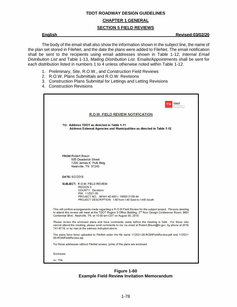
TDOT ROADWAY DESIGN GUIDELINES
CHAPTER 1 GENERAL
SECTION 5 FIELD REVIEWS
English Revised:03/02/20
1-78
The body of the email shall also show the information shown in the subject line, the name of the plan set stored in FileNet, and the date the plans were added to FileNet. The email notification shall be sent to the recipients using email addresses shown in Table 1-12, Internal Email Distribution List and Table 1-13, Mailing Distribution List. Emails/Appointments shall be sent for each distribution listed in numbers 1 to 4 unless otherwise noted within Table 1-12.
1. Preliminary, Site, R.O.W., and Construction Field Reviews 2. R.O.W. Plans Submittals and R.O.W. Revisions 3. Construction Plans Submittal for Lettings and Letting Revisions 4. Construction Revisions
Figure 1-60 Example Field Review Invitation Memorandum
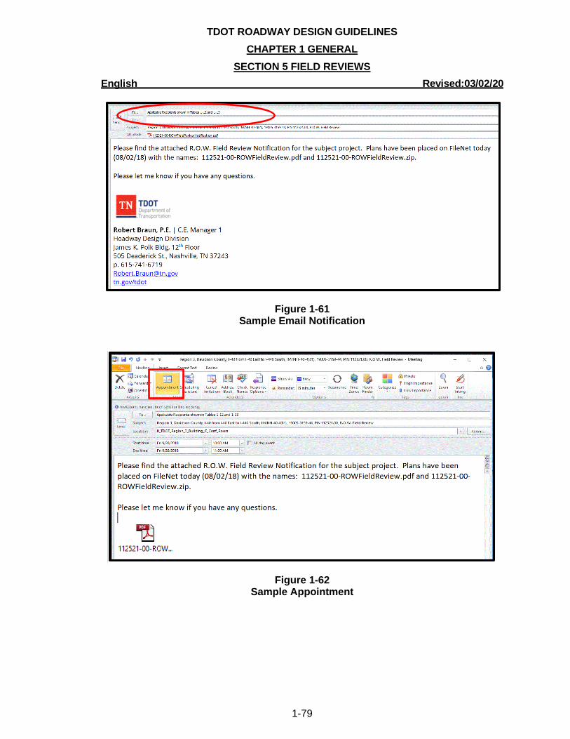
TDOT ROADWAY DESIGN GUIDELINES
CHAPTER 1 GENERAL
SECTION 5 FIELD REVIEWS
English Revised:03/02/20
1-79
Figure 1-61 Sample Email Notification
Figure 1-62 Sample Appointment
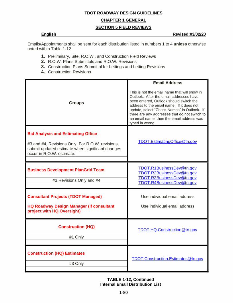
TDOT ROADWAY DESIGN GUIDELINES
CHAPTER 1 GENERAL
SECTION 5 FIELD REVIEWS
English Revised:03/02/20
1-80
Emails/Appointments shall be sent for each distribution listed in numbers 1 to 4 unless otherwise noted within Table 1-12.
1. Preliminary, Site, R.O.W., and Construction Field Reviews
2. R.O.W. Plans Submittals and R.O.W. Revisions
3. Construction Plans Submittal for Lettings and Letting Revisions 4. Construction Revisions
Groups
Email Address
This is not the email name that will show in Outlook. After the email addresses have been entered, Outlook should switch the address to the email name. If it does not update, select “Check Names” in Outlook. If there are any addresses that do not switch to an email name, then the email address was typed in wrong.
Bid Analysis and Estimating Office
#3 and #4, Revisions Only. For R.O.W. revisions, submit updated estimate when significant changes occur in R.O.W. estimate.
Business Development PlanGrid Team
[email protected] [email protected] [email protected] [email protected]
#3 Revisions Only and #4
Consultant Projects (TDOT Managed)
HQ Roadway Design Manager (if consultant project with HQ Oversight)
Use individual email address
Use individual email address
Construction (HQ)
#1 Only
Construction (HQ) Estimates
#3 Only
TABLE 1-12, Continued Internal Email Distribution List
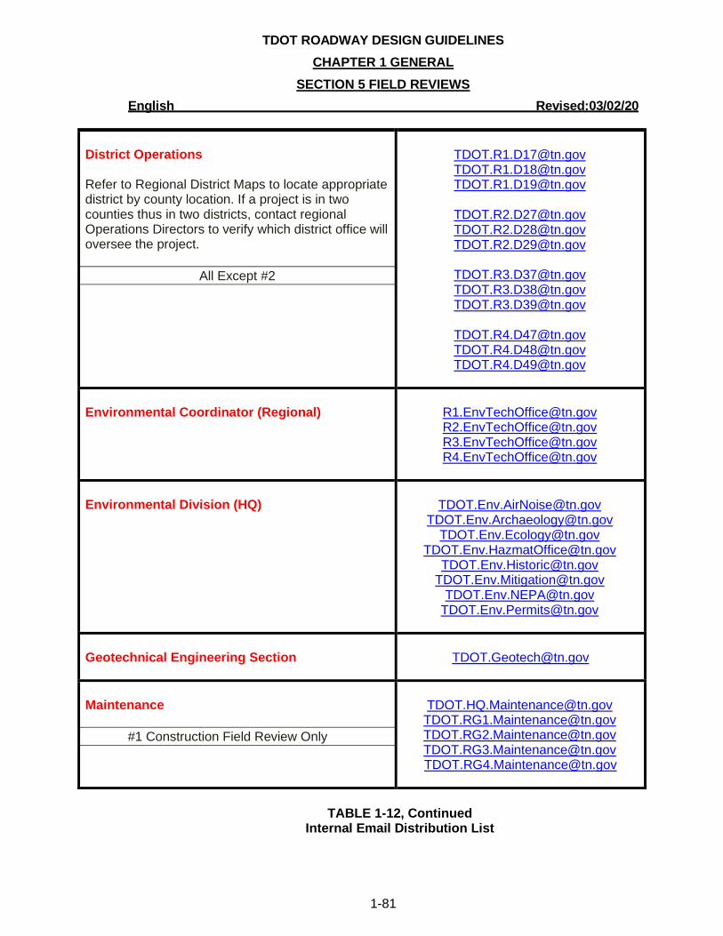
TDOT ROADWAY DESIGN GUIDELINES
CHAPTER 1 GENERAL
SECTION 5 FIELD REVIEWS
English Revised:03/02/20
1-81
District Operations
Refer to Regional District Maps to locate appropriate district by county location. If a project is in two counties thus in two districts, contact regional Operations Directors to verify which district office will oversee the project.
All Except #2
[email protected] [email protected] [email protected]
[email protected] [email protected] [email protected]
[email protected] [email protected] [email protected]
[email protected] [email protected] [email protected]
Environmental Coordinator (Regional)
[email protected] [email protected] [email protected] [email protected]
Environmental Division (HQ)
[email protected] [email protected]
[email protected] [email protected]
[email protected] [email protected]
Geotechnical Engineering Section
Maintenance
#1 Construction Field Review Only
[email protected] [email protected] [email protected] [email protected] [email protected]
TABLE 1-12, Continued Internal Email Distribution List
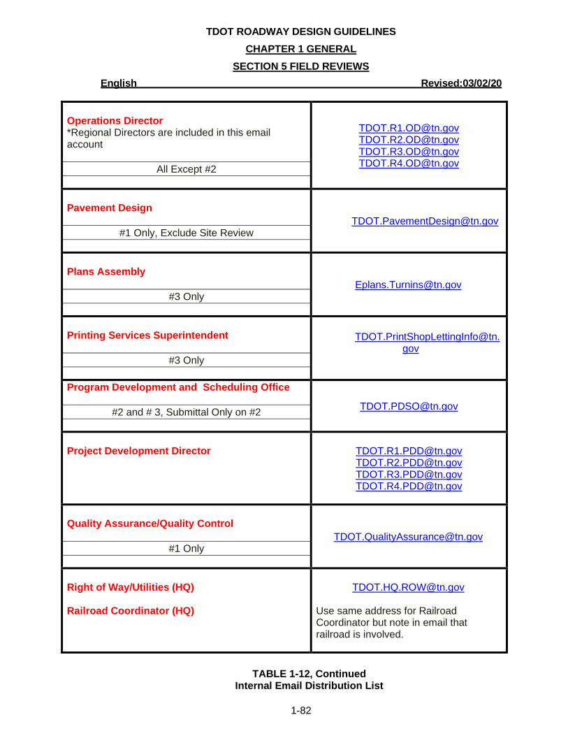
TDOT ROADWAY DESIGN GUIDELINES
CHAPTER 1 GENERAL
SECTION 5 FIELD REVIEWS
English Revised:03/02/20
1-82
Operations Director *Regional Directors are included in this email account
All Except #2
[email protected] [email protected] [email protected] [email protected]
Pavement Design
#1 Only, Exclude Site Review
Plans Assembly
#3 Only
Printing Services Superintendent
#3 Only
Program Development and Scheduling Office
#2 and # 3, Submittal Only on #2
Project Development Director
[email protected] [email protected] [email protected] [email protected]
Quality Assurance/Quality Control
#1 Only
Right of Way/Utilities (HQ)
Railroad Coordinator (HQ)
Use same address for Railroad Coordinator but note in email that railroad is involved.
TABLE 1-12, Continued Internal Email Distribution List
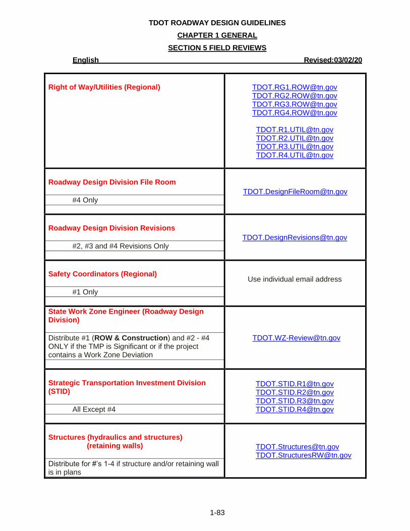
TDOT ROADWAY DESIGN GUIDELINES
CHAPTER 1 GENERAL
SECTION 5 FIELD REVIEWS
English Revised:03/02/20
1-83
Right of Way/Utilities (Regional)
[email protected] [email protected] [email protected] [email protected]
[email protected] [email protected] [email protected] [email protected]
Roadway Design Division File Room
#4 Only
Roadway Design Division Revisions
#2, #3 and #4 Revisions Only
Safety Coordinators (Regional)
#1 Only
Use individual email address
State Work Zone Engineer (Roadway Design Division)
Distribute #1 (ROW & Construction) and #2 - #4 ONLY if the TMP is Significant or if the project contains a Work Zone Deviation
Strategic Transportation Investment Division (STID)
All Except #4
[email protected] [email protected] [email protected] [email protected]
Structures (hydraulics and structures)
(retaining walls)
Distribute for #’s 1-4 if structure and/or retaining wall is in plans

TDOT ROADWAY DESIGN GUIDELINES
CHAPTER 1 GENERAL
SECTION 5 FIELD REVIEWS
English Revised:03/02/20
1-84
Traffic Operations (HQ) (ITS Infrastructure) Traffic Operations (HQ) (Signals, Lighting) Traffic Operations (HQ) (Signing)
Distribute for #1 (Prelim.) to the ITS and Signals and Lighting email accounts. Distribute for #1 (Site, ROW) to all three email accounts. Distribute #1 (Construction) and #2 - #4 only if ITS, signals, lighting, and/or signing is in plans.
Signs
Signals and Lighting
Traffic Engineer (Regional)
#1 Only
Use individual email address
TABLE 1-12, Continued
Internal Email Distribution List
1-502.02 EXTERNAL DISTRIBUTION TO AGENCIES OR MUNICIPALITIES
It is necessary to provide paper copies of the plans to field review invitees outside the
Department including FHWA, county and local officials, and utility owners. The distribution shall
consist of the Field Review Invitation Memorandum (See Figure 1-60, Example Field Review
Invitation Memorandum) and a half-size set of plans. The mailing shall be sent to the recipients in
accordance to Table 1-13, Mailing Distribution List. Field review distribution by mail shall occur on
the same day as the field review distribution by email and appointment.
Paper plans shall be provided to the Federal Highway Administration (FHWA) for new and
reconstruction projects on the Interstate System or for Projects of Divisional Interest (PODI) or
Appalachian Development Projects only. All projects of these types shall have field reviews
scheduled in coordination with the FHWA. FHWA does not require a field review notification for any
other Federal-Aid projects.
Design Managers shall also have the option to email field review notifications and provide
electronic plans as an attachment or to send them on other electronic media, provided the individual
has the capability to print the plans and has agreed to the electronic distribution.
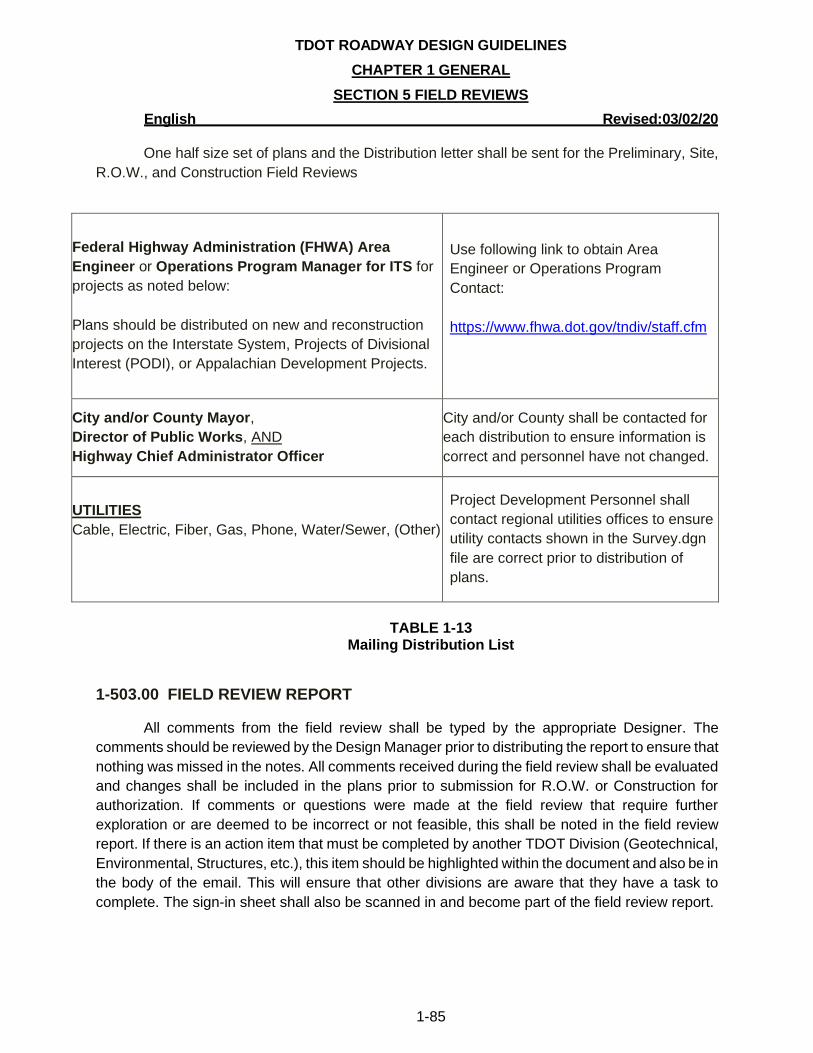
TDOT ROADWAY DESIGN GUIDELINES
CHAPTER 1 GENERAL
SECTION 5 FIELD REVIEWS
English Revised:03/02/20
1-85
One half size set of plans and the Distribution letter shall be sent for the Preliminary, Site,
R.O.W., and Construction Field Reviews
Federal Highway Administration (FHWA) Area
Engineer or Operations Program Manager for ITS for
projects as noted below:
Plans should be distributed on new and reconstruction
projects on the Interstate System, Projects of Divisional
Interest (PODI), or Appalachian Development Projects.
Use following link to obtain Area
Engineer or Operations Program
Contact:
https://www.fhwa.dot.gov/tndiv/staff.cfm
City and/or County Mayor,
Director of Public Works, AND
Highway Chief Administrator Officer
City and/or County shall be contacted for
each distribution to ensure information is
correct and personnel have not changed.
UTILITIES
Cable, Electric, Fiber, Gas, Phone, Water/Sewer, (Other)
Project Development Personnel shall
contact regional utilities offices to ensure
utility contacts shown in the Survey.dgn
file are correct prior to distribution of
plans.
TABLE 1-13
Mailing Distribution List
1-503.00 FIELD REVIEW REPORT
All comments from the field review shall be typed by the appropriate Designer. The
comments should be reviewed by the Design Manager prior to distributing the report to ensure that
nothing was missed in the notes. All comments received during the field review shall be evaluated
and changes shall be included in the plans prior to submission for R.O.W. or Construction for
authorization. If comments or questions were made at the field review that require further
exploration or are deemed to be incorrect or not feasible, this shall be noted in the field review
report. If there is an action item that must be completed by another TDOT Division (Geotechnical,
Environmental, Structures, etc.), this item should be highlighted within the document and also be in
the body of the email. This will ensure that other divisions are aware that they have a task to
complete. The sign-in sheet shall also be scanned in and become part of the field review report.
TDOT ROADWAY DESIGN GUIDELINES
CHAPTER 1 GENERAL
SECTION 5 FIELD REVIEWS
English Revised:03/02/20
1-86
A complete field review report shall be distributed within two weeks after the review to all
attendees, individuals providing comments, and personnel who received the original Field Review
Invitation Memorandum. The Site Review report shall clearly state which retaining walls were
determined to be designed by the Structures Division ([email protected]) and if the
determination was made to hold a Constructability Review (PPRM Activity #690).
Field review reports shall be distributed by email except to those outside the Department
whose e-mail addresses are not available. Field review reports shall be in PDF format. FHWA has
requested the field review reports not be sent for projects which were not attended by a
representative of FHWA.
TDOT ROADWAY DESIGN GUIDELINES
CHAPTER 1 GENERAL
SECTION 6 PUBLIC HEARINGS/MEETINGS
English Revised:03/02/20
1-87
SECTION 6 –PUBLIC HEARINGS/MEETINGS
1-600.00 PUBLIC HEARING AND PUBLIC MEETING REQUIREMENTS
Generally, if a project has R.O.W. acquisition affecting 10 or more tracts, there should be a
public hearing/meeting.
In order to meet all legal requirements for advertising public hearings or public
meetings, the Community Relations Division (CRD) requests that all information pertaining to public
hearings be received within the time frames described in the TDOT Public Involvement Plan. The
TDOT Public Involvement Plan has vital information on the purpose and procedures of the
hearings/meetings, who shall attend the hearings, types of facilities needed, etc. The Public
Involvement Plan which includes document samples such as comment cards, templates, and
checklist for the public hearings/meetings can be found on the Public Involvement &
Communication Office webpage. Fillable forms are also available from the DDocs.zip download
from the Standard Design CADD Files and Documents webpage.
The Manager requesting the public hearing/meeting must complete a Pre-Meeting
Questionnaire a minimum of 60 days prior to the proposed hearing/meeting date. See Figure 1-63,
Example Pre-Meeting Questionnaire. When the date has been approved by the Community
Relations Division (CRD), a Public Meeting/Hearing Notice Request and a Public Meeting/Hearing
Checklist must be sent to the CRD. See Figure 1-64, Example Meeting Notice and Figure 1-65,
Example Meeting Checklist. For Public Meetings, the request and checklist must be submitted four
(4) weeks in advance of the meeting date. For Public Hearings, the request and checklist must be
submitted six (6) weeks in advance of the hearing date. An electronic copy shall be sent via email
and a hard copy shall be mailed. These items should be directed to the personnel listed in the
Public Meeting/Hearing Checklist.
A general location map is needed for newspapers from the Consultant or Design Manager
for design hearings. See Figure 1-66, Example General Location Map. The CRD has requested that
the general location map be submitted as a Microsoft Word document. For guidance in creating a
Word document from a MicroStation drawing refer to the LocationMaps.pdf document located on
the Standard Design CADD Files and Documents webpage.
If there is a proposed alignment change due to comments at the Public Hearing or Public
Meeting, the Design Manager shall notify Geotechnical Engineering Section and Environmental
immediately by email for notification of changes.
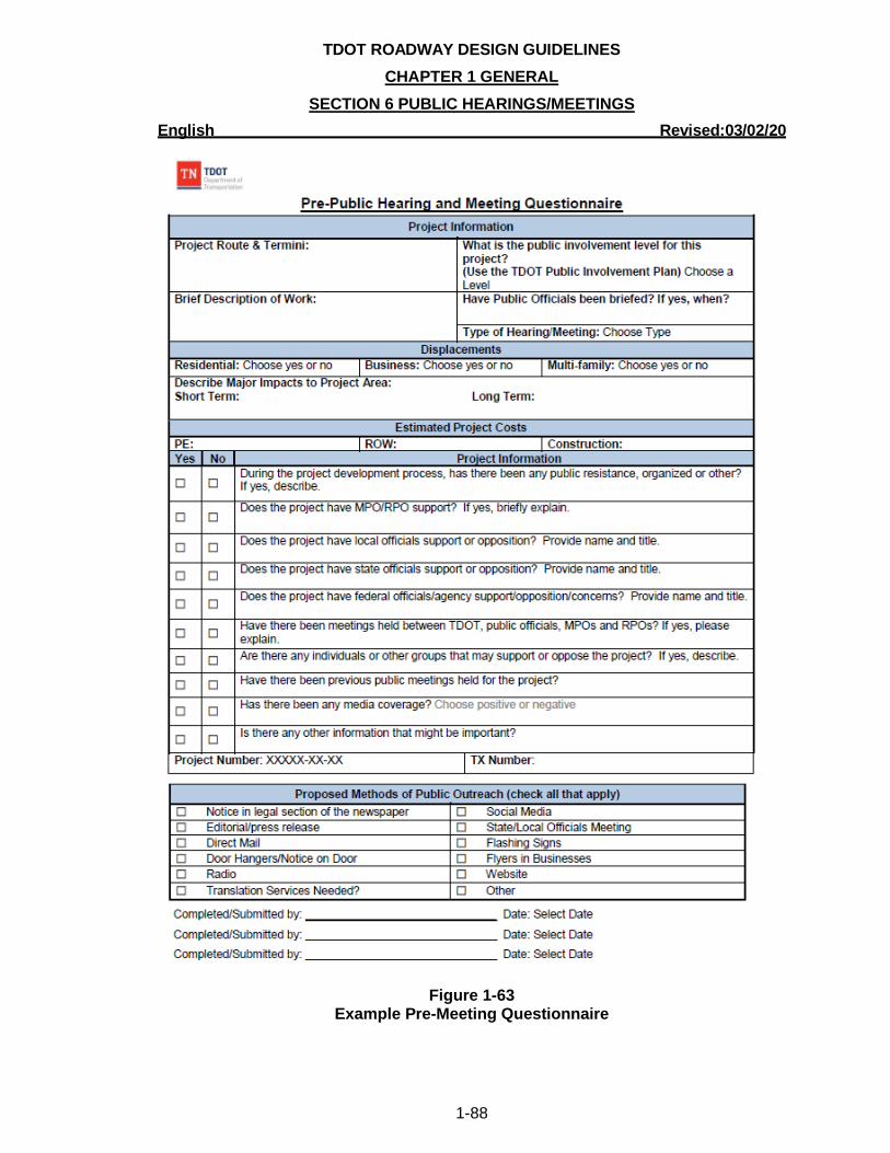
TDOT ROADWAY DESIGN GUIDELINES
CHAPTER 1 GENERAL
SECTION 6 PUBLIC HEARINGS/MEETINGS
English Revised:03/02/20
1-88
Figure 1-63 Example Pre-Meeting Questionnaire

TDOT ROADWAY DESIGN GUIDELINES
CHAPTER 1 GENERAL
SECTION 6 PUBLIC HEARINGS/MEETINGS
English Revised:03/02/20
1-89
Figure 1-64 Example Meeting Notice
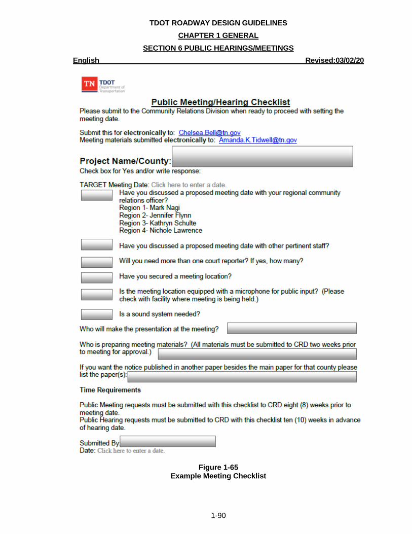
TDOT ROADWAY DESIGN GUIDELINES
CHAPTER 1 GENERAL
SECTION 6 PUBLIC HEARINGS/MEETINGS
English Revised:03/02/20
1-90
Figure 1-65
Example Meeting Checklist
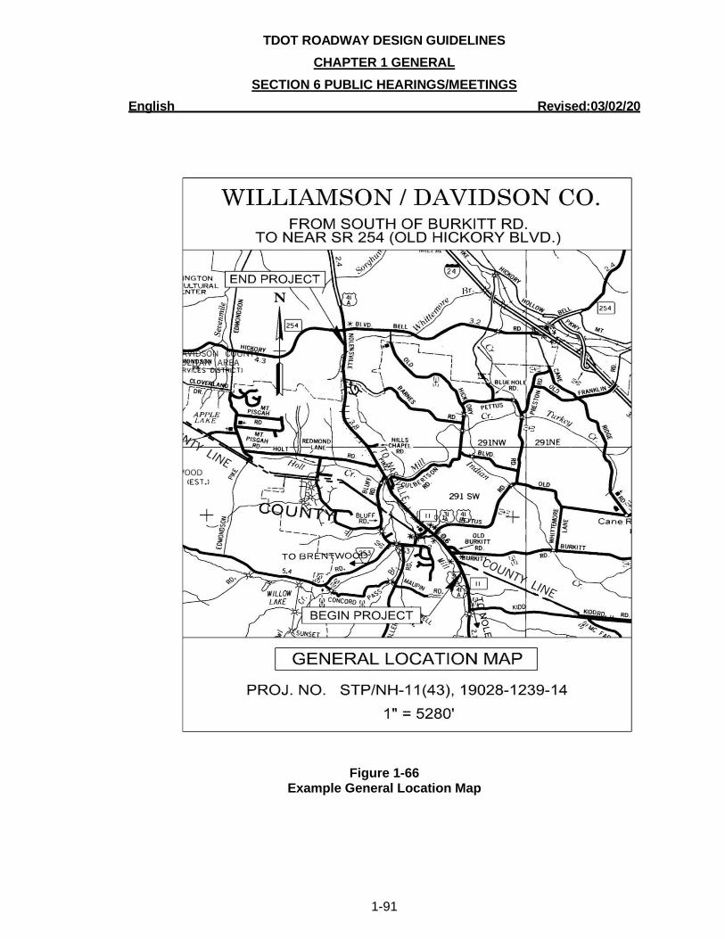
TDOT ROADWAY DESIGN GUIDELINES
CHAPTER 1 GENERAL
SECTION 6 PUBLIC HEARINGS/MEETINGS
English Revised:03/02/20
1-91
Figure 1-66 Example General Location Map
TDOT ROADWAY DESIGN GUIDELINES
CHAPTER 1 GENERAL
SECTION 7 VALUE ENGINEERING English Revised: 03/02/20
1-92
SECTION 7 – VALUE ENGINEERING
1-700.00 VALUE ENGINEERING
Value Engineering is a systematic independent multidisciplinary team review process which
utilizes project functional analysis to develop recommendations that:
• Optimize the value and quality of the project.
• Provide the needed functions, considering community and environmental commitments,
safety, reliability, efficiency, and overall life-cycle cost.
• Reduce the time to develop and deliver the project.
1-701.00 VALUE ENGINEERING OFFICE RESPONSIBILITIES
TDOT has established a VE Program in accordance with 23 CFR Part 627. TDOT shall
designate a VE Program Coordinator, hereinafter referred to as the “Coordinator”, to promote and
advance VE program activities. The program is administered by the Roadway Design Division’s VE
Office. The responsibilities of the VE Office include the following:
• Monitor PPRM and coordinate with TDOT Program Development and Administration to
identify projects that meet the project selection criteria.
• Ensure that VE analyses are conducted on all applicable projects.
• Coordinate all VE training requirements.
• Provide a list of current and potential VE projects on a quarterly basis to the FHWA.
• Provide an annual report to FHWA summarizing the results of the VE analyses.
• Coordinate with HQ Construction Office to fulfill any Program Performance Data requested
by FHWA.
1-702.00 VALUE ENGINEERING PROJECT SELECTION POLICY
A VE analysis shall be conducted as early as practicable on all applicable projects
developed by TDOT and Local Agencies that utilize federal-aid highway funding.
Applicable projects requiring VE analysis include the following:
a) Projects that are located on the National Highway System (NHS), utilize federal-aid
highway funding, and have an estimated total project cost greater than or equal to $50
million.
b) Bridge projects that are located on the NHS, utilize federal-aid highway funding, and have
an estimated total project cost greater than or equal to $40 million.
TDOT ROADWAY DESIGN GUIDELINES
CHAPTER 1 GENERAL
SECTION 7 VALUE ENGINEERING English Revised: 03/02/20
1-93
c) Any major project (as defined in 23 U.S.C. 106(h)) that is located on or off of the NHS and
utilizes Federal-aid highway funding in any contract or phase comprising the major
project.
d) Any project for which a VE analysis has not been conducted and a change is made to the
project's scope or design between the final design and the construction Letting that results
in an increase in the project's total cost such that it meets the thresholds identified in
bullets a), b), or c) above.
e) Any other project which utilizes federal-aid highway program funding that FHWA
determines to be appropriate. Design Build Projects do not require a VE analysis, but
Construction Manager/General Contractor (CM/GC) projects do require a VE analysis if it
meets the thresholds identified in bullets a), b), or c) above.
The total project cost is defined as the estimated costs of all work to be conducted on a project
including the environmental, design, r.o.w., utilities, and construction phases. A bridge project is
defined as any project whose primary purpose is to construct, reconstruct, rehabilitate, resurface, or
restore a bridge. For projects split into smaller sections for development, the termini used in the
environmental document shall control and be used for determining threshold requirements.
TDOT and Local Agencies may elect, on a case by case basis, to conduct a VE analysis
on other complex projects if there is a potential to realize benefits from the analysis. Design
Managers and Division Heads are encouraged to notify the Coordinator of any projects that they
think have the potential to benefit from a VE analysis.
1-703.00 VALUE ENGINEERING ANALYSIS PROCEDURES
1-703.01 IDENTIFYING AND SCHEDULING VALUE ENGINEERING ANALYSIS
The Coordinator shall determine when the VE analysis will take place. The VE analysis shall
be conducted as early as practicable during the project development. In most cases, the VE
analysis shall be scheduled prior to Right-of-Way field review.
When a project has been identified as a candidate for VE analysis, the Coordinator shall
notify the Roadway Design Manager. The Roadway Design Manager shall then notify the
Coordinator of any changes made to the project scope during the project development.
TDOT ROADWAY DESIGN GUIDELINES
CHAPTER 1 GENERAL
SECTION 7 VALUE ENGINEERING English Revised: 03/02/20
1-94
1-703.02 ASSEMBLING THE VALUE ENGINEERING ANALYSIS TEAM
The Coordinator shall select a multidisciplinary team composed of individuals who are not
directly involved in the project’s planning or design. The team shall include members from key
project disciplines such as Roadway, Structures, Environmental, Geotechnical, Construction,
Hydraulics, Materials and Test, Traffic Operations, Strategic Transportation Investments, and
Quality Assurance/Quality Control (QA/QC).
The Coordinator will select the team leader and they will work together during the planning
and scheduling of the VE analysis. The team leader will guide the team during the project analysis
and the Coordinator shall oversee the team’s progress to ensure that the VE analysis process, as
defined in 23 CFR Part 627.3, is followed.
1-703.03 VALUE ENGINEERING JOB PLAN
The VE team analysis shall follow the VE Job Plan, which consists of seven phases as
defined in 23 CFR Part 627.3(f). Prior to the beginning of the VE team analysis, the Coordinator will
scale the level of analysis conducted and effort expended for each phase to meet the needs of each
individual project and convey this plan of analysis to the team leader.
Analyze Project Functions:
1. Information Phase: Review project information, including commitments and constraints, and
identify and define the current project conditions and overall analysis goals.
2. Function Analysis Phase: Analyze the project information to understand the required
functions of the project and define each required function using a two-word active verb/
measurable noun technique.
Generate Alternatives:
3. Creative Phase: Generate ideas to identify other ways to accomplish the required functions
which improve the project’s performance, enhance its quality, and/or lower its costs.
4. Evaluation Phase: Evaluate advantages and disadvantages for each design alternative,
including life-cycle costs, and the need for additional environmental studies. Select feasible
ideas for development.
Act on Recommendations:
5. Development Phase: Develop each selected alternative, including environmental, technical
and cost supporting data, into fully supported recommendations
6. Presentation Phase: Present the VE recommendations to TDOT management and/or the
Roadway Design Manager.
TDOT ROADWAY DESIGN GUIDELINES
CHAPTER 1 GENERAL
SECTION 7 VALUE ENGINEERING English Revised: 03/02/20
1-95
7. Resolution Phase: The Coordinator will evaluate, document, and ensure implementation of
all approved VE recommendations.
1-703.04 PRESENTATION OF RECOMMENDATIONS
The Coordinator and team leader will work together to create a VE Recommendations
Report which includes analysis and cost information for each recommendation. The total estimated
VE cost saving for all recommendations will determine how the recommendations are presented.
• For savings totaling $1 million or less, the VE Recommendations Report will be presented to
the Roadway Design Manager and/or Regional Project Development Director (PDD) for
their evaluation and response.
• For savings totaling more than $1 million, a team member presentation of all
recommendations will be made to TDOT management. The VE Recommendation Report
will be available for all presentation attendees. A copy of the VE Recommendations Report
shall be given to the Roadway Design Manager for their evaluation and response prior to
the presentation.
The Coordinator will request a written response to each recommendation from the Roadway
Design Manager. This written response shall explain whether or not the recommendation is found
feasible to implement. The team presentation to TDOT Management shall also include any
discussions and/or decisions made during the presentation.
1-704.00 VALUE ENGINEERING WORKBOOKS
After the response to all VE recommendations has been received from TDOT Management,
the Coordinator shall assemble the VE Workbook. This Workbook shall include all Job Plan forms
and all correspondence with TDOT Management. The Coordinator shall distribute the completed VE
Workbook to the Roadway Design Manager and forward the VE workbook to the FHWA office. A
copy shall be retained by the VE Office for at least 3 (three) years after the final acceptance of
construction.
1-705.00 IMPLEMENTATIONS OF APPROVED RECOMMENDATIONS
The Coordinator shall oversee the implementation of all accepted VE recommendations.
The Roadway Design Manager shall be responsible for incorporating all accepted VE
recommendations into the project prior to finalizing the construction plans. If the Roadway Design
Manager determines that any accepted VE recommendation is no longer acceptable, he/she shall
notify the Coordinator and provide, in writing, the reason(s) for the changes. These changes shall
be evaluated to determine if any additional action can be taken to modify the recommendation. The
TDOT ROADWAY DESIGN GUIDELINES
CHAPTER 1 GENERAL
SECTION 7 VALUE ENGINEERING English Revised: 03/02/20
1-96
Coordinator shall review the final construction plans to ensure all accepted VE recommendations
have been implemented.