Embed Size (px)
Citation preview

CCHHAAPPTTEERR 11
Solution Manual for Mechanics of Materials 7th Edition by Beer
Full file at https://TestbankDirect.eu/
Full file at https://TestbankDirect.eu/
Solution Manual for Mechanics of Materials 7th Edition by Beer
Full file at https://TestbankDirect.eu/
Full file at https://TestbankDirect.eu/

PROPRIETARY MATERIAL. Copyright © 2015 McGraw-Hill Education. This is proprietary material solely for authorized instructor use.
Not authorized for sale or distribution in any manner. This document may not be copied, scanned, duplicated, forwarded, distributed, or posted
on a website, in whole or part.
3
d1d2
125 kN
125 kN
60 kN
CA
B
0.9 m 1.2 m
PROBLEM 1.1
Two solid cylindrical rods AB and BC are welded together at B and loaded as shown. Knowing that 1 30 mmd and 2 50 mm,d find the average normal stress at the midsection of (a) rod AB, (b) rod BC.
SOLUTION
(a) Rod AB:
Force: 360 10 N tensionP
Area: 2 3 2 6 21 (30 10 ) 706.86 10 m
4 4A d
Normal stress: 3
66
60 1084.882 10 Pa
706.86 10AB
P
A
84.9 MPaAB
(b) Rod BC:
Force: 3 3 360 10 (2)(125 10 ) 190 10 NP
Area: 2 3 2 3 22 (50 10 ) 1.96350 10 m
4 4A d
Normal stress: 3
63
190 1096.766 10 Pa
1.96350 10BC
P
A
96.8 MPaBC
Solution Manual for Mechanics of Materials 7th Edition by Beer
Full file at https://TestbankDirect.eu/
Full file at https://TestbankDirect.eu/
PROPRIETARY MATERIAL. Copyright © 2015 McGraw-Hill Education. This is proprietary material solely for authorized instructor use.
Not authorized for sale or distribution in any manner. This document may not be copied, scanned, duplicated, forwarded, distributed, or posted
on a website, in whole or part.
4
d1d2
125 kN
125 kN
60 kN
CA
B
0.9 m 1.2 m
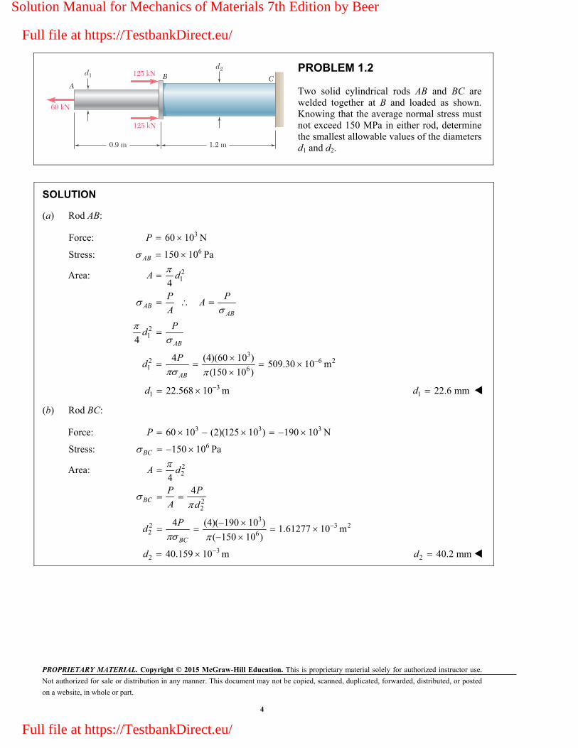
PROBLEM 1.2
Two solid cylindrical rods AB and BC are welded together at B and loaded as shown. Knowing that the average normal stress must not exceed 150 MPa in either rod, determine the smallest allowable values of the diameters d1 and d2.
SOLUTION
(a) Rod AB:
Force: 360 10 NP
Stress: 6150 10 PaAB
Area: 214
A d
21
32 6 21 6
4
4 (4)(60 10 )509.30 10 m
(150 10 )
ABAB
AB
AB
P PA
A
Pd
Pd
31 22.568 10 md 1 22.6 mmd
(b) Rod BC:
Force: 3 3 360 10 (2)(125 10 ) 190 10 NP
Stress: 6150 10 PaBC
Area: 224
A d
22
32 3 22 6
4
4 (4)( 190 10 )1.61277 10 m
( 150 10 )
BC
BC
P P
A d
Pd
32 40.159 10 md 2 40.2 mmd
Solution Manual for Mechanics of Materials 7th Edition by Beer
Full file at https://TestbankDirect.eu/
Full file at https://TestbankDirect.eu/

PROPRIETARY MATERIAL. Copyright © 2015 McGraw-Hill Education. This is proprietary material solely for authorized instructor use.
Not authorized for sale or distribution in any manner. This document may not be copied, scanned, duplicated, forwarded, distributed, or posted
on a website, in whole or part.
5
0.75 in.
1.25 in.
12 kips
P
B
C
25 in.
30 in.
A
PROBLEM 1.3
Two solid cylindrical rods AB and BC are welded together at B and loaded as shown. Knowing that P = 10 kips, find the average normal stress at the midsection of (a) rod AB, (b) rod BC.
SOLUTION
(a) Rod AB:
2 2 21
12 10 22 kips
(1.25) 1.22718 in4 4
2217.927 ksi
1.22718AB
P
A d
P
A
17.93 ksiAB
(b) Rod BC:
2 2 22
10 kips
(0.75) 0.44179 in4 4
1022.635 ksi
0.44179AB
P
A d
P
A
22.6 ksiAB
Solution Manual for Mechanics of Materials 7th Edition by Beer
Full file at https://TestbankDirect.eu/
Full file at https://TestbankDirect.eu/

PROPRIETARY MATERIAL. Copyright © 2015 McGraw-Hill Education. This is proprietary material solely for authorized instructor use.
Not authorized for sale or distribution in any manner. This document may not be copied, scanned, duplicated, forwarded, distributed, or posted
on a website, in whole or part.
6
0.75 in.
1.25 in.
12 kips
P
B
C
25 in.
30 in.
A
PROBLEM 1.4
Two solid cylindrical rods AB and BC are welded together at B and loaded as shown. Determine the magnitude of the force P for which the tensile stresses in rods AB and BC are equal.
SOLUTION
(a) Rod AB:
22
2
2
12 kips
(1.25 in.)4 4
1.22718 in
12 kips
1.22718 inAB
P P
dA
A
P
(b) Rod BC:
2 2
2
2
(0.75 in.)4 4
0.44179 in
0.44179 inBC
P P
A d
A
P
2 2
12 kips
1.22718 in 0.44179 in5.3015 0.78539
AB BC
P P
P
6.75 kipsP
Solution Manual for Mechanics of Materials 7th Edition by Beer
Full file at https://TestbankDirect.eu/
Full file at https://TestbankDirect.eu/

PROPRIETARY MATERIAL. Copyright © 2015 McGraw-Hill Education. This is proprietary material solely for authorized instructor use.
Not authorized for sale or distribution in any manner. This document may not be copied, scanned, duplicated, forwarded, distributed, or posted
on a website, in whole or part.
7
1200 N
1200 N
C
A
B
PROBLEM 1.5
A strain gage located at C on the surface of bone AB indicates that the average normal stress in the bone is 3.80 MPa when the bone is subjected to two 1200-N forces as shown. Assuming the cross section of the bone at C to be annular and knowing that its outer diameter is 25 mm, determine the inner diameter of the bone’s cross section at C.
SOLUTION
P P
AA
Geometry: 2 21 2( )
4
A d d
2 2 22 1 1
2 3 22 6
6 2
32
4 4
(4)(1200)(25 10 )
(3.80 10 )
222.92 10 m
14.93 10 m
A Pd d d
d
d 2 14.93 mmd
Solution Manual for Mechanics of Materials 7th Edition by Beer
Full file at https://TestbankDirect.eu/
Full file at https://TestbankDirect.eu/

PROPRIETARY MATERIAL. Copyright © 2015 McGraw-Hill Education. This is proprietary material solely for authorized instructor use.
Not authorized for sale or distribution in any manner. This document may not be copied, scanned, duplicated, forwarded, distributed, or posted
on a website, in whole or part.
8
100 m
15 mm
10 mm b
a
B
C
A
PROBLEM 1.6
Two brass rods AB and BC, each of uniform diameter, will be brazed together at B to form a nonuniform rod of total length 100 m, which will be suspended from a support at A as shown. Knowing that the density of brass is 8470 kg/m3, determine (a) the length of rod AB for which the maximum normal stress in ABC is minimum, (b) the corresponding value of the maximum normal stress.
SOLUTION
Areas: 2 2 6 2
2 2 6 2
(15 mm) 176.715 mm 176.715 10 m4
(10 mm) 78.54 mm 78.54 10 m4
AB
BC
A
A
From geometry, b 100 a
Weights: 6
6
(8470)(9.81)(176.715 10 ) 14.683
(8470)(9.81)(78.54 10 )(100 ) 652.59 6.526
AB AB AB
BC BC BC
W g A a a
W g A a a
Normal stresses:
At A,
6 3
652.59 8.157
3.6930 10 46.160 10
A AB BC
AA
AB
P W W a
Pa
A
(1)
At B,
6 3
652.59 6.526
8.3090 10 83.090 10
B BC
BB
BC
P W a
Pa
A
(2)
(a) Length of rod AB. The maximum stress in ABC is minimum when A B or
6 34.6160 10 129.25 10 0 a
35.71 ma 35.7 m AB a
(b) Maximum normal stress.
6 3
6 3
6
3.6930 10 (46.160 10 )(35.71)
8.3090 10 (83.090 10 )(35.71)
5.34 10 Pa
A
B
A B 5.34 MPa
Solution Manual for Mechanics of Materials 7th Edition by Beer
Full file at https://TestbankDirect.eu/
Full file at https://TestbankDirect.eu/

PROPRIETARY MATERIAL. Copyright © 2015 McGraw-Hill Education. This is proprietary material solely for authorized instructor use.
Not authorized for sale or distribution in any manner. This document may not be copied, scanned, duplicated, forwarded, distributed, or posted
on a website, in whole or part.
9
0.2 m0.25 m
0.4 m
20 kN
C
B
AD
E
PROBLEM 1.7
Each of the four vertical links has an 8 36-mm uniform rectangular cross section and each of the four pins has a 16-mm diameter. Determine the maximum value of the average normal stress in the links connecting (a) points B and D, (b) points C and E.
SOLUTION
Use bar ABC as a free body.
3
3
3
3
0 : (0.040) (0.025 0.040)(20 10 ) 0
32.5 10 N Link is in tension.
0 : (0.040) (0.025)(20 10 ) 0
12.5 10 N Link is in compression.
C BD
BD
B CE
CE
M F
F BD
M F
F CE
Net area of one link for tension (0.008)(0.036 0.016) 6 2160 10 m
For two parallel links, 6 2net 320 10 m A
(a) 3
66
net
32.5 10101.563 10
320 10BD
BDF
A
101.6 MPa BD
Area for one link in compression (0.008)(0.036) 6 2288 10 m
For two parallel links, 6 2576 10 m A
(b) 3
66
12.5 1021.701 10
576 10CE
CEF
A
21.7 MPa CE
Solution Manual for Mechanics of Materials 7th Edition by Beer
Full file at https://TestbankDirect.eu/
Full file at https://TestbankDirect.eu/

PROPRIETARY MATERIAL. Copyright © 2015 McGraw-Hill Education. This is proprietary material solely for authorized instructor use.
Not authorized for sale or distribution in any manner. This document may not be copied, scanned, duplicated, forwarded, distributed, or posted
on a website, in whole or part.
10
10 in. 8 in.
2 in.
12 in.
4 in.
30�
120 lb
120 lb
C
A
B
PROBLEM 1.8
Link AC has a uniform rectangular cross section 18
in. thick and 1 in. wide.
Determine the normal stress in the central portion of the link.
SOLUTION
Use the plate together with two pulleys as a free body. Note that the cable tension causes at 1200 lb-in. clockwise couple to act on the body.
0: (12 4)( cos30 ) (10)( sin 30 ) 1200 lb 0
1200 lb135.500 lb
16 cos30 10 sin 30
B AC AC
AC
M F F
F
Area of link AC: 211 in. in. 0.125 in
8 A
Stress in link AC: 135.50
1084 psi 1.084 ksi0.125
ACAC
F
A
Solution Manual for Mechanics of Materials 7th Edition by Beer
Full file at https://TestbankDirect.eu/
Full file at https://TestbankDirect.eu/

PROPRIETARY MATERIAL. Copyright © 2015 McGraw-Hill Education. This is proprietary material solely for authorized instructor use.
Not authorized for sale or distribution in any manner. This document may not be copied, scanned, duplicated, forwarded, distributed, or posted
on a website, in whole or part.
11
0.100 m
0.150 m 0.300 m 0.250 m
P P P
E
A B C D
PROBLEM 1.9
Three forces, each of magnitude P 4 kN, are applied to the mechanism shown. Determine the cross-sectional area of the uniform portion of rod BE for which the normal stress in that portion is 100 MPa.
SOLUTION
Draw free body diagrams of AC and CD.
Free Body CD: 0: 0.150 0.250 0
0.6
DM P C
C P
Free Body AC: 0: 0.150 0.350 0.450 0.450 0
1.077.1333 (7.133)(4 kN) 28.533 kN
0.150
A BE
BE
M F P P C
F P P
Required area of BE:
36 2
6
28.533 10285.33 10 m
100 10
BEBE
BE
BEBE
BE
F
A
FA
2285 mmBEA
Solution Manual for Mechanics of Materials 7th Edition by Beer
Full file at https://TestbankDirect.eu/
Full file at https://TestbankDirect.eu/

PROPRIETARY MATERIAL. Copyright © 2015 McGraw-Hill Education. This is proprietary material solely for authorized instructor use.
Not authorized for sale or distribution in any manner. This document may not be copied, scanned, duplicated, forwarded, distributed, or posted
on a website, in whole or part.
12
4 kips
308
u6 in.
12 in.
D
C
B
A
PROBLEM 1.10
Link BD consists of a single bar 1 in. wide and 12
in. thick. Knowing that each pin has a 38
-in.
diameter, determine the maximum value of the average normal stress in link BD if (a) = 0, (b) = 90.
SOLUTION
Use bar ABC as a free body.
(a) 0.
0: (18 sin 30 )(4) (12 cos30 ) 0
3.4641 kips (tension)
A BD
BD
M F
F
Area for tension loading: 23 1( ) 1 0.31250 in
8 2
A b d t
Stress: 2
3.4641 kips
0.31250 inBDF
A 11.09 ksi
(b) 90 .
0: (18 cos30 )(4) (12 cos30 ) 0
6 kips i.e. compression.
A BD
BD
M F
F
Area for compression loading: 21(1) 0.5 in
2A bt
Stress: 2
6 kips
0.5 inBDF
A
12.00 ksi
Solution Manual for Mechanics of Materials 7th Edition by Beer
Full file at https://TestbankDirect.eu/
Full file at https://TestbankDirect.eu/

PROPRIETARY MATERIAL. Copyright © 2015 McGraw-Hill Education. This is proprietary material solely for authorized instructor use.
Not authorized for sale or distribution in any manner. This document may not be copied, scanned, duplicated, forwarded, distributed, or posted
on a website, in whole or part.
13
9 ft
80 kips 80 kips 80 kips
9 ft 9 ft 9 ft
12 ft
B D F
HGEC
A
PROBLEM 1.11
For the Pratt bridge truss and loading shown, determine the average normal stress in member BE, knowing that the cross-sectional area of that member is 5.87 in2.
SOLUTION
Use entire truss as free body.
0: (9)(80) (18)(80) (27)(80) 36 0
120 kips
H y
y
M A
A
Use portion of truss to the left of a section cutting members BD, BE, and CE.
120: 120 80 0 50 kips
15y BE BEF F F
2
50 kips
5.87 in BE
BEF
A
8.52 ksi BE
Solution Manual for Mechanics of Materials 7th Edition by Beer
Full file at https://TestbankDirect.eu/
Full file at https://TestbankDirect.eu/
PROPRIETARY MATERIAL. Copyright © 2015 McGraw-Hill Education. This is proprietary material solely for authorized instructor use.
Not authorized for sale or distribution in any manner. This document may not be copied, scanned, duplicated, forwarded, distributed, or posted
on a website, in whole or part.
14
40 in.
45 in.
15 in.
4 in.
AB C
D E F
4 in.
30 in.
30 in.
480 lb
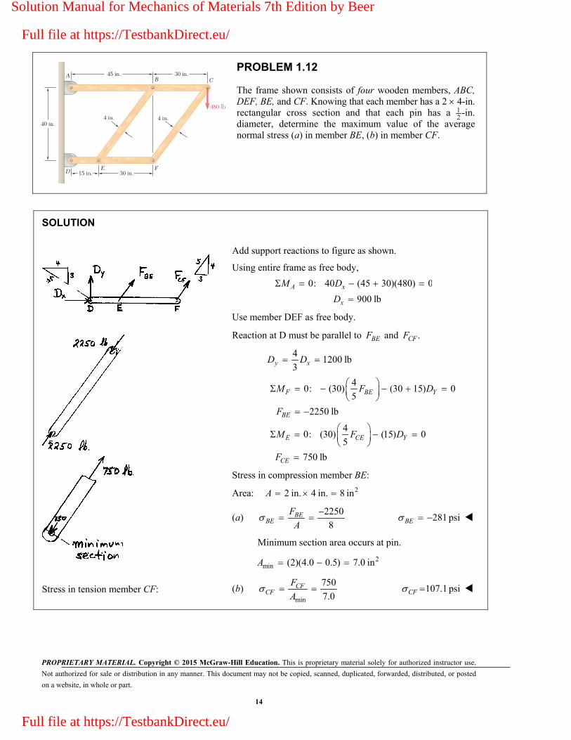
PROBLEM 1.12
The frame shown consists of four wooden members, ABC, DEF, BE, and CF. Knowing that each member has a 2 4-in. rectangular cross section and that each pin has a 1
2-in.
diameter, determine the maximum value of the average normal stress (a) in member BE, (b) in member CF.
SOLUTION
Stress in tension member CF:
Add support reactions to figure as shown.
Using entire frame as free body,
0: 40 (45 30)(480) 0
900 lb
A x
x
M D
D
Use member DEF as free body.
Reaction at D must be parallel to BEF and .CFF
4
1200 lb3
y xD D
40: (30) (30 15) 0
5
2250 lb
40: (30) (15) 0
5
750 lb
F BE Y
BE
E CE Y
CE
M F D
F
M F D
F
Stress in compression member BE:
Area: 22 in. 4 in. 8 in A
(a) 2250
8
BEBE
F
A 281 psi BE
Minimum section area occurs at pin.
2min (2)(4.0 0.5) 7.0 in A
(b) min
750
7.0 CF
CFF
A 107.1 psi CF
Solution Manual for Mechanics of Materials 7th Edition by Beer
Full file at https://TestbankDirect.eu/
Full file at https://TestbankDirect.eu/

PROPRIETARY MATERIAL. Copyright © 2015 McGraw-Hill Education. This is proprietary material solely for authorized instructor use.
Not authorized for sale or distribution in any manner. This document may not be copied, scanned, duplicated, forwarded, distributed, or posted
on a website, in whole or part.
15
D
B
E
A
Dimensions in mm
100
450
250
850
1150
500 675 825
CG
F
PROBLEM 1.13
An aircraft tow bar is positioned by means of a single hydraulic cylinder connected by a 25-mm-diameter steel rod to two identical arm-and-wheel units DEF. The mass of the entire tow bar is 200 kg, and its center of gravity is located at G. For the position shown, determine the normal stress in the rod.
SOLUTION
FREE BODY – ENTIRE TOW BAR:
2(200 kg)(9.81 m/s ) 1962.00 N
0: 850 1150(1962.00 N) 0
2654.5 N
A
W
M R
R
FREE BODY – BOTH ARM & WHEEL UNITS:
100
tan 8.4270675
2
0: ( cos )(550) (500) 0
500(2654.5 N)
550 cos 8.4270
2439.5 N (comp.)
2439.5 N
(0.0125 m)
E CD
CD
CDCD
CD
M F R
F
F
A
64.9697 10 Pa 4.97 MPa CD
Solution Manual for Mechanics of Materials 7th Edition by Beer
Full file at https://TestbankDirect.eu/
Full file at https://TestbankDirect.eu/

PROPRIETARY MATERIAL. Copyright © 2015 McGraw-Hill Education. This is proprietary material solely for authorized instructor use.
Not authorized for sale or distribution in any manner. This document may not be copied, scanned, duplicated, forwarded, distributed, or posted
on a website, in whole or part.
16
CAB
E F G
D
200 mm150 mm
150 mm
300 mm
400 mm
600 mm800 N
PROBLEM 1.14
Two hydraulic cylinders are used to control the position of the robotic arm ABC. Knowing that the control rods attached at A and D each have a 20-mm diameter and happen to be parallel in the position shown, determine the average normal stress in (a) member AE, (b) member DG.
SOLUTION
Use member ABC as free body.
3
40: (0.150) (0.600)(800) 0
5
4 10 N
B AE
AE
M F
F
Area of rod in member AE is 2 3 2 6 2(20 10 ) 314.16 10 m4 4
A d
Stress in rod AE: 3
66
4 1012.7324 10 Pa
314.16 10AE
AEF
A
(a) 12.73 MPaAE
Use combined members ABC and BFD as free body.
4 40: (0.150) (0.200) (1.050 0.350)(800) 0
5 5
1500 N
F AE DG
DG
M F F
F
Area of rod DG: 2 3 2 6 2(20 10 ) 314.16 10 m4 4
A d
Stress in rod DG: 66
15004.7746 10 Pa
3.1416 10DG
DGF
A
(b) 4.77 MPaDG
Solution Manual for Mechanics of Materials 7th Edition by Beer
Full file at https://TestbankDirect.eu/
Full file at https://TestbankDirect.eu/

PROPRIETARY MATERIAL. Copyright © 2015 McGraw-Hill Education. This is proprietary material solely for authorized instructor use.
Not authorized for sale or distribution in any manner. This document may not be copied, scanned, duplicated, forwarded, distributed, or posted
on a website, in whole or part.
17
PROBLEM 1.15
Determine the diameter of the largest circular hole that can be punched into a sheet of polystyrene 6 mm thick, knowing that the force exerted by the punch is 45 kN and that a 55-MPa average shearing stress is required to cause the material to fail.
SOLUTION
For cylindrical failure surface: A dt
Shearing stress: orP P
AA
Therefore, P
dt
Finally,
3
6
3
45 10 N
(0.006 m)(55 10 Pa)
43.406 10 m
Pd
t
43.4 mmd
Solution Manual for Mechanics of Materials 7th Edition by Beer
Full file at https://TestbankDirect.eu/
Full file at https://TestbankDirect.eu/

PROPRIETARY MATERIAL. Copyright © 2015 McGraw-Hill Education. This is proprietary material solely for authorized instructor use.
Not authorized for sale or distribution in any manner. This document may not be copied, scanned, duplicated, forwarded, distributed, or posted
on a website, in whole or part.
18
2 in.
1 in.P' 2 in.
1 in. 9 in.P
in.58
in.58
PROBLEM 1.16
Two wooden planks, each 12
in. thick and 9 in. wide, are joined by the dry mortise joint shown. Knowing that the wood used shears off along its grain when the average shearing stress reaches 1.20 ksi, determine the magnitude P of the axial load that will cause the joint to fail.
SOLUTION
Six areas must be sheared off when the joint fails. Each of these areas has dimensions 5 18 2
in. in., its area
being
2 25 1 5in 0.3125 in
8 2 16 A
At failure, the force carried by each area is
2(1.20 ksi)(0.3125 in ) 0.375 kips F A
Since there are six failure areas,
6 (6)(0.375) P F 2.25 kipsP
Solution Manual for Mechanics of Materials 7th Edition by Beer
Full file at https://TestbankDirect.eu/
Full file at https://TestbankDirect.eu/

PROPRIETARY MATERIAL. Copyright © 2015 McGraw-Hill Education. This is proprietary material solely for authorized instructor use.
Not authorized for sale or distribution in any manner. This document may not be copied, scanned, duplicated, forwarded, distributed, or posted
on a website, in whole or part.
19
0.6 in.
3 in. WoodSteel
PP'
PROBLEM 1.17
When the force P reached 1600 lb, the wooden specimen shown failed in shear along the surface indicated by the dashed line. Determine the average shearing stress along that surface at the time of failure.
SOLUTION
Area being sheared: 23 in. 0.6 in. 1.8 in A
Force: 1600 lbP
Shearing stress: 22
1600 lb8.8889 10 psi
1.8 in
P
A 889 psi
Solution Manual for Mechanics of Materials 7th Edition by Beer
Full file at https://TestbankDirect.eu/
Full file at https://TestbankDirect.eu/

PROPRIETARY MATERIAL. Copyright © 2015 McGraw-Hill Education. This is proprietary material solely for authorized instructor use.
Not authorized for sale or distribution in any manner. This document may not be copied, scanned, duplicated, forwarded, distributed, or posted
on a website, in whole or part.
20
40 mm
8 mm
12 mm
P
10 mm
PROBLEM 1.18
A load P is applied to a steel rod supported as shown by an aluminum plate into which a 12-mm-diameter hole has been drilled. Knowing that the shearing stress must not exceed 180 MPa in the steel rod and 70 MPa in the aluminum plate, determine the largest load P that can be applied to the rod.
SOLUTION
For steel: 1
6 2
(0.012 m)(0.010 m)
376.99 10 m
A dt
6 2 6
1 1 1
3
(376.99 10 m )(180 10 Pa)
67.858 10 N
PP A
A
For aluminum: 3 22 (0.040 m)(0.008 m) 1.00531 10 mA dt
3 2 6 32 2 2
2
(1.00531 10 m )(70 10 Pa) 70.372 10 NP
P AA
Limiting value of P is the smaller value, so 67.9 kNP
Solution Manual for Mechanics of Materials 7th Edition by Beer
Full file at https://TestbankDirect.eu/
Full file at https://TestbankDirect.eu/

PROPRIETARY MATERIAL. Copyright © 2015 McGraw-Hill Education. This is proprietary material solely for authorized instructor use.
Not authorized for sale or distribution in any manner. This document may not be copied, scanned, duplicated, forwarded, distributed, or posted
on a website, in whole or part.
21
6 in.
L
P
PROBLEM 1.19
The axial force in the column supporting the timber beam shown is P 20 kips. Determine the smallest allowable length L of the bearing plate if the bearing stress in the timber is not to exceed 400 psi.
SOLUTION
Bearing area: bA Lw
320 10 lb
8.33 in.(400 psi)(6 in.)
bb
b
P P
A Lw
PL
w 8.33 in.L
Solution Manual for Mechanics of Materials 7th Edition by Beer
Full file at https://TestbankDirect.eu/
Full file at https://TestbankDirect.eu/

PROPRIETARY MATERIAL. Copyright © 2015 McGraw-Hill Education. This is proprietary material solely for authorized instructor use.
Not authorized for sale or distribution in any manner. This document may not be copied, scanned, duplicated, forwarded, distributed, or posted
on a website, in whole or part.
22
d 12 mm
PROBLEM 1.20
Three wooden planks are fastened together by a series of bolts to form a column. The diameter of each bolt is 12 mm and the inner diameter of each washer is 16 mm, which is slightly larger than the diameter of the holes in the planks. Determine the smallest allowable outer diameter d of the washers, knowing that the average normal stress in the bolts is 36 MPa and that the bearing stress between the washers and the planks must not exceed 8.5 MPa.
SOLUTION
Bolt: 2 2
4 2Bolt
(0.012 m)1.13097 10 m
4 4
dA
Tensile force in bolt: P
P AA
6 4 2
3
(36 10 Pa)(1.13097 10 m )
4.0715 10 N
Bearing area for washer: 2 2
4
w o iA d d
and wBRG
PA
Therefore, equating the two expressions for Aw gives
2 2
2 2
32 2
6
2 4 2
3
4
4
4 (4.0715 10 N)(0.016 m)
(8.5 10 Pa)
8.6588 10 m
29.426 10 m
o iBRG
o iBRG
o
o
o
Pd d
Pd d
d
d
d
29.4 mmod
Solution Manual for Mechanics of Materials 7th Edition by Beer
Full file at https://TestbankDirect.eu/
Full file at https://TestbankDirect.eu/
PROPRIETARY MATERIAL. Copyright © 2015 McGraw-Hill Education. This is proprietary material solely for authorized instructor use.
Not authorized for sale or distribution in any manner. This document may not be copied, scanned, duplicated, forwarded, distributed, or posted
on a website, in whole or part.
23
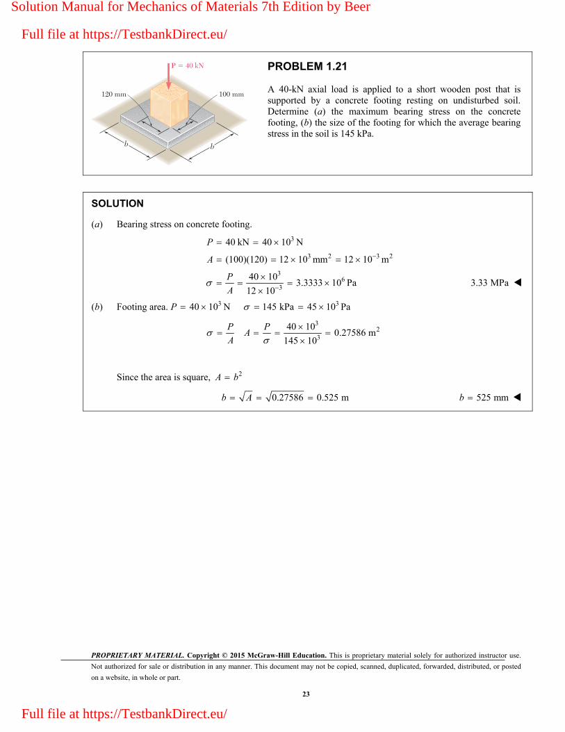
P 5 40 kN
b b
120 mm 100 mm
PROBLEM 1.21
A 40-kN axial load is applied to a short wooden post that is supported by a concrete footing resting on undisturbed soil. Determine (a) the maximum bearing stress on the concrete footing, (b) the size of the footing for which the average bearing stress in the soil is 145 kPa.
SOLUTION
(a) Bearing stress on concrete footing.
3
3 2 3 2
36
3
40 kN 40 10 N
(100)(120) 12 10 mm 12 10 m
40 103.3333 10 Pa
12 10
P
A
P
A 3.33 MPa
(b) Footing area. 3 340 10 N 145 kPa 45 10 Pa P
3
23
40 100.27586 m
145 10
P PA
A
Since the area is square, 2A b
0.27586 0.525 m b A 525 mmb
Solution Manual for Mechanics of Materials 7th Edition by Beer
Full file at https://TestbankDirect.eu/
Full file at https://TestbankDirect.eu/

PROPRIETARY MATERIAL. Copyright © 2015 McGraw-Hill Education. This is proprietary material solely for authorized instructor use.
Not authorized for sale or distribution in any manner. This document may not be copied, scanned, duplicated, forwarded, distributed, or posted
on a website, in whole or part.
24
a aP
PROBLEM 1.22
An axial load P is supported by a short W8 40 column of cross-sectional area 211.7 inA and is distributed to a concrete foundation by a square plate as shown. Knowing that the average normal stress in the column must not exceed 30 ksi and that the bearing stress on the concrete foundation must not exceed 3.0 ksi, determine the side a of the plate that will provide the most economical and safe design.
SOLUTION
For the column, P
A or
(30)(11.7) 351 kips P A
For the a a plate, 3.0 ksi
2351117 in
3.0
PA
Since the plate is square, 2A a
117 a A 10.82 in.a
Solution Manual for Mechanics of Materials 7th Edition by Beer
Full file at https://TestbankDirect.eu/
Full file at https://TestbankDirect.eu/

PROPRIETARY MATERIAL. Copyright © 2015 McGraw-Hill Education. This is proprietary material solely for authorized instructor use.
Not authorized for sale or distribution in any manner. This document may not be copied, scanned, duplicated, forwarded, distributed, or posted
on a website, in whole or part.
25
bd
t
B
A
d
PROBLEM 1.23
Link AB, of width b = 2 in. and thickness t = 14
in., is used to support the end of a horizontal beam. Knowing that the average normal stress in the link is 20 ksi and that the average shearing stress in each of the two pins is 12 ksi, determine (a) the diameter d of the pins, (b) the average bearing stress in the link.
SOLUTION
Rod AB is in compression.
1where 2 in. and in.
4
1( 20)(2) 10 kips
4
A bt b t
P A
Pin: PP
P
A
and 2
4PA d
(a) 4 4 (4)(10)
1.03006 in.(12)
P
P
A Pd
1.030 in.d
(b) 10
38.833 ksi(1.03006)(0.25)b
P
dt
38.8 ksib
Solution Manual for Mechanics of Materials 7th Edition by Beer
Full file at https://TestbankDirect.eu/
Full file at https://TestbankDirect.eu/

PROPRIETARY MATERIAL. Copyright © 2015 McGraw-Hill Education. This is proprietary material solely for authorized instructor use.
Not authorized for sale or distribution in any manner. This document may not be copied, scanned, duplicated, forwarded, distributed, or posted
on a website, in whole or part.
26
16 mm
750 mm
750 mm
12 mm
50 mm B
A
C
P
�
PROBLEM 1.24
Determine the largest load P which may be applied at A when 60°, knowing that the average shearing stress in the 10-mm-diameter pin at B must not exceed 120 MPa and that the average bearing stress in member AB and in the bracket at B must not exceed 90 MPa.
SOLUTION
Geometry: Triangle ABC is an isoseles triangle with angles shown here.
Use joint A as a free body.
Law of sines applied to force triangle:
sin 30 sin 120 sin 30
sin 300.57735
sin 120
sin 30
sin 30
AB AC
ABAB
ACAC
P F F
FP F
FP F
Solution Manual for Mechanics of Materials 7th Edition by Beer
Full file at https://TestbankDirect.eu/
Full file at https://TestbankDirect.eu/
PROPRIETARY MATERIAL. Copyright © 2015 McGraw-Hill Education. This is proprietary material solely for authorized instructor use.
Not authorized for sale or distribution in any manner. This document may not be copied, scanned, duplicated, forwarded, distributed, or posted
on a website, in whole or part.
27
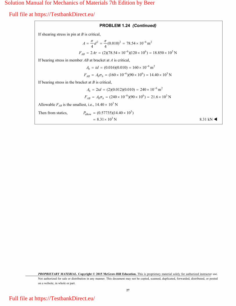
PROBLEM 1.24 (Continued)
If shearing stress in pin at B is critical,
2 2 6 2
6 6 3
(0.010) 78.54 10 m4 4
2 (2)(78.54 10 )(120 10 ) 18.850 10 N
AB
A d
F A
If bearing stress in member AB at bracket at A is critical, 6 2
6 6 3
(0.016)(0.010) 160 10 m
(160 10 )(90 10 ) 14.40 10 N
b
AB b b
A td
F A
If bearing stress in the bracket at B is critical, 6 2
6 6 3
2 (2)(0.012)(0.010) 240 10 m
(240 10 )(90 10 ) 21.6 10 N
b
AB b b
A td
F A
Allowable FAB is the smallest, i.e., 14.40 103 N
Then from statics, 3allow (0.57735)(14.40 10 ) P
38.31 10 N 8.31 kN
Solution Manual for Mechanics of Materials 7th Edition by Beer
Full file at https://TestbankDirect.eu/
Full file at https://TestbankDirect.eu/

PROPRIETARY MATERIAL. Copyright © 2015 McGraw-Hill Education. This is proprietary material solely for authorized instructor use.
Not authorized for sale or distribution in any manner. This document may not be copied, scanned, duplicated, forwarded, distributed, or posted
on a website, in whole or part.
28
16 mm
750 mm
750 mm
12 mm
50 mm B
A
C
P
�
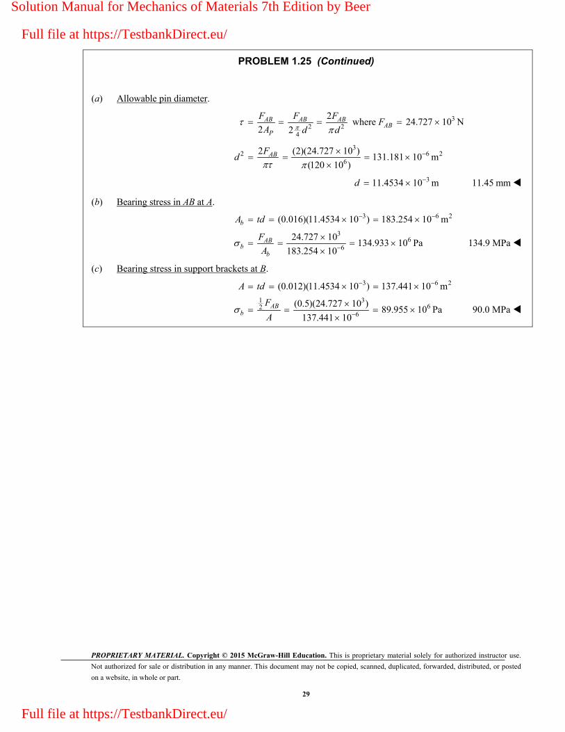
PROBLEM 1.25
Knowing that 40° and P 9 kN, determine (a) the smallest allowable diameter of the pin at B if the average shearing stress in the pin is not to exceed 120 MPa, (b) the corresponding average bearing stress in member AB at B, (c) the corresponding average bearing stress in each of the support brackets at B.
SOLUTION
Geometry: Triangle ABC is an isoseles triangle with angles shown here.
Use joint A as a free body.
Law of sines applied to force triangle:
sin 20 sin110 sin 50sin110
sin 20(9)sin110
24.727 kNsin 20
AB AC
AB
P F F
PF
Solution Manual for Mechanics of Materials 7th Edition by Beer
Full file at https://TestbankDirect.eu/
Full file at https://TestbankDirect.eu/
PROPRIETARY MATERIAL. Copyright © 2015 McGraw-Hill Education. This is proprietary material solely for authorized instructor use.
Not authorized for sale or distribution in any manner. This document may not be copied, scanned, duplicated, forwarded, distributed, or posted
on a website, in whole or part.
29
PROBLEM 1.25 (Continued)
(a) Allowable pin diameter.
2 2
4
2
2 2
AB AB AB
P
F F F
A d d where 324.727 10 N ABF
3
2 6 26
2 (2)(24.727 10 )131.181 10 m
(120 10 )
ABFd
311.4534 10 m d 11.45 mm
(b) Bearing stress in AB at A.
3 6 2
36
6
(0.016)(11.4534 10 ) 183.254 10 m
24.727 10134.933 10 Pa
183.254 10
b
ABb
b
A td
F
A 134.9 MPa
(c) Bearing stress in support brackets at B.
3 6 2
1 362
6
(0.012)(11.4534 10 ) 137.441 10 m
(0.5)(24.727 10 )89.955 10 Pa
137.441 10
AB
b
A td
F
A 90.0 MPa
Solution Manual for Mechanics of Materials 7th Edition by Beer
Full file at https://TestbankDirect.eu/
Full file at https://TestbankDirect.eu/
PROPRIETARY MATERIAL. Copyright © 2015 McGraw-Hill Education. This is proprietary material solely for authorized instructor use.
Not authorized for sale or distribution in any manner. This document may not be copied, scanned, duplicated, forwarded, distributed, or posted
on a website, in whole or part.
30
45 mm
200 mm
100 mm 175 mm
D
F
E
A
CB
P
208u
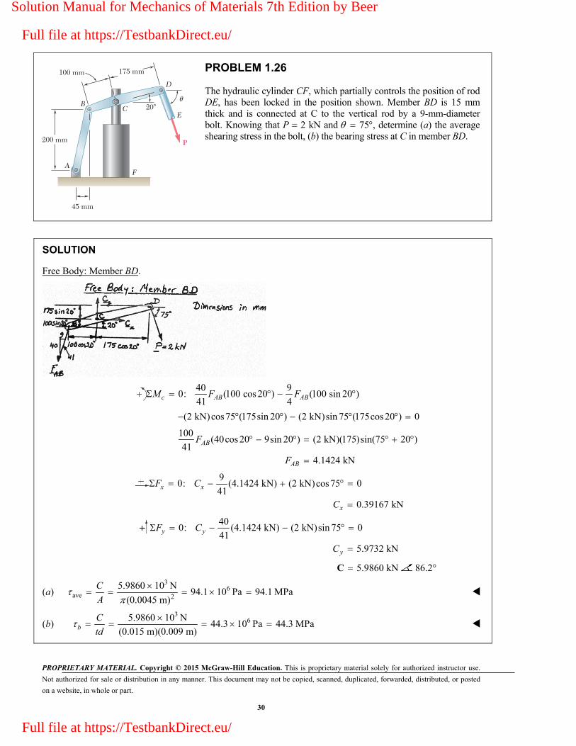
PROBLEM 1.26
The hydraulic cylinder CF, which partially controls the position of rod DE, has been locked in the position shown. Member BD is 15 mm thick and is connected at C to the vertical rod by a 9-mm-diameter bolt. Knowing that P 2 kN and 75 , determine (a) the average shearing stress in the bolt, (b) the bearing stress at C in member BD.
SOLUTION
Free Body: Member BD.
40 9
0: (100 cos 20 ) (100 sin 20 )41 4c AB ABM F F
(2 kN)cos75 (175sin 20 ) (2 kN)sin 75 (175cos 20 ) 0
100
(40cos 20 9sin 20 ) (2 kN)(175)sin(75 20 )41
4.1424 kN
AB
AB
F
F
9
0: (4.1424 kN) (2 kN)cos75 041
0.39167 kN
x x
x
F C
C
40
0: (4.1424 kN) (2 kN)sin 75 041
5.9732 kN
y y
y
F C
C
5.9860 kNC 86.2°
(a) 3
6ave 2
5.9860 10 N94.1 10 Pa 94.1 MPa
(0.0045 m)
C
A
(b) 3
65.9860 10 N44.3 10 Pa 44.3 MPa
(0.015 m)(0.009 m)bC
td
Solution Manual for Mechanics of Materials 7th Edition by Beer
Full file at https://TestbankDirect.eu/
Full file at https://TestbankDirect.eu/

PROPRIETARY MATERIAL. Copyright © 2015 McGraw-Hill Education. This is proprietary material solely for authorized instructor use.
Not authorized for sale or distribution in any manner. This document may not be copied, scanned, duplicated, forwarded, distributed, or posted
on a website, in whole or part.
31
0.2 m0.25 m
0.4 m
20 kN
C
B
AD
E
PROBLEM 1.27
For the assembly and loading of Prob. 1.7, determine (a) the average shearing stress in the pin at B, (b) the average bearing stress at B in member BD, (c) the average bearing stress at B in member ABC, knowing that this member has a 10 50-mm uniform rectangular cross section.
PROBLEM 1.7 Each of the four vertical links has an 8 36-mm uniform rectangular cross section and each of the four pins has a 16-mm diameter. Determine the maximum value of the average normal stress in the links connecting (a) points B and D, (b) points C and E.
SOLUTION
Use bar ABC as a free body.
3
3
0 : (0.040) (0.025 0.040)(20 10 ) 0
32.5 10 N
C BD
BD
M F
F
(a) Shear pin at B. 2
BDF
A for double shear
where 2 2 6 2(0.016) 201.06 10 m4 4
A d
3
66
32.5 1080.822 10 Pa
(2)(201.06 10 )
80.8 MPa
(b) Bearing: link BD. 6 2(0.016)(0.008) 128 10 m A dt
1 3
626
(0.5)(32.5 10 )126.95 10 Pa
128 10BD
b
F
A
127.0 MPa b
(c) Bearing in ABC at B. 6 2(0.016)(0.010) 160 10 m A dt
3
66
32.5 10203.12 10 Pa
160 10BD
bF
A
203 MPa b
Solution Manual for Mechanics of Materials 7th Edition by Beer
Full file at https://TestbankDirect.eu/
Full file at https://TestbankDirect.eu/
PROPRIETARY MATERIAL. Copyright © 2015 McGraw-Hill Education. This is proprietary material solely for authorized instructor use.
Not authorized for sale or distribution in any manner. This document may not be copied, scanned, duplicated, forwarded, distributed, or posted
on a website, in whole or part.
32
A
C
D E
B
12 in.
12 in.
15 in.
16 in. 16 in. 20 in.
1500 lb
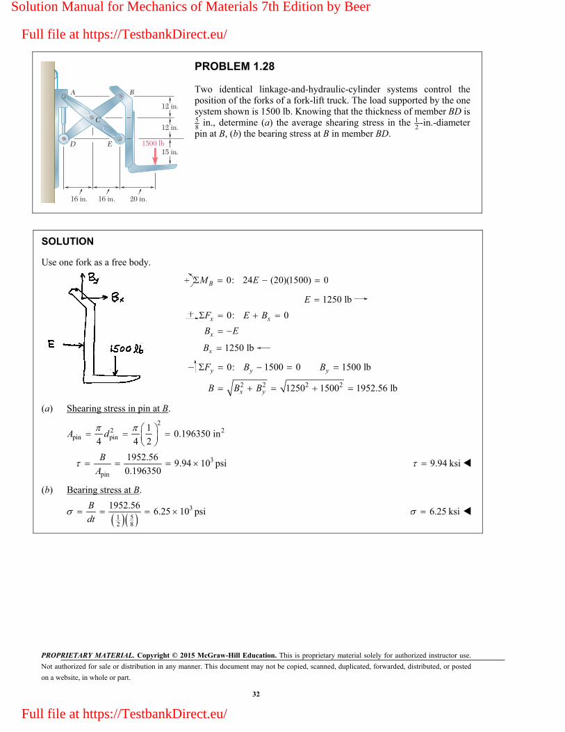
PROBLEM 1.28
Two identical linkage-and-hydraulic-cylinder systems control the position of the forks of a fork-lift truck. The load supported by the one system shown is 1500 lb. Knowing that the thickness of member BD is 58 in., determine (a) the average shearing stress in the 1
2-in.-diameter
pin at B, (b) the bearing stress at B in member BD.
SOLUTION
Use one fork as a free body.
0: 24 (20)(1500) 0BM E
1250 lbE
0: 0x x
x
F E B
B E
1250 lbxB
2 2 2 2
0: 1500 0 1500 lb
1250 1500 1952.56 lb
y y y
x y
F B B
B B B
(a) Shearing stress in pin at B.
2
2 2pin pin
10.196350 in
4 4 2A d
3
pin
1952.569.94 10 psi
0.196350
B
A 9.94 ksi
(b) Bearing stress at B.
351
2 8
1952.566.25 10 psi
B
dt 6.25 ksi
Solution Manual for Mechanics of Materials 7th Edition by Beer
Full file at https://TestbankDirect.eu/
Full file at https://TestbankDirect.eu/

PROPRIETARY MATERIAL. Copyright © 2015 McGraw-Hill Education. This is proprietary material solely for authorized instructor use.
Not authorized for sale or distribution in any manner. This document may not be copied, scanned, duplicated, forwarded, distributed, or posted
on a website, in whole or part.
33
75 mm
150 mm
45454545454545454545454545454545454545454545454545�������������
P'
P
PROBLEM 1.29
Two wooden members of uniform rectangular cross section are joined by the simple glued scarf splice shown. Knowing that P 11 kN, determine the normal and shearing stresses in the glued splice.
SOLUTION
3
3 2 3 20
2 3 23
30
90 45 45
11 kN 11 10 N
(150)(75) 11.25 10 mm 11.25 10 m
cos (11 10 )cos 45489 10 Pa
11.25 10
P
A
P
A 489 kPa
3
33
0
sin 2 (11 10 )(sin 90 )489 10 Pa
2 (2)(11.25 10 )
P
A 489 kPa
Solution Manual for Mechanics of Materials 7th Edition by Beer
Full file at https://TestbankDirect.eu/
Full file at https://TestbankDirect.eu/

PROPRIETARY MATERIAL. Copyright © 2015 McGraw-Hill Education. This is proprietary material solely for authorized instructor use.
Not authorized for sale or distribution in any manner. This document may not be copied, scanned, duplicated, forwarded, distributed, or posted
on a website, in whole or part.
34
75 mm
150 mm
45454545454545454545454545454545454545454545454545�������������
P'
P
PROBLEM 1.30
Two wooden members of uniform rectangular cross section are joined by the simple glued scarf splice shown. Knowing that the maximum allowable shearing stress in the glued splice is 620 kPa, determine (a) the largest load P that can be safely applied, (b) the corresponding tensile stress in the splice.
SOLUTION
3 2 3 20
3
0
90 45 45
(150)(75) 11.25 10 mm 11.25 10 m
620 kPa 620 10 Pa
sin 2
2
A
P
A
(a) 3 3
02 (2)(11.25 10 )(620 10 )
sin2 sin 90
A
P
313.95 10 N 13.95 kNP
(b) 2 3 2
30
cos (13.95 10 )(cos 45 )
11.25 10
P
A
3620 10 Pa 620 kPa
Solution Manual for Mechanics of Materials 7th Edition by Beer
Full file at https://TestbankDirect.eu/
Full file at https://TestbankDirect.eu/
PROPRIETARY MATERIAL. Copyright © 2015 McGraw-Hill Education. This is proprietary material solely for authorized instructor use.
Not authorized for sale or distribution in any manner. This document may not be copied, scanned, duplicated, forwarded, distributed, or posted
on a website, in whole or part.
35
608
5.0 in.3.0 in.
P'
P
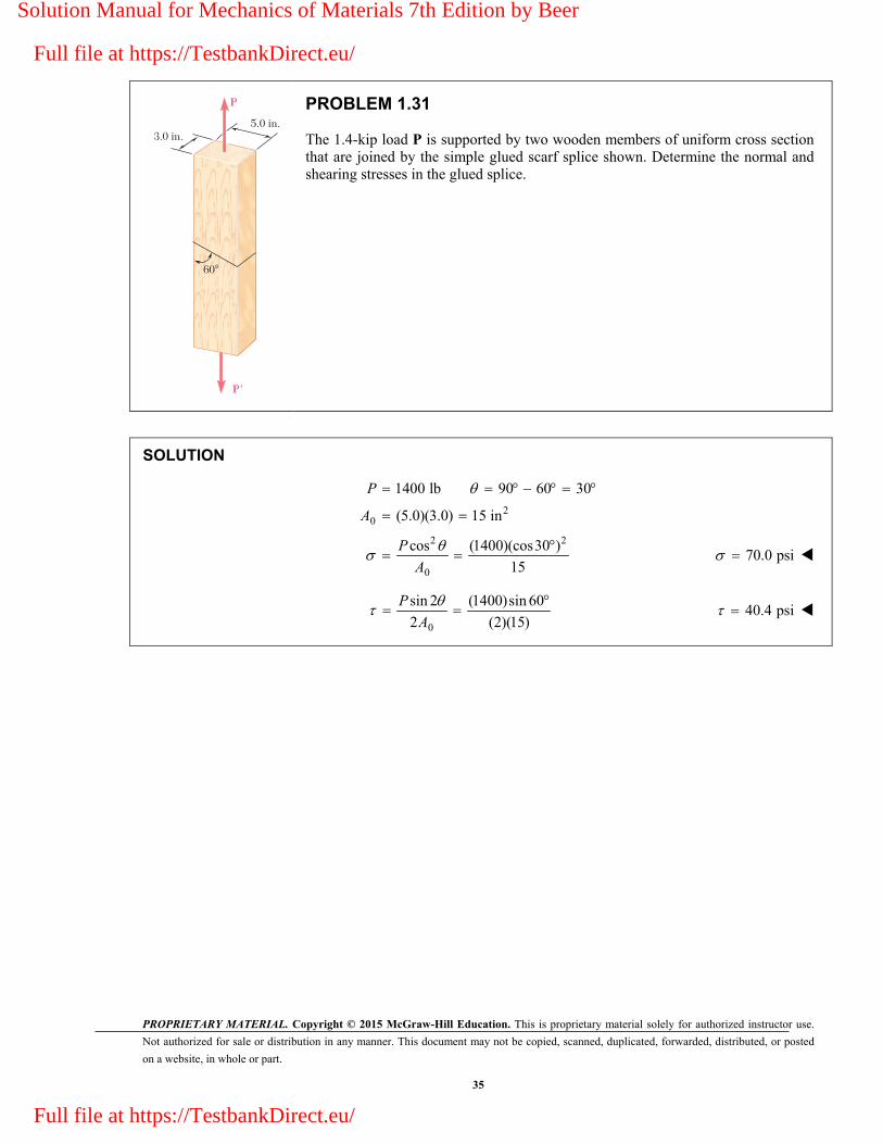
PROBLEM 1.31
The 1.4-kip load P is supported by two wooden members of uniform cross section that are joined by the simple glued scarf splice shown. Determine the normal and shearing stresses in the glued splice.
SOLUTION
20
2 2
0
1400 lb 90 60 30
(5.0)(3.0) 15 in
cos (1400)(cos30 )
15
P
A
P
A
70.0 psi
0
sin 2 (1400)sin 60
2 (2)(15)
P
A 40.4 psi
Solution Manual for Mechanics of Materials 7th Edition by Beer
Full file at https://TestbankDirect.eu/
Full file at https://TestbankDirect.eu/
PROPRIETARY MATERIAL. Copyright © 2015 McGraw-Hill Education. This is proprietary material solely for authorized instructor use.
Not authorized for sale or distribution in any manner. This document may not be copied, scanned, duplicated, forwarded, distributed, or posted
on a website, in whole or part.
36
608
5.0 3.0 in.
P'
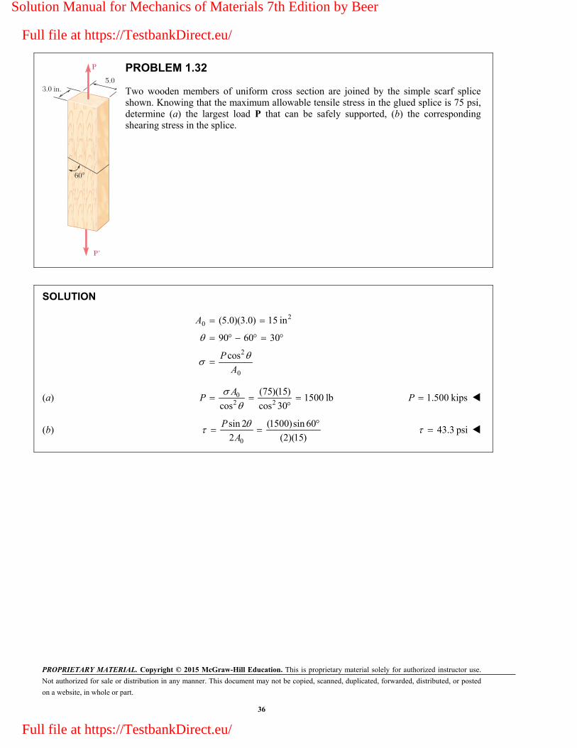
P PROBLEM 1.32
Two wooden members of uniform cross section are joined by the simple scarf splice shown. Knowing that the maximum allowable tensile stress in the glued splice is 75 psi, determine (a) the largest load P that can be safely supported, (b) the corresponding shearing stress in the splice.
SOLUTION
20
2
0
(5.0)(3.0) 15 in
90 60 30
cos
A
P
A
(a) 02 2
(75)(15)1500 lb
cos cos 30
AP 1.500 kipsP
(b) 0
sin 2 (1500)sin 60
2 (2)(15)
P
A 43.3 psi
Solution Manual for Mechanics of Materials 7th Edition by Beer
Full file at https://TestbankDirect.eu/
Full file at https://TestbankDirect.eu/

PROPRIETARY MATERIAL. Copyright © 2015 McGraw-Hill Education. This is proprietary material solely for authorized instructor use.
Not authorized for sale or distribution in any manner. This document may not be copied, scanned, duplicated, forwarded, distributed, or posted
on a website, in whole or part.
37
6 in.
6 in.
P
PROBLEM 1.33
A centric load P is applied to the granite block shown. Knowing that the resulting maximum value of the shearing stress in the block is 2.5 ksi, determine (a) the magnitude of P, (b) the orientation of the surface on which the maximum shearing stress occurs, (c) the normal stress exerted on that surface, (d ) the maximum value of the normal stress in the block.
SOLUTION
20
max
max
(6)(6) 36 in
2.5 ksi
45 for plane of
A
(a) max 0 max0
| || | 2 (2)(36)(2.5)
2
PP A
A 180.0 kipsP
(b) sin 2 1 2 90 45.0
(c) 245
0 0
180cos 45
2 (2)(36)
P P
A A 45 2.50 ksi
(d ) max0
180
36
P
A
max 5.00 ksi
Solution Manual for Mechanics of Materials 7th Edition by Beer
Full file at https://TestbankDirect.eu/
Full file at https://TestbankDirect.eu/

PROPRIETARY MATERIAL. Copyright © 2015 McGraw-Hill Education. This is proprietary material solely for authorized instructor use.
Not authorized for sale or distribution in any manner. This document may not be copied, scanned, duplicated, forwarded, distributed, or posted
on a website, in whole or part.
38
6 in.
6 in.
P
PROBLEM 1.34
A 240-kip load P is applied to the granite block shown. Determine the resulting maximum value of (a) the normal stress, (b) the shearing stress. Specify the orientation of the plane on which each of these maximum values occurs.
SOLUTION
20
2 2 2
0
(6)(6) 36 in
240cos cos 6.67cos
36
A
P
A
(a) max tensile stress 0 at 90.0 max. compressive stress 6.67 ksi at 0
(b) max0
240
2 (2)(36)
P
A
max 3.33 ksi at 45
Solution Manual for Mechanics of Materials 7th Edition by Beer
Full file at https://TestbankDirect.eu/
Full file at https://TestbankDirect.eu/

PROPRIETARY MATERIAL. Copyright © 2015 McGraw-Hill Education. This is proprietary material solely for authorized instructor use.
Not authorized for sale or distribution in any manner. This document may not be copied, scanned, duplicated, forwarded, distributed, or posted
on a website, in whole or part.
39
208
P
Weld
10 mm
PROBLEM 1.35
A steel pipe of 400-mm outer diameter is fabricated from 10-mm thick plate by welding along a helix that forms an angle of 20 with a plane perpendicular to the axis of the pipe. Knowing that a 300-kN axial force P is applied to the pipe, determine the normal and shearing stresses in directions respectively normal and tangential to the weld.
SOLUTION
2 2 2 2
3 2
3 22 6
3
0.400 m
10.200 m
20.200 0.010 0.190 m
( ) (0.200 0.190 )
12.2522 10 m
20
300 10 cos 20cos 21.621 10 Pa
12.2522 10
o
o o
i o
o o i
o
d
r d
r r t
A r r
P
A 21.6 MPa
3
63
0
300 10 sin 40sin 2 7.8695 10 Pa
2 (2)(12.2522 10 )
P
A 7.87 MPa
Solution Manual for Mechanics of Materials 7th Edition by Beer
Full file at https://TestbankDirect.eu/
Full file at https://TestbankDirect.eu/

PROPRIETARY MATERIAL. Copyright © 2015 McGraw-Hill Education. This is proprietary material solely for authorized instructor use.
Not authorized for sale or distribution in any manner. This document may not be copied, scanned, duplicated, forwarded, distributed, or posted
on a website, in whole or part.
40
208
P
Weld
10 mm
PROBLEM 1.36
A steel pipe of 400-mm outer diameter is fabricated from 10-mm thick plate by welding along a helix that forms an angle of 20° with a plane perpendicular to the axis of the pipe. Knowing that the maximum allowable normal and shearing stresses in the directions respectively normal and tangential to the weld are 60 MPa and
36 MPa, determine the magnitude P of the largest axial force that can be applied to the pipe.
SOLUTION
2 2 2 2
3 2
0.400 m
10.200 m
20.200 0.010 0.190 m
( ) (0.200 0.190 )
12.2522 10 m
20
o
o o
i o
o o i
d
r d
r r t
A r r
Based on 2
0
| | 60 MPa: cosP
A
3 6
32 2
(12.2522 10 )(60 10 )832.52 10 N
cos cos 20
oA
P
Based on | | 30 MPa: sin 22
o
P
A
3 6
32 (2)(12.2522 10 )(36 10 )1372.39 10 N
sin 2 sin 40
oA
P
Smaller value is the allowable value of P. 833 kNP
Solution Manual for Mechanics of Materials 7th Edition by Beer
Full file at https://TestbankDirect.eu/
Full file at https://TestbankDirect.eu/

PROPRIETARY MATERIAL. Copyright © 2015 McGraw-Hill Education. This is proprietary material solely for authorized instructor use.
Not authorized for sale or distribution in any manner. This document may not be copied, scanned, duplicated, forwarded, distributed, or posted
on a website, in whole or part.
41
12 in.
9 in. 1 in.
C
D
Q
A
9 in.
12 in.
F
Q'
BE
in.12
in.38
PROBLEM 1.37
A steel loop ABCD of length 5 ft and of 38
-in. diameter is placed as shown around a 1-in.-diameter aluminum rod AC. Cables BE and DF, each of 1
2-in. diameter, are used to apply the load Q. Knowing that the
ultimate strength of the steel used for the loop and the cables is 70 ksi, and that the ultimate strength of the aluminum used for the rod is 38 ksi, determine the largest load Q that can be applied if an overall factor of safety of 3 is desired.
SOLUTION
Using joint B as a free body and considering symmetry,
3 6
2 05 5
AB ABF Q Q F
Using joint A as a free body and considering symmetry,
42 0
58 5 3
05 6 4
AB AC
AC AC
F F
Q F Q F
Based on strength of cable BE,
2
2 1(70) 13.7445 kips
4 4 2U U UQ A d
Based on strength of steel loop,
2,
2
6 6 6
5 5 5 4
6 3(70) 9.2775 kips
5 4 8
U AB U U UQ F A d
Based on strength of rod AC,
2 2,
3 3 3 3(38) (1.0) 22.384 kips
4 4 4 4 4 4U AC U U UQ F A d
Actual ultimate load QU is the smallest, 9.2775 kipsUQ
Allowable load: 9.2775
3.0925 kips. . 3UQ
QF S
3.09 kipsQ
Solution Manual for Mechanics of Materials 7th Edition by Beer
Full file at https://TestbankDirect.eu/
Full file at https://TestbankDirect.eu/

PROPRIETARY MATERIAL. Copyright © 2015 McGraw-Hill Education. This is proprietary material solely for authorized instructor use.
Not authorized for sale or distribution in any manner. This document may not be copied, scanned, duplicated, forwarded, distributed, or posted
on a website, in whole or part.
42
A B
CD
480 mm
908
w
P
PROBLEM 1.38
Link BC is 6 mm thick, has a width w 25 mm, and is made of a steel with a 480-MPa ultimate strength in tension. What was the safety factor used if the structure shown was designed to support a 16-kN load P?
SOLUTION
Use bar ACD as a free body and note that member BC is a two-force member.
3
3
0:
(480) (600) 0
600 (600)(16 10 )20 10 N
480 480
A
BC
BC
M
F P
F P
Ultimate load for member BC: U UF A
6 3(480 10 )(0.006)(0.025) 72 10 N UF
Factor of safety: 3
3
72 10F.S.
20 10
U
BC
F
F F.S. 3.60
Solution Manual for Mechanics of Materials 7th Edition by Beer
Full file at https://TestbankDirect.eu/
Full file at https://TestbankDirect.eu/

PROPRIETARY MATERIAL. Copyright © 2015 McGraw-Hill Education. This is proprietary material solely for authorized instructor use.
Not authorized for sale or distribution in any manner. This document may not be copied, scanned, duplicated, forwarded, distributed, or posted
on a website, in whole or part.
43
A B
CD
480 mm
908
w
P
PROBLEM 1.39
Link BC is 6 mm thick and is made of a steel with a 450-MPa ultimate strength in tension. What should be its width w if the structure shown is being designed to support a 20-kN load P with a factor of safety of 3?
SOLUTION
Use bar ACD as a free body and note that member BC is a two-force member.
3
3
0:
(480) 600 0
600 (600)(20 10 )25 10 N
480 480
A
BC
BC
M
F P
PF
For a factor of safety F.S. 3, the ultimate load of member BC is
3 3(F.S.)( ) (3)(25 10 ) 75 10 N U BCF F
But U UF A 3
6 26
75 10166.667 10 m
450 10
U
U
FA
For a rectangular section, A wt or 6
3166.667 1027.778 10 m
0.006
Aw
t
27.8 mmw
Solution Manual for Mechanics of Materials 7th Edition by Beer
Full file at https://TestbankDirect.eu/
Full file at https://TestbankDirect.eu/

PROPRIETARY MATERIAL. Copyright © 2015 McGraw-Hill Education. This is proprietary material solely for authorized instructor use.
Not authorized for sale or distribution in any manner. This document may not be copied, scanned, duplicated, forwarded, distributed, or posted
on a website, in whole or part.
44
1.4 m
0.75 m
0.4 m
B
A
C
PROBLEM 1.40
Members AB and BC of the truss shown are made of the same alloy. It is known that a 20-mm-square bar of the same alloy was tested to failure and that an ultimate load of 120 kN was recorded. If a factor of safety of 3.2 is to be achieved for both bars, determine the required cross-sectional area of (a) bar AB, (b) bar AC.
SOLUTION
Length of member AB:
2 20.75 0.4 0.85 m AB
Use entire truss as a free body.
0: 1.4 (0.75)(28) 0
15 kN
c x
x
M A
A
0: 28 0
28 kN
y y
y
F A
A
Use Joint A as free body.
0.750: 0
0.85(0.85)(15)
17 kN0.75
x AB x
AB
F F A
F
0.40: 0
0.85(0.4)(17)
28 20 kN0.85
y y AC AB
AC
F A F F
F
For the test bar, 2 6 2 3(0.020) 400 10 m 120 10 NUA P
For the material, 3
66
120 10300 10 Pa
400 10U
UP
A
Solution Manual for Mechanics of Materials 7th Edition by Beer
Full file at https://TestbankDirect.eu/
Full file at https://TestbankDirect.eu/

PROPRIETARY MATERIAL. Copyright © 2015 McGraw-Hill Education. This is proprietary material solely for authorized instructor use.
Not authorized for sale or distribution in any manner. This document may not be copied, scanned, duplicated, forwarded, distributed, or posted
on a website, in whole or part.
45
PROBLEM 1.40 (Continued)
(a) For member AB: F.S. U U AB
AB AB
P A
F F
3
6 26
(F.S.) (3.2)(17 10 )181.333 10 m
300 10AB
ABU
FA
2181.3 mmABA
(b) For member AC: F.S. U U AC
AC AC
P A
F F
3
6 26
(F.S.) (3.2)(20 10 )213.33 10 m
300 10AC
ACU
FA
2213 mmACA
Solution Manual for Mechanics of Materials 7th Edition by Beer
Full file at https://TestbankDirect.eu/
Full file at https://TestbankDirect.eu/

PROPRIETARY MATERIAL. Copyright © 2015 McGraw-Hill Education. This is proprietary material solely for authorized instructor use.
Not authorized for sale or distribution in any manner. This document may not be copied, scanned, duplicated, forwarded, distributed, or posted
on a website, in whole or part.
46
1.4 m
0.75 m
0.4 m
B
A
C
PROBLEM 1.41
Members AB and BC of the truss shown are made of the same alloy. It is known that a 20-mm-square bar of the same alloy was tested to failure and that an ultimate load of 120 kN was recorded. If bar AB has a cross-sectional area of 225 mm2, determine (a) the factor of safety for bar AB and (b) the cross-sectional area of bar AC if it is to have the same factor of safety as bar AB.
SOLUTION
Length of member AB:
2 20.75 0.4 0.85 m AB
Use entire truss as a free body.
0: 1.4 (0.75)(28) 0
15 kN
c x
x
M A
A
0: 28 0
28 kN
y y
y
F A
A
Use Joint A as free body.
0.750: 0
0.85(0.85)(15)
17 kN0.75
x AB x
AB
F F A
F
0.40: 0
0.85(0.4)(17)
28 20 kN0.85
y y AC AB
AC
F A F F
F
For the test bar, 2 6 2 3(0.020) 400 10 m 120 10 NUA P
For the material, 3
66
120 10300 10 Pa
400 10U
UP
A
Solution Manual for Mechanics of Materials 7th Edition by Beer
Full file at https://TestbankDirect.eu/
Full file at https://TestbankDirect.eu/
PROPRIETARY MATERIAL. Copyright © 2015 McGraw-Hill Education. This is proprietary material solely for authorized instructor use.
Not authorized for sale or distribution in any manner. This document may not be copied, scanned, duplicated, forwarded, distributed, or posted
on a website, in whole or part.
47
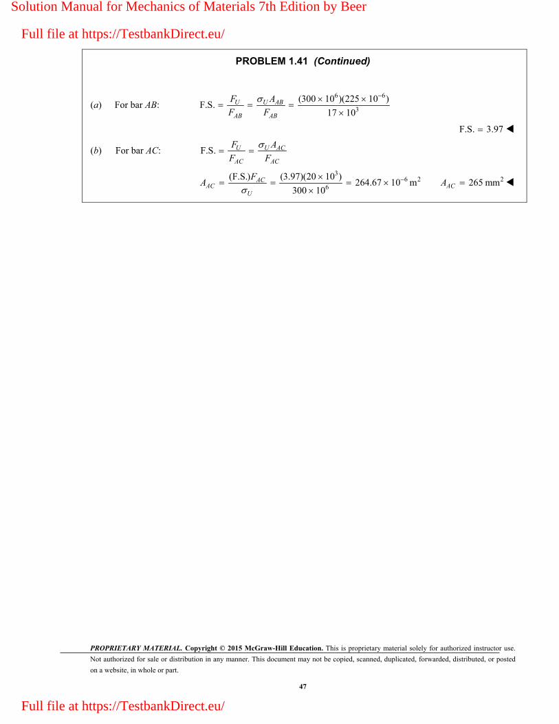
PROBLEM 1.41 (Continued)
(a) For bar AB: 6 6
3
(300 10 )(225 10 )F.S.
17 10U U AB
AB AB
F A
F F
F.S. 3.97
(b) For bar AC: F.S. U U AC
AC AC
F A
F F
3
6 26
(F.S.) (3.97)(20 10 )264.67 10 m
300 10AC
ACU
FA
2265 mmACA
Solution Manual for Mechanics of Materials 7th Edition by Beer
Full file at https://TestbankDirect.eu/
Full file at https://TestbankDirect.eu/
PROPRIETARY MATERIAL. Copyright © 2015 McGraw-Hill Education. This is proprietary material solely for authorized instructor use.
Not authorized for sale or distribution in any manner. This document may not be copied, scanned, duplicated, forwarded, distributed, or posted
on a website, in whole or part.
48
1.4 ft
35�
B
A
C DE
1.4 ft 1.4 ft
600 lb/ft
5 kips
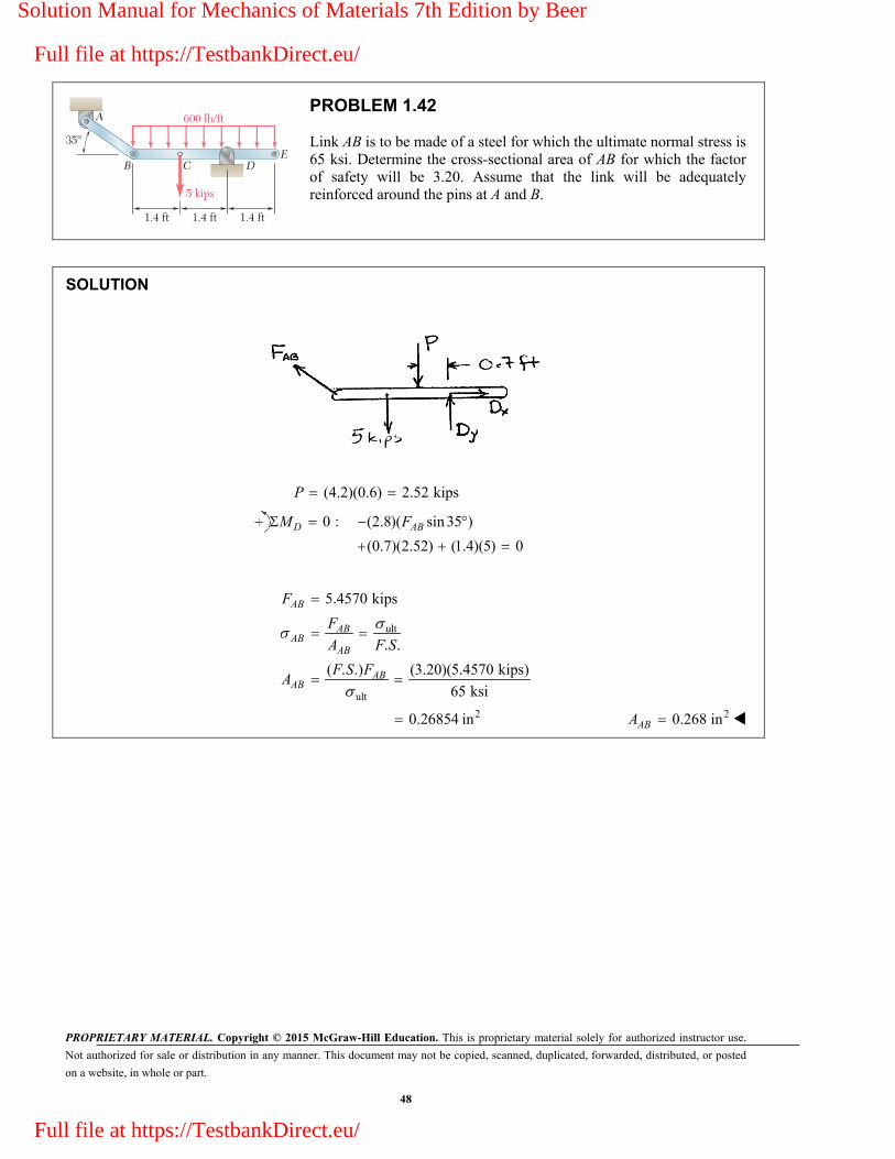
PROBLEM 1.42
Link AB is to be made of a steel for which the ultimate normal stress is 65 ksi. Determine the cross-sectional area of AB for which the factor of safety will be 3.20. Assume that the link will be adequately reinforced around the pins at A and B.
SOLUTION
(4.2)(0.6) 2.52 kipsP
0 : (2.8)( sin 35 )
(0.7)(2.52) (1.4)(5) 0D ABM F
ult
ult
2
5.4570 kips
. .
( . .) (3.20)(5.4570 kips)
65 ksi
0.26854 in
AB
ABAB
AB
ABAB
F
F
A F S
F S FA
20.268 inABA
Solution Manual for Mechanics of Materials 7th Edition by Beer
Full file at https://TestbankDirect.eu/
Full file at https://TestbankDirect.eu/

PROPRIETARY MATERIAL. Copyright © 2015 McGraw-Hill Education. This is proprietary material solely for authorized instructor use.
Not authorized for sale or distribution in any manner. This document may not be copied, scanned, duplicated, forwarded, distributed, or posted
on a website, in whole or part.
49
16 kN
L
125 mm
6 mm
16 kN
PROBLEM 1.43
Two wooden members are joined by plywood splice plates that are fully glued on the contact surfaces. Knowing that the clearance between the ends of the members is 6 mm and that the ultimate shearing stress in the glued joint is 2.5 MPa, determine the length L for which the factor of safety is 2.75 for the loading shown.
SOLUTION
all2.5 MPa
0.90909 MPa2.75
On one face of the upper contact surface,
0.006 m
(0.125 m)2
LA
Since there are 2 contact surfaces,
all
36
2
16 100.90909 10
( 0.006)(0.125)
0.14680 m
P
A
L
L
146.8 mm
Solution Manual for Mechanics of Materials 7th Edition by Beer
Full file at https://TestbankDirect.eu/
Full file at https://TestbankDirect.eu/
PROPRIETARY MATERIAL. Copyright © 2015 McGraw-Hill Education. This is proprietary material solely for authorized instructor use.
Not authorized for sale or distribution in any manner. This document may not be copied, scanned, duplicated, forwarded, distributed, or posted
on a website, in whole or part.
50
16 kN
L
125 mm
6 mm
16 kN
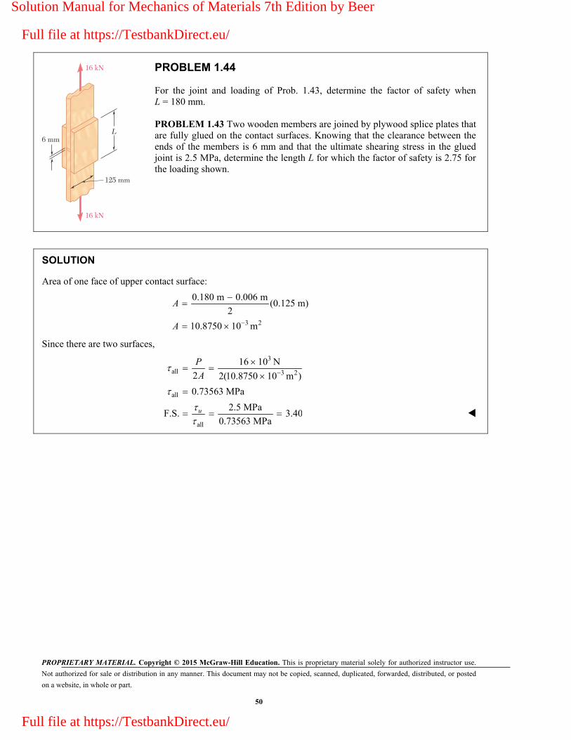
PROBLEM 1.44
For the joint and loading of Prob. 1.43, determine the factor of safety when L = 180 mm.
PROBLEM 1.43 Two wooden members are joined by plywood splice plates that are fully glued on the contact surfaces. Knowing that the clearance between the ends of the members is 6 mm and that the ultimate shearing stress in the glued joint is 2.5 MPa, determine the length L for which the factor of safety is 2.75 for the loading shown.
SOLUTION
Area of one face of upper contact surface:
3 2
0.180 m 0.006 m(0.125 m)
2
10.8750 10 m
A
A
Since there are two surfaces,
3
all 3 2
all
all
16 10 N
2 2(10.8750 10 m )
0.73563 MPa
2.5 MPaF.S. 3.40
0.73563 MPau
P
A
Solution Manual for Mechanics of Materials 7th Edition by Beer
Full file at https://TestbankDirect.eu/
Full file at https://TestbankDirect.eu/

PROPRIETARY MATERIAL. Copyright © 2015 McGraw-Hill Education. This is proprietary material solely for authorized instructor use.
Not authorized for sale or distribution in any manner. This document may not be copied, scanned, duplicated, forwarded, distributed, or posted
on a website, in whole or part.
51
P
PROBLEM 1.45
Three 34
-in.-diameter steel bolts are to be used to attach the steel plate shown to a wooden beam. Knowing that the plate will support a load P = 24 kips and that the ultimate shearing stress for the steel used is 52 ksi, determine the factor of safety for this design.
SOLUTION
For each bolt, 2
2 230.44179 in
4 4 4A d
(0.44179)(52)
22.973 kipsU UP A
For the three bolts, (3)(22.973) 68.919 kipsUP
Factor of safety:
68.919
. .24
UPF S
P . . 2.87F S
Solution Manual for Mechanics of Materials 7th Edition by Beer
Full file at https://TestbankDirect.eu/
Full file at https://TestbankDirect.eu/

PROPRIETARY MATERIAL. Copyright © 2015 McGraw-Hill Education. This is proprietary material solely for authorized instructor use.
Not authorized for sale or distribution in any manner. This document may not be copied, scanned, duplicated, forwarded, distributed, or posted
on a website, in whole or part.
52
P
PROBLEM 1.46
Three steel bolts are to be used to attach the steel plate shown to a wooden beam. Knowing that the plate will support a load P = 28 kips, that the ultimate shearing stress for the steel used is 52 ksi, and that a factor of safety of 3.25 is desired, determine the required diameter of the bolts.
SOLUTION
For each bolt, 24
8 kips3
P
Required: ( . .) (3.25)(8.0) 26.0 kipsUP F S P
2 24
4
4 (4)(26.0)0.79789 in.
(52)
U U UU
U
U
P P P
A d d
Pd
0.798 in.d
Solution Manual for Mechanics of Materials 7th Edition by Beer
Full file at https://TestbankDirect.eu/
Full file at https://TestbankDirect.eu/

PROPRIETARY MATERIAL. Copyright © 2015 McGraw-Hill Education. This is proprietary material solely for authorized instructor use.
Not authorized for sale or distribution in any manner. This document may not be copied, scanned, duplicated, forwarded, distributed, or posted
on a website, in whole or part.
53
12
40 mm
d
c
b
P
12 P
PROBLEM 1.47
A load P is supported as shown by a steel pin that has been inserted in a short wooden member hanging from the ceiling. The ultimate strength of the wood used is 60 MPa in tension and 7.5 MPa in shear, while the ultimate strength of the steel is 145 MPa in shear. Knowing that
40 mm,b 55 mm,c and 12 mm,d determine the load P if an overall factor of safety of 3.2 is desired.
SOLUTION
Based on double shear in pin,
2
2 6 3
2 24
(2)(0.012) (145 10 ) 32.80 10 N4
U U UP A d
Based on tension in wood,
6
3
( )
(0.040)(0.040 0.012)(60 10 )
67.2 10 N
U U UP A w b d
Based on double shear in the wood,
6
3
2 2 (2)(0.040)(0.055)(7.5 10 )
33.0 10 N
U U UP A wc
Use smallest 332.8 10 N UP
Allowable: 3
332.8 1010.25 10 N
. . 3.2
UP
PF S
10.25 kN
Solution Manual for Mechanics of Materials 7th Edition by Beer
Full file at https://TestbankDirect.eu/
Full file at https://TestbankDirect.eu/

PROPRIETARY MATERIAL. Copyright © 2015 McGraw-Hill Education. This is proprietary material solely for authorized instructor use.
Not authorized for sale or distribution in any manner. This document may not be copied, scanned, duplicated, forwarded, distributed, or posted
on a website, in whole or part.
54
12
40 mm
d
c
b
P
12 P
PROBLEM 1.48
For the support of Prob. 1.47, knowing that the diameter of the pin is 16 mmd and that the magnitude of the load is 20 kN,P determine
(a) the factor of safety for the pin, (b) the required values of b and c if the factor of safety for the wooden members is the same as that found in part a for the pin.
PROBLEM 1.47 A load P is supported as shown by a steel pin that has been inserted in a short wooden member hanging from the ceiling. The ultimate strength of the wood used is 60 MPa in tension and 7.5 MPa in shear, while the ultimate strength of the steel is 145 MPa in shear. Knowing that 40 mm,b 55 mm,c and 12 mm,d determine the load P if an overall factor of safety of 3.2 is desired.
SOLUTION
320 kN 20 10 N P
(a) Pin: 2 2 6 2(0.016) 2.01.06 10 m4 4
A d
Double shear: 2 2
UU
P P
A A
6 6 32 (2)(201.16 10 )(145 10 ) 58.336 10 N U UP A
3
3
58.336 10. .
20 10
UP
F SP . . 2.92F S
(b) Tension in wood: 358.336 10 N for same F.S. UP
where 40 mm 0.040 m( )
U UU
P Pw
A w b d
3
36
58.336 100.016 40.3 10 m
(0.040)(60 10 )
U
U
Pb d
w 40.3 mmb
Shear in wood: 358.336 10 N for same F.S. UP
Double shear: each area is A wc 2 2
U UU
P P
A wc
3
36
58.336 1097.2 10 m
2 (2)(0.040)(7.5 10 )
U
U
Pc
w 97.2 mmc
Solution Manual for Mechanics of Materials 7th Edition by Beer
Full file at https://TestbankDirect.eu/
Full file at https://TestbankDirect.eu/

PROPRIETARY MATERIAL. Copyright © 2015 McGraw-Hill Education. This is proprietary material solely for authorized instructor use.
Not authorized for sale or distribution in any manner. This document may not be copied, scanned, duplicated, forwarded, distributed, or posted
on a website, in whole or part.
55
a
bP
34
in.14
in.
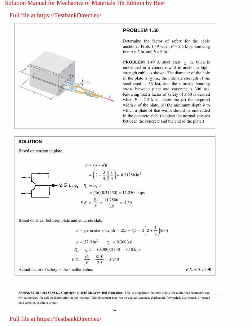
PROBLEM 1.49
A steel plate 14
in. thick is embedded in a concrete wall to anchor a high-strength cable as shown. The diameter of the hole in the plate is 3
4 in., the ultimate strength of the steel used is
36 ksi, and the ultimate bonding stress between plate and concrete is 300 psi. Knowing that a factor of safety of 3.60 is desired when P = 2.5 kips, determine (a) the required width a of the plate, (b) the minimum depth b to which a plate of that width should be embedded in the concrete slab. (Neglect the normal stresses between the concrete and the end of the plate.)
SOLUTION
Based on tension in plate,
( )
( ). .
U U
U U
A a d t
P A
P a d tF S
P P
Solving for a,
14
( . .) 3 (3.60)(2.5)
4 (36)U
F S Pa d
t
(a) 1.750 in.a
Based on shear between plate and concrete slab,
perimeter depth 2( ) 0.300 ksiUA a t b
2 ( ) . . UU U U
PP A a t b F S
P
Solving for b, 14
( . .) (3.6)(2.5)
2( ) (2) 1.75 (0.300)U
F S Pb
a t
(b) 7.50 in.b
Solution Manual for Mechanics of Materials 7th Edition by Beer
Full file at https://TestbankDirect.eu/
Full file at https://TestbankDirect.eu/
PROPRIETARY MATERIAL. Copyright © 2015 McGraw-Hill Education. This is proprietary material solely for authorized instructor use.
Not authorized for sale or distribution in any manner. This document may not be copied, scanned, duplicated, forwarded, distributed, or posted
on a website, in whole or part.
56
a
bP
34
in.14
in.
PROBLEM 1.50
Determine the factor of safety for the cable anchor in Prob. 1.49 when P 2.5 kips, knowing that a 2 in. and b 6 in.
PROBLEM 1.49 A steel plate 14
in. thick is embedded in a concrete wall to anchor a high-strength cable as shown. The diameter of the hole in the plate is 3
4 in., the ultimate strength of the
steel used is 36 ksi, and the ultimate bonding stress between plate and concrete is 300 psi. Knowing that a factor of safety of 3.60 is desired when P = 2.5 kips, determine (a) the required width a of the plate, (b) the minimum depth b to which a plate of that width should be embedded in the concrete slab. (Neglect the normal stresses between the concrete and the end of the plate.)
SOLUTION
Based on tension in plate,
2
( )
3 12 0.31250 in
4 4
A a d t
(36)(0.31250) 11.2500 kips
U UP A
11.2500. . 4.50
3.5UP
F SP
Based on shear between plate and concrete slab,
1
perimeter depth 2( ) 2 2 (6.0)4
A a t b
227.0 in 0.300 ksiUA
(0.300)(27.0) 8.10 kipsU UP A
8.10
. . 3.2402.5
UPF S
P
Actual factor of safety is the smaller value. . . 3.24F S
Solution Manual for Mechanics of Materials 7th Edition by Beer
Full file at https://TestbankDirect.eu/
Full file at https://TestbankDirect.eu/

PROPRIETARY MATERIAL. Copyright © 2015 McGraw-Hill Education. This is proprietary material solely for authorized instructor use.
Not authorized for sale or distribution in any manner. This document may not be copied, scanned, duplicated, forwarded, distributed, or posted
on a website, in whole or part.
57
P6 in.
8 in.
4 in.
12
in.
A
B C D
PROBLEM 1.51
Link AC is made of a steel with a 65-ksi ultimate normal stress and has a 1 1
4 2 -in. uniform rectangular cross section. It is connected to a
support at A and to member BCD at C by 34
-in.-diameter pins, while member BCD is connected to its support at B by a 5
16-in.-diameter pin.
All of the pins are made of a steel with a 25-ksi ultimate shearing stress and are in single shear. Knowing that a factor of safety of 3.25 is desired, determine the largest load P that can be applied at D. Note that link AC is not reinforced around the pin holes.
SOLUTION
Use free body BCD.
8
0 : (6) 10 010B ACM F P
0.48 ACP F (1)
6
0 : 010x x ACF B F
6
1.2510
x ACB F P
0 : 6 4 0 C yM B P
2 2
i.e.3 3y yB P B P
2
2 2 2 21.25 1.41667 0.70588
3
x yB B B P P P B (2)
Shear in pins at A and C.
2
2pin
25 30.84959 kips
. . 4 3.25 4 8U
ACF A dF S
Tension on net section of A and C.
net net65 1 1 3
0.625 kips. . 3.25 4 2 8U
ACF A AF S
Smaller value of FAC is 0.625 kips.
From (1), (0.48)(0.625) 0.300 kipsP
Shear in pin at B. 2
2pin
25 50.58999 kips
. . 4 3.25 4 16UB A d
F S
From (2), (0.70588)(0.58999) 0.416 kipsP
Allowable value of P is the smaller value. 0.300 kipsP or 300 lbP
Solution Manual for Mechanics of Materials 7th Edition by Beer
Full file at https://TestbankDirect.eu/
Full file at https://TestbankDirect.eu/

PROPRIETARY MATERIAL. Copyright © 2015 McGraw-Hill Education. This is proprietary material solely for authorized instructor use.
Not authorized for sale or distribution in any manner. This document may not be copied, scanned, duplicated, forwarded, distributed, or posted
on a website, in whole or part.
58
P6 in.
8 in.
4 in.
12
in.
A
B C D
PROBLEM 1.52
Solve Prob. 1.51, assuming that the structure has been redesigned to use 5
16-in-diameter pins at A and C as well as at B and that no other changes
have been made.
PROBLEM 1.51 Link AC is made of a steel with a 65-ksi ultimate normal stress and has a 1 1
4 2 -in. uniform rectangular cross section. It is
connected to a support at A and to member BCD at C by 34
-in.-diameter pins, while member BCD is connected to its support at B by a 5
16-in.-
diameter pin. All of the pins are made of a steel with a 25-ksi ultimate shearing stress and are in single shear. Knowing that a factor of safety of 3.25 is desired, determine the largest load P that can be applied at D. Note that link AC is not reinforced around the pin holes.
SOLUTION
Use free body BCD.
8
0 : (6) 10 010B ACM F P
0.48 ACP F (1)
6
0 : 010y x ACF B F
6
1.2510
x ACB F P
0 : 6 4 0C yM B P
2 2
i.e.3 3y yB P B P
2
2 2 2 21.25 1.41667 0.70583
3x yB B B P P P B
(2)
Shear in pins at A and C.
2
2pin
25 50.58999 kips
. . 4 3.25 4 16U
ACF A dF S
Tension on net section of A and C.
net net65 1 1 5
0.9375 kips. . 3.25 4 2 16U
ACF A AF S
Smaller value of FAC is 0.58999 kips.
From (1), (0.48)(0.58999) 0.283 kipsP
Shear in pin at B. 2
2pin
25 50.58999 kips
. . 4 3.25 4 16UB A d
F S
From (2), (0.70588)(0.58999) 0.416 kipsP
Allowable value of P is the smaller value. 0.283 kipsP or 283 lbP
Solution Manual for Mechanics of Materials 7th Edition by Beer
Full file at https://TestbankDirect.eu/
Full file at https://TestbankDirect.eu/
PROPRIETARY MATERIAL. Copyright © 2015 McGraw-Hill Education. This is proprietary material solely for authorized instructor use.
Not authorized for sale or distribution in any manner. This document may not be copied, scanned, duplicated, forwarded, distributed, or posted
on a website, in whole or part.
59
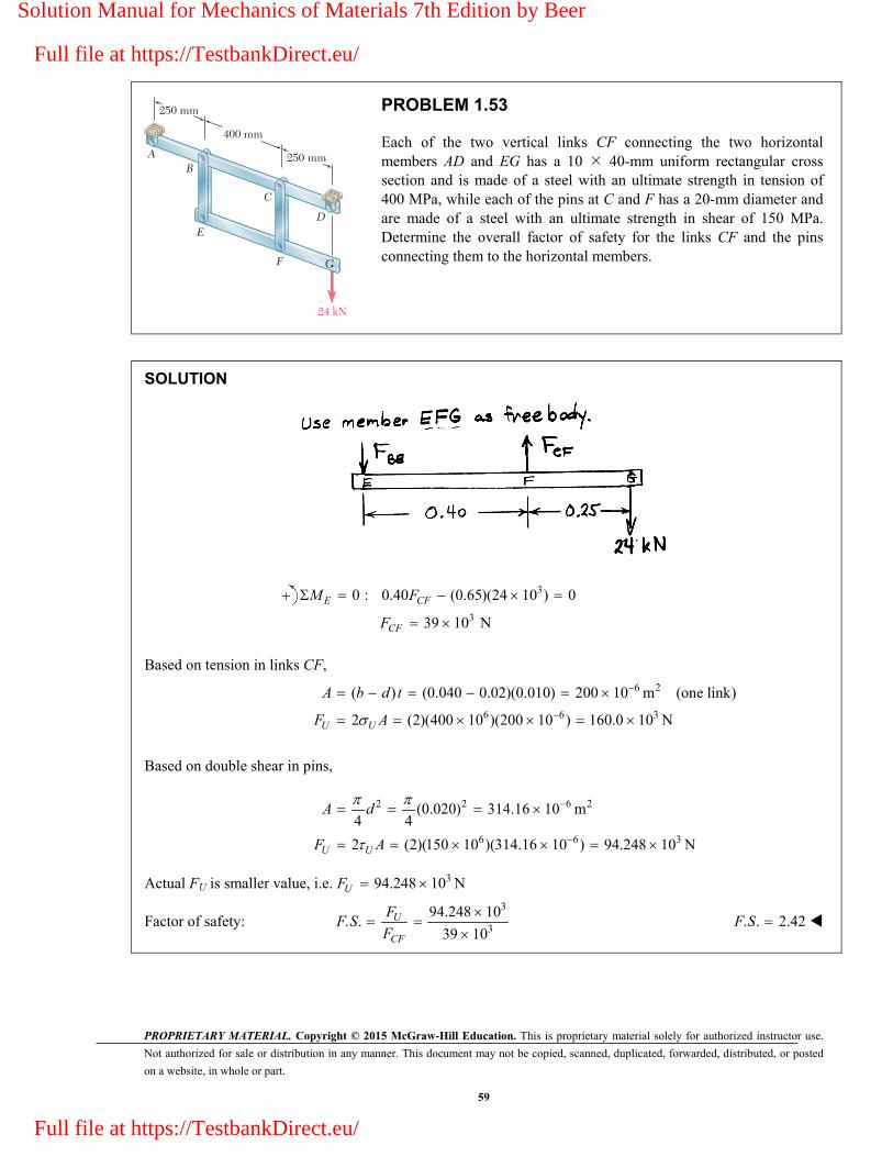
24 kN
C
AB
ED
F G
250 mm
400 mm
250 mm
PROBLEM 1.53
Each of the two vertical links CF connecting the two horizontal members AD and EG has a 10 40-mm uniform rectangular cross section and is made of a steel with an ultimate strength in tension of 400 MPa, while each of the pins at C and F has a 20-mm diameter and are made of a steel with an ultimate strength in shear of 150 MPa. Determine the overall factor of safety for the links CF and the pins connecting them to the horizontal members.
SOLUTION
3
3
0 : 0.40 (0.65)(24 10 ) 0
39 10 N
E CF
CF
M F
F
Based on tension in links CF,
6 2
6 6 3
( ) (0.040 0.02)(0.010) 200 10 m (one link)
2 (2)(400 10 )(200 10 ) 160.0 10 NU U
A b d t
F A
Based on double shear in pins,
2 2 6 2
6 6 3
(0.020) 314.16 10 m4 4
2 (2)(150 10 )(314.16 10 ) 94.248 10 NU U
A d
F A
Actual FU is smaller value, i.e. 394.248 10 NUF
Factor of safety: 3
3
94.248 10. .
39 10U
CF
FF S
F
. . 2.42F S
Solution Manual for Mechanics of Materials 7th Edition by Beer
Full file at https://TestbankDirect.eu/
Full file at https://TestbankDirect.eu/

PROPRIETARY MATERIAL. Copyright © 2015 McGraw-Hill Education. This is proprietary material solely for authorized instructor use.
Not authorized for sale or distribution in any manner. This document may not be copied, scanned, duplicated, forwarded, distributed, or posted
on a website, in whole or part.
60
24 kN
C
AB
ED
F G
250 mm
400 mm
250 mm
PROBLEM 1.54
Solve Prob. 1.53, assuming that the pins at C and F have been replaced by pins with a 30-mm diameter.
PROBLEM 1.53 Each of the two vertical links CF connecting the two horizontal members AD and EG has a 10 40-mm uniform rectangular cross section and is made of a steel with an ultimate strength in tension of 400 MPa, while each of the pins at C and F has a 20-mm diameter and are made of a steel with an ultimate strength in shear of 150 MPa. Determine the overall factor of safety for the links CF and the pins connecting them to the horizontal members.
SOLUTION
Use member EFG as free body.
3
3
0 : 0.40 (0.65)(24 10 ) 0
39 10 N
E CF
CF
M F
F
Based on tension in links CF,
6 2
6 6 3
( ) (0.040 0.030)(0.010) 100 10 m (one link)
2 (2)(400 10 )(100 10 ) 80.0 10 NU U
A b d t
F A
Based on double shear in pins,
2 2 6 2
6 6 3
(0.030) 706.86 10 m4 4
2 (2)(150 10 )(706.86 10 ) 212.06 10 NU U
A d
F A
Actual FU is smaller value, i.e. 380.0 10 NUF
Factor of safety: 3
3
80.0 10. .
39 10U
CF
FF S
F
. . 2.05F S
Solution Manual for Mechanics of Materials 7th Edition by Beer
Full file at https://TestbankDirect.eu/
Full file at https://TestbankDirect.eu/

PROPRIETARY MATERIAL. Copyright © 2015 McGraw-Hill Education. This is proprietary material solely for authorized instructor use.
Not authorized for sale or distribution in any manner. This document may not be copied, scanned, duplicated, forwarded, distributed, or posted
on a website, in whole or part.
61
180 mm200 mm
Top view
Side viewFront view
8 mm
20 mm8 mm
8 mm
12 mm
12 mm
B CB
D D
A
B CA
P
PROBLEM 1.55
In the structure shown, an 8-mm-diameter pin is used at A, and 12-mm-diameter pins are used at B and D. Knowing that the ultimate shearing stress is 100 MPa at all connections and that the ultimate normal stress is 250 MPa in each of the two links joining B and D, determine the allowable load P if an overall factor of safety of 3.0 is desired.
SOLUTION
Statics: Use ABC as free body.
10
0 : 0.20 0.18 09
B A AM F P P F
10
0 : 0.20 0.38 019
A BD BDM F P P F
Based on double shear in pin A, 2 2 6 2(0.008) 50.266 10 m4 4
A d
6 63
3
2 (2)(100 10 )(50.266 10 )3.351 10 N
. . 3.010
3.72 10 N9
UA
A
AF
F S
P F
Based on double shear in pins at B and D, 2 2 6 2(0.012) 113.10 10 m4 4
A d
6 63
3
2 (2)(100 10 )(113.10 10 )7.54 10 N
. . 3.010
3.97 10 N19
UBD
BD
AF
F S
P F
Based on compression in links BD, for one link, 6 2(0.020)(0.008) 160 10 m A
6 6
3
3
2 (2)(250 10 )(160 10 )26.7 10 N
. . 3.010
14.04 10 N19
UBD
BD
AF
F S
P F
Allowable value of P is smallest, 33.72 10 N P 3.72 kNP
Solution Manual for Mechanics of Materials 7th Edition by Beer
Full file at https://TestbankDirect.eu/
Full file at https://TestbankDirect.eu/

PROPRIETARY MATERIAL. Copyright © 2015 McGraw-Hill Education. This is proprietary material solely for authorized instructor use.
Not authorized for sale or distribution in any manner. This document may not be copied, scanned, duplicated, forwarded, distributed, or posted
on a website, in whole or part.
62
180 mm200 mm
Top view
Side viewFront view
8 mm
20 mm8 mm
8 mm
12 mm
12 mm
B CB
D D
A
B CA
P
PROBLEM 1.56
In an alternative design for the structure of Prob. 1.55, a pin of 10-mm-diameter is to be used at A. Assuming that all other specifications remain unchanged, determine the allowable load P if an overall factor of safety of 3.0 is desired.
PROBLEM 1.55 In the structure shown, an 8-mm-diameter pin is used at A, and 12-mm-diameter pins are used at B and D. Knowing that the ultimate shearing stress is 100 MPa at all connections and that the ultimate normal stress is 250 MPa in each of the two links joining B and D, determine the allowable load P if an overall factor of safety of 3.0 is desired.
SOLUTION
Statics: Use ABC as free body.
100: 0.20 0.18 0
9 B A AM F P P F
100: 0.20 0.38 0
19 A BD BDM F P P F
Based on double shear in pin A, 2 2 6 2(0.010) 78.54 10 m4 4
A d
6 63
3
2 (2)(100 10 )(78.54 10 )5.236 10 N
. . 3.010
5.82 10 N9
UA
A
AF
F S
P F
Based on double shear in pins at B and D, 2 2 6 2(0.012) 113.10 10 m4 4
A d
6 63
3
2 (2)(100 10 )(113.10 10 )7.54 10 N
. . 3.010
3.97 10 N19
UBD
BD
AF
F S
P F
Based on compression in links BD, for one link, 6 2(0.020)(0.008) 160 10 m A
6 6
3
3
2 (2)(250 10 )(160 10 )26.7 10 N
. . 3.010
14.04 10 N19
UBD
BD
AF
F S
P F
Allowable value of P is smallest, 33.97 10 N P 3.97 kNP
Solution Manual for Mechanics of Materials 7th Edition by Beer
Full file at https://TestbankDirect.eu/
Full file at https://TestbankDirect.eu/
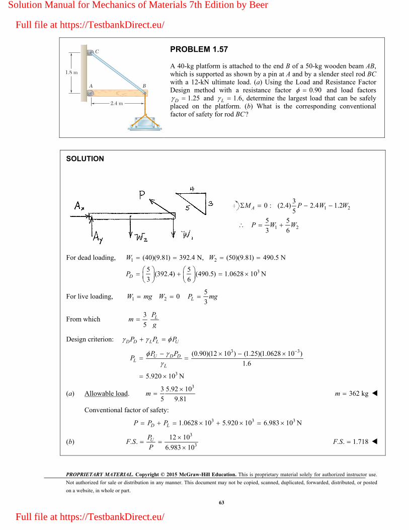
PROPRIETARY MATERIAL. Copyright © 2015 McGraw-Hill Education. This is proprietary material solely for authorized instructor use.
Not authorized for sale or distribution in any manner. This document may not be copied, scanned, duplicated, forwarded, distributed, or posted
on a website, in whole or part.
63
1.8 m
2.4 m
A B
C
PROBLEM 1.57
A 40-kg platform is attached to the end B of a 50-kg wooden beam AB, which is supported as shown by a pin at A and by a slender steel rod BC with a 12-kN ultimate load. (a) Using the Load and Resistance Factor Design method with a resistance factor 0.90 and load factors
1.25 D and L 1.6, determine the largest load that can be safely placed on the platform. (b) What is the corresponding conventional factor of safety for rod BC?
SOLUTION
1 2
1 2
30 : (2.4) 2.4 1.2
55 5
3 6
AM P W W
P W W
For dead loading, 1 2
3
(40)(9.81) 392.4 N, (50)(9.81) 490.5 N
5 5(392.4) (490.5) 1.0628 10 N
3 6
D
W W
P
For live loading, 1 2 0W mg W 5
3LP mg
From which 3
5 LP
mg
Design criterion: D D L L UP P P
3 3
3
(0.90)(12 10 ) (1.25)(1.0628 10 )
1.6
5.920 10 N
U D DL
L
P PP
(a) Allowable load. 33 5.92 10
5 9.81
m 362 kgm
Conventional factor of safety:
3 3 31.0628 10 5.920 10 6.983 10 N D LP P P
(b) 3
3
12 10. .
6.983 10
UP
F SP
. . 1.718F S
Solution Manual for Mechanics of Materials 7th Edition by Beer
Full file at https://TestbankDirect.eu/
Full file at https://TestbankDirect.eu/
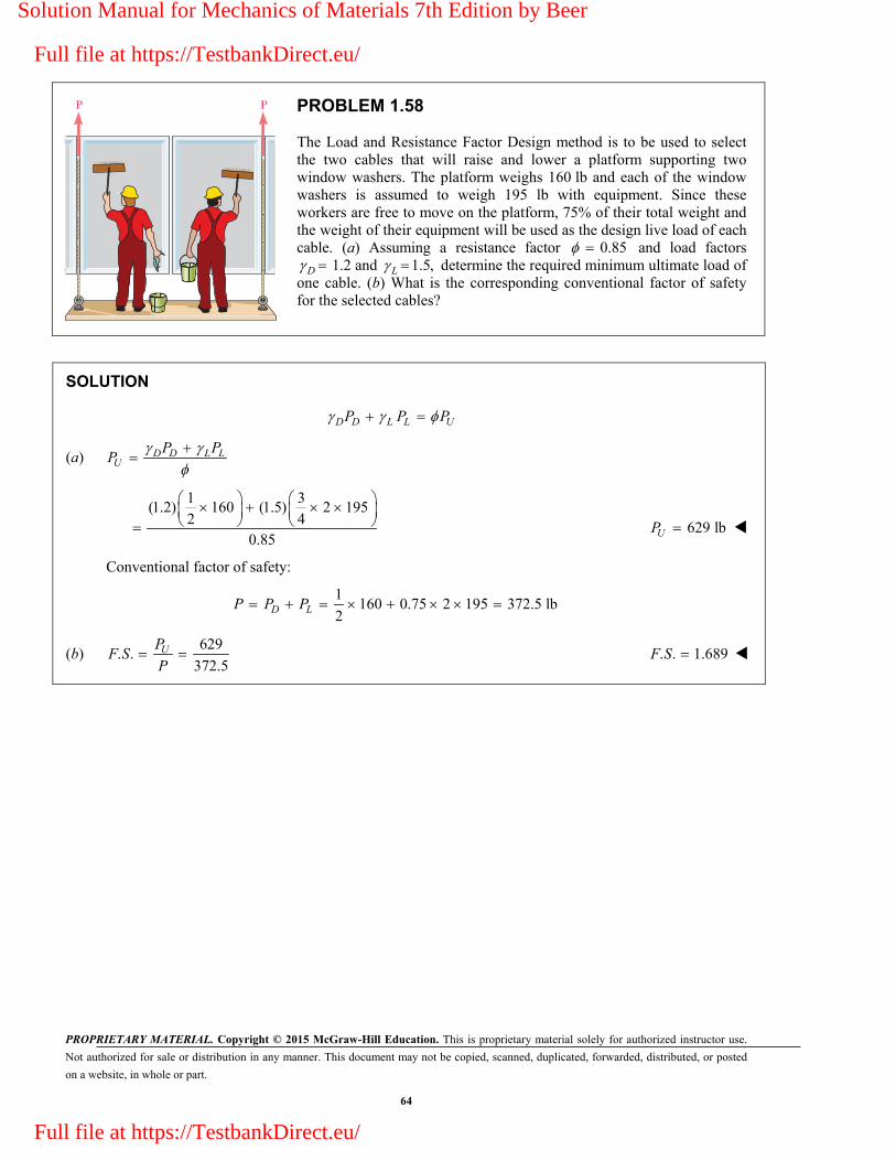
PROPRIETARY MATERIAL. Copyright © 2015 McGraw-Hill Education. This is proprietary material solely for authorized instructor use.
Not authorized for sale or distribution in any manner. This document may not be copied, scanned, duplicated, forwarded, distributed, or posted
on a website, in whole or part.
64
P P
PROBLEM 1.58
The Load and Resistance Factor Design method is to be used to select the two cables that will raise and lower a platform supporting two window washers. The platform weighs 160 lb and each of the window washers is assumed to weigh 195 lb with equipment. Since these workers are free to move on the platform, 75% of their total weight and the weight of their equipment will be used as the design live load of each cable. (a) Assuming a resistance factor 0.85 and load factors
D 1.2 and 1.5,L determine the required minimum ultimate load of one cable. (b) What is the corresponding conventional factor of safety for the selected cables?
SOLUTION
D D L L UP P P
(a)
D D L LU
P PP
1 3(1.2) 160 (1.5) 2 195
2 40.85
629 lbUP
Conventional factor of safety:
1
160 0.75 2 195 372.5 lb2
D LP P P
(b) 629
. .372.5
UPF S
P . . 1.689F S
Solution Manual for Mechanics of Materials 7th Edition by Beer
Full file at https://TestbankDirect.eu/
Full file at https://TestbankDirect.eu/

PROPRIETARY MATERIAL. Copyright © 2015 McGraw-Hill Education. This is proprietary material solely for authorized instructor use.
Not authorized for sale or distribution in any manner. This document may not be copied, scanned, duplicated, forwarded, distributed, or posted
on a website, in whole or part.
65
AD
C
B
3 m25 m15 m
35 m
80 Mg
15 m
PROBLEM 1.59
In the marine crane shown, link CD is known to have a uniform cross section of 50 150 mm. For the loading shown, determine`` the normal stress in the central portion of that link.
SOLUTION
Weight of loading: 2(80 Mg)(9.81 m/s ) 784.8 kN W
Free Body: Portion ABC.
0: (15 m) (28 m) 0
28 28(784.8 kN)
15 151465 kN
A CD
CD
CD
M F W
F W
F
3
61465 10 N195.3 10 Pa
(0.050 m)(0.150 m)
CDCD
F
A 195.3 MPaCD
Solution Manual for Mechanics of Materials 7th Edition by Beer
Full file at https://TestbankDirect.eu/
Full file at https://TestbankDirect.eu/

PROPRIETARY MATERIAL. Copyright © 2015 McGraw-Hill Education. This is proprietary material solely for authorized instructor use.
Not authorized for sale or distribution in any manner. This document may not be copied, scanned, duplicated, forwarded, distributed, or posted
on a website, in whole or part.
66
B
A
C
0.5 in.
0.5 in.
1.8 in.
1.8 in.
45�
60�
5 kips5 kips
PROBLEM 1.60
Two horizontal 5-kip forces are applied to pin B of the assembly shown. Knowing that a pin of 0.8-in. diameter is used at each connection, determine the maximum value of the average normal stress (a) in link AB, (b) in link BC.
SOLUTION
Use joint B as free body.
Law of Sines:
10
sin 45 sin 60 sin 95
AB BCF F
7.3205 kipsABF
8.9658 kipsBCF
Link AB is a tension member.
Minimum section at pin: 2net (1.8 0.8)(0.5) 0.5 inA
(a) Stress in net
7.3205:
0.5AB
ABF
ABA
14.64 ksi AB
Link BC is a compression member.
Cross sectional area is 2(1.8)(0.5) 0.9 inA
(b) Stress in BC: 8.9658
0.9
BCBC
F
A 9.96 ksi BC
Solution Manual for Mechanics of Materials 7th Edition by Beer
Full file at https://TestbankDirect.eu/
Full file at https://TestbankDirect.eu/

PROPRIETARY MATERIAL. Copyright © 2015 McGraw-Hill Education. This is proprietary material solely for authorized instructor use.
Not authorized for sale or distribution in any manner. This document may not be copied, scanned, duplicated, forwarded, distributed, or posted
on a website, in whole or part.
67
B
A
C
0.5 in.
0.5 in.
1.8 in.
1.8 in.
45�
60�
5 kips5 kips
PROBLEM 1.61
For the assembly and loading of Prob. 1.60, determine (a) the average shearing stress in the pin at C, (b) the average bearing stress at C in member BC, (c) the average bearing stress at B in member BC.
PROBLEM 1.60 Two horizontal 5-kip forces are applied to pin B of the assembly shown. Knowing that a pin of 0.8-in. diameter is used at each connection, determine the maximum value of the average normal stress (a) in link AB, (b) in link BC.
SOLUTION
Use joint B as free body.
Law of Sines:
10
8.9658 kipssin 45 sin 60 sin 95
AB BCBC
F FF
(a) Shearing stress in pin at C. 2
BC
P
F
A
2 2 2(0.8) 0.5026 in4 4
8.96588.92
(2)(0.5026)
PA d
8.92 ksi
Solution Manual for Mechanics of Materials 7th Edition by Beer
Full file at https://TestbankDirect.eu/
Full file at https://TestbankDirect.eu/
PROPRIETARY MATERIAL. Copyright © 2015 McGraw-Hill Education. This is proprietary material solely for authorized instructor use.
Not authorized for sale or distribution in any manner. This document may not be copied, scanned, duplicated, forwarded, distributed, or posted
on a website, in whole or part.
68
PROBLEM 1.61 (Continued)
(b) Bearing stress at C in member BC. BCb
F
A
2(0.5)(0.8) 0.4 in
8.965822.4
0.4
b
A td
22.4 ksi b
(c) Bearing stress at B in member BC. BCb
F
A
22 2(0.5)(0.8) 0.8 in
8.965811.21
0.8
b
A td
11.21 ksi b
Solution Manual for Mechanics of Materials 7th Edition by Beer
Full file at https://TestbankDirect.eu/
Full file at https://TestbankDirect.eu/
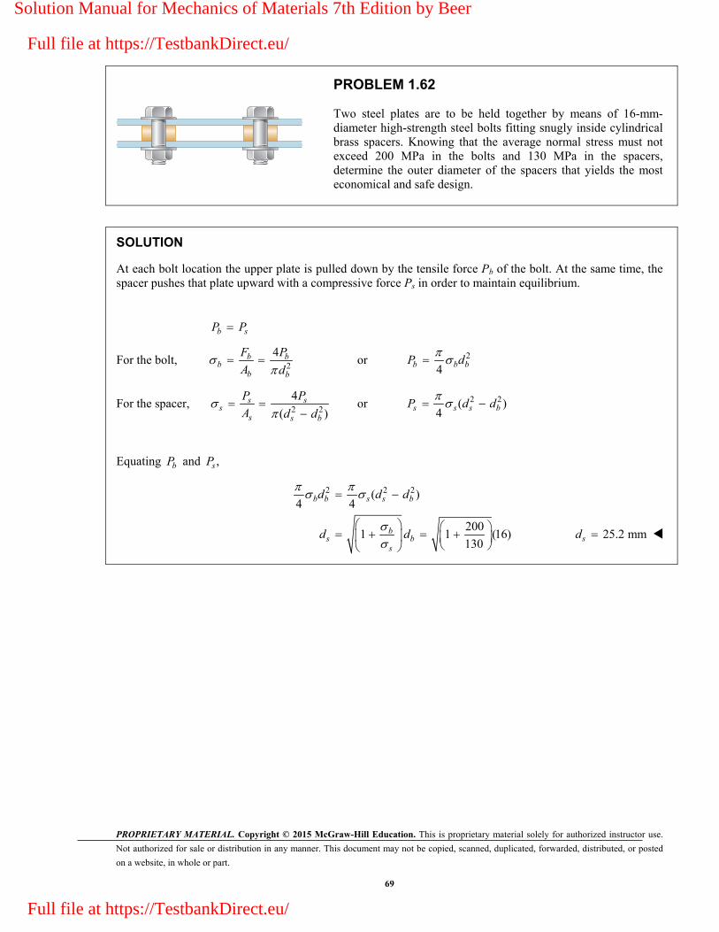
PROPRIETARY MATERIAL. Copyright © 2015 McGraw-Hill Education. This is proprietary material solely for authorized instructor use.
Not authorized for sale or distribution in any manner. This document may not be copied, scanned, duplicated, forwarded, distributed, or posted
on a website, in whole or part.
69
PROBLEM 1.62
Two steel plates are to be held together by means of 16-mm-diameter high-strength steel bolts fitting snugly inside cylindrical brass spacers. Knowing that the average normal stress must not exceed 200 MPa in the bolts and 130 MPa in the spacers, determine the outer diameter of the spacers that yields the most economical and safe design.
SOLUTION
At each bolt location the upper plate is pulled down by the tensile force Pb of the bolt. At the same time, the spacer pushes that plate upward with a compressive force Ps in order to maintain equilibrium.
b sP P
For the bolt, 2
4
b bb
b b
F P
A d or 2
4
b b bP d
For the spacer, 2 2
4
( )
s s
ss s b
P P
A d d or 2 2( )
4
s s s bP d d
Equating bP and ,sP
2 2 2( )4 4
2001 1 (16)
130
b b s s b
bs b
s
d d d
d d
25.2 mmsd
Solution Manual for Mechanics of Materials 7th Edition by Beer
Full file at https://TestbankDirect.eu/
Full file at https://TestbankDirect.eu/

PROPRIETARY MATERIAL. Copyright © 2015 McGraw-Hill Education. This is proprietary material solely for authorized instructor use.
Not authorized for sale or distribution in any manner. This document may not be copied, scanned, duplicated, forwarded, distributed, or posted
on a website, in whole or part.
70
200 mm
80 mmM
60 mm
B
A
C
P
PROBLEM 1.63
A couple M of magnitude 1500 N m is applied to the crank of an engine. For the position shown, determine (a) the force P required to hold the engine system in equilibrium, (b) the average normal stress in the connecting rod BC, which has a 450-mm2 uniform cross section.
SOLUTION
Use piston, rod, and crank together as free body. Add wall reaction H and bearing reactions Ax and Ay.
3
0 : (0.280 m) 1500 N m 0
5.3571 10 N
AM H
H
Use piston alone as free body. Note that rod is a two-force member; hence the direction of force FBC is known. Draw the force triangle and solve for P and FBE by proportions.
2 2
3
200 60 208.81 mm
20017.86 10 N
60
l
PP
H
(a) 17.86 kNP
3208.8118.6436 10 N
60BC
BCF
FH
Rod BC is a compression member. Its area is
2 6 2450 mm 450 10 m
Stress:
3
66
18.6436 1041.430 10 Pa
450 10
BC
BCF
A
(b) 41.4 MPa BC
Solution Manual for Mechanics of Materials 7th Edition by Beer
Full file at https://TestbankDirect.eu/
Full file at https://TestbankDirect.eu/

PROPRIETARY MATERIAL. Copyright © 2015 McGraw-Hill Education. This is proprietary material solely for authorized instructor use.
Not authorized for sale or distribution in any manner. This document may not be copied, scanned, duplicated, forwarded, distributed, or posted
on a website, in whole or part.
71
60 lb
F
D
E
JC D
B
A
8 in.
2 in.
4 in. 12 in. 4 in.
6 in.
�
PROBLEM 1.64
Knowing that the link DE is 18
in. thick and 1 in. wide, determine the normal stress in the central portion of that link when (a) 0 , (b) 90 .
SOLUTION
Use member CEF as a free body.
0 : 12 (8)(60 sin ) (16)(60 cos ) 0
40 sin 80 cos lb
C DE
DE
M F
F
21(1) 0.125 in
8
DE
DEDE
DE
A
F
A
(a) 0: 80 lb DEF
80
0.125
DE 640 psi DE
(b) 90 : 40 lb DEF
40
0.125
DE 320 psi DE
Solution Manual for Mechanics of Materials 7th Edition by Beer
Full file at https://TestbankDirect.eu/
Full file at https://TestbankDirect.eu/

PROPRIETARY MATERIAL. Copyright © 2015 McGraw-Hill Education. This is proprietary material solely for authorized instructor use.
Not authorized for sale or distribution in any manner. This document may not be copied, scanned, duplicated, forwarded, distributed, or posted
on a website, in whole or part.
72
DA
CB
b
1500 lb
750 lb
750 lb
4 in.
1 in.
PROBLEM 1.65
A 58
-in.-diameter steel rod AB is fitted to a round hole near end C of the wooden member CD. For the loading shown, determine (a) the maximum average normal stress in the wood, (b) the distance b for which the average shearing stress is 100 psi on the surfaces indicated by the dashed lines, (c) the average bearing stress on the wood.
SOLUTION
(a) Maximum normal stress in the wood.
2net
net
5(1) 4 3.375 in
8
1500444 psi
3.375
A
P
A 444 psi
(b) Distance b for = 100 psi.
For sheared area see dotted lines.
21500
7.50 in.2 (2)(1)(100)
P P
A btP
bt
7.50 in.b
(c) Average bearing stress on the wood.
1500
2400 psi5
(1)8
bb
P P
A dt 2400 psi b
Solution Manual for Mechanics of Materials 7th Edition by Beer
Full file at https://TestbankDirect.eu/
Full file at https://TestbankDirect.eu/

PROPRIETARY MATERIAL. Copyright © 2015 McGraw-Hill Education. This is proprietary material solely for authorized instructor use.
Not authorized for sale or distribution in any manner. This document may not be copied, scanned, duplicated, forwarded, distributed, or posted
on a website, in whole or part.
73
18 mm
Top view
Side view
Front view
160 mm 120 mm
6 mm
A
A
BC
B
D
C
B
D
P
PROBLEM 1.66
In the steel structure shown, a 6-mm-diameter pin is used at C and 10-mm-diameter pins are used at B and D. The ultimate shearing stress is 150 MPa at all connections, and the ultimate normal stress is 400 MPa in link BD. Knowing that a factor of safety of 3.0 is desired, determine the largest load P that can be applied at A. Note that link BD is not reinforced around the pin holes.
SOLUTION
Use free body ABC.
0 : 0.280 0.120 0 C BDM P F
3
7 BDP F (1)
0 : 0.160 0.120 0BM P C
3
4P C (2)
Tension on net section of link BD:
6
3 3 3net net
400 10(6 10 )(18 10)(10 ) 6.40 10 N
. . 3
U
BDF A AF S
Shear in pins at B and D:
6
2 3 2 3pin
150 10(10 10 ) 3.9270 10 N
. . 4 3 4
U
BDF A dF S
Smaller value of FBD is 33.9270 10 N.
From (1), 3 33(3.9270 10 ) 1.683 10 N
7
P
Shear in pin at C: 6
2 3 2 3pin
150 102 2 (2) (6 10 ) 2.8274 10 N
. . 4 3 4
UC A d
F S
From (2), 3 33(2.8274 10 ) 2.12 10 N
4
P
Smaller value of P is allowable value. 31.683 10 N P 1.683 kNP
Solution Manual for Mechanics of Materials 7th Edition by Beer
Full file at https://TestbankDirect.eu/
Full file at https://TestbankDirect.eu/

PROPRIETARY MATERIAL. Copyright © 2015 McGraw-Hill Education. This is proprietary material solely for authorized instructor use.
Not authorized for sale or distribution in any manner. This document may not be copied, scanned, duplicated, forwarded, distributed, or posted
on a website, in whole or part.
74
A
D
B
C
0.4 m
30�
40�
0.8 m
0.6 m
P
PROBLEM 1.67
Member ABC, which is supported by a pin and bracket at C and a cable BD, was designed to support the 16-kN load P as shown. Knowing that the ultimate load for cable BD is 100 kN, determine the factor of safety with respect to cable failure.
SOLUTION
Use member ABC as a free body, and note that member BD is a two-force member.
0 : ( cos 40 )(1.2) ( sin 40 )(0.6)
( cos30 )(0.6)
( sin 30 )(0.4) 0
1.30493 0.71962 0
c
BD
BD
BD
M P P
F
F
P F
3 3
3
3
3
1.81335 (1.81335)(16 10 ) 29.014 10 N
100 10 N
100 10. .
29.014 10
BD
U
U
BD
F P
F
FF S
F . . 3.45F S
Solution Manual for Mechanics of Materials 7th Edition by Beer
Full file at https://TestbankDirect.eu/
Full file at https://TestbankDirect.eu/

PROPRIETARY MATERIAL. Copyright © 2015 McGraw-Hill Education. This is proprietary material solely for authorized instructor use.
Not authorized for sale or distribution in any manner. This document may not be copied, scanned, duplicated, forwarded, distributed, or posted
on a website, in whole or part.
75
PL d
PROBLEM 1.68
A force P is applied as shown to a steel reinforcing bar that has been embedded in a block of concrete. Determine the smallest length L for which the full allowable normal stress in the bar can be developed. Express the result in terms of the diameter d of the bar, the allowable normal stress all in the steel, and the average allowable bond stress all between the concrete and the cylindrical surface of the bar. (Neglect the normal stresses between the concrete and the end of the bar.)
SOLUTION
For shear,
all all
A dL
P A dL
For tension, 2
2all all
4
4
A d
P A d
Equating, 2all all 4
dL d
Solving for L, min all all/4 L d
Solution Manual for Mechanics of Materials 7th Edition by Beer
Full file at https://TestbankDirect.eu/
Full file at https://TestbankDirect.eu/

PROPRIETARY MATERIAL. Copyright © 2015 McGraw-Hill Education. This is proprietary material solely for authorized instructor use.
Not authorized for sale or distribution in any manner. This document may not be copied, scanned, duplicated, forwarded, distributed, or posted
on a website, in whole or part.
76
A
1.25 in.
2.4 kips
2.0 in.
B
�
PROBLEM 1.69
The two portions of member AB are glued together along a plane forming an angle with the horizontal. Knowing that the ultimate stress for the glued joint is 2.5 ksi in tension and 1.3 ksi in shear, determine (a) the value of for which the factor of safety of the member is maximum, (b) the corresponding value of the factor of safety. (Hint: Equate the expressions obtained for the factors of safety with respect to the normal and shearing stresses.)
SOLUTION
20 (2.0)(1.25) 2.50 inA
At the optimum angle, ( . .) ( . .) F S F S
Normal stress: 02, 2
0
coscos
UU
APP
A
0,2
( . .)cos
UU APF S
P P
Shearing stress: 0,
0
0,
sin cossin cos
( . .)sin cos
UU
UU
APP
A
APF S
P P
Equating, 0 02 sin coscos
U UA A
PP
Solving, sin 1.3
tan 0.520cos 2.5
U
U
(a) opt 27.5
(b) 02 2
(12.5)(2.50)7.94 kips
cos cos 27.5U
UA
P
7.94
. .2.4
UPF S
P . . 3.31F S
Solution Manual for Mechanics of Materials 7th Edition by Beer
Full file at https://TestbankDirect.eu/
Full file at https://TestbankDirect.eu/

PROPRIETARY MATERIAL. Copyright © 2015 McGraw-Hill Education. This is proprietary material solely for authorized instructor use.
Not authorized for sale or distribution in any manner. This document may not be copied, scanned, duplicated, forwarded, distributed, or posted
on a website, in whole or part.
77
A
1.25 in.
2.4 kips
2.0 in.
B
�
PROBLEM 1.70
The two portions of member AB are glued together along a plane forming an angle with the horizontal. Knowing that the ultimate stress for the glued joint is 2.5 ksi in tension and 1.3 ksi in shear, determine the range of values of for which the factor of safety of the members is at least 3.0.
SOLUTION
20 (2.0)(1.25) 2.50 in.
2.4 kips
( . .) 7.2 kipsU
A
P
P F S P
Based on tensile stress,
2
0
02
cos
(2.5)(2.50)cos 0.86806
7.2
UU
U
U
P
A
A
P
cos 0.93169 21.3 21.3
Based on shearing stress, 0 0
sin cos sin 22
U UU
P P
A A
02 (2)(2.50)(1.3)sin 2 0.90278
7.2
U
U
A
P
2 64.52 32.3 32.3
Hence, 21.3 32.3
Solution Manual for Mechanics of Materials 7th Edition by Beer
Full file at https://TestbankDirect.eu/
Full file at https://TestbankDirect.eu/
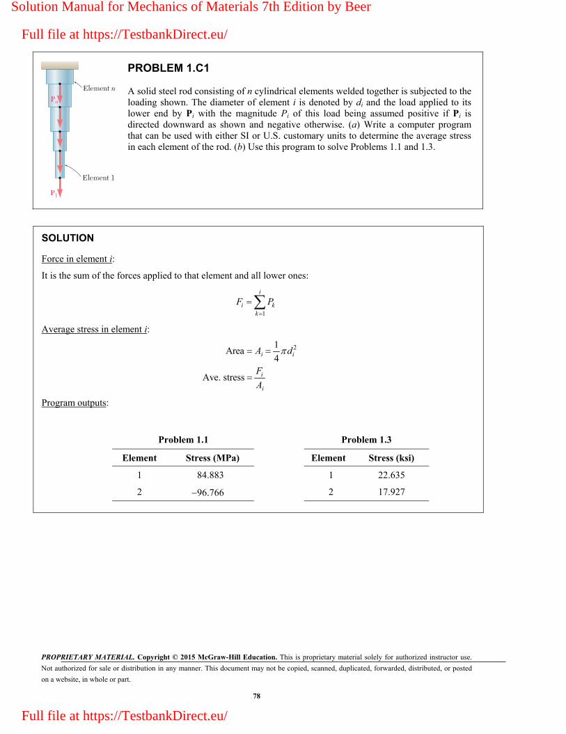
PROPRIETARY MATERIAL. Copyright © 2015 McGraw-Hill Education. This is proprietary material solely for authorized instructor use.
Not authorized for sale or distribution in any manner. This document may not be copied, scanned, duplicated, forwarded, distributed, or posted
on a website, in whole or part.
78
Element n
Element 1
Pn
P1
PROBLEM 1.C1
A solid steel rod consisting of n cylindrical elements welded together is subjected to the loading shown. The diameter of element i is denoted by di and the load applied to its lower end by Pi with the magnitude Pi of this load being assumed positive if Pi is directed downward as shown and negative otherwise. (a) Write a computer program that can be used with either SI or U.S. customary units to determine the average stress in each element of the rod. (b) Use this program to solve Problems 1.1 and 1.3.
SOLUTION
Force in element i:
It is the sum of the forces applied to that element and all lower ones:
1
i
i kk
F P
Average stress in element i:
21Area
4
Ave. stress
i i
i
i
A d
F
A
Program outputs:
Problem 1.1 Problem 1.3
Element Stress (MPa) Element Stress (ksi)
1 84.883 1 22.635
2 96.766 2 17.927
Solution Manual for Mechanics of Materials 7th Edition by Beer
Full file at https://TestbankDirect.eu/
Full file at https://TestbankDirect.eu/

PROPRIETARY MATERIAL. Copyright © 2015 McGraw-Hill Education. This is proprietary material solely for authorized instructor use.
Not authorized for sale or distribution in any manner. This document may not be copied, scanned, duplicated, forwarded, distributed, or posted
on a website, in whole or part.
79
0.2 m0.25 m
0.4 m
20 kN
C
B
AD
E
PROBLEM 1.C2
A 20-kN load is applied as shown to the horizontal member ABC. Member ABC has a 10 50-mm uniform rectangular cross section and is supported by four vertical links, each of 8 36-mm uniform rectangular cross section. Each of the four pins at A, B, C, and D has the same diameter d and is in double shear. (a) Write a computer program to calculate for values of d from 10 to 30 mm, using 1-mm increments, (i) the maximum value of the average normal stress in the links connecting pins B and D, (ii) the average normal stress in the links connecting pins C and E, (iii) the average shearing stress in pin B, (iv) the average shearing stress in pin C, (v) the average bearing stress at B in member ABC, and (vi) the average bearing stress at C in member ABC. (b) Check your program by comparing the values obtained for d 16 mm with the answers given for Probs. 1.7 and 1.27. (c) Use this program to find the permissible values of the diameter d of the pins, knowing that the allowable values of the normal, shearing, and bearing stresses for the steel used are, respectively, 150 MPa, 90 MPa, and 230 MPa. (d) Solve Part c, assuming that the thickness of member ABC has been reduced from 10 to 8 mm.
SOLUTION
Forces in links.
F.B. diagram of ABC: 0: 2 ( ) ( ) 0
( )/2( ) (tension)C BD
BD
M F BC P AC
F P AC BC
0: 2 ( ) ( ) 0
( )/2( ) (comp.)B CE
CE
M F BC P AB
F P AB BC
(i) Link BD.
Thickness Lt
( )
/BD L L
BD BD BD
A t w d
F A
(iii) Pin B.
2/( /4)B BDF d
(v) Bearing stress at B.
Thickness of member ACAC t
Sig Bear /( )BD ACB F dt
(vi) Bearing stress at C.
Sig Bear /( )CE ACC F dt
(ii) Link CE. Thickness Lt
/
CE L L
CE CE CE
A t w
F A
(iv) Pin C.
2/( /4)C CEF d
Shearing stress in ABC under Pin B.
( /2)
0: 2 2
2
B AC AC AC
y B BD
BDAC
AC AC
F t w
F F F
F
w
P = 20 kN
Solution Manual for Mechanics of Materials 7th Edition by Beer
Full file at https://TestbankDirect.eu/
Full file at https://TestbankDirect.eu/

PROPRIETARY MATERIAL. Copyright © 2015 McGraw-Hill Education. This is proprietary material solely for authorized instructor use.
Not authorized for sale or distribution in any manner. This document may not be copied, scanned, duplicated, forwarded, distributed, or posted
on a website, in whole or part.
80
PROBLEM 1.C2 (Continued)
Program Outputs
Input data for Parts (a), (b), (c):
P 20 kN, AB 0.25 m, BC 0.40 m, AC 0.65 m,
TL 8 mm, WL 36 mm, TAC 10 mm, WAC 50 mm
(c) Answer: 16 mm 22 mmd (c)
Check: For d 22 mm, Tau AC = 65 MPa < 90 MPa O.K.
Solution Manual for Mechanics of Materials 7th Edition by Beer
Full file at https://TestbankDirect.eu/
Full file at https://TestbankDirect.eu/

PROPRIETARY MATERIAL. Copyright © 2015 McGraw-Hill Education. This is proprietary material solely for authorized instructor use.
Not authorized for sale or distribution in any manner. This document may not be copied, scanned, duplicated, forwarded, distributed, or posted
on a website, in whole or part.
81
PROBLEM 1.C2 (Continued)
Input data for Part (d): P 20 kN,
AB = 0.25 m, BC = 0.40 m,
AC = 0.65 m, TL = 8 mm, WL = 36 mm,
TAC 8 mm, WAC 50 mm
(d) Answer: 18 mm 22 mmd (d) Check: For d = 22 mm, Tau AC = 81.25 MPa < 90 MPa O.K.
Solution Manual for Mechanics of Materials 7th Edition by Beer
Full file at https://TestbankDirect.eu/
Full file at https://TestbankDirect.eu/
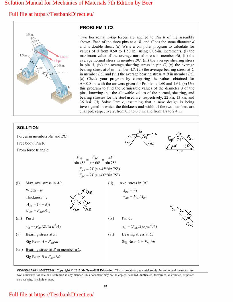
PROPRIETARY MATERIAL. Copyright © 2015 McGraw-Hill Education. This is proprietary material solely for authorized instructor use.
Not authorized for sale or distribution in any manner. This document may not be copied, scanned, duplicated, forwarded, distributed, or posted
on a website, in whole or part.
82
B
A
C
0.5 in.
0.5 in.
1.8 in.
1.8 in.
45�
60�
5 kips5 kips
PROBLEM 1.C3
Two horizontal 5-kip forces are applied to Pin B of the assembly shown. Each of the three pins at A, B, and C has the same diameter d and is double shear. (a) Write a computer program to calculate for values of d from 0.50 to 1.50 in., using 0.05-in. increments, (i) the maximum value of the average normal stress in member AB, (ii) the average normal stress in member BC, (iii) the average shearing stress in pin A, (iv) the average shearing stress in pin C, (v) the average bearing stress at A in member AB, (vi) the average bearing stress at C in member BC, and (vii) the average bearing stress at B in member BC. (b) Check your program by comparing the values obtained for d 0.8 in. with the answers given for Problems 1.60 and 1.61. (c) Use this program to find the permissible values of the diameter d of the pins, knowing that the allowable values of the normal, shearing, and bearing stresses for the steel used are, respectively, 22 ksi, 13 ksi, and 36 ksi. (d) Solve Part c, assuming that a new design is being investigated in which the thickness and width of the two members are changed, respectively, from 0.5 to 0.3 in. and from 1.8 to 2.4 in.
SOLUTION
Forces in members AB and BC.
Free body: Pin B.
From force triangle:
2
sin 45 sin 60 sin 75
2 (sin 45 /sin 75 )
2 (sin 60 /sin 75 )
BCAB
AB
BC
FF P
F P
F P
(i) Max. ave. stress in AB.
Width w
Thickness t
( )
/AB
AB AB AB
A w d t
F A
(iii) Pin A.
2( /2)/( /4)A ABF d
(v) Bearing stress at A.
Sig Bear /ABA F dt
(vii) Bearing stress at B in member BC.
Sig Bear /2BCB F dt
(ii) Ave. stress in BC.
/
BC
BC BC BC
A wt
F A
(iv) Pin C.
2( /2) /( /4)C BCF d
(vi) Bearing stress at C.
Sig Bear /BCC F dt
Solution Manual for Mechanics of Materials 7th Edition by Beer
Full file at https://TestbankDirect.eu/
Full file at https://TestbankDirect.eu/

PROPRIETARY MATERIAL. Copyright © 2015 McGraw-Hill Education. This is proprietary material solely for authorized instructor use.
Not authorized for sale or distribution in any manner. This document may not be copied, scanned, duplicated, forwarded, distributed, or posted
on a website, in whole or part.
83
PROBLEM 1.C3 (Continued)
Program Outputs
Input data for Parts (a), (b), (c):
P = 5 kips, w = 1.8 in., t = 0.5 in.
(c) Answer: 0.70 in. 1.10 in.d (c)
Solution Manual for Mechanics of Materials 7th Edition by Beer
Full file at https://TestbankDirect.eu/
Full file at https://TestbankDirect.eu/

PROPRIETARY MATERIAL. Copyright © 2015 McGraw-Hill Education. This is proprietary material solely for authorized instructor use.
Not authorized for sale or distribution in any manner. This document may not be copied, scanned, duplicated, forwarded, distributed, or posted
on a website, in whole or part.
84
PROBLEM 1.C3 (Continued)
Input data for Part (d),
P = 5 kips, w 2.4 in., t 0.3 in.
(d) Answer: 0.85 in. 1.25 in.d (d)
Solution Manual for Mechanics of Materials 7th Edition by Beer
Full file at https://TestbankDirect.eu/
Full file at https://TestbankDirect.eu/

PROPRIETARY MATERIAL. Copyright © 2015 McGraw-Hill Education. This is proprietary material solely for authorized instructor use.
Not authorized for sale or distribution in any manner. This document may not be copied, scanned, duplicated, forwarded, distributed, or posted
on a website, in whole or part.
85
a
bA
D
B
C
12 in.18 in.
15 in.
P
PROBLEM 1.C4
A 4-kip force P forming an angle with the vertical is applied as shown to member ABC, which is supported by a pin and bracket at C and by a cable BD forming an angle with the horizontal. (a) Knowing that the ultimate load of the cable is 25 kips, write a computer program to construct a table of the values of the factor of safety of the cable for values of and from 0 to 45, using increments in and corresponding to 0.1 increments in tan and tan . (b) Check that for any given value of , the maximum value of the factor of safety is obtained for 38.66 and explain why. (c) Determine the smallest possible value of the factor of safety for 38.66 , as well as the corresponding value of , and explain the result obtained.
SOLUTION
(a) Draw F.B. diagram of ABC:
ult
0 : ( sin )(1.5 in.) ( cos )(30 in.)
( cos )(15 in.) ( sin )(12 in.) 0
15 sin 30 cos
15 cos 12 sin
. . /
CM P P
F F
F P
F S F F
ultOutput for 4 kips and 20 kips: P F
(b) When 38.66°, tan 0.8 and cable BD is perpendicular to the lever arm BC.
(c) . . 3.579F S for 26.6 ; P is perpendicular to the lever arm AC.
Note: The value . . 3.579F S is the smallest of the values of F.S. corresponding to 38.66 and the largest of those corresponding to 26.6 . The point 26.6 , 38.66 is a “saddle point,” or “minimax” of the function . . ( , ).F S
Solution Manual for Mechanics of Materials 7th Edition by Beer
Full file at https://TestbankDirect.eu/
Full file at https://TestbankDirect.eu/

PROPRIETARY MATERIAL. Copyright © 2015 McGraw-Hill Education. This is proprietary material solely for authorized instructor use.
Not authorized for sale or distribution in any manner. This document may not be copied, scanned, duplicated, forwarded, distributed, or posted
on a website, in whole or part.
86
Pa
b
P'
a
PROBLEM 1.C5
A load P is supported as shown by two wooden members of uniform rectangular cross section that are joined by a simple glued scarf splice. (a) Denoting by U and ,U respectively, the ultimate strength of the joint in tension and in shear, write a computer program which, for given values of a, b, P, U and ,U expressed in either SI or U.S. customary units, and for values of from 5 to 85 at 5 intervals, can be used to calculate (i) the normal stress in the joint, (ii) the shearing stress in the joint, (iii) the factor of safety relative to failure in tension, (iv) the factor of safety relative to failure in shear, and (v) the overall factor of safety for the glued joint. (b) Apply this program, using the dimensions and loading of the members of Probs. 1.29 and 1.31, knowing that 150 psi U and 214 psi U for the glue used in Prob. 1.29, and that 1.26 MPa U and 1.50 MPa U for the glue used in Prob. 1.31. (c) Verify in each of these two cases that the shearing stress is maximum for 45 .a
SOLUTION
(i) and (ii) Draw the F.B. diagram of lower member:
0: cos 0 cos xF V P V P
0: sin 0 yF F P sinF P
Area /sinab
Normal stress: 2( / ) sinArea
FP ab
Shearing stress: ( / ) sin cosArea
VP ab
(iii) F.S. for tension (normal stresses):
/UFSN
(iv) F.S. for shear:
/UFSS
(v) Overall F.S.:
F.S. The smaller of FSN and FSS.
Solution Manual for Mechanics of Materials 7th Edition by Beer
Full file at https://TestbankDirect.eu/
Full file at https://TestbankDirect.eu/
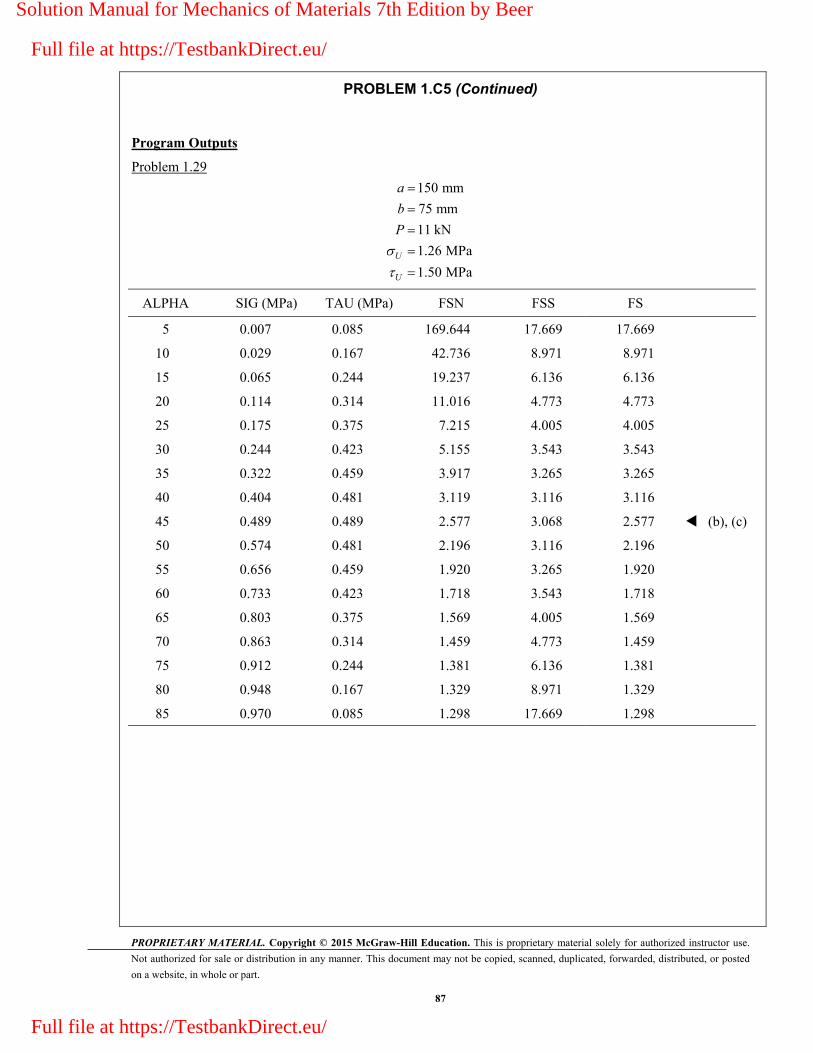
PROPRIETARY MATERIAL. Copyright © 2015 McGraw-Hill Education. This is proprietary material solely for authorized instructor use.
Not authorized for sale or distribution in any manner. This document may not be copied, scanned, duplicated, forwarded, distributed, or posted
on a website, in whole or part.
87
PROBLEM 1.C5 (Continued)
Program Outputs
Problem 1.29
150 mm
75 mm
11 kN
1.26 MPa
1.50 MPa
U
U
a
b
P
ALPHA SIG (MPa) TAU (MPa) FSN FSS FS
5 0.007 0.085 169.644 17.669 17.669
10 0.029 0.167 42.736 8.971 8.971
15 0.065 0.244 19.237 6.136 6.136
20 0.114 0.314 11.016 4.773 4.773
25 0.175 0.375 7.215 4.005 4.005
30 0.244 0.423 5.155 3.543 3.543
35 0.322 0.459 3.917 3.265 3.265
40 0.404 0.481 3.119 3.116 3.116
45 0.489 0.489 2.577 3.068 2.577 (b), (c)
50 0.574 0.481 2.196 3.116 2.196
55 0.656 0.459 1.920 3.265 1.920
60 0.733 0.423 1.718 3.543 1.718
65 0.803 0.375 1.569 4.005 1.569
70 0.863 0.314 1.459 4.773 1.459
75 0.912 0.244 1.381 6.136 1.381
80 0.948 0.167 1.329 8.971 1.329
85 0.970 0.085 1.298 17.669 1.298
Solution Manual for Mechanics of Materials 7th Edition by Beer
Full file at https://TestbankDirect.eu/
Full file at https://TestbankDirect.eu/
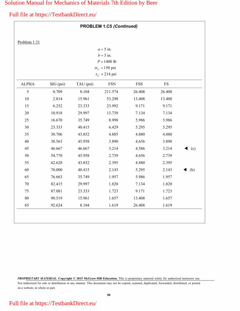
PROPRIETARY MATERIAL. Copyright © 2015 McGraw-Hill Education. This is proprietary material solely for authorized instructor use.
Not authorized for sale or distribution in any manner. This document may not be copied, scanned, duplicated, forwarded, distributed, or posted
on a website, in whole or part.
88
PROBLEM 1.C5 (Continued)
Problem 1.31
5 in.
3 in.
1400 lb
150 psi
214 psiU
U
a
b
P
ALPHA SIG (psi) TAU (psi) FSN FSS FS
5 0.709 8.104 211.574 26.408 26.408
10 2.814 15.961 53.298 13.408 13.408
15 6.252 23.333 23.992 9.171 9.171
20 10.918 29.997 13.739 7.134 7.134
25 16.670 35.749 8.998 5.986 5.986
30 23.333 40.415 6.429 5.295 5.295
35 30.706 43.852 4.885 4.880 4.880
40 38.563 45.958 3.890 4.656 3.890
45 46.667 46.667 3.214 4.586 3.214 (c)
50 54.770 45.958 2.739 4.656 2.739
55 62.628 43.852 2.395 4.880 2.395
60 70.000 40.415 2.143 5.295 2.143 (b)
65 76.663 35.749 1.957 5.986 1.957
70 82.415 29.997 1.820 7.134 1.820
75 87.081 23.333 1.723 9.171 1.723
80 90.519 15.961 1.657 13.408 1.657
85 92.624 8.104 1.619 26.408 1.619
Solution Manual for Mechanics of Materials 7th Edition by Beer
Full file at https://TestbankDirect.eu/
Full file at https://TestbankDirect.eu/

PROPRIETARY MATERIAL. Copyright © 2015 McGraw-Hill Education. This is proprietary material solely for authorized instructor use.
Not authorized for sale or distribution in any manner. This document may not be copied, scanned, duplicated, forwarded, distributed, or posted
on a website, in whole or part.
89
180 mm200 mm
Top view
Side viewFront view
8 mm
20 mm8 mm
8 mm
12 mm
12 mm
B CB
D D
A
B CA
P
PROBLEM 1.C6
Member ABC is supported by a pin and bracket at A and by two links, which are pin-connected to the member at B and to a fixed support at D. (a) Write a computer program to calculate the allowable load allP for any given values of (i) the diameter 1d of the pin at A, (ii) the common diameter d2 of the pins at B and D, (iii) the ultimate normal stress U in each of the two links, (iv) the ultimate shearing stress U in each of the three pins, and (v) the desired overall factor of safety F.S. (b) Your program should also indicate which of the following three stresses is critical: the normal stress in the links, the shearing stress in the pin at A, or the shearing stress in the pins at B and D. (c) Check your program by using the data of Probs. 1.55 and 1.56, respectively, and comparing the answers obtained for Pall with those given in the text. (d) Use your program to determine the allowable load Pall, as well as which of the stresses is critical, when 1 d
2 15 mm,d 110 MPa U for aluminum links, 100 MPa U for steel pins, and F.S. 3.2.
SOLUTION
(a) F.B. diagram of ABC:
2000:
380200
0:180
A BD
B A
M P F
M P F
(i) 1For given of Pin :d A 212( / )( /4),A UF FS d 1
200
180 AP F
(ii) 2For given of Pins and :d B D 222( / )( /4) ,BD UF FS d 2
200
380 BDP F
(iii) For ultimate stress in links BD: 3200
2( / )(0.02)(0.008) ,380
BD U BDF FS P F
(iv) For ultimate shearing stress in pins: 4P is the smaller of 1P and 2.P
(v) For desired overall F.S.: 5P is the smaller of 3P and 4.P
If 3 4< ,P P stress is critical in links.
If 4 3<P P and 1 2< ,P P stress is critical in Pin A.
If 4 3P P and 2 1,P P stress is critical in Pins B and D.
Solution Manual for Mechanics of Materials 7th Edition by Beer
Full file at https://TestbankDirect.eu/
Full file at https://TestbankDirect.eu/
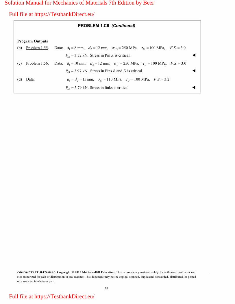
PROPRIETARY MATERIAL. Copyright © 2015 McGraw-Hill Education. This is proprietary material solely for authorized instructor use.
Not authorized for sale or distribution in any manner. This document may not be copied, scanned, duplicated, forwarded, distributed, or posted
on a website, in whole or part.
90
PROBLEM 1.C6 (Continued)
Program Outputs
(b) Problem 1.55. Data: 1 28 mm, 12 mm, , 250 MPa, 100 MPa, . . 3.0U Ud d F S
all 3.72 kN.P Stress in Pin A is critical.
(c) Problem 1.56. Data: 1 210 mm, 12 mm, 250 MPa, 100 MPa, . . 3.0 U Ud d F S
all 3.97 kN.P Stress in Pins B and D is critical.
(d) Data: 1 2 15mm, 110 MPa, 100 MPa, . . 3.2U Ud d F S
all 5.79 kN.P Stress in links is critical.
Solution Manual for Mechanics of Materials 7th Edition by Beer
Full file at https://TestbankDirect.eu/
Full file at https://TestbankDirect.eu/