Embed Size (px)
Citation preview

8/12/2019 Chapter 06(4)
http://slidepdf.com/reader/full/chapter-064 1/29
6 QUALITY CONTROL PROCEDURES
Producer PersonnelManagement RepresentativeCertified Asphalt TechniciansQualified Technicians
Reference Publications
Field Laboratory
Test Equipment Calibration
Diary
Materials SamplingAggregate/RAP SamplingBinder SamplingMixture SamplingMixture Sample Reduction
Materials TestingAggregate TestingMixture Testing
Frequency of Tests
QC/QA HMA and SMAHMA
Adjustment Period – QC/QA HMA and SMA

8/12/2019 Chapter 06(4)
http://slidepdf.com/reader/full/chapter-064 2/29
Control Charts -- QC/QA HMA and SMAApplicationControl LimitsTarget Mean ValuesControl Chart ConstructionChart Interpretation
Response to Test ResultsControl ChartsMoisture Content
Volumetric Control
VMAAir Voids
Mixture Troubleshooting
Quality Control PlanAddenda
Certification

8/12/2019 Chapter 06(4)
http://slidepdf.com/reader/full/chapter-064 3/29
6-1
CHAPTER SIX:QUALITY CONTROL PROCEDURES
The foundation for a successful Quality Assurance program is the qualitycontrol maintained by the Producer to assure that all materials submitted foracceptance conform to the contract requirements. To accomplish this, theProducer is required to have a functional plan to keep the process in control,quickly determine when the process goes out of control, and respondadequately to bring the process back into control.
This section includes the minimum requirements of the Indiana CertifiedHot Mix Asphalt Producer Program (Program) in accordance with ITM 583 .The mixtures included in this Program include QC/QA HMA in accordancewith Section 401 , HMA in accordance with Section 402 , and Stone MatrixAsphalt (SMA) in accordance with Section 410 .
PRODUCER PERSONNEL
The Producer personnel required include a Management Representative anda Certified Asphalt Technician.
Management Representative
The Management Representative is responsible for all aspects of productionand control required by the Certified Hot Mix Asphalt Producer Program ateach Certified Plant.
Certified Asphalt Technicians
A Certified Asphalt Technician is a Producer or Consultant employee whohas been certified by INDOT. The Certified Asphalt Technician compactsand determines the bulk specific gravity of the Superpave gyratoryspecimens and conducts the maximum specific gravity test. The Techniciansupervises all other sampling and testing of materials, the maintenance ofcontrol charts, and the maintenance of the diary.
Qualified Technicians
All sampling and testing used for acceptance of materials is required to beconducted by a Qualified Technician. A Qualified Technician is anindividual who has successfully completed the written and proficiencytesting requirements of the INDOT Qualified Laboratory and TechnicianProgram. Certified Asphalt Technicians are not required to take the writtenexam of this Program.
8/12/2019 Chapter 06(4)
http://slidepdf.com/reader/full/chapter-064 4/29
6-2
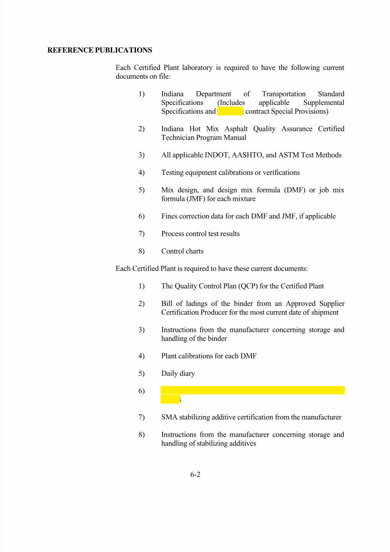
REFERENCE PUBLICATIONS
Each Certified Plant laboratory is required to have the following currentdocuments on file:
1) Indiana Department of Transportation StandardSpecifications (Includes applicable SupplementalSpecifications and pertinent contract Special Provisions)
2) Indiana Hot Mix Asphalt Quality Assurance CertifiedTechnician Program Manual
3) All applicable INDOT, AASHTO, and ASTM Test Methods
4) Testing equipment calibrations or verifications
5) Mix design, and design mix formula (DMF) or job mixformula (JMF) for each mixture
6) Fines correction data for each DMF and JMF, if applicable
7) Process control test results
8) Control charts
Each Certified Plant is required to have these current documents:
1) The Quality Control Plan (QCP) for the Certified Plant
2) Bill of ladings of the binder from an Approved SupplierCertification Producer for the most current date of shipment
3) Instructions from the manufacturer concerning storage andhandling of the binder
4) Plant calibrations for each DMF
5) Daily diary
6) Annual calibrations of the Plant scales and verification ofmeters
7) SMA stabilizing additive certification from the manufacturer
8) Instructions from the manufacturer concerning storage andhandling of stabilizing additives

8/12/2019 Chapter 06(4)
http://slidepdf.com/reader/full/chapter-064 5/29
6-3
FIELD LABORATORY
A laboratory is required to be provided and maintained at the plant site withthe necessary equipment and supplies for conducting quality control testing.An electronic balance readable to 0.1g and accurate to 0.2g or 0.1% of the
test load, whichever is greater, is required. Also, the gyratory compactor isrequired to tilt the specimen mold at an internal angle of 1.16 ± 0.02º inaccordance with AASHTO PP 48.
Performance of quality control tests at laboratory facilities other than the plant-site laboratory are allowed provided the laboratory facilities are owned by the Producer, all test procedure criteria are satisfied, and the test resultsare furnished in writing to the plant-site laboratory within two working days.INDOT is allowed access to inspect any laboratory used for quality controltesting and to witness quality control activities.
TEST EQUIPMENT CALIBRATION The equipment furnished for testing is required to be properly calibrated andmaintained within the calibration limits described in the applicable testmethod. A record of calibration results is maintained at the field laboratoryfor the equipment listed in Figure 6-1.
Figure 6-1. Equipment Calibration Requirements
Equipment Requirement MinFreq Procedure
Balances Verification 12 mo. ITM 910Gyratory Compactor Verification 1 mo. ITM 908Gyratory CompactorInternal Angle Verification 12 mo. AASHTO PP 48Gyratory HeightGage Blocks Verification 24 mo. Manufacturer
RecommendationGyratory Load Cell& Proving Ring Calibrate 24 mo. Manufacturer
RecommendationGyratory Mold andPlate Dimensions Verification 12 mo. ITM 913
Ignition Oven Conduct Lift Test Weekly OperatorsManual
Mechanical Shakers Verify Sieving Thoroughness 12 mo. ITM 906
Ovens Verify Temperature Settings 6 mo. ITM 903Sieves Verify Physical Condition 6 mo. ITM 902Thermometers Verification 6 mo. ITM 909Vacuum Gage Calibrate 36 mo. Manufacturer
RecommendationVacuum Pump Verify Pressure 12 mo. ITM 905Vacuum Chamber Verification 3 mo. ITM 905Volumetric Flask Calibrate 1 mo. AASHTO T 209

8/12/2019 Chapter 06(4)
http://slidepdf.com/reader/full/chapter-064 6/29
6-4
DIARY
The Producer is required to maintain a diary at the Certified Plant. The diaryis an open format book with at least one page devoted to each day mixture is
produced. The diary is kept on file for a minimum period of three years.
Entries in the diary include at least the following:
1) The quantity of mixture produced, DMF or JMF, and thecontract number or purchase order for each mixture
2) The time that the samples were obtained and the time the testwas completed
3) Nonconforming tests and the resulting corrective action taken
4)
Any significant events or problemsThe diary entry is to be routinely signed by the Certified Asphalt Technicianor Management Representative. On occasion the diary may be signed byanother person; however, the diary is required to be counter-signed by theCertified Asphalt Technician or Management Representative.
MATERIAL SAMPLING
The Producer is required to designate the sampling and sample reduction procedures, sampling location, and size of samples necessary for testing.Sampling is conducted on uniform tonnage increments on a random basis.
AGGREGATE/RAP SAMPLING
Aggregate samples may be obtained from stockpiles, belts, or hot binsdepending on the type of plant and control of aggregate gradation selected.The procedures for these methods of sampling are described in Chapter 2. IfRAP is used in the mixture, the procedure for sampling this material is ITM207 .
BINDER SAMPLING
Two one quart samples are obtained from either the Certified Plant bindertank or injection line in accordance with AASHTO T 40 . The procedure forsampling binder is described in Chapter 3.

8/12/2019 Chapter 06(4)
http://slidepdf.com/reader/full/chapter-064 7/29
6-5
MIXTURE SAMPLING
The most important consideration in sampling mixture is to be certain thatthe sample taken is representative of the material being produced. Thesampling procedures for mixture are included in ITM 580 . For trucksampling, a square bit shovel of the appropriate size for the required sampleis used. For plate sampling, a metal square plate with a minimum size of 8in. is used. Procedures for truck sampling and pavement sampling areexplained as follows:
Truck Sampling – 4.75 mm Mixtures
1) The mixture in the truck is visually observed fordetermination of uniformity.
2) The shovel is inserted into the the mixture at variouslocations that appear uniform in texture, and the mixture is
placed into a sample container.
Truck Sampling -- Dense Graded Mixtures
1) The shovel is inserted horizontally into the mixture at theapproximate mid section of the truck.
2) The shovel is lifted vertically to establish a horizontal planein the mixture.
3) The shovel is inserted vertically to establish a vertical face
below the horizontal plane.
4) The shovel is inserted horizontally into the vertical face at adepth of approximately twice the thickness of the maximum
particle size of the material.
5) The shovel is lifted vertically to obtain the sample, and thesample is placed into a sample container.
Truck Sampling – Open Graded Mixtures
1) The shovel is inserted into the mixture between the centerof the cone and the front of the truck to obtain one sample.
2) Another sample is obtained with the shovel from the mixture between the center of the truck and the back of the truck.
3) The two samples are combined.

8/12/2019 Chapter 06(4)
http://slidepdf.com/reader/full/chapter-064 8/29
6-6
Pavement Sampling -- Plate
1) A clean metal plate with attached wire is placed on the pavement. Should conditions on the contract requirestabilizing movement to avoid slipping of the plate, a nail isdriven into the pavement, and the plate hole placed onto thenail. A No. 18 gage mechanics wire and masonry nail has
proven to be effective for this purpose.
2) The wire is extended beyond the edge of the paving width.The wire should not pass under a grade leveler attached to the
paver. Trucks, pavers, or material transfer devices areallowed to cross the plate and/or wire. If a windrow elevatoris used, the paving operation is stopped so that the plate may
be placed between the windrow elevator and the paver.
3) After the mixture is placed and before any compaction fromthe rollers occurs, the wire is used to locate the plate.
4) The plate is lifted with the wire, a narrow shovel or pitchforkis inserted under the plate, and the plate is lifted from the
pavement.
5) The sample is then placed in a container for transport to thetesting facility. Material remaining on the plate is required to
be removed and placed into the sample container.
Pavement Sampling -- Plate with a Mold
The placement and location of the plate are done using the same proceduresand restrictions used for sampling when only a plate is used. Additionalrequirements for using a mold with a plate include:
1) A clean round mold, with a height greater than the mixturethickness and diameter less than the width of the plate, is
pushed by means of a circular motion down into the mixturedirectly over the plate.
2) The mold and plate are raised together and a pitchfork ornarrow shovel is inserted under the plate.
3) The mold and plate are lifted from the pavement and anyexcess mixture on top of the plate and outside of the mold isdiscarded.
4) The sample inside the mold is placed into the samplecontainer. Material remaining on the plate is removed and
placed into the sample container.

8/12/2019 Chapter 06(4)
http://slidepdf.com/reader/full/chapter-064 9/29
6-7
MIXTURE SAMPLE REDUCTION
Once the sample is obtained, the next step required is to reduce the sample tothe appropriate test size. The sample reduction procedures are included inITM 587 . Sample reduction to meet a minimum weight, a weight range, anda target weight are as follows:
Minimum Weight -- HMA Extraction, Maximum Specific Gravity, and Bulk SpecificGravity
1) The sample is placed on a clean splitting board andthoroughly mixed with a trowel or dry wall taping knife.
2) The sample is then quartered into four approximately equal portions, the diagonally opposite quarters are combined, andthe sample weighed.
3) If the sample weight does not meet the minimum weightrequirement of the appropriate test method, the sample is setaside and the remaining mixture is recombined, mixed, andquartered again.
4) The diagonally opposite quarters of the recombined mixtureare added to the sample that was set aside. This procedure isrepeated until the appropriate test size is obtained.
5) If the sample after combining the diagonally oppositequarters of the original sample is excessively large, thesample may be discarded. The remaining mixture isrecombined and quartered, as indicated above, until theappropriate size of sample is obtained.
Weight Range -- Ignition Oven
The procedure for reducing a sample for testing using the ignition oven isdifferent than the above procedure because the sample size is required to bewithin a weight range. The procedure is as follows:
1) The sample is placed on a clean splitting board and
thoroughly mixed with a trowel or dry-wall taping knife.
2) The sample is then quartered into four approximately equal portions, the diagonally opposite quarters are combined, andthe sample is weighed.

8/12/2019 Chapter 06(4)
http://slidepdf.com/reader/full/chapter-064 10/29
6-8
3) If the sample weight does not meet the minimum weightrequirement for the ignition test, the sample is set aside, andthe remaining mixture is recombined, mixed, and quarteredagain.
4) The diagonally opposite quarters of the recombined mixtureare added to the sample that was set aside.
5) If the total sample weight is less than the required minimumweight, the quartering procedure is repeated with theremaining mixture until a proper weight is obtained.
6) If the sample, after combining the diagonally oppositequarters of the additional mixture to the original sample,exceeds the maximum weight requirement for the ignition
test, the additional sample is discarded and the quartering procedure as noted above is continued for the remainingmixture until the proper weight is obtained.
Target Weight – Gyratory Specimens
The procedure for reducing a sample to fabricate a specimen with thegyratory compactor requires that an exact weight be obtained as designatedon the DMF/JMF to obtain the correct height of the specimen. The
procedure is as follows:
1) The sample is placed on a clean splitting board
2) The sample is thoroughly mixed with a trowel or dry-walltaping knife and quartered into four approximately equal
portions
3) Two diagonally opposite portions are combined and thesample weighed (Note 1). This sample will initially beused to prepare Specimen A.
Note 1: The sample will generally exceed the target weight by more than 300 g after the first split. Weighing thesample is not required when the sample obviously exceedsthe target weight. The remaining portions from the initialsplit are set aside for later use in Specimen B.

8/12/2019 Chapter 06(4)
http://slidepdf.com/reader/full/chapter-064 11/29
6-9
4) If the sample is greater than the target weight and notwithin 300 g of the target, steps 2 and 3 are repeated on thesample. When the sample becomes less than the targetweight by more than 300 g, step 5 is done next. If the
sample is within + 300 g of the target weight, step 6 or 7 isused depending on whether the sample is less than orgreater than the target weight.
5) If the sample is less than the target weight and not within300 g of the target, the sample is set aside and steps 2 and 3are repeated on the remaining portions. The diagonallyopposite portions are added to the previously weighedsample until the sample is within + 300 g of the targetweight (Note 2). Step 6 or step 7 is done next.
Note 2: Exceeding the target weight by more than 300 gshould be avoided. If in doubt, the diagonally opposite portions should be weighed prior to adding to the previously weighed sample to avoid exceeding the targetweight. If the target weight has been exceeded by 300 g,the procedure should be started over.
6) For samples less than and within 300 g of the target weight,the remaining quarters are mixed into a miniature stockpile.An amount required for achieving the target weight iscarefully added to the sample by sampling with a trowel ata location approximately one-third the stockpile height,measured from the base of the stockpile. The target weightis considered obtained when the weight is within + 10 g ofthe DMF/JMF target weight value.
7) For samples more than and within 300 g of the targetweight, the sample is mixed into a miniature stockpile. Anamount required for achieving the target weight is carefullyremoved from the sample by sampling with a trowel at alocation approximately one-third the stockpile height,measured from the base of the stockpile.
8) The remnant material from Specimen A is discarded andthese procedures are repeated on material saved from theinitial split for use in Specimen B.

8/12/2019 Chapter 06(4)
http://slidepdf.com/reader/full/chapter-064 12/29
6-10
MATERIALS TESTING
The Producer is required to designate the testing procedures to be used forcontrol of the aggregates, RAP, and mixture. Testing is required to be
completed within two working days of the time the sample was taken. TheProducer is required to keep the test results on file for a minimum period ofthree years.
AGGREGATE TESTING
Gradation
Gradations done on blended aggregate or aggregate stockpile samples areconducted using AASHTO T 27 . If RAP is used in the mixture, the test
procedure for the gradation is AASHTO T 30 .
Moisture Content
AASHTO T 255 is the test procedure used for determination of the totalmoisture content of the cold feed belt or belt discharge aggregate samples fora drum plant.
MIXTURE TESTING
The analysis of the mixture to meet the requirements of the Program includesseveral tests. Detailed procedures of these tests are included in appendices Aand B and include:
Mixture Calibration
A plant calibration is required to be made for each mixture to be produced inaccordance with the following methods:
Batch Plants -- the percentage of the total aggregate to be obtainedfrom each hot bin and the RAP belt
Drum Plants -- the percentage of the total aggregate to be obtainedfrom each cold bin and the RAP bin
Moisture Content
ITM 572 outlines the procedure for determination of the moisture content.Of particular importance is that the sample be placed immediately into anoven bag when obtaining the sample so that an accurate moisture contentmay be obtained.

8/12/2019 Chapter 06(4)
http://slidepdf.com/reader/full/chapter-064 13/29
6-11
Binder Content
Several methods are allowed for determination of the binder content;however, the Ignition Method ( ITM 586 ) and the Extraction Method ( ITM571 ) are the most common procedures.
Extracted Aggregate Gradation
After the binder content has been determined in accordance with ITM 571 ,the sieve analysis of the aggregate is made using AASHTO T 30 , except thedecantation through the No. 200 sieve is not required. If the Ignition Oven isused, the aggregate sample is first decanted and then the sample is sieved inaccordance with AASHTO T 30 .
Coarse Aggregate Angularity
If gravel is used in the mixture or the RAP contains gravel, the coarseaggregate angularity (crushed content) is determined after the sieve analysis.ASTM D 5821 is the procedure used for determination of both one and twofaced crushed particles.
Mixture Specimen Preparation
Specimens to determine the air voids and VMA are compacted to Ndes inaccordance with AASHTO T 312 . The compaction temperature is 300 ±9°F for dense graded mixtures and SMA, and 260 ± 9°F for open gradedmixtures.
Bulk Specific Gravity
AASHTO T 166 is the procedure used for determination of the bulk specificgravity of the gyratory specimens for dense graded and SMA mixtures. The
bulk specific gravity of the gyratory specimens for open graded mixtures,OG 19.0 and OG 25.0, is determined in accordance with AASHTO T 331 .
Maximum Specific Gravity
AASHTO T 209 is the procedure used for determination of the maximumspecific gravity of the mixture. The supplemental procedure for mixturescontaining porous aggregates may be required if the aggregate absorbs waterduring the test.
Draindown
AASHTO T 305 is the procedure used to determine the amount of binderthat drains from the mixture during production. This is a requirement foropen graded mixtures and SMA.

8/12/2019 Chapter 06(4)
http://slidepdf.com/reader/full/chapter-064 14/29
6-12
Temperature
The best procedure to determine the temperature of the mixture is with a dialand armored-stem thermometer. The stem is required to be insertedsufficiently deep (at least 6 in.) into the mixture, and the material is requiredto be in direct contact with the stem.
The gun-type infrared thermal meter, which measures reflective heat fromthe surface, may also be used. This device detects only surface heat and maynot be accurate for material within the truck. To overcome this problem, theinstrument may be directed at the stream of mixture at the discharge gate ofthe mixer or surge bin.
FREQUENCY OF TESTS
QC/QA HMA and SMA
The frequency of tests is determined by the Producer and is required to beincluded in the QCP for the following items:
1) Aggregatesa) Stockpiles
b) Blended Aggregate
2) Binder
3) Recycled Materialsa) Binder Content
b) Gradationc) Moisture Contentd) Coarse Aggregate Angularity
4) Mixture Sampled at the HMA planta) Binder Content
b) Gradation (for SMA mixtures only)c) Moisture Contentd) Temperaturee) Draindown (for open graded and SMA mixtures
only)
5) Mixture Sampled from the Pavementa) Air Voids
b) VMAc) Actual Binder Contentd) Gradation (for SMA mixtures only)e) Moisture (for surface mixtures only)f) Bulk Specific Gravityg) Maximum Specific Gravity

8/12/2019 Chapter 06(4)
http://slidepdf.com/reader/full/chapter-064 15/29
6-13
HMA
HMA mixture produced concurrently with QC/QA HMA mixture is requiredto be sampled and tested in accordance with the requirements established forQC/QA HMA. All other HMA is required to be sampled at the HMA plantor the roadway and tested for binder content, coarse aggregate angularity formixtures containing gravel, gradation, and air voids in accordance with thefollowing minimum frequency:
1) The first 250 tons and each subsequent 1000 tons of eachDMF or JMF in a construction season for base andintermediate mixtures
2) The first 250 tons and each subsequent 600 tons of eachDMF or JMF in a construction season for surface mixtures
ADJUSTMENT PERIOD – QC/QA HMA and SMA
The Producer is allowed an adjustment period for each DMF in whichchanges may be made. The adjustment period is from the beginning of
production and extending until 5000 tons of base and intermediate mixturesor 3000 tons of surface mixture has been produced. A reduced adjustment
period may be allowed. A JMF is established after the adjustment period.The following adjustments are allowed:
1) The amount passing all sieves on the DMF may be adjusted provided the gradation limits and the dust/calculated effective binder ratio do not exceed the requirements of Section 401.05 for QC/QA HMA, and the gradation limits do not exceed therequirements of Section 410.05 for SMA mixtures.
2) The binder content on the JMF for QC/QA HMA may beadjusted ± 0.5 percent provided the dust/calculated effective
binder ratio is in accordance with Section 401.05 .
3) The VMA on the JMF for QC/QA HMA may be adjusted provided the new value is in accordance with Section 401.05 .
4) The air voids and VMA for open graded mixtures may beadjusted from the DMF provided the new value is inaccordance with Section 401.05 .
If an adjustment is necessary, a JMF is submitted in writing for approval tothe District Testing Engineer one working day after the receipt of the testresults for the binder content, VMA, and air voids of the adjustment period.The JMF is required to include the adjusted gradation, binder content orVMA, unit weight at N des, and the dust/calculated effective binder ratio, ifapplicable.

8/12/2019 Chapter 06(4)
http://slidepdf.com/reader/full/chapter-064 16/29
6-14
Only one adjustment period is allowed for each DMF within a constructionseason. If production extends into the next construction season, the DMF isallowed another adjustment period. If a JMF was approved, the adjustmentsare made from the JMF.
CONTROL CHARTS -- QC/QA HMA and SMA
A control chart is a graphic representation of data shown with prescribedlimits that indicate whether a process is in control. Timely reaction to thecontrol chart may prevent the production of nonconforming material.
Control charts are maintained by the Producer at the Certified Plantlaboratory. All test results are recorded on the control charts the same daythe tests are conducted. As a minimum the charts are maintained until 30test data points have been plotted. Subsequent to that time at least 30 test
data points are continuously displayed. All charts are required to be retained by the Producer for the Certified Plant for a period of three years.
APPLICATION
As a minimum, control charts are required for each QC/QA HMA and SMAmixture as follows:
1) Binder content of the mixture for each DMF and JMF
2) Air voids for each DMF and JMF
3) VMA for each DMF and JMF for dense graded mixture andSMA
CONTROL LIMITS
The control limits from the target mean value are required to be plotted onthe control charts for Binder Content, Air Voids, and VMA and may be
plotted on the control charts for all others as shown in Figure 6-2.

8/12/2019 Chapter 06(4)
http://slidepdf.com/reader/full/chapter-064 17/29
6-15
Parameter Control LimitsAggregate Stockpile Samples,Max. % Passing Sieves
3/4 in.1/2 in. No. 4 No. 8
No. 16 No. 30 No. 50
No. 100 No. 200
± 10.0± 10.0± 10.0± 10.0± 8.0± 6.0± 6.0± 6.0± 2.0
Blended Aggregate, Max. % Passing SieveBase and Intermediate Mixtures
3/4 in.1/2 in. No. 4 No. 8
No. 16 No. 30 No. 50
No. 100 No. 200
± 10.0± 10.0± 10.0± 10.0± 8.0± 6.0± 6.0± 6.0± 2.0
Blended Aggregate, Max. % Passing SieveSurface Mixtures
1/2 in. No. 4 No. 8
No. 16 No. 30 No. 50
No. 100 No. 200
± 10.0± 10.0± 8.0± 8.0± 4.0± 4.0± 3.0± 2.0
Binder Content of Mixture, % ± 0.7VMA @ N des, % (QC/QA HMA) ± 1.0VMA @ N 100, Min. % (SMA) 17Air Voids @ Ndes, %(Dense Graded Mixtures and SMA) ± 1.0
Air Voids, %(Open Graded Mixtures) ± 3.0
Figure 6-2. Control Limits

8/12/2019 Chapter 06(4)
http://slidepdf.com/reader/full/chapter-064 18/29
6-16
TARGET MEAN VALUES
The target mean values are required to be as follows:
Binder Content -- the value indicated on the JMF
Air Voids -- the value designated by the Producer
Voids in Mineral Aggregate -- the value indicated on the JMF
CONTROL CHART CONSTRUCTION
The control chart is required to be plotted in accordance with specificrequirements. Any proposed deviation of the procedures is required to beclearly identified in the QCP. The requirements are as follows:
1) The target mean value is represented by a heavy long dashfollowed by a short dash line
2) Control limits are represented by heavy solid lines
3) The placement of the horizontal lines for the control limitsand target mean value are numerically identified in the leftmargin;
4) The plot point for the test results is surrounded by a smallcircle and each consecutive point is connected by a solidstraight line
5) The moving average of the most current test values isindicated by a small triangle symbol and connected bystraight lines
6) The test results are plotted left to right in chronological orderand dates corresponding to each test are shown along thehorizontal axis
7) All values are plotted to the nearest 0.1 percent
Test results for samples obtained from other than at the Certified Plant may be plotted on the corresponding chart provided the points are not connectedwith the test results from the Certified Plant and the test results are notincluded in the moving average. An example of a control chart is shown inFigure 6-3.

8/12/2019 Chapter 06(4)
http://slidepdf.com/reader/full/chapter-064 19/29
6-17
Figure 6-3. Control Chart
8/12/2019 Chapter 06(4)
http://slidepdf.com/reader/full/chapter-064 20/29
6-18
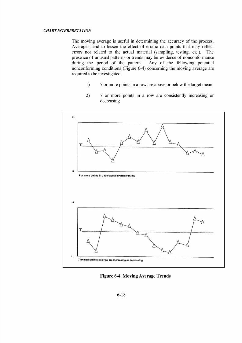
CHART INTERPRETATION
The moving average is useful in determining the accuracy of the process.Averages tend to lessen the effect of erratic data points that may reflecterrors not related to the actual material (sampling, testing, etc.). The
presence of unusual patterns or trends may be evidence of nonconformanceduring the period of the pattern. Any of the following potentialnonconforming conditions (Figure 6-4) concerning the moving average arerequired to be investigated.
1) 7 or more points in a row are above or below the target mean
2) 7 or more points in a row are consistently increasing ordecreasing
Figure 6-4. Moving Average Trends

8/12/2019 Chapter 06(4)
http://slidepdf.com/reader/full/chapter-064 21/29
6-19
RESPONSE TO TEST RESULTS
CONTROL CHARTS
The Producer is required to take corrective action when the control limits forQC/QA HMA and SMA or Specification Limits for HMA mixtures areexceeded for the appropriate properties of binder content of the mixture, airvoids, and VMA. Corrective action includes, but is not limited to,investigation for assignable cause, correction of known assignable cause, orretesting.
MOISTURE CONTENT
The Producer is required to take corrective action when the moisture contentof the mixture exceeds 0.3 percent for samples taken at the plant, or whenthe moisture content of the surface mixture sampled from the pavementexceeds 0.10 percent.
VOLUMETRIC CONTROL
Verification of the volumetric mixture properties is one of the mostimportant duties of the Technician. Changes in the material or control at theHMA plant may result in the air voids and VMA falling outside of theSpecification limits. The general trend is that the design air voids and VMAwill decrease during production at the plant. This section containsinformation concerning the steps that may be taken to correct a deficientvolumetric property. In order to use these guidelines, the mixturecompositionis required to be reasonably close to the designed mixture.
VMA
Figure 6-5 is a flow chart for VMA adjustment for plant - produced mixture.The amount of material passing the No. 200 sieve and the relative
proportions of coarse and fine aggregate may significantly affect the VMA.A loss of VMA is a common problem during production.

8/12/2019 Chapter 06(4)
http://slidepdf.com/reader/full/chapter-064 22/29
6-20
Figure 6-5. VMA Adjustment Process

8/12/2019 Chapter 06(4)
http://slidepdf.com/reader/full/chapter-064 23/29
6-21
Gradation changes may be caused by a mechanical problem with the plant.A comparison of the blended aggregate and extracted aggregate gradations isa good technique to verify if this problem exists. Also, there is, in mostcases, some "rounding" of the edges of the coarse aggregate particles as they
pass through the drum. This rounding of the aggregate lowers the VMA.
Dust variation in the mixture may be caused by variations in the minus No.200 sieve material of the aggregates; however, a change in the dust is morelikely to be the result of the inconsistent return of fines from the plant
baghouse. Specifications require that if dust is returned into the mixture, thesystem is required to return the material at a constant rate during production.A check on the fines return system is required to be made to verify thisconstant rate of return of fines.
Adjusting for low VMA is the more common problem a Technician needs tocorrect. Procedures for increasing the VMA include:
1) Reduce the amount of material passing the No. 200 sieve
2) Reduce the amount of natural sand in the mixture
3) Adjust the aggregate gradation away from the MaximumDensity Line
AIR VOIDS
Figure 6-6 is a flow chart for adjusting air voids for plant-produced mixture.Air voids are influenced by a combination of VMA, percent passing the No.200 sieve, and the binder content. Adjustments of the air voids is dependenton the magnitude of the variance between the production and JMF values. Ifthe difference is greater than 0.5 percent, consideration should be given toadjusting the binder content; if the difference is less than 0.5 percent, the
percent passing the No. 200 sieve may be adjusted.
A comparison of the production bulk specific gravity (Gmb) and maximumspecific gravity (Gmm) values to the DMF and previous production valuesshould also be done. Different Gmb values may be caused by an aggregategradation change (especially the P 200) or by a particle shape change fromaggregate breakdown. Different Gmm values may be caused by a bindercontent, aggregate absorption, or aggregate specific gravity change.

8/12/2019 Chapter 06(4)
http://slidepdf.com/reader/full/chapter-064 24/29
6-22
Figure 6-6. Air Voids Adjustment Process

8/12/2019 Chapter 06(4)
http://slidepdf.com/reader/full/chapter-064 25/29
6-23
The air voids, as with the VMA, may need to be increased in most caseswhen the Specifications are not being met. Procedures for increasing the airvoids include:
1) Reduce the binder content
2) Reduce the amount passing the No. 200 sieve
3) Change the relative proportion of coarse and fine aggregate
MIXTURE TROUBLESHOOTING
Figure 6-7 lists the materials and properties that are verified at the HMA plant and the possible causes of problems with these materials. For each property, the potential problem areas are given a priority number with thenumber 1 being the area that should be checked first.
Verification of the mix design prior to production for the contract is the best procedure to prevent potential problems. By using the actual stockpiledmaterials and testing the effect the HMA plant has on those materials,adjustments may be made to the mixture to meet the requirements.
During production there are other means available to make a quickdetermination of the properties of the mixture. For volumetricdeterminations, the air voids and VMA may be approximated by estimatingthe bulk specific gravity (Gmb) of the mixture. This estimation of Gmb ismade from the height of the gyratory specimen when a constant sample massis used.

8/12/2019 Chapter 06(4)
http://slidepdf.com/reader/full/chapter-064 26/29
6-24
Figure 6-7. Mixture Troubleshooting Chart

8/12/2019 Chapter 06(4)
http://slidepdf.com/reader/full/chapter-064 27/29
6-25
QUALITY CONTROL PLAN
Each Producer providing QC/QA HMA, HMA, or SMA under the Certified HotMix Asphalt Producer Program is required to have a written QCP that is plantspecific and is the basis of control. The QCP contains, but is not limited to, the
methods of sampling, testing, calibration, verification, inspection, and anticipatedfrequencies.
The QCP includes the following information for each Certified Plant.
1) The location of the Certified Plant site, including the countyand reference to the nearest identifiable points such ashighway and towns.
2) The name, telephone number, duties, and employer of theManagement Representative and Certified Asphalt
Technician(s). The duties of all other personnel responsiblefor implementation of the QCP are also included.
3) A list of test equipment that is calibrated or verified, the testmethods and frequency of calibration or verification of theequipment, and a statement of accessibility of the laboratoryto INDOT personnel.
If the laboratory is not located at the Certified Plant, thelocation of the laboratory is required to be designated, and the
procedure for transporting the mixture to the laboratoryincluded
4) A plant site layout diagram that includes the location of thestockpile area, binder tanks, fuel tank, stabilizing additivesupply, anti-adhesive supply, field laboratory, visitor parkingarea and mixing plant.
5) A plan for controls of the aggregate and recycled materialstockpiles. Controls for identification of stockpiles bysigning or other acceptable methods, techniques forconstruction of proper stockpiles, and cold bin loading
procedures to prevent overflow of material from one bin intoanother are required to be included.
6) A plan for the identification of the grade of binder in eachstorage tank and the use of more than one binder grade in a
binder tank. The sampling location is required to beindicated.

8/12/2019 Chapter 06(4)
http://slidepdf.com/reader/full/chapter-064 28/29
6-26
7) The procedure for the consistent uniform addition of baghouse fines when returned into the mixing plant.
8) The procedure for the consistent uniform addition of
stabilizing additives into the mixing plant.
9) The procedure for using an anti-adhesive agent for the truck bed, and a statement that the agent is on the list of ApprovedAnti-Adhesive Agents.
10) The procedure for sealing the surge bin when used forextended storage of the mixture and the method to preventthe discharge when the mixture falls below the top of thecone. The written approval of the surge bin is required to beincluded.
11) The procedure for loading mixture into the trucks.
12) A sampling plan that includes locations, test methods,devices, techniques, frequencies, and splitting procedures.
13) A testing plan that includes the types of tests, and testmethods.
14) A description of any other process control techniques thatmay be used beyond the minimum required by INDOT.These controls may include, but are not limited to:
a) Different types or greater frequencies of materialtesting
b) Visual checks and monitoring of plant production
15) A statement of the procedure for handling addenda to theQCP including a time schedule for submittal.
16) A documentation plan with details on control charting, testdata, and the diary. Copies of the forms may be included.
A QCP checklist (Appendix D) is provided to assure that all the applicableitems required in ITM 583 are addressed in the QCP.

8/12/2019 Chapter 06(4)
http://slidepdf.com/reader/full/chapter-064 29/29
ADDENDA
Addenda are defined as an addition or deletion to the QCP. Each page of theQCP that is revised is required to include the HMA plant number, date ofrevision, and means of identifying the revision. The addenda are required to
be signed and dated by the Management Representative and subsequentlysigned and dated when approved by the Testing Engineer.
Revisions for HMA plant major components, Certified Asphalt Technicians,and movement of the HMA plant are submitted in the format of a QCPAnnex (Appendix D) as they occur. Upon approval by the District TestingEngineer, the QCP Annex is placed in the Appendix of the QCP until suchtime that the revisions are incorporated into the QCP.
Revisions, other than items on the QCP Annex, are maintained on anAddenda Summary Sheet. The Addenda Summary Sheet is a page of theQCP Appendix that is used to record a brief description of the revision untilsuch time that the revision is incorporated into the QCP.
Addenda may be submitted at the audit close-out meeting or within the firsttwo months of each calendar year. The addenda are required to includeitems on the QCP Annex, items on the Addenda Summary Sheet, and anyother necessary revisions at the time of submittal. Upon incorporation intothe QCP as addenda, the QCP annex and items on the Addenda SummarySheet are removed from the QCP Appendix.
CERTIFICATION
Each Producer requesting to establish a Certified Plant is required do so inwriting to the Manager, Office of Materials Management. Upon receipt ofthe request for certification, the District is notified to inspect the plant andlaboratory.
The plant inspection, including the correction of any deficiencies andcalibration of all meters, scales and other measuring devices, is required to
be completed prior to certification.
Each plant meeting the requirements of the Program is certified upon theapproval of the QCP. Movement of the Certified Plant to a new locationrequires submittal of a QCP Annex, and verification of the calibration of allmeters, scales, and other measuring devices.