Embed Size (px)
Citation preview
Karbala University College of Engineering Department of Civil Eng. Lecturer: Dr. Jawad T. Abodi
Chapter 05
Structural Steel Design
According to the AISC Manual 13th Edition
Analysis and Design of Beams
By
Dr. Jawad Talib Al-Nasrawi
University of Karbala
College of Engineering
Department of Civil Engineering
71
Karbala University College of Engineering Department of Civil Eng. Lecturer: Dr. Jawad T. Abodi
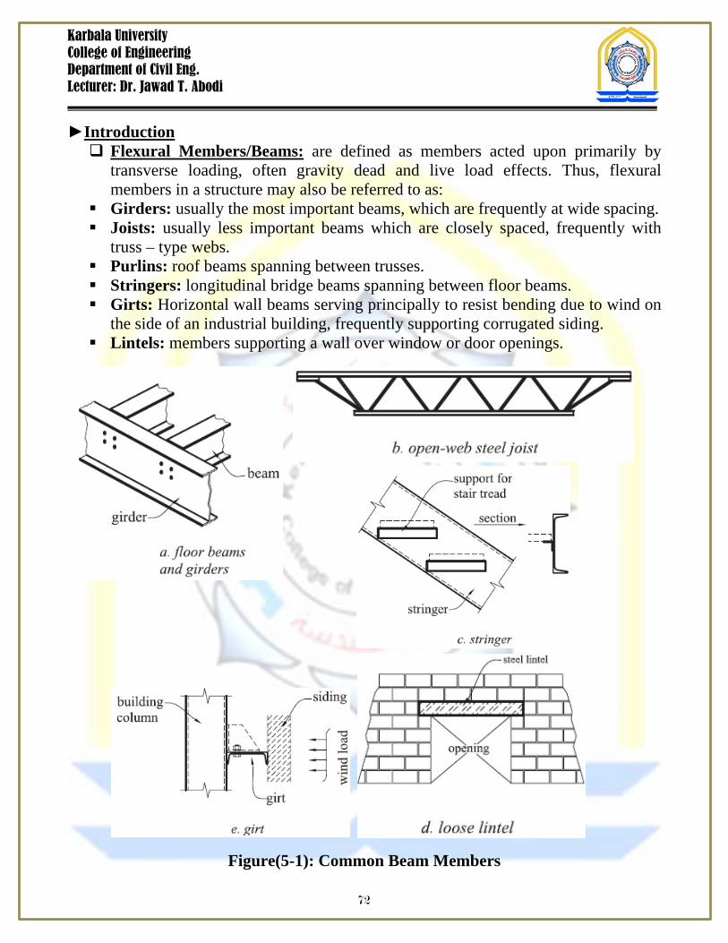
Introduction Flexural Members/Beams: are defined as members acted upon primarily by
transverse loading, often gravity dead and live load effects. Thus, flexural members in a structure may also be referred to as:
Girders: usually the most important beams, which are frequently at wide spacing. Joists: usually less important beams which are closely spaced, frequently with
truss – type webs. Purlins: roof beams spanning between trusses. Stringers: longitudinal bridge beams spanning between floor beams. Girts: Horizontal wall beams serving principally to resist bending due to wind on
the side of an industrial building, frequently supporting corrugated siding. Lintels: members supporting a wall over window or door openings.
Figure(5-1): Common Beam Members
72
Karbala University College of Engineering Department of Civil Eng. Lecturer: Dr. Jawad T. Abodi
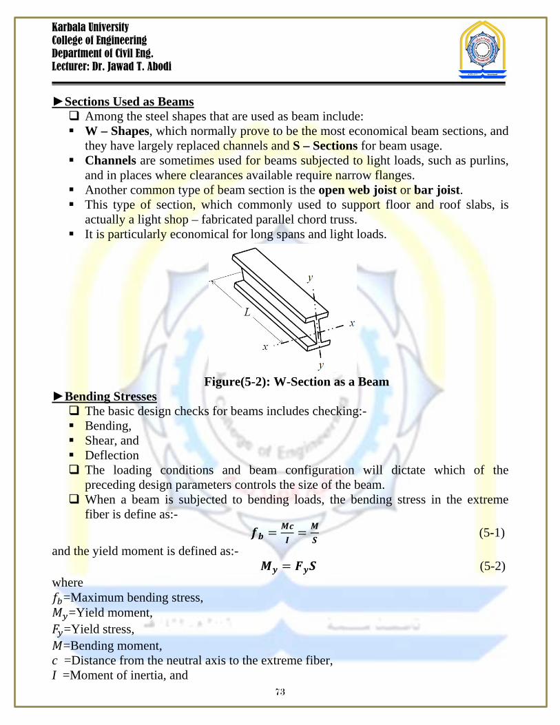
Sections Used as Beams Among the steel shapes that are used as beam include: W – Shapes, which normally prove to be the most economical beam sections, and
they have largely replaced channels and S – Sections for beam usage. Channels are sometimes used for beams subjected to light loads, such as purlins,
and in places where clearances available require narrow flanges. Another common type of beam section is the open web joist or bar joist. This type of section, which commonly used to support floor and roof slabs, is
actually a light shop – fabricated parallel chord truss. It is particularly economical for long spans and light loads.
Figure(5-2): W-Section as a Beam Bending Stresses The basic design checks for beams includes checking:- Bending, Shear, and Deflection The loading conditions and beam configuration will dictate which of the
preceding design parameters controls the size of the beam. When a beam is subjected to bending loads, the bending stress in the extreme
fiber is define as:- 𝒇𝒃 = 𝑴𝒄
𝑰= 𝑴
𝑺 (5-1)
and the yield moment is defined as:- 𝑴𝒚 = 𝑭𝒚𝑺 (5-2) where 𝑓𝑏=Maximum bending stress, 𝑀𝑦=Yield moment, 𝐹𝑦=Yield stress, 𝑀=Bending moment, c =Distance from the neutral axis to the extreme fiber, I =Moment of inertia, and
73
Karbala University College of Engineering Department of Civil Eng. Lecturer: Dr. Jawad T. Abodi
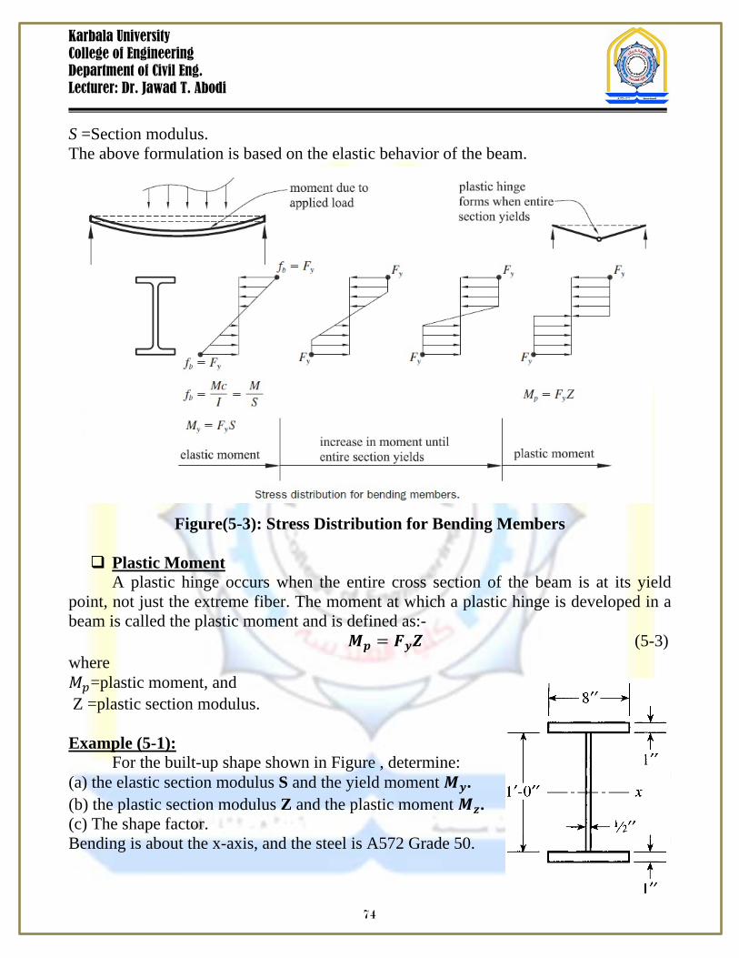
S =Section modulus. The above formulation is based on the elastic behavior of the beam.
Figure(5-3): Stress Distribution for Bending Members Plastic Moment
A plastic hinge occurs when the entire cross section of the beam is at its yield point, not just the extreme fiber. The moment at which a plastic hinge is developed in a beam is called the plastic moment and is defined as:- 𝑴𝒑 = 𝑭𝒚𝒁 (5-3) where 𝑀𝑝=plastic moment, and Z =plastic section modulus.
Example (5-1):
For the built-up shape shown in Figure , determine: (a) the elastic section modulus S and the yield moment 𝑴𝒚. (b) the plastic section modulus Z and the plastic moment 𝑴𝒛. (c) The shape factor. Bending is about the x-axis, and the steel is A572 Grade 50.
74
Karbala University College of Engineering Department of Civil Eng. Lecturer: Dr. Jawad T. Abodi
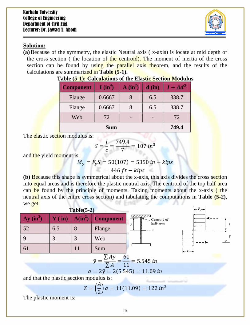
Solution: (a) Because of the symmetry, the elastic Neutral axis ( x-axis) is locate at mid depth of
the cross section ( the location of the centroid). The moment of inertia of the cross section can be found by using the parallel axis theorem, and the results of the calculations are summarized in Table (5-1).
Table (5-1): Calculations of the Elastic Section Modulus Component I (in4) A (in2) d (in) 𝑰 + 𝑨𝒅𝟐
Flange 0.6667 8 6.5 338.7
Flange 0.6667 8 6.5 338.7
Web 72 - - 72
Sum 749.4 The elastic section modulus is:
𝑆 =𝐼𝑐
=749.4
7= 107 𝑖𝑛3
and the yield moment is: 𝑀𝑦 = 𝐹𝑦𝑆 = 50(107) = 5350 𝑖𝑛 − 𝑘𝑖𝑝𝑠
= 446 𝑓𝑡 − 𝑘𝑖𝑝𝑠 (b) Because this shape is symmetrical about the x-axis, this axis divides the cross section into equal areas and is therefore the plastic neutral axis. The centroid of the top half-area can be found by the principle of moments. Taking moments about the x-axis ( the neutral axis of the entire cross section) and tabulating the computations in Table (5-2), we get: Table(5-2)
Component A(in2) Y ( in) Ay (in3)
Flange 8 6.5 52
Web 3 3 9
Sum 11 61
𝑦 =∑𝐴𝑦∑𝐴
=6111
= 5.545 𝑖𝑛
𝑎 = 2𝑦 = 2(5.545) = 11.09 𝑖𝑛 and that the plastic section modulus is:
𝑍 = 𝐴2 𝑎 = 11(11.09) = 122 𝑖𝑛3
The plastic moment is:
75
Karbala University College of Engineering Department of Civil Eng. Lecturer: Dr. Jawad T. Abodi
𝑀𝑝 = 𝐹𝑦𝑍 = 50(122) = 6100 𝑖𝑛 − 𝑘𝑖𝑝𝑠
= 508 𝑓𝑡 − 𝑘𝑖𝑝𝑠 (c) The shape factor of a member cross section can be define as the ratio of the plastic moment to the yield moment.
𝑆.𝐹 =𝑀𝑝
𝑀𝑦=
508446
= 1.14
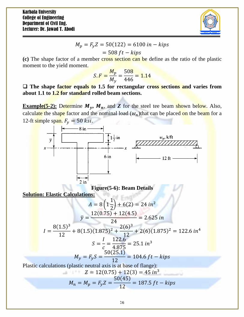
The shape factor equals to 1.5 for rectangular cross sections and varies from about 1.1 to 1.2 for standard rolled beam sections. Example(5-2): Determine 𝑴𝒚, 𝑴𝒏, and Z for the steel tee beam shown below. Also, calculate the shape factor and the nominal load (𝑤𝑛)that can be placed on the beam for a 12-ft simple span. 𝐹𝑦 = 50 𝑘𝑠𝑖.
Figure(5-6): Beam Details
Solution: Elastic Calculations:
𝐴 = 8 112 + 6(2) = 24 𝑖𝑛2
𝑦 =12(0.75) + 12(4.5)
24= 2.625 𝑖𝑛
𝐼 =8(1.5)3
12+ 8(1.5)(1.875)2 +
2(6)3
12+ 2(6)(1.875)2 = 122.6 𝑖𝑛4
𝑆 =𝐼𝑐
=122.64.875
= 25.1 𝑖𝑛3
𝑀𝑦 = 𝐹𝑦𝑆 =50(25.1)
12= 104.6 𝑓𝑡 − 𝑘𝑖𝑝𝑠
Plastic calculations (plastic neutral axis is at base of flange): 𝑍 = 12(0.75) + 12(3) = 45 𝑖𝑛3
𝑀𝑛 = 𝑀𝑝 = 𝐹𝑦𝑍 =50(45)
12= 187.5 𝑓𝑡 − 𝑘𝑖𝑝𝑠
76
Karbala University College of Engineering Department of Civil Eng. Lecturer: Dr. Jawad T. Abodi
𝑆ℎ𝑎𝑝𝑒 𝐹𝑎𝑐𝑡𝑜𝑟 =𝑀𝑝
𝑀𝑛 𝑜𝑟
𝑍𝑆
=45
25.1= 1.79
𝑀𝑛 =𝑤𝑛𝑙2
8 → 𝑤𝑛 =
8(187.5)12
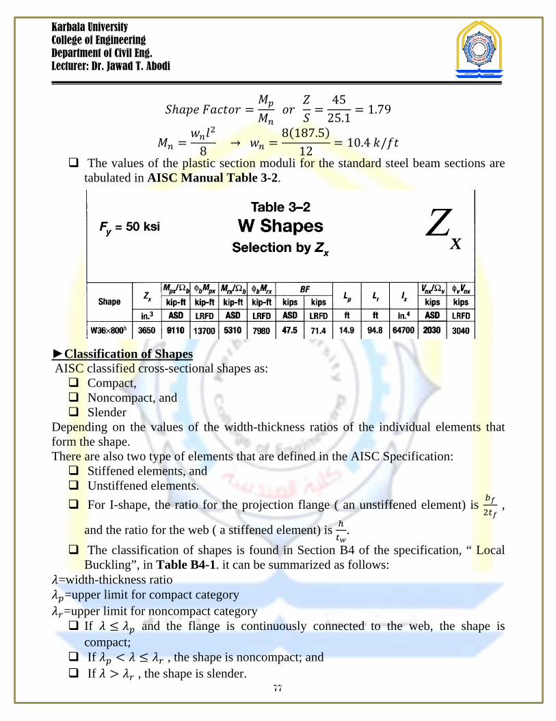
= 10.4 𝑘/𝑓𝑡 The values of the plastic section moduli for the standard steel beam sections are
tabulated in AISC Manual Table 3-2. Classification of Shapes AISC classified cross-sectional shapes as: Compact, Noncompact, and Slender
Depending on the values of the width-thickness ratios of the individual elements that form the shape. There are also two type of elements that are defined in the AISC Specification: Stiffened elements, and Unstiffened elements. For I-shape, the ratio for the projection flange ( an unstiffened element) is 𝑏𝑓
2𝑡𝑓 ,
and the ratio for the web ( a stiffened element) is ℎ𝑡𝑤
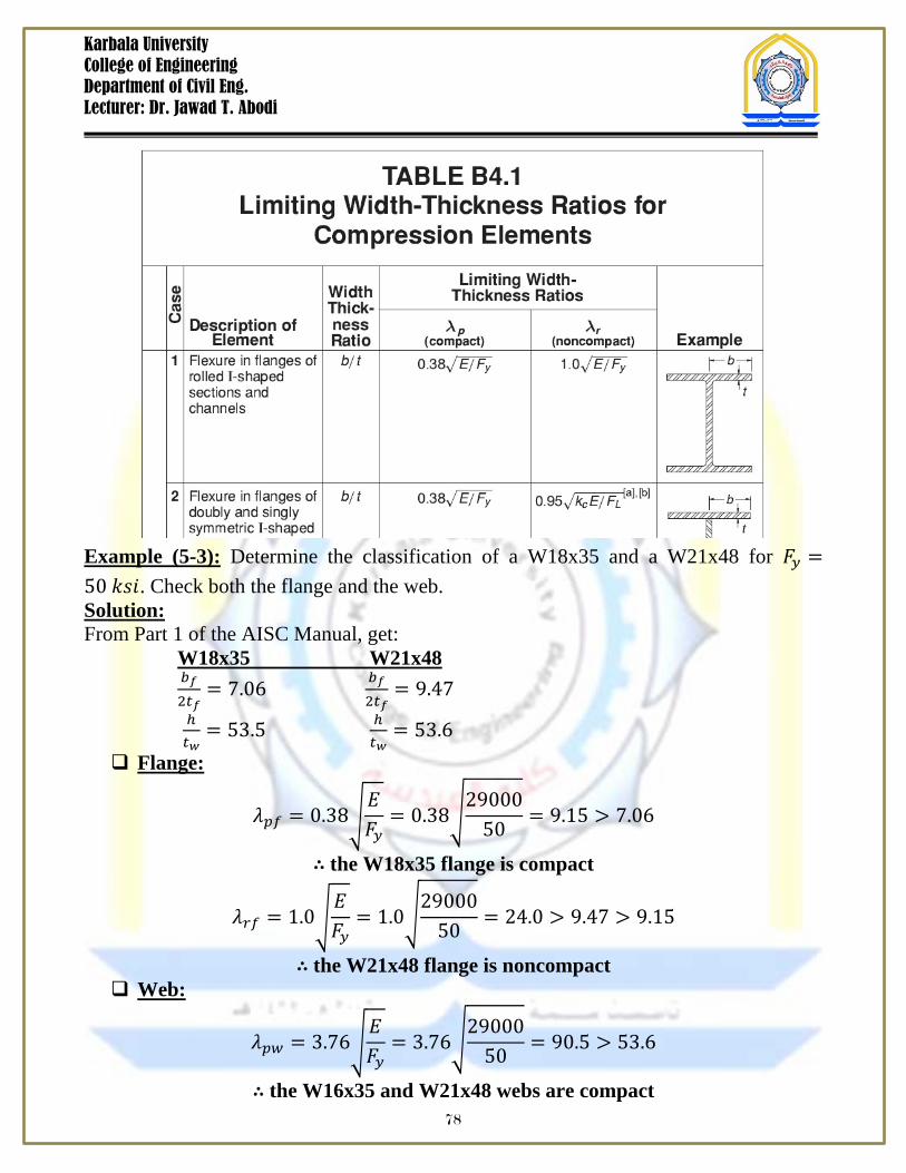
. The classification of shapes is found in Section B4 of the specification, “ Local
Buckling”, in Table B4-1. it can be summarized as follows: 𝜆=width-thickness ratio 𝜆𝑝=upper limit for compact category 𝜆𝑟=upper limit for noncompact category If 𝜆 ≤ 𝜆𝑝 and the flange is continuously connected to the web, the shape is
compact; If 𝜆𝑝 < 𝜆 ≤ 𝜆𝑟 , the shape is noncompact; and If 𝜆 > 𝜆𝑟 , the shape is slender.
77
Karbala University College of Engineering Department of Civil Eng. Lecturer: Dr. Jawad T. Abodi
Example (5-3): Determine the classification of a W18x35 and a W21x48 for 𝐹𝑦 =50 𝑘𝑠𝑖. Check both the flange and the web. Solution: From Part 1 of the AISC Manual, get: W18x35 W21x48 𝑏𝑓
2𝑡𝑓= 7.06 𝑏𝑓
2𝑡𝑓= 9.47
ℎ𝑡𝑤
= 53.5 ℎ𝑡𝑤
= 53.6 Flange:
𝜆𝑝𝑓 = 0.38𝐸𝐹𝑦
= 0.3829000
50= 9.15 > 7.06
∴ the W18x35 flange is compact
𝜆𝑟𝑓 = 1.0𝐸𝐹𝑦
= 1.029000
50= 24.0 > 9.47 > 9.15
∴ the W21x48 flange is noncompact Web:
𝜆𝑝𝑤 = 3.76𝐸𝐹𝑦
= 3.7629000
50= 90.5 > 53.6
∴ the W16x35 and W21x48 webs are compact 78
Karbala University College of Engineering Department of Civil Eng. Lecturer: Dr. Jawad T. Abodi
Bending Strength of Compact Shapes The basic design strength equation for beams in bending is: 𝑴𝒖 ≤ ∅𝒃𝑴𝒏 ( For LRFD) 𝑴𝒂 ≤
𝑴𝒏Ω𝒃
( For ASD) where 𝑀𝑢= Ultimate Moment, ∅𝑏 = 0.9 𝑀𝑎= Allowable Moment, Ω𝑏 = 1.67 𝑀𝑛= Nominal bending strength, ∅𝑏𝑀𝑛= Ultimate design bending strength, and 𝑀𝑛Ω𝑏
= Allowable design bending strength. The nominal bending strength, 𝑀𝑛, is a function of the following:
1) Lateral – torsional buckling ( LTB), 2) Flange local buckling (FLB), and 3) Web local buckling (WLB). Flange local buckling and web local buckling are localized failure modes and are
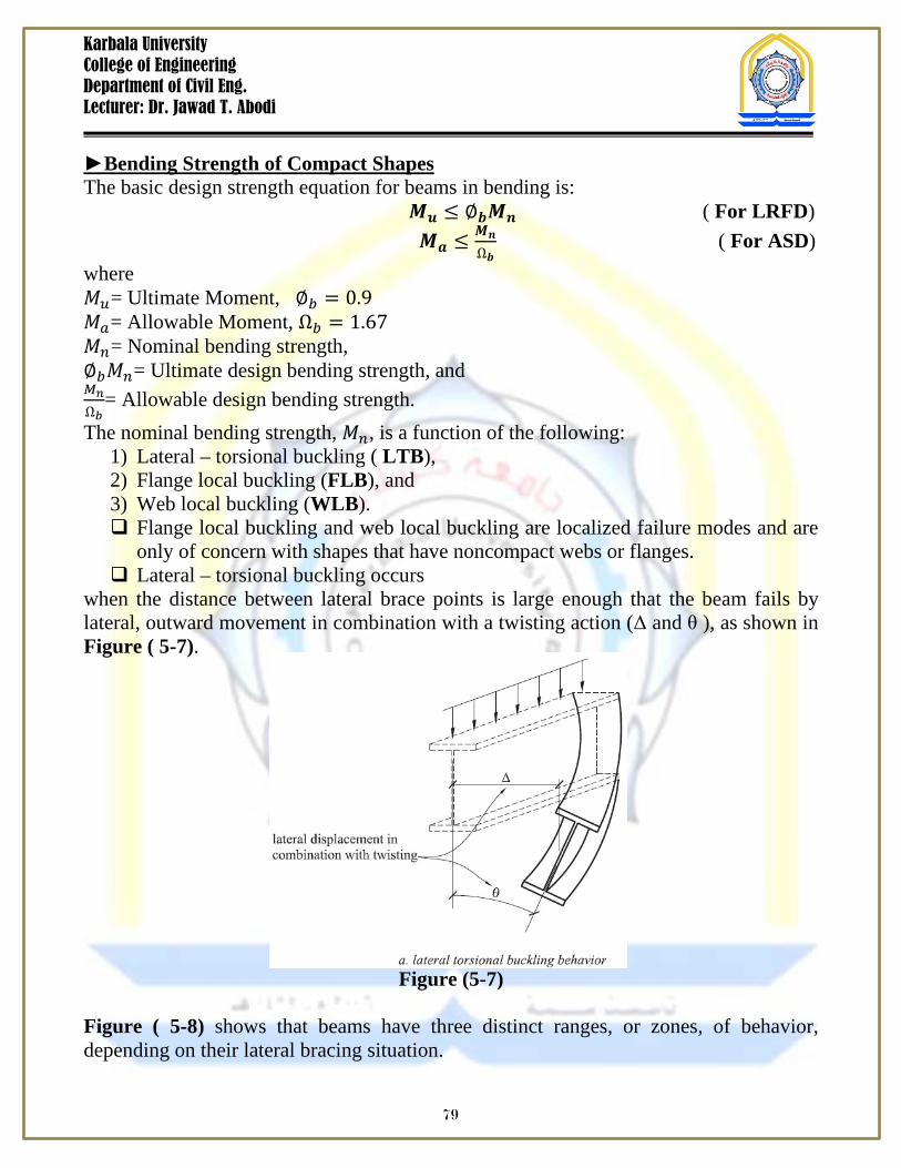
only of concern with shapes that have noncompact webs or flanges. Lateral – torsional buckling occurs
when the distance between lateral brace points is large enough that the beam fails by lateral, outward movement in combination with a twisting action (Δ and θ ), as shown in Figure ( 5-7).
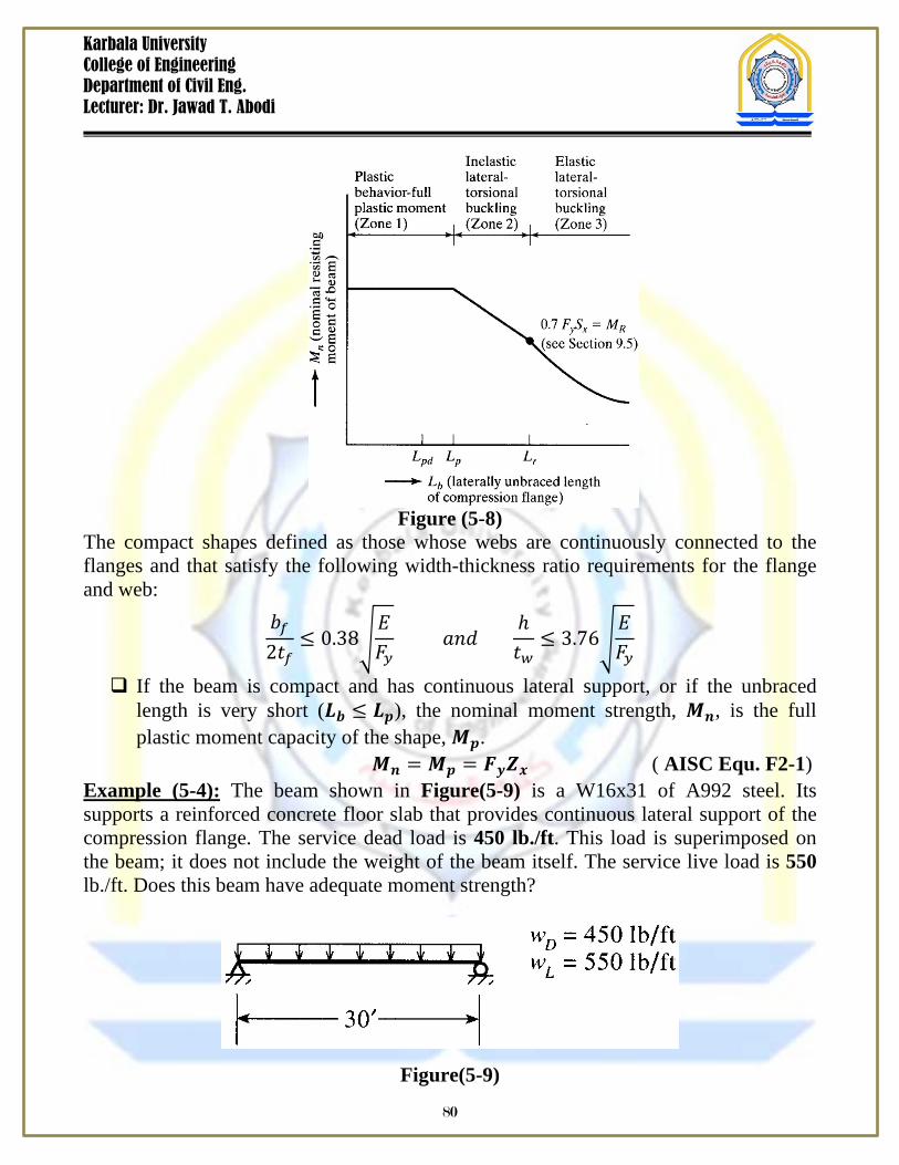
Figure (5-7) Figure ( 5-8) shows that beams have three distinct ranges, or zones, of behavior, depending on their lateral bracing situation.
79
Karbala University College of Engineering Department of Civil Eng. Lecturer: Dr. Jawad T. Abodi
Figure (5-8) The compact shapes defined as those whose webs are continuously connected to the flanges and that satisfy the following width-thickness ratio requirements for the flange and web:
𝑏𝑓2𝑡𝑓
≤ 0.38𝐸𝐹𝑦
𝑎𝑛𝑑 ℎ𝑡𝑤
≤ 3.76𝐸𝐹𝑦
If the beam is compact and has continuous lateral support, or if the unbraced length is very short (𝑳𝒃 ≤ 𝑳𝒑), the nominal moment strength, 𝑴𝒏, is the full plastic moment capacity of the shape, 𝑴𝒑.
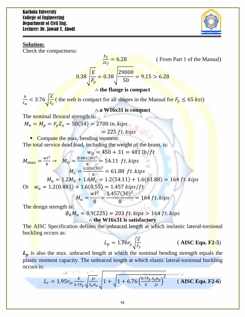
𝑴𝒏 = 𝑴𝒑 = 𝑭𝒚𝒁𝒙 ( AISC Equ. F2-1) Example (5-4): The beam shown in Figure(5-9) is a W16x31 of A992 steel. Its supports a reinforced concrete floor slab that provides continuous lateral support of the compression flange. The service dead load is 450 lb./ft. This load is superimposed on the beam; it does not include the weight of the beam itself. The service live load is 550 lb./ft. Does this beam have adequate moment strength?
Figure(5-9)
80
Karbala University College of Engineering Department of Civil Eng. Lecturer: Dr. Jawad T. Abodi
Solution: Check the compactness: 𝑏𝑓
2𝑡𝑓= 6.28 ( From Part 1 of the Manual)
0.38𝐸𝐹𝑦
= 0.3829000
50= 9.15 > 6.28
∴ the flange is compact ℎ𝑡𝑤
< 3.76𝐸𝐹𝑦
( the web is compact for all shapes in the Manual for 𝐹𝑦 ≤ 65 𝑘𝑠𝑖)
∴ a W16x31 is compact The nominal flexural strength is: 𝑀𝑛 = 𝑀𝑝 = 𝐹𝑦𝑍𝑥 = 50(54) = 2700 𝑖𝑛. 𝑘𝑖𝑝𝑠 = 225 𝑓𝑡. 𝑘𝑖𝑝𝑠 Compute the max. bending moment:
The total service dead load, including the weight of the beam, is: 𝑤𝐷 = 450 + 31 = 481 𝑙𝑏/𝑓𝑡 𝑀𝑚𝑎𝑥 = 𝑤𝑙2
8→ 𝑀𝐷 = 0.481(30)2
8= 54.11 𝑓𝑡. 𝑘𝑖𝑝𝑠
𝑀𝐿 = 0.550(30)2
8= 61.88 𝑓𝑡. 𝑘𝑖𝑝𝑠
𝑀𝑢 = 1.2𝑀𝐷 + 1.6𝑀𝐿 = 1.2(54.11) + 1.6(61.88) = 164 𝑓𝑡. 𝑘𝑖𝑝𝑠 Or 𝑤𝑢 = 1.2(0.481) + 1.6(0.55) = 1.457 𝑘𝑖𝑝𝑠/𝑓𝑡
𝑀𝑢 =𝑤𝑙2
8=
1.457(30)2
8= 164 𝑓𝑡. 𝑘𝑖𝑝𝑠
The design strength is: ∅𝑏𝑀𝑛 = 0.9(225) = 203 𝑓𝑡. 𝑘𝑖𝑝𝑠 > 164 𝑓𝑡. 𝑘𝑖𝑝𝑠
∴ the W16x31 is satisfactory The AISC Specification defines the unbraced length at which inelastic lateral-torsional buckling occurs as:
𝐿𝑝 = 1.76𝑟𝑦𝐸𝐹𝑦
( AISC Equ. F2-5)
𝑳𝒑 is also the max. unbraced length at which the nominal bending strength equals the plastic moment capacity. The unbraced length at which elastic lateral-torsional buckling occurs is:
𝐿𝑟 = 1.95𝑟𝑡𝑠𝐸
0.7𝐹𝑦 𝐽𝑐𝑆𝑥ℎ𝑜
1 + 1 + 6.76 0.7𝐹𝑦𝐸
𝑆𝑥ℎ𝑜𝐽𝑐2 ( AISC Equ. F2-6)
81
Karbala University College of Engineering Department of Civil Eng. Lecturer: Dr. Jawad T. Abodi
where, ( AISC Equ. F2-7) 𝑐 = 1.0 ( for I-shapes) ( AISC Equ. F2-8a)
𝑐 = ℎ𝑜2
𝐼𝑦𝐶𝑤
( for Channel shapes) ( AISC Equ. F2-8b)
𝐹𝑦 = Yield strength 𝐸 = Modulus of elasticity 𝐽 = Torsional constant 𝑆𝑥 = Section modulus ( x-axis) 𝐼𝑦 = Moment of inertia ( y-axis) 𝐶𝑤 = Warping constant, and ℎ𝑜 = Distance between flange centroids= 𝑑 − 𝑡𝑓. For compact I-shapes and C-shapes when 𝑳𝒑 < 𝑳𝒃 < 𝑳𝒓, the nominal flexural
strength is:
𝑀𝑛 = 𝐶𝑏 𝑀𝑝 − 𝑀𝑝 − 0.7𝐹𝑦𝑆𝑥 𝐿𝑏−𝐿𝑝𝐿𝑟−𝐿𝑝
≤ 𝑀𝑝 (AISC Equ. F2-2)
For compact I-shapes and C-shapes, when 𝑳𝒃 > 𝑳𝒓, the nominal flexural strength is:
𝑀𝑛 = 𝐹𝑐𝑟𝑆𝑥 ≤ 𝑀𝑝 ( AISC Equ. F2-3) where
𝐹𝑐𝑟 = 𝐶𝑏𝜋2𝐸
𝐿𝑏 𝑟𝑡𝑠 2 1 + 0.078 𝐽𝑐
𝑆𝑥ℎ𝑜𝐿𝑏𝑟𝑡𝑠2 ( AISC Equ. F2-4)
𝐶𝑏 =Moment gradient factor, factor to account for non-uniform bending within the unbraced length 𝐿𝑏. 𝐶𝑏 = 12.5𝑀𝑚𝑎𝑥
2.5𝑀𝑚𝑎𝑥+3𝑀𝐴+4𝑀𝐵+3𝑀𝐶𝑅𝑚 ≤ 3.0 ( AISC Equ. F1-1)
where 𝑀𝑚𝑎𝑥 =Absolute value of the maximum moment in the unbraced segment, 𝑀𝐴 =Absolute value of the moment at the ¼ point of the unbraced segment, 𝑀𝐵 =Absolute value of the moment at the centerline of the unbraced segment, 𝑀𝐶 =Absolute value of the moment at the 3/4 point of the unbraced segment, 𝑅𝑚 =Section symmetry factor 𝑅𝑚 = 1.0 , for doubly symmetric members ( I-shapes), 𝑅𝑚 = 1.0 , for singly symmetric sections in single-curvature bending,
𝑅𝑚 = 0.5 + 2 𝐼𝑦𝑐𝐼𝑦2 , for single symmetric shapes subjected to reverse curvature
bending, and 𝐼𝑦𝑐 =Moment of inertia of the compression flange about the y-axis. 𝐶𝑏 = 1.0 , for cantilevers or overhangs where the free end is unbraced.
82
Karbala University College of Engineering Department of Civil Eng. Lecturer: Dr. Jawad T. Abodi
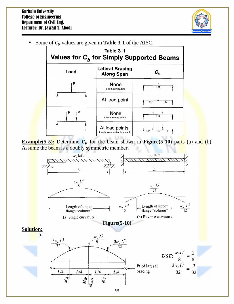
Some of 𝐶𝑏 values are given in Table 3-1 of the AISC.
Example(5-5): Determine 𝑪𝒃 for the beam shown in Figure(5-10) parts (a) and (b). Assume the beam is a doubly symmetric member.
Figure(5-10) Solution:
83
Karbala University College of Engineering Department of Civil Eng. Lecturer: Dr. Jawad T. Abodi
𝐶𝑏 =12.5𝑀𝑚𝑎𝑥
2.5𝑀𝑚𝑎𝑥 + 3𝑀𝐴 + 4𝑀𝐵 + 3𝑀𝐶𝑅𝑚 ≤ 3.0
𝐶𝑏 =12.5 1
8
2.5 18 + 3 3
32 + 4 18 + 3 3
32= 1.14
𝐶𝑏 =12.5 1
12
2.5 112 + 3 3
96 + 4 124 + 3 3
96= 2.38
Example (5-6): Determine the flexural strength of a W14x68 of A242 steel, Grade 50, subjected to:
a) Continuous lateral support. b) An unbraced length of 20 ft with 𝐶𝑏 = 1.0 c) An unbraced length of 30 ft with 𝐶𝑏 = 1.0
Solution: Determine whether this shape is compact, noncompact, or slender:
𝑏𝑓2𝑡𝑓
= 6.97 ( from Part 1 of the Manual)
0.38𝐸𝐹𝑦
= 0.3829000
50= 9.15 > 6.97
∴ the flange is compact The web is compact for all shapes in the Manual for 𝐹𝑦 ≤ 65 𝑘𝑠𝑖
a) Because the beam is compact and laterally supported (𝐿𝑏 = 0 < 𝐿𝑝), the nominal flexural strength is:
𝑀𝑛 = 𝑀𝑝 = 𝐹𝑦𝑍𝑥 = 50(115) = 5750 𝑖𝑛. 𝑘𝑖𝑝𝑠 = 479.2 𝑓𝑡. 𝑘𝑖𝑝𝑠
84
Karbala University College of Engineering Department of Civil Eng. Lecturer: Dr. Jawad T. Abodi
LRFD Solution: The design strength is:
∅𝑏𝑀𝑛 = 0.9(479.2) = 431 𝑓𝑡. 𝑘𝑖𝑝𝑠 ASD Solution: The allowable moment strength is:
𝑀𝑛
Ω𝑏=
479.21.67
= 288 𝑓𝑡.𝑘𝑖𝑝𝑠
b) 𝐿𝑏 = 20 𝑓𝑡 𝑎𝑛𝑑 𝐶𝑏 = 1.0. First, determine 𝐿𝑝 and 𝐿𝑟:
𝐿𝑝 = 1.76𝑟𝑦𝐸𝐹𝑦
= 1.76(2.46)29000
50= 104.3 𝑖𝑛 = 8.692 𝑓𝑡
The following terms will be needed in the computation of 𝐿𝑟:
= 𝐼𝑦𝐶𝑤𝑆𝑥
= 121(5380)103
= 7.833 𝑖𝑛2
𝑟𝑡𝑠 = √7.833 = 2.799 𝑖𝑛 (𝑟𝑡𝑠 can also be found in the dimensions and properties tables in Part 1 of the Manual).
ℎ𝑜 = 𝑑 − 𝑡𝑓 = 14.0 − 0.72 = 13.28 𝑖𝑛 (ℎ𝑜 can also be found in the dimensions and properties tables in Part 1 of the Manual). For a doubly-symmetric I-shape, 𝑐 = 1.0 ( From AISC Equ. F2-6).
𝐿𝑟 = 1.95𝑟𝑡𝑠𝐸
0.7𝐹𝑦
𝐽𝑐𝑆𝑥ℎ𝑜
1 + 1 + 6.76 0.7𝐹𝑦𝐸
𝑆𝑥ℎ𝑜𝐽𝑐
2
𝐿𝑟 = 1.95(2.799)29000
0.7(50)
3.01(1.0)103(13.28)
1 + 1 + 6.760.7(50)29000
103(13.28)3.01(1.0)
2
𝐿𝑟 = 351.3 𝑖𝑛 = 29.28 𝑓𝑡 Since 𝐿𝑝 < 𝐿𝑏 < 𝐿𝑟, then:
𝑀𝑛 = 𝐶𝑏 𝑀𝑝 − 𝑀𝑝 − 0.7𝐹𝑦𝑆𝑥 𝐿𝑏 − 𝐿𝑝𝐿𝑟 − 𝐿𝑝
≤ 𝑀𝑝
= 1.0 5750 − (5750 − 0.7 × 50 × 103) 20 − 8.692
29.28 − 8.692
𝑀𝑛 = 4572 𝑖𝑛. 𝑘𝑖𝑝𝑠 = 381 𝑓𝑡. 𝑘 < 𝑀𝑝 = 479.2 𝑓𝑡. 𝑘 LRFD Solution: The design strength is:
∅𝑏𝑀𝑛 = 0.9(381) = 343 𝑓𝑡. 𝑘𝑖𝑝𝑠 ASD Solution: The allowable moment strength is:
𝑀𝑛
Ω𝑏=
3811.67
= 229 𝑓𝑡. 𝑘𝑖𝑝𝑠
85
Karbala University College of Engineering Department of Civil Eng. Lecturer: Dr. Jawad T. Abodi
c) 𝑳𝒃 = 𝟑𝟎 𝒇𝒕 𝒂𝒏𝒅 𝑪𝒃 = 𝟏.𝟎 Since 𝐿𝑏 > 𝐿𝑟 = 29.28, then: 𝑀𝑛 = 𝐹𝑐𝑟𝑆𝑥 ≤ 𝑀𝑝 ( AISC Equ. F2-3)
𝐹𝑐𝑟 =𝐶𝑏𝜋2𝐸
𝐿𝑏 𝑟𝑡𝑠 2 1 + 0.078
𝐽𝑐𝑆𝑥ℎ𝑜
𝐿𝑏𝑟𝑡𝑠2
𝐹𝑐𝑟 =𝜋2(29000)
30 × 122.799
2 1 + 0.0783.01(1)
103(13.28) 30 × 12
2.7992
𝐹𝑐𝑟 = 33.9 𝑘𝑠𝑖 and
𝑀𝑛 = 33.9(103) = 3492 𝑖𝑛. 𝑘 = 291 𝑓𝑡.𝑘 < 𝑀𝑝 = 479.2 𝑓𝑡. 𝑘 LRFD Solution: ∅𝑏𝑀𝑛 = 0.9(291) = 262 𝑓𝑡. 𝑘𝑖𝑝𝑠 ASD Solution: 𝑀𝑛
Ω𝑏= 291
1.67= 175 𝑓𝑡. 𝑘𝑖𝑝𝑠
Non-Compact Shapes
The noncompact sections are those that have web-thickness ratios greater than 𝝀𝒑 , but not greater than 𝝀𝒓. For the noncompact range, the width-thickness ratios of the flanges of W or other I-shaped rolled sections must not exceed 𝜆𝑟 = 1.0𝐸 𝐹𝑦⁄ , while those for the webs must not exceed 𝜆𝑟 = 5.7𝐸 𝐹𝑦⁄ . Other values are provided in AISC Table B4.1b for 𝝀𝒑 and 𝝀𝒓 for other shapes From AISC F3, Flange local buckling, if 𝜆𝑝 < 𝜆 ≤ 𝜆𝑟, the flange is noncompact, buckling will be inelastic, and
𝑀𝑛 = 𝑀𝑝 − 𝑀𝑝 − 0.7𝐹𝑦𝑆𝑥 𝜆−𝜆𝑝𝜆𝑟−𝜆𝑝
( AISC Equ. F3-1)
where 𝜆 = 𝑏𝑓2𝑡𝑓
, 𝜆𝑝 = 0.38𝐸𝐹𝑦
, 𝑎𝑛𝑑 𝜆𝑟 = 1.0𝐸𝐹𝑦
Example(5-7): A simply supported beam with a span length of 45 ft is laterally supported at its ends and is subjected to the following service loads: Dead load=400 lb./ft ( including beam weight). Live load=1000 lb./ft. If 𝐹𝑦 = 50 𝑘𝑠𝑖, is a W14x90 adequate?
86
Karbala University College of Engineering Department of Civil Eng. Lecturer: Dr. Jawad T. Abodi
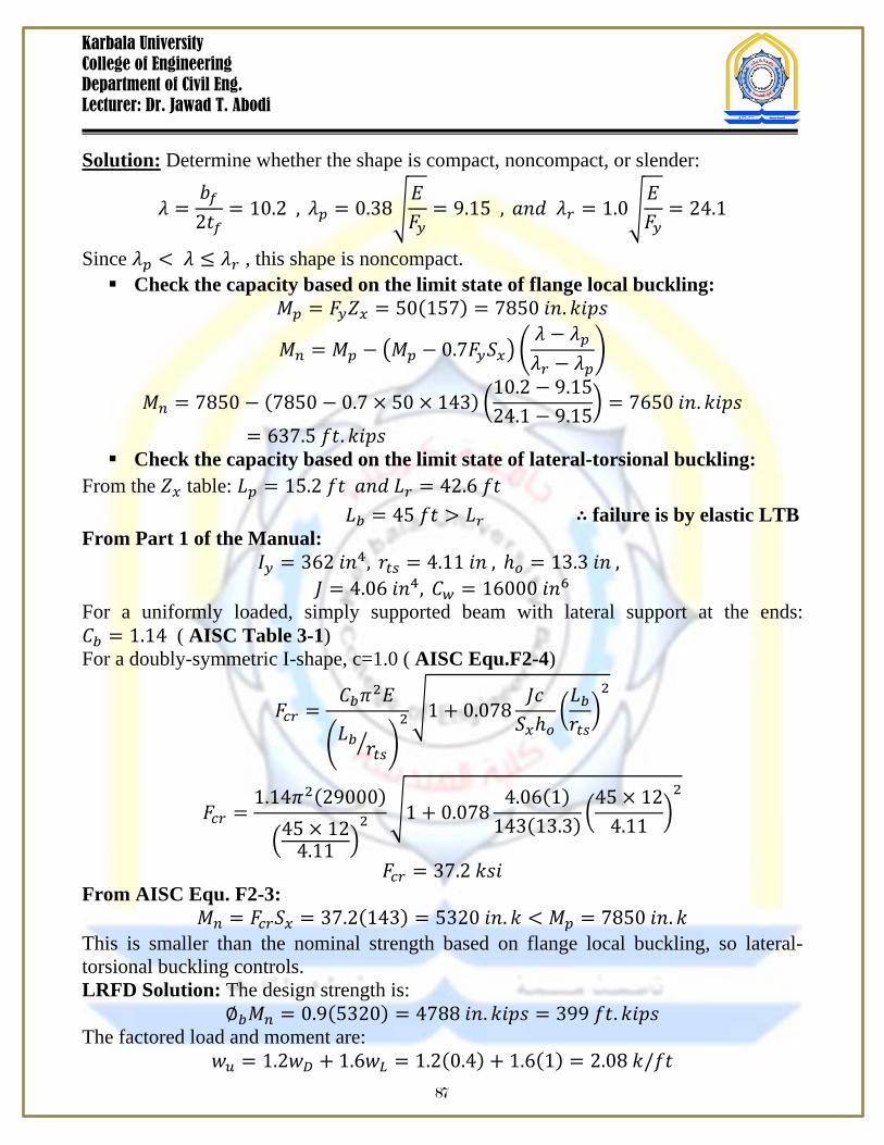
Solution: Determine whether the shape is compact, noncompact, or slender:
𝜆 =𝑏𝑓2𝑡𝑓
= 10.2 , 𝜆𝑝 = 0.38𝐸𝐹𝑦
= 9.15 , 𝑎𝑛𝑑 𝜆𝑟 = 1.0𝐸𝐹𝑦
= 24.1
Since 𝜆𝑝 < 𝜆 ≤ 𝜆𝑟 , this shape is noncompact. Check the capacity based on the limit state of flange local buckling:
𝑀𝑝 = 𝐹𝑦𝑍𝑥 = 50(157) = 7850 𝑖𝑛.𝑘𝑖𝑝𝑠
𝑀𝑛 = 𝑀𝑝 − 𝑀𝑝 − 0.7𝐹𝑦𝑆𝑥 𝜆 − 𝜆𝑝𝜆𝑟 − 𝜆𝑝
𝑀𝑛 = 7850 − (7850 − 0.7 × 50 × 143) 10.2 − 9.1524.1 − 9.15
= 7650 𝑖𝑛. 𝑘𝑖𝑝𝑠= 637.5 𝑓𝑡. 𝑘𝑖𝑝𝑠
Check the capacity based on the limit state of lateral-torsional buckling: From the 𝑍𝑥 table: 𝐿𝑝 = 15.2 𝑓𝑡 𝑎𝑛𝑑 𝐿𝑟 = 42.6 𝑓𝑡 𝐿𝑏 = 45 𝑓𝑡 > 𝐿𝑟 ∴ failure is by elastic LTB From Part 1 of the Manual:
𝐼𝑦 = 362 𝑖𝑛4, 𝑟𝑡𝑠 = 4.11 𝑖𝑛 , ℎ𝑜 = 13.3 𝑖𝑛 , 𝐽 = 4.06 𝑖𝑛4, 𝐶𝑤 = 16000 𝑖𝑛6
For a uniformly loaded, simply supported beam with lateral support at the ends: 𝐶𝑏 = 1.14 ( AISC Table 3-1) For a doubly-symmetric I-shape, c=1.0 ( AISC Equ.F2-4)
𝐹𝑐𝑟 =𝐶𝑏𝜋2𝐸
𝐿𝑏 𝑟𝑡𝑠 2 1 + 0.078
𝐽𝑐𝑆𝑥ℎ𝑜
𝐿𝑏𝑟𝑡𝑠2
𝐹𝑐𝑟 =1.14𝜋2(29000)
45 × 124.11
21 + 0.078
4.06(1)143(13.3)
45 × 124.11
2
𝐹𝑐𝑟 = 37.2 𝑘𝑠𝑖 From AISC Equ. F2-3:
𝑀𝑛 = 𝐹𝑐𝑟𝑆𝑥 = 37.2(143) = 5320 𝑖𝑛. 𝑘 < 𝑀𝑝 = 7850 𝑖𝑛. 𝑘 This is smaller than the nominal strength based on flange local buckling, so lateral-torsional buckling controls. LRFD Solution: The design strength is:
∅𝑏𝑀𝑛 = 0.9(5320) = 4788 𝑖𝑛. 𝑘𝑖𝑝𝑠 = 399 𝑓𝑡. 𝑘𝑖𝑝𝑠 The factored load and moment are:
𝑤𝑢 = 1.2𝑤𝐷 + 1.6𝑤𝐿 = 1.2(0.4) + 1.6(1) = 2.08 𝑘/𝑓𝑡 87
Karbala University College of Engineering Department of Civil Eng. Lecturer: Dr. Jawad T. Abodi
𝑀𝑢 =𝑤𝑢𝐿2
8=
2.08(45)2
8= 527 𝑓𝑡. 𝑘 > 399𝑓𝑡. 𝑘 𝑁.𝐺
Summary of Moment Strength This summary is for compact and noncompact shapes (noncompact flanges) only ( no slender shapes):
1) Determine whether the shape is compact. 2) If the shape is compact, check for lateral-torsional buckling as follows:
Using 𝐿𝑝 = 1.76𝑟𝑦𝐸𝐹𝑦
,
If 𝐿𝑏 ≤ 𝐿𝑝, there is no LTB, and 𝑀𝑛 = 𝑀𝑝 If 𝐿𝑝 < 𝐿𝑏 ≤ 𝐿𝑟, there is inelastic LTB, and
𝑀𝑛 = 𝐶𝑏 𝑀𝑝 − 𝑀𝑝 − 0.7𝐹𝑦𝑆𝑥 𝐿𝑏 − 𝐿𝑝𝐿𝑟 − 𝐿𝑝
≤ 𝑀𝑝
If 𝐿𝑏 > 𝐿𝑟, there is inelastic LTB, and 𝑀𝑛 = 𝐹𝑐𝑟𝑆𝑥 ≤ 𝑀𝑝
Where 𝐹𝑐𝑟 = 𝐶𝑏𝜋2𝐸
𝐿𝑏 𝑟𝑡𝑠 2 1 + 0.078 𝐽𝑐
𝑆𝑥ℎ𝑜𝐿𝑏𝑟𝑡𝑠2
3) If the shape is noncompact because of the flange, the nominal strength will be the smaller of the strength corresponding to flange local buckling and lateral-torsional buckling.
a) Flange local buckling: If 𝜆 ≤ 𝜆𝑝, there is no FTB, If 𝜆𝑝 < 𝜆 ≤ 𝜆𝑟, the flange is noncompact, and
𝑀𝑛 = 𝑀𝑝 − 𝑀𝑝 − 0.7𝐹𝑦𝑆𝑥 𝜆 − 𝜆𝑝𝜆𝑟 − 𝜆𝑝
b) Lateral-torsional buckling:
Using 𝐿𝑝 = 1.76𝑟𝑦𝐸𝐹𝑦
,
If 𝐿𝑏 ≤ 𝐿𝑝, there is no LTB, If 𝐿𝑝 < 𝐿𝑏 ≤ 𝐿𝑟, there is inelastic LTB, and
𝑀𝑛 = 𝐶𝑏 𝑀𝑝 − 𝑀𝑝 − 0.7𝐹𝑦𝑆𝑥 𝐿𝑏 − 𝐿𝑝𝐿𝑟 − 𝐿𝑝
≤ 𝑀𝑝
If 𝐿𝑏 > 𝐿𝑟, there is elastic LTB, and 𝑀𝑛 = 𝐹𝑐𝑟𝑆𝑥 ≤ 𝑀𝑝
88
Karbala University College of Engineering Department of Civil Eng. Lecturer: Dr. Jawad T. Abodi
Where 𝐹𝑐𝑟 = 𝐶𝑏𝜋2𝐸
𝐿𝑏 𝑟𝑡𝑠 2 1 + 0.078 𝐽𝑐
𝑆𝑥ℎ𝑜𝐿𝑏𝑟𝑡𝑠2
Design for Shear Generally, shear is not a problem in steel beams, because the webs of rolled shapes
are capable of resisting rather large shearing forces. Perhaps it is well, however, to list the most common situation where shear might be excessive:
1) Should large concentrated loads be placed near beam supports. 2) Probably the most common shear problem occurs where two members ( as a beam
and column) are rigidly connected together so that their webs lie in a common plane.
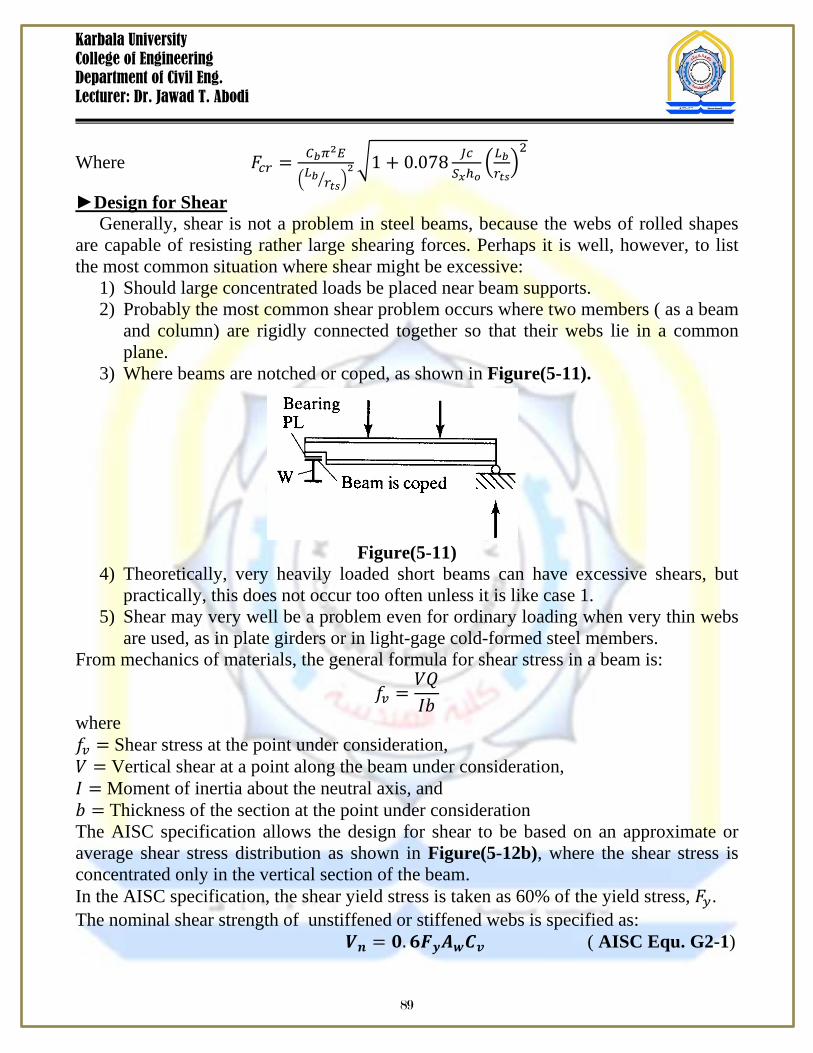
3) Where beams are notched or coped, as shown in Figure(5-11).
Figure(5-11) 4) Theoretically, very heavily loaded short beams can have excessive shears, but
practically, this does not occur too often unless it is like case 1. 5) Shear may very well be a problem even for ordinary loading when very thin webs
are used, as in plate girders or in light-gage cold-formed steel members. From mechanics of materials, the general formula for shear stress in a beam is:
𝑓𝑣 =𝑉𝑄𝐼𝑏
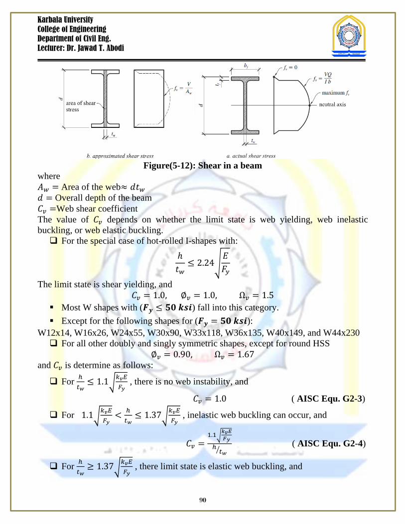
where 𝑓𝑣 = Shear stress at the point under consideration, 𝑉 = Vertical shear at a point along the beam under consideration, 𝐼 = Moment of inertia about the neutral axis, and 𝑏 = Thickness of the section at the point under consideration The AISC specification allows the design for shear to be based on an approximate or average shear stress distribution as shown in Figure(5-12b), where the shear stress is concentrated only in the vertical section of the beam. In the AISC specification, the shear yield stress is taken as 60% of the yield stress, 𝐹𝑦. The nominal shear strength of unstiffened or stiffened webs is specified as: 𝑽𝒏 = 𝟎.𝟔𝑭𝒚𝑨𝒘𝑪𝒗 ( AISC Equ. G2-1)
89
Karbala University College of Engineering Department of Civil Eng. Lecturer: Dr. Jawad T. Abodi
Figure(5-12): Shear in a beam where 𝐴𝑤 = Area of the web≈ 𝑑𝑡𝑤 𝑑 = Overall depth of the beam 𝐶𝑣 =Web shear coefficient The value of 𝐶𝑣 depends on whether the limit state is web yielding, web inelastic buckling, or web elastic buckling. For the special case of hot-rolled I-shapes with:
ℎ𝑡𝑤
≤ 2.24𝐸𝐹𝑦
The limit state is shear yielding, and 𝐶𝑣 = 1.0, ∅𝑣 = 1.0, Ω𝑣 = 1.5
Most W shapes with (𝑭𝒚 ≤ 𝟓𝟎 𝒌𝒔𝒊) fall into this category. Except for the following shapes for (𝑭𝒚 = 𝟓𝟎 𝒌𝒔𝒊):
W12x14, W16x26, W24x55, W30x90, W33x118, W36x135, W40x149, and W44x230 For all other doubly and singly symmetric shapes, except for round HSS
∅𝑣 = 0.90, Ω𝑣 = 1.67 and 𝐶𝑣 is determine as follows:
For ℎ𝑡𝑤≤ 1.1
𝑘𝑣𝐸𝐹𝑦
, there is no web instability, and
𝐶𝑣 = 1.0 ( AISC Equ. G2-3)
For 1.1𝑘𝑣𝐸𝐹𝑦
< ℎ𝑡𝑤≤ 1.37
𝑘𝑣𝐸𝐹𝑦
, inelastic web buckling can occur, and
𝐶𝑣 =1.1
𝑘𝑣𝐸𝐹𝑦
ℎ𝑡𝑤
( AISC Equ. G2-4)
For ℎ𝑡𝑤≥ 1.37
𝑘𝑣𝐸𝐹𝑦
, there limit state is elastic web buckling, and
90
Karbala University College of Engineering Department of Civil Eng. Lecturer: Dr. Jawad T. Abodi
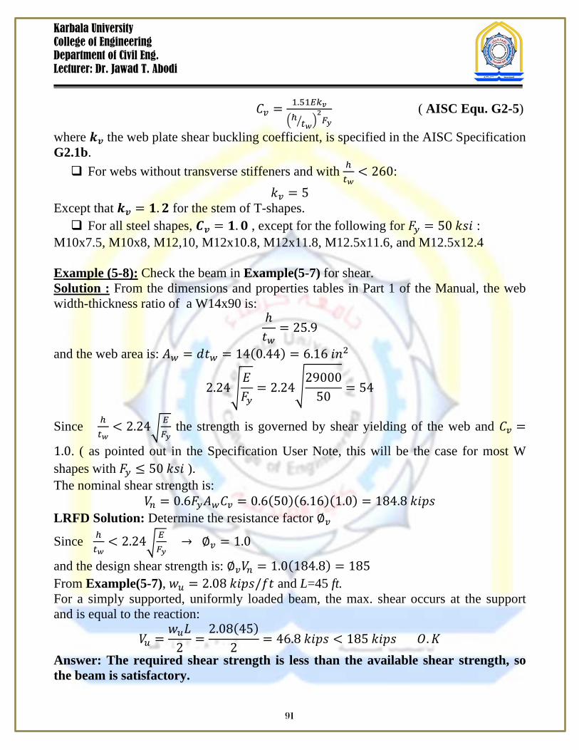
𝐶𝑣 = 1.51𝐸𝑘𝑣
ℎ 𝑡𝑤 2𝐹𝑦
( AISC Equ. G2-5)
where 𝒌𝒗 the web plate shear buckling coefficient, is specified in the AISC Specification G2.1b. For webs without transverse stiffeners and with ℎ
𝑡𝑤< 260:
𝑘𝑣 = 5 Except that 𝒌𝒗 = 𝟏.𝟐 for the stem of T-shapes. For all steel shapes, 𝑪𝒗 = 𝟏.𝟎 , except for the following for 𝐹𝑦 = 50 𝑘𝑠𝑖 :
M10x7.5, M10x8, M12,10, M12x10.8, M12x11.8, M12.5x11.6, and M12.5x12.4 Example (5-8): Check the beam in Example(5-7) for shear. Solution : From the dimensions and properties tables in Part 1 of the Manual, the web width-thickness ratio of a W14x90 is:
ℎ𝑡𝑤
= 25.9
and the web area is: 𝐴𝑤 = 𝑑𝑡𝑤 = 14(0.44) = 6.16 𝑖𝑛2
2.24𝐸𝐹𝑦
= 2.2429000
50= 54
Since ℎ𝑡𝑤
< 2.24𝐸𝐹𝑦
the strength is governed by shear yielding of the web and 𝐶𝑣 =
1.0. ( as pointed out in the Specification User Note, this will be the case for most W shapes with 𝐹𝑦 ≤ 50 𝑘𝑠𝑖 ). The nominal shear strength is:
𝑉𝑛 = 0.6𝐹𝑦𝐴𝑤𝐶𝑣 = 0.6(50)(6.16)(1.0) = 184.8 𝑘𝑖𝑝𝑠 LRFD Solution: Determine the resistance factor ∅𝑣
Since ℎ𝑡𝑤
< 2.24𝐸𝐹𝑦
→ ∅𝑣 = 1.0
and the design shear strength is: ∅𝑣𝑉𝑛 = 1.0(184.8) = 185 From Example(5-7), 𝑤𝑢 = 2.08 𝑘𝑖𝑝𝑠/𝑓𝑡 and L=45 ft. For a simply supported, uniformly loaded beam, the max. shear occurs at the support and is equal to the reaction:
𝑉𝑢 =𝑤𝑢𝐿
2=
2.08(45)2
= 46.8 𝑘𝑖𝑝𝑠 < 185 𝑘𝑖𝑝𝑠 𝑂.𝐾 Answer: The required shear strength is less than the available shear strength, so the beam is satisfactory.
91
Karbala University College of Engineering Department of Civil Eng. Lecturer: Dr. Jawad T. Abodi
The values of ∅𝑣𝑉𝑛𝑥 𝑎𝑛𝑑 𝑉𝑛𝑥 Ω𝑣 with 𝐹𝑦 = 50 𝑘𝑠𝑖 are given for W shapes in the
Manual Table 3-2. A very useful Table(3-6) is provided in Part 3 of the AISC Manual for
determining the max. uniform load each W shape can support for various spans. Beam Design Tables The design bending strength of W-shapes and C-shapes with respect to the
unbraced length is given in AISC, Tables 3-10 and 3-11, respectively. These tables assume a moment gradient factor of Cb=1.0, which is conservative for all cases, and yield strengths of Fy=50 ksi for W-shapes and Fy=36 ksi for C-shapes.
For beams with Cb greater than 1.0, multiply the moment capacity calculated using these tables by the Cb value to obtain the actual design moment capacity of the beam for design moments that correspond to unbraced lengths greater than Lp. Note that 𝐶𝑏∅𝑀𝑛must always be less than ∅𝑀𝑝 .
AISC, Tables 3-2 through 3-5 can be used to select the most economical beam based on section properties. AISC, Table 3-2 lists the plastic section modulus, Zx, for a given series of shapes, with the most economical in one series at the top of the list in bold font.
AISC, Table 3-6 provides a useful summary of the beam design parameters for W-shapes. The lower part of the table provides values for ØMp, ØMr, ØVn, Lp, and Lr for any given shape. The upper portion of the table provides the maximum possible load that a beam may support based on either shear or bending strength.
AISC, Table 3-6 can also be used to determine the design bending strength for a given beam if the unbraced length is between Lp and Lr. When the unbraced length is within this range, the design bending strength is:
∅𝑏𝑀𝑛 = ∅𝑏𝑀𝑝 − 𝐵𝐹𝐿𝑏 − 𝐿𝑝 where BF is a constant found from AISC Table 3-6. Note that this equation is simpler version of (AISC Equ. F2-2) Deflection The deflections of steel beams are usually limited to certain maximum values. Among the several excellent reasons for deflection limitations are the following:
1) Excessive deflections may damage other materials attached to or supported by the beam in equation.
2) The appearance of structures is often damaged by excessive deflections. 3) Extreme deflections do not inspire confidence in the persons using a structure. 4) It may be necessary for several different beams supporting the same loads to
deflect equal amounts.
92
Karbala University College of Engineering Department of Civil Eng. Lecturer: Dr. Jawad T. Abodi
The student should note that deflection limitations fall in the serviceability area.
Therefore, deflections are determined for service loads, and thus the calculations are identical for both LRFD and ASD designs.
For the common case of a simply supported, uniformly loaded beam, the max. vertical deflection is:
∆=5
384𝑤𝐿4
𝐸𝐼
Deflection formulas for a variety of beams and loading conditions can be found in Part 3 of the Manual.
Beam Design Procedure The design process can be outlined as follows:-
1) Determine the service and factored loads on the beam. Service loads are used for deflection calculations and factored loads are used for strength design. The weight of the beam would be unknown at this stage, but the self-weight can be initially estimated and is usually comparatively small enough not to affect the design.
2) Determine the factored shear and moments on the beam. 3) Select a shape that satisfies strength and deflection criteria. One of the following
methods can be used: a) For shapes listed in the AISC beam design tables, select the most economical
beam to support the factored moment. Then check deflection and shear for the selected shape.
b) Determine the required moment of inertia. Select the most economical shape based on the moment of inertia calculated, and check this shape for bending and shear.
c) For shapes not listed in the AISC beam design tables, an initial size must be assumed. An estimate of the available bending strength can be made for an initial beam selection; then check shear and deflection. A more accurate method might be to follow the procedure in step b above.
4) Check the shear strength. 5) Check the deflection.
Example(5-9): For the floor plan shown in Figure (5-13), design members B1 and G1 for bending, shear, and deflection. Compare deflections with L/240 for total loads and L/360 for live loads. The steel is ASTM A992, grade 50; assume that 𝐶𝑏 = 1.0 for bending. The dead load ( including the beam weight) is assumed to be (85 psf) and the live load is (150 psf). Assume that the floor deck provides full lateral stability to the top flange of B1 Ignore live load reduction. Use the design tables in the AISC where appropriate.
93
Karbala University College of Engineering Department of Civil Eng. Lecturer: Dr. Jawad T. Abodi
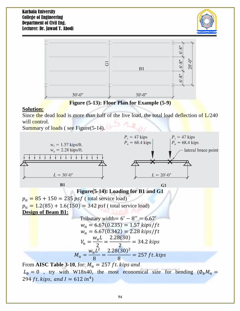
Figure (5-13): Floor Plan for Example (5-9)
Solution: Since the dead load is more than half of the live load, the total load deflection of L/240 will control. Summary of loads ( see Figure(5-14).
Figure(5-14): Loading for B1 and G1 𝑝𝑎 = 85 + 150 = 235 𝑝𝑠𝑓 ( total service load) 𝑝𝑢 = 1.2(85) + 1.6(150) = 342 𝑝𝑠f ( total service load) Design of Beam B1: Tributary width= 6′ − 8′′ = 6.67′
𝑤𝑎 = 6.67(0.235) = 1.57 𝑘𝑖𝑝𝑠/𝑓𝑡 𝑤𝑢 = 6.67(0.342) = 2.28 𝑘𝑖𝑝𝑠/𝑓𝑡
𝑉𝑢 =𝑤𝑢𝐿
2=
2.28(30)2
= 34.2 𝑘𝑖𝑝𝑠
𝑀𝑢 =𝑤𝑢𝐿2
8=
2.28(30)2
8= 257 𝑓𝑡.𝑘𝑖𝑝𝑠
From AISC Table 3-10, for: 𝑀𝑢 = 257 𝑓𝑡. 𝑘𝑖𝑝𝑠 𝑎𝑛𝑑 𝐿𝑏 = 0 , try with W18x40, the most economical size for bending (∅𝑏𝑀𝑛 =294 𝑓𝑡. 𝑘𝑖𝑝𝑠, 𝑎𝑛𝑑 𝐼 = 612 𝑖𝑛4)
94
Karbala University College of Engineering Department of Civil Eng. Lecturer: Dr. Jawad T. Abodi
𝑀 =𝑤𝐿2
8→ 8𝑀 = 𝑤𝐿2
∆=5𝑤𝐿4
384𝐸𝐼=
5(8𝑀)𝐿2
384𝐸𝐼=
40𝑀𝐿2(1728)384(29000)𝐼
=𝑀𝐿2
161.1𝐼
𝐿(12)240
=𝑀𝐿2
161.1𝐼
𝐼𝑟𝑒𝑞. =𝑀𝐿2
8.056=
𝑤𝐿2
64.44=
1.57(30)2
64.44= 658 𝑖𝑛4
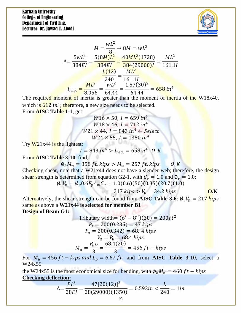
The required moment of inertia is greater than the moment of inertia of the W18x40, which is 612 𝑖𝑛4; therefore, a new size needs to be selected. From AISC Table 1-1, get:
𝑊16 × 50, 𝐼 = 659 𝑖𝑛4 𝑊18 × 46, 𝐼 = 712 𝑖𝑛4
𝑊21 × 44, 𝐼 = 843 𝑖𝑛4 ← 𝑆𝑒𝑙𝑒𝑐𝑡 𝑊24 × 55, 𝐼 = 1350 𝑖𝑛4
Try W21x44 is the lightest: 𝐼 = 843 𝑖𝑛4 > 𝐼𝑟𝑒𝑞. = 658𝑖𝑛4 𝑂.𝐾
From AISC Table 3-10, find, ∅𝑏𝑀𝑛 = 358 𝑓𝑡. 𝑘𝑖𝑝𝑠 > 𝑀𝑢 = 257 𝑓𝑡. 𝑘𝑖𝑝𝑠 𝑂.𝐾
Checking shear, note that a W21x44 does not have a slender web; therefore, the design shear strength is determined from equation G2-1, with 𝐶𝑣 = 1.0 and ∅𝑣 = 1.0:
∅𝑣𝑉𝑛 = ∅𝑣0.6𝐹𝑦𝐴𝑤𝐶𝑣 = 1.0(0.6)(50)(0.35)(20.7)(1.0) = 217 𝑘𝑖𝑝𝑠 > 𝑉𝑢 = 34.2 𝑘𝑖𝑝𝑠 O.K Alternatively, the shear strength can be found from AISC Table 3-6: ∅𝑣𝑉𝑛 = 217 𝑘𝑖𝑝𝑠 same as above a W21x44 is selected for member B1 Design of Beam G1: Tributary width= (6′ − 8′′)(30) = 200𝑓𝑡2
𝑃𝑠 = 200(0.235) = 47 𝑘𝑖𝑝𝑠 𝑃𝑢 = 200(0.342) = 68. 4 𝑘𝑖𝑝𝑠
𝑉𝑢 = 𝑃𝑢 = 68.4 𝑘𝑖𝑝𝑠
𝑀𝑢 =𝑃𝑢𝐿
3=
68.4(20)3
= 456 𝑓𝑡 − 𝑘𝑖𝑝𝑠
For 𝑀𝑢 = 456 𝑓𝑡 − 𝑘𝑖𝑝𝑠 𝑎𝑛𝑑 𝐿𝑏 = 6.67 𝑓𝑡, and from AISC Table 3-10, select a W24x55 the W24x55 is the most economical size for bending, with ∅𝑏𝑀𝑛 = 460 𝑓𝑡 − 𝑘𝑖𝑝𝑠 Checking deflection:
∆=𝑃𝐿3
28𝐸𝐼=
47[20(12)]3
28(29000)(1350) = 0.593𝑖𝑛 <𝐿
240= 1𝑖𝑛
95
Karbala University College of Engineering Department of Civil Eng. Lecturer: Dr. Jawad T. Abodi
Check Shear: The design shear strength is determine from Equation G2-1, with 𝐶𝑣 = 1.0 𝑎𝑛𝑑 ∅𝑣 =0.9:
∅𝑣𝑉𝑛 = ∅𝑣0.6𝐹𝑦𝐴𝑤𝐶𝑣 = 0.9(0.6)(50)(0.395)(23.6)(1.0) = 251 𝑘𝑖𝑝𝑠 > 𝑉𝑢 = 68.4 𝑘𝑖𝑝𝑠 O.K Alternatively, the shear strength can be found from AISC Table 3-6: ∅𝑣𝑉𝑛 = 251 𝑘𝑖𝑝𝑠 same as above a W24x55 is selected for member G1 Webs and Flanges with Concentrated Loads If flange and web strengths do not satisfy the requirements of AISC Specification Section J.10, it will be necessary to use transverse stiffeners at the concentrated loads. These situations are discussed as follow:
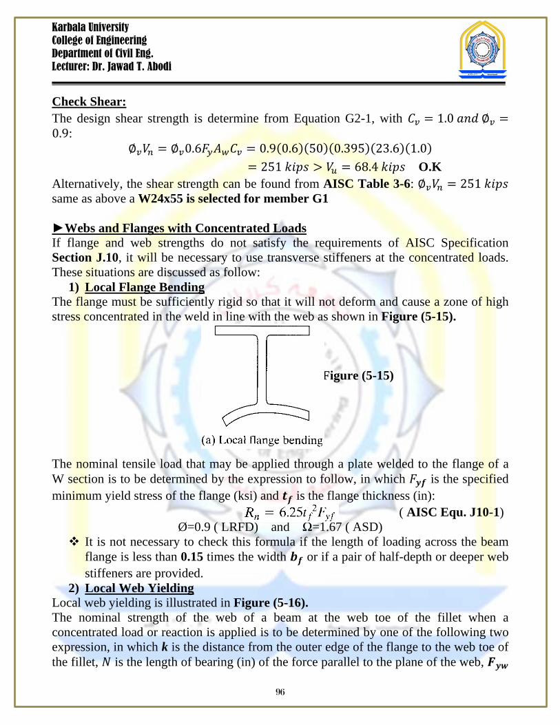
1) Local Flange Bending The flange must be sufficiently rigid so that it will not deform and cause a zone of high stress concentrated in the weld in line with the web as shown in Figure (5-15). Figure (5-15) The nominal tensile load that may be applied through a plate welded to the flange of a W section is to be determined by the expression to follow, in which 𝐹𝒚𝒇 is the specified minimum yield stress of the flange (ksi) and 𝒕𝒇 is the flange thickness (in): ( AISC Equ. J10-1)
Ø=0.9 ( LRFD) and Ω=1.67 ( ASD) It is not necessary to check this formula if the length of loading across the beam
flange is less than 0.15 times the width 𝒃𝒇 or if a pair of half-depth or deeper web stiffeners are provided.
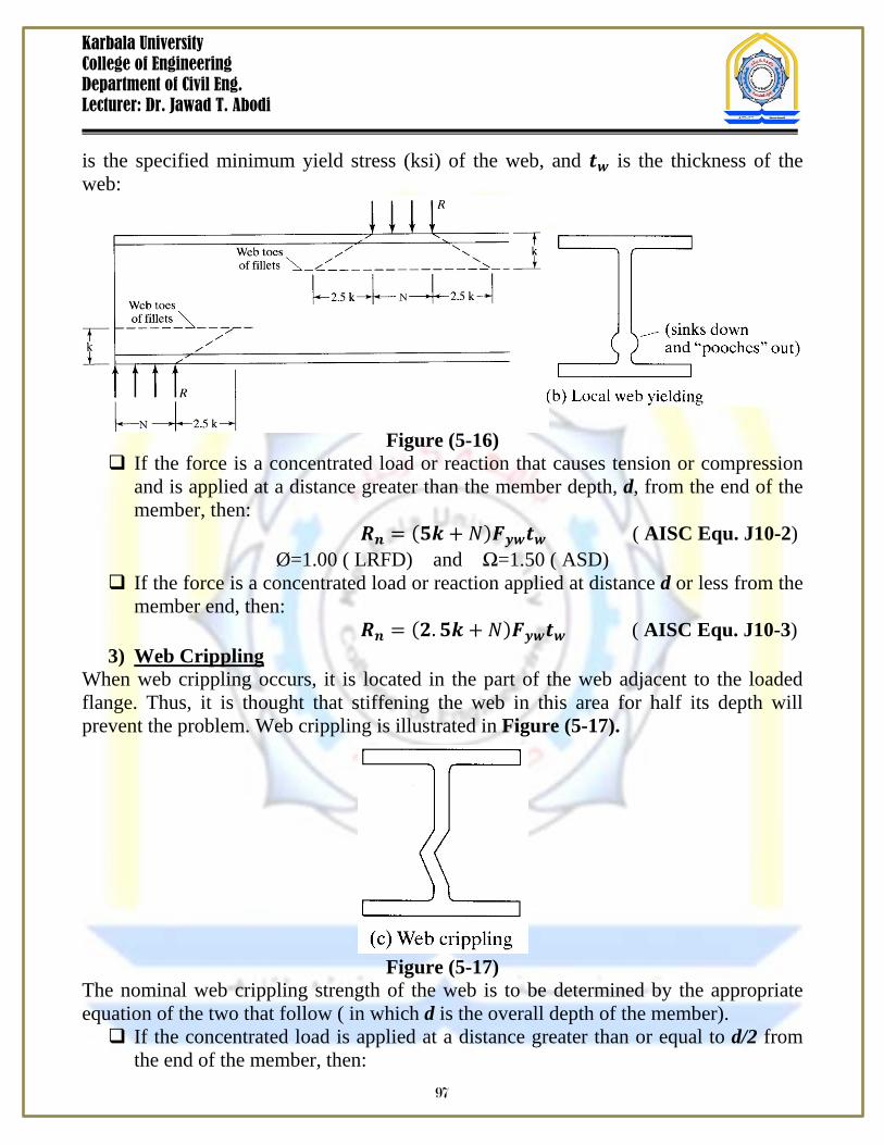
2) Local Web Yielding Local web yielding is illustrated in Figure (5-16). The nominal strength of the web of a beam at the web toe of the fillet when a concentrated load or reaction is applied is to be determined by one of the following two expression, in which k is the distance from the outer edge of the flange to the web toe of the fillet, 𝑁 is the length of bearing (in) of the force parallel to the plane of the web, 𝑭𝒚𝒘
96
Karbala University College of Engineering Department of Civil Eng. Lecturer: Dr. Jawad T. Abodi
is the specified minimum yield stress (ksi) of the web, and 𝒕𝒘 is the thickness of the web:
Figure (5-16) If the force is a concentrated load or reaction that causes tension or compression
and is applied at a distance greater than the member depth, d, from the end of the member, then:
𝑹𝒏 = (𝟓𝒌 + 𝑁)𝑭𝒚𝒘𝒕𝒘 ( AISC Equ. J10-2) Ø=1.00 ( LRFD) and Ω=1.50 ( ASD)
If the force is a concentrated load or reaction applied at distance d or less from the member end, then:
𝑹𝒏 = (𝟐.𝟓𝒌 + 𝑁)𝑭𝒚𝒘𝒕𝒘 ( AISC Equ. J10-3) 3) Web Crippling
When web crippling occurs, it is located in the part of the web adjacent to the loaded flange. Thus, it is thought that stiffening the web in this area for half its depth will prevent the problem. Web crippling is illustrated in Figure (5-17).
Figure (5-17) The nominal web crippling strength of the web is to be determined by the appropriate equation of the two that follow ( in which d is the overall depth of the member). If the concentrated load is applied at a distance greater than or equal to d/2 from
the end of the member, then: 97
Karbala University College of Engineering Department of Civil Eng. Lecturer: Dr. Jawad T. Abodi
( AISC Equ. J10-4)
Ø=0.75 ( LRFD) and Ω=2.00 ( ASD) If the concentrated load is applied at a distance less than d/2 from the end of the
member, then: For 𝑁
𝒅≤ 𝟎.𝟐,
( AISC Equ. J10-5a)
Ø=0.75 ( LRFD) and Ω=2.00 ( ASD) For 𝑁
𝒅> 𝟎.𝟐,
( AISC Equ. J10-5b)
Ø=0.75 ( LRFD) and Ω=2.00 ( ASD) If one or two web stiffeners or one or two doubly plates are provided and extend
for at least half of the web depth, web crippling will not have to be checked.
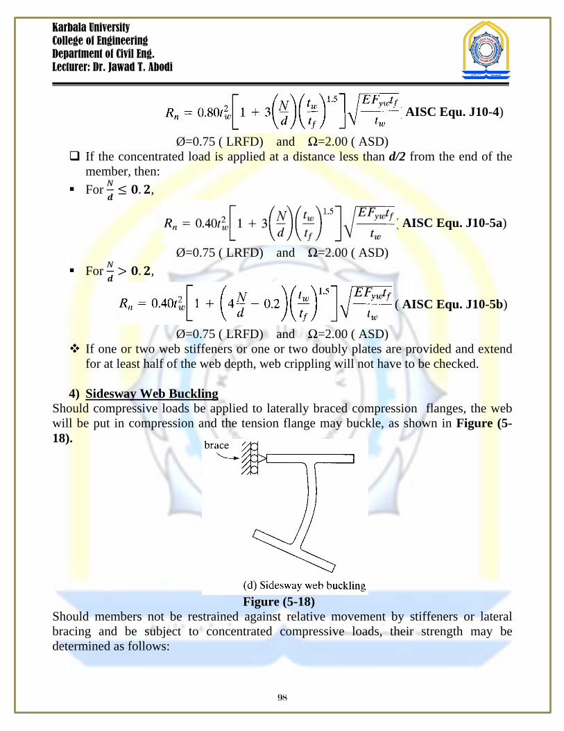
4) Sidesway Web Buckling Should compressive loads be applied to laterally braced compression flanges, the web will be put in compression and the tension flange may buckle, as shown in Figure (5-18). Figure (5-18) Should members not be restrained against relative movement by stiffeners or lateral bracing and be subject to concentrated compressive loads, their strength may be determined as follows:
98
Karbala University College of Engineering Department of Civil Eng. Lecturer: Dr. Jawad T. Abodi
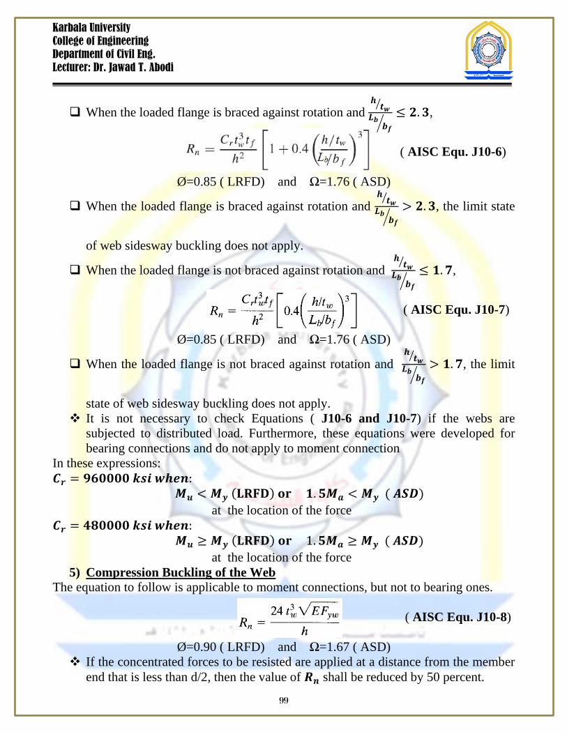
When the loaded flange is braced against rotation and 𝒉𝒕𝒘
𝑳𝒃𝒃𝒇≤ 𝟐.𝟑,
( AISC Equ. J10-6)
Ø=0.85 ( LRFD) and Ω=1.76 ( ASD)
When the loaded flange is braced against rotation and 𝒉𝒕𝒘
𝑳𝒃𝒃𝒇
> 𝟐.𝟑, the limit state
of web sidesway buckling does not apply.
When the loaded flange is not braced against rotation and 𝒉𝒕𝒘
𝑳𝒃𝒃𝒇≤ 𝟏.𝟕,
( AISC Equ. J10-7)
Ø=0.85 ( LRFD) and Ω=1.76 ( ASD)
When the loaded flange is not braced against rotation and 𝒉𝒕𝒘
𝑳𝒃𝒃𝒇
> 𝟏.𝟕, the limit
state of web sidesway buckling does not apply. It is not necessary to check Equations ( J10-6 and J10-7) if the webs are
subjected to distributed load. Furthermore, these equations were developed for bearing connections and do not apply to moment connection
In these expressions: 𝑪𝒓 = 𝟗𝟔𝟎𝟎𝟎𝟎 𝒌𝒔𝒊 𝒘𝒉𝒆𝒏:
𝑴𝒖 < 𝑴𝒚 (𝐋𝐑𝐅𝐃) 𝐨𝐫 𝟏.𝟓𝑴𝒂 < 𝑴𝒚 ( 𝑨𝑺𝑫) at the location of the force 𝑪𝒓 = 𝟒𝟖𝟎𝟎𝟎𝟎 𝒌𝒔𝒊 𝒘𝒉𝒆𝒏:
𝑴𝒖 ≥ 𝑴𝒚 (𝐋𝐑𝐅𝐃) 𝐨𝐫 1.𝟓𝑴𝒂 ≥ 𝑴𝒚 ( 𝑨𝑺𝑫) at the location of the force
5) Compression Buckling of the Web The equation to follow is applicable to moment connections, but not to bearing ones.
( AISC Equ. J10-8)
Ø=0.90 ( LRFD) and Ω=1.67 ( ASD) If the concentrated forces to be resisted are applied at a distance from the member
end that is less than d/2, then the value of 𝑹𝒏 shall be reduced by 50 percent.
99
Karbala University College of Engineering Department of Civil Eng. Lecturer: Dr. Jawad T. Abodi
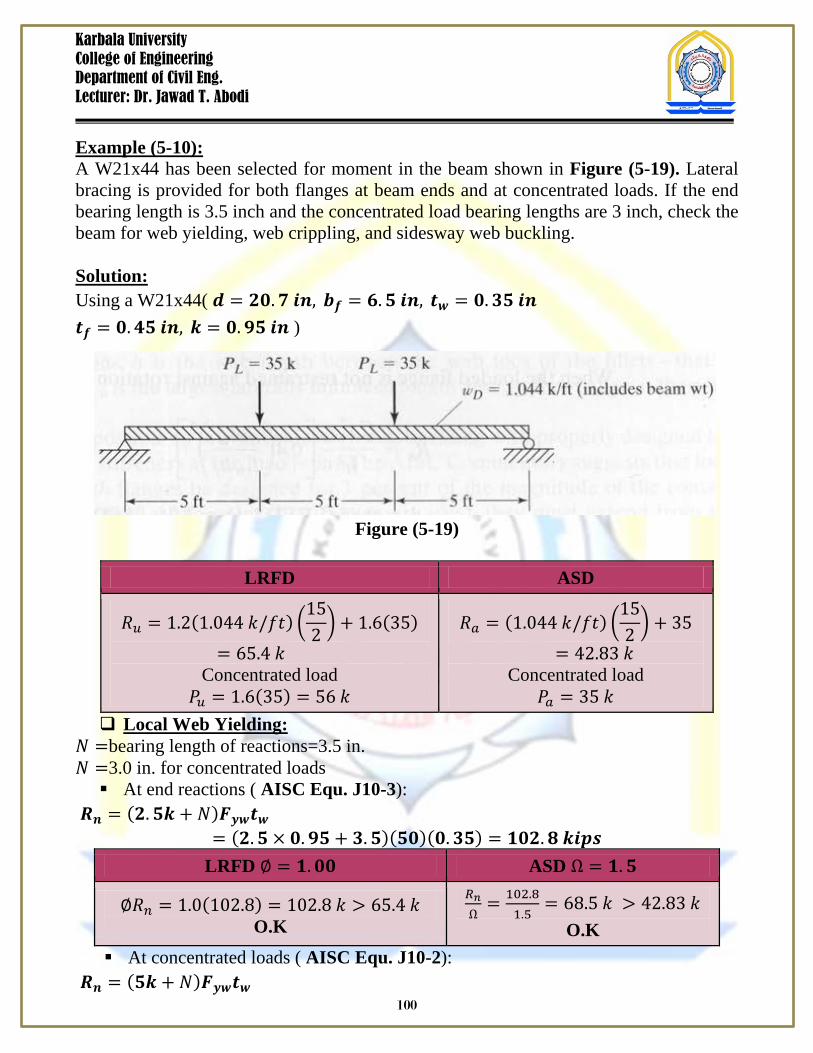
Example (5-10): A W21x44 has been selected for moment in the beam shown in Figure (5-19). Lateral bracing is provided for both flanges at beam ends and at concentrated loads. If the end bearing length is 3.5 inch and the concentrated load bearing lengths are 3 inch, check the beam for web yielding, web crippling, and sidesway web buckling. Solution: Using a W21x44( 𝒅 = 𝟐𝟎.𝟕 𝒊𝒏, 𝒃𝒇 = 𝟔.𝟓 𝒊𝒏, 𝒕𝒘 = 𝟎.𝟑𝟓 𝒊𝒏 𝒕𝒇 = 𝟎.𝟒𝟓 𝒊𝒏, 𝒌 = 𝟎.𝟗𝟓 𝒊𝒏 )
Figure (5-19)
LRFD ASD
𝑅𝑢 = 1.2(1.044 𝑘/𝑓𝑡) 152 + 1.6(35)
= 65.4 𝑘 Concentrated load
𝑃𝑢 = 1.6(35) = 56 𝑘
𝑅𝑎 = (1.044 𝑘/𝑓𝑡) 152 + 35
= 42.83 𝑘 Concentrated load
𝑃𝑎 = 35 𝑘 Local Web Yielding:
𝑁 =bearing length of reactions=3.5 in. 𝑁 =3.0 in. for concentrated loads At end reactions ( AISC Equ. J10-3):
𝑹𝒏 = (𝟐.𝟓𝒌 + 𝑁)𝑭𝒚𝒘𝒕𝒘 = (𝟐.𝟓 × 𝟎.𝟗𝟓 + 𝟑.𝟓)(𝟓𝟎)(𝟎.𝟑𝟓) = 𝟏𝟎𝟐.𝟖 𝒌𝒊𝒑𝒔
LRFD ∅ = 𝟏.𝟎𝟎 ASD Ω = 𝟏.𝟓
∅𝑅𝑛 = 1.0(102.8) = 102.8 𝑘 > 65.4 𝑘 O.K
𝑅𝑛Ω
= 102.81.5
= 68.5 𝑘 > 42.83 𝑘 O.K
At concentrated loads ( AISC Equ. J10-2): 𝑹𝒏 = (𝟓𝒌 + 𝑁)𝑭𝒚𝒘𝒕𝒘
100
Karbala University College of Engineering Department of Civil Eng. Lecturer: Dr. Jawad T. Abodi
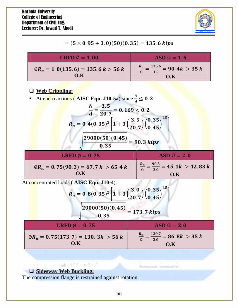
= (𝟓 × 𝟎.𝟗𝟓 + 𝟑.𝟎)(𝟓𝟎)(𝟎.𝟑𝟓) = 𝟏𝟑𝟓.𝟔 𝒌𝒊𝒑𝒔
LRFD ∅ = 𝟏.𝟎𝟎 ASD Ω = 𝟏.𝟓
∅𝑹𝒏 = 𝟏.𝟎(𝟏𝟑𝟓.𝟔) = 𝟏𝟑𝟓.𝟔 𝒌 > 𝟓𝟔 𝒌 O.K
𝑹𝒏Ω
= 𝟏𝟑𝟓.𝟔𝟏.𝟓
= 𝟗𝟎.𝟒𝒌 > 𝟑𝟓 𝒌 O.K
Web Crippling: At end reactions ( AISC Equ. J10-5a) since 𝑁
𝒅≤ 𝟎.𝟐:
𝑁𝒅
=𝟑.𝟓𝟐𝟎.𝟕
= 𝟎.𝟏𝟔𝟗 < 𝟎.𝟐
𝑹𝒏 = 𝟎.𝟒(𝟎.𝟑𝟓)𝟐 𝟏 + 𝟑 𝟑.𝟓𝟐𝟎.𝟕
𝟎.𝟑𝟓𝟎.𝟒𝟓
𝟏.𝟓
𝟐𝟗𝟎𝟎𝟎(𝟓𝟎)(𝟎.𝟒𝟓)𝟎.𝟑𝟓
= 𝟗𝟎.𝟑 𝒌𝒊𝒑𝒔
LRFD ∅ = 𝟎.𝟕𝟓 ASD Ω = 𝟐.𝟎
∅𝑹𝒏 = 𝟎.𝟕𝟓(𝟗𝟎.𝟑) = 𝟔𝟕.𝟕 𝒌 > 𝟔𝟓.𝟒 𝒌 O.K
𝑹𝒏Ω
= 𝟗𝟎.𝟑𝟐.𝟎
= 𝟒𝟓.𝟏𝒌 > 𝟒𝟐.𝟖𝟑 𝒌 O.K
At concentrated loads ( AISC Equ. J10-4):
𝑹𝒏 = 𝟎.𝟖(𝟎.𝟑𝟓)𝟐 𝟏 + 𝟑 𝟑.𝟎𝟐𝟎.𝟕
𝟎.𝟑𝟓𝟎.𝟒𝟓
𝟏.𝟓
𝟐𝟗𝟎𝟎𝟎(𝟓𝟎)(𝟎.𝟒𝟓)𝟎.𝟑𝟓
= 𝟏𝟕𝟑.𝟕 𝒌𝒊𝒑𝒔
LRFD ∅ = 𝟎.𝟕𝟓 ASD Ω = 𝟐.𝟎
∅𝑹𝒏 = 𝟎.𝟕𝟓(𝟏𝟕𝟑.𝟕) = 𝟏𝟑𝟎. 𝟑𝒌 > 𝟓𝟔 𝒌 O.K
𝑹𝒏Ω
= 𝟏𝟑𝟎.𝟕𝟐.𝟎
= 𝟖𝟔.𝟖𝒌 > 𝟑𝟓 𝒌 O.K
Sidesway Web Buckling:
The compression flange is restrained against rotation.
101
Karbala University College of Engineering Department of Civil Eng. Lecturer: Dr. Jawad T. Abodi
𝒉𝒕𝒘
𝒍𝒃𝒃𝒇
=(𝟐𝟎.𝟕 − 𝟐 × 𝟎.𝟗𝟓) 𝟎.𝟑𝟓⁄
𝟓(𝟏𝟐) 𝟔.𝟓⁄ = 𝟓.𝟖𝟐 > 𝟐.𝟑
∴ Sidesway web buckling does not have to be checked The preceding calculations can be appreciably shortened if use is made of the
Manual tables numbered (9-4) and entitled “Beam Bearing Constants”. In these tables, values are shown for ∅𝑹𝟏,∅𝑹𝟐,∅𝑹𝟑, 𝑹𝟏 Ω⁄ ,𝑹𝟐 Ω,𝑹𝟑 Ω⁄⁄ , and so on. The values given represent parts of the equations used for checking web yielding and web crippling and are defined on page 9-19 in the Manual.
Instructions for use of the tables are provided on pages 9-19 and 9-20 of the Manual. Then, those expressions and the table values are used to check the previous calculations.
LRFD ASD
∅𝑹𝒏 = ∅𝑹𝟏 + ∅𝒍𝒃𝑹𝟐 = 𝟒𝟏.𝟔 + 𝟑.𝟓(𝟏𝟕.𝟓)
= 𝟏𝟎𝟐.𝟖 𝒌𝒊𝒑𝒔
𝑹𝒏Ω
=𝑹𝟏Ω
+ 𝒍𝒃 𝑹𝟐Ω
= 𝟐𝟕.𝟕 + 𝟑.𝟓(𝟏𝟏.𝟕) = 𝟔𝟖.𝟔 𝒌𝒊𝒑𝒔
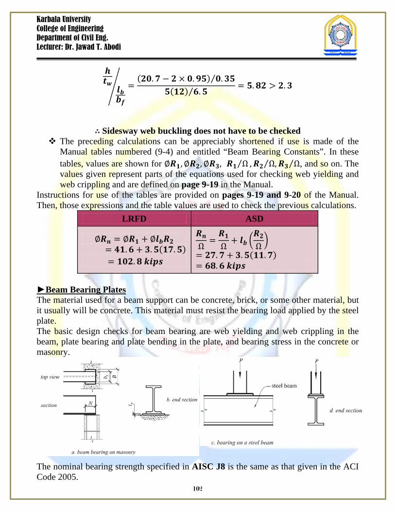
Beam Bearing Plates The material used for a beam support can be concrete, brick, or some other material, but it usually will be concrete. This material must resist the bearing load applied by the steel plate. The basic design checks for beam bearing are web yielding and web crippling in the beam, plate bearing and plate bending in the plate, and bearing stress in the concrete or masonry. The nominal bearing strength specified in AISC J8 is the same as that given in the ACI Code 2005.
102
Karbala University College of Engineering Department of Civil Eng. Lecturer: Dr. Jawad T. Abodi
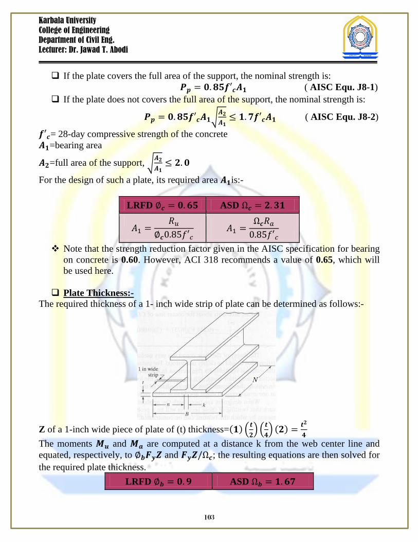
If the plate covers the full area of the support, the nominal strength is:
𝑷𝒑 = 𝟎.𝟖𝟓𝒇′𝒄𝑨𝟏 ( AISC Equ. J8-1) If the plate does not covers the full area of the support, the nominal strength is:
𝑷𝒑 = 𝟎.𝟖𝟓𝒇′𝒄𝑨𝟏𝑨𝟐𝑨𝟏≤ 𝟏.𝟕𝒇′𝒄𝑨𝟏 ( AISC Equ. J8-2)
𝒇′𝒄= 28-day compressive strength of the concrete 𝑨𝟏=bearing area
𝑨𝟐=full area of the support, 𝑨𝟐𝑨𝟏≤ 𝟐.𝟎
For the design of such a plate, its required area 𝑨𝟏is:-
LRFD ∅𝒄 = 𝟎.𝟔𝟓 ASD Ω𝒄 = 𝟐.𝟑𝟏
𝐴1 =𝑅𝑢
∅𝒄0.85𝑓′𝑐 𝐴1 =
Ω𝒄𝑅𝑎0.85𝑓′𝑐
Note that the strength reduction factor given in the AISC specification for bearing on concrete is 0.60. However, ACI 318 recommends a value of 0.65, which will be used here.
Plate Thickness:-
The required thickness of a 1- inch wide strip of plate can be determined as follows:- Z of a 1-inch wide piece of plate of (t) thickness=(𝟏) 𝒕
𝟐 𝒕
𝟒 (𝟐) = 𝒕𝟐
𝟒
The moments 𝑴𝒖 and 𝑴𝒂 are computed at a distance k from the web center line and equated, respectively, to ∅𝒃𝑭𝒚𝒁 and 𝑭𝒚𝒁/Ω𝒄; the resulting equations are then solved for the required plate thickness.
LRFD ∅𝒃 = 𝟎.𝟗 ASD Ω𝒃 = 𝟏.𝟔𝟕
103
Karbala University College of Engineering Department of Civil Eng. Lecturer: Dr. Jawad T. Abodi
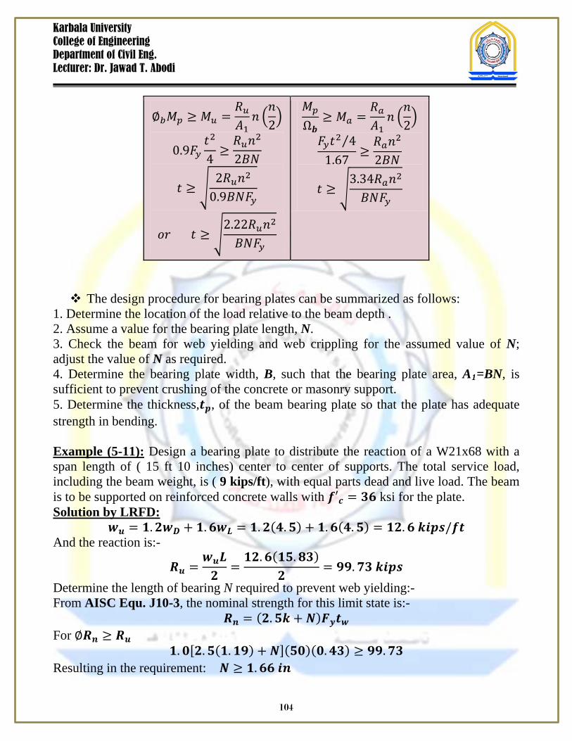
∅𝑏𝑀𝑝 ≥ 𝑀𝑢 =𝑅𝑢𝐴1
𝑛 𝑛2
0.9𝐹𝑦𝑡2
4≥𝑅𝑢𝑛2
2𝐵𝑁
𝑡 ≥ 2𝑅𝑢𝑛2
0.9𝐵𝑁𝐹𝑦
𝑜𝑟 𝑡 ≥ 2.22𝑅𝑢𝑛2
𝐵𝑁𝐹𝑦
𝑀𝑝
Ω𝒃≥ 𝑀𝑎 =
𝑅𝑎𝐴1
𝑛 𝑛2
𝐹𝑦𝑡2 4⁄1.67
≥𝑅𝑎𝑛2
2𝐵𝑁
𝑡 ≥ 3.34𝑅𝑎𝑛2
𝐵𝑁𝐹𝑦
The design procedure for bearing plates can be summarized as follows:
1. Determine the location of the load relative to the beam depth . 2. Assume a value for the bearing plate length, N. 3. Check the beam for web yielding and web crippling for the assumed value of N; adjust the value of N as required. 4. Determine the bearing plate width, B, such that the bearing plate area, A1=BN, is sufficient to prevent crushing of the concrete or masonry support. 5. Determine the thickness,𝒕𝒑, of the beam bearing plate so that the plate has adequate strength in bending. Example (5-11): Design a bearing plate to distribute the reaction of a W21x68 with a span length of ( 15 ft 10 inches) center to center of supports. The total service load, including the beam weight, is ( 9 kips/ft), with equal parts dead and live load. The beam is to be supported on reinforced concrete walls with 𝒇′𝒄 = 𝟑𝟔 ksi for the plate. Solution by LRFD:
𝒘𝒖 = 𝟏.𝟐𝒘𝑫 + 𝟏.𝟔𝒘𝑳 = 𝟏.𝟐(𝟒.𝟓) + 𝟏.𝟔(𝟒.𝟓) = 𝟏𝟐.𝟔 𝒌𝒊𝒑𝒔/𝒇𝒕 And the reaction is:-
𝑹𝒖 =𝒘𝒖𝑳𝟐
=𝟏𝟐.𝟔(𝟏𝟓.𝟖𝟑)
𝟐= 𝟗𝟗.𝟕𝟑 𝒌𝒊𝒑𝒔
Determine the length of bearing N required to prevent web yielding:- From AISC Equ. J10-3, the nominal strength for this limit state is:-
𝑹𝒏 = (𝟐.𝟓𝒌 + 𝑵)𝑭𝒚𝒕𝒘 For ∅𝑹𝒏 ≥ 𝑹𝒖
𝟏.𝟎[𝟐.𝟓(𝟏.𝟏𝟗) + 𝑵](𝟓𝟎)(𝟎.𝟒𝟑) ≥ 𝟗𝟗.𝟕𝟑 Resulting in the requirement: 𝑵 ≥ 𝟏.𝟔𝟔 𝒊𝒏
104
Karbala University College of Engineering Department of Civil Eng. Lecturer: Dr. Jawad T. Abodi
Use AISC Equ. J10-5 to determine the value of N required to prevent web crippling. Assuming 𝑵/𝒅 > 𝟎.𝟐 and try the second form of the equation, J10-5b. For ∅𝑹𝒏 ≥ 𝑹𝒖
𝟎.𝟕𝟓(𝟎.𝟒)(0.𝟒𝟑)𝟐 𝟏 + 𝟒𝑵𝟐𝟏.𝟏
− 𝟎.𝟐 𝟎.𝟒𝟑𝟎.𝟔𝟖𝟓
𝟏.𝟓
𝟐𝟗𝟎𝟎𝟎(𝟓𝟎)(𝟎.𝟔𝟖𝟓)𝟎.𝟒𝟑
≥ 𝟗𝟗.𝟕𝟑
This results in the requirement: 𝑵 ≥ 𝟑.𝟎 𝒊𝒏 Check the assumption:
𝑵𝒅
=𝟑
𝟐𝟏.𝟏= 𝟎.𝟏𝟒 < 𝟎.𝟐 𝑵.𝑮
For 𝑵/𝒅 ≤ 𝟎.𝟐, use AISC Equ. J10-5a: For ∅𝑹𝒏 ≥ 𝑹𝒖
𝟎.𝟕𝟓(𝟎.𝟒)(𝟎.𝟒𝟑)𝟐 𝟏 + 𝟑
𝑵𝟐𝟏.𝟏
𝟎.𝟒𝟑𝟎.𝟔𝟖𝟓
𝟏.𝟓
𝟐𝟗𝟎𝟎𝟎(𝟓𝟎)(𝟎.𝟔𝟖𝟓)𝟎.4𝟑
≥ 𝟗𝟗.𝟕𝟑
Resulting in the requirement: 𝑵 ≥ 𝟐.𝟓𝟗 𝒊𝒏, and 𝑵𝒅
=𝟐.𝟓𝟗𝟐𝟏.𝟏
= 𝟎.𝟏𝟐 < 𝟎.𝟐 𝑶.𝑲 Try N=6 in. determine dimension B from a consideration of bearing strength. If we conservatively, assume that the full area of the support is used, the required plate area 𝑨𝟏 can be found as follows:-
∅𝒄𝑷𝒑 ≥ 𝑹𝒖 From AISC Equ. J8-1, 𝑷𝒑 = 𝟎.𝟖𝟓𝒇′𝒄𝑨𝟏. then,
∅𝒄(𝟎.𝟖𝟓𝒇′𝒄𝑨𝟏) ≥ 𝑹𝒖 𝟎.𝟔𝟓(𝟎.𝟖𝟓)(𝟑.𝟓)𝑨𝟏 ≥ 𝟗𝟗.𝟕𝟑
𝑨𝟏 ≥ 𝟓𝟏.𝟓𝟕 𝒊𝒏𝟐 The min. value of dimension B is:-
𝑩 =𝑨𝟏𝑵
=𝟓𝟏.𝟓𝟕𝟔
= 𝟖.𝟔 𝒊𝒏 > 𝒃𝒇 = 𝟖.𝟐𝟕 (𝑩 ≥ 𝒃𝒇) Try B=10 in., then compute the required plate thickness:-
105
Karbala University College of Engineering Department of Civil Eng. Lecturer: Dr. Jawad T. Abodi
𝒏 =𝑩 − 𝟐𝒌
𝟐=𝟏𝟎 − 𝟐(𝟏.𝟏𝟗)
𝟐= 𝟑.𝟖𝟏 𝒊𝒏
𝑡 = 2.22𝑅𝑢𝑛2
𝐵𝑁𝐹𝑦=
2.22(99.73)(3.81)2
10(6)(36) = 1.22 𝑖𝑛
Use a PL 𝟏𝟏 𝟒 × 𝟔 × 𝟏𝟎
If we were to check to see if the flange thickness alone is sufficient, we would
have 𝑛 = 𝑏𝑓2 − 𝑘 = 8.27
2 − 1.19 = 2.95 𝑖𝑛
𝑡 = 2.22𝑅𝑢𝑛2
𝐵𝑁𝐹𝑦= 2.22(99.73)(2.95)2
8.27(6)(36) = 1.04 𝑖𝑛 > 𝑡𝑓 𝑵.𝑮
106


![Sham'e Karbala [Urdu]](https://img.pdfslide.us/doc/110x75/577cd6981a28ab9e789cbd41/shame-karbala-urdu.jpg)


![Bloodshed in Karbala [English]](https://img.pdfslide.us/doc/110x75/577cde171a28ab9e78ae5e6a/bloodshed-in-karbala-english.jpg)