Embed Size (px)
Citation preview
1
INTRODUCTION The word ELECTRICITY is derived from the Greek word ELECTRON, meaning amber. This is due to the fact that you can create static electricity by rubbing a piece of amber with a cloth, so the word is actually describing a phenomenon. A lot of the forthcoming theory is based on these physical phenomenons’s, which you all know. Remember that the contents of this course are more or less used in most appliances and tools that you handle on a daily basis. Think about the fact that today we all take electricity for granted, how much we all rely on the electricity. You are required to have the knowledge of some basic mathematics. We won’t go much into the mathematics but we will perform some calculations based on simple algebra. There will also be some basic trigonometry. The purpose of this course is to give you an insight into the basic electricity. You will learn the difference between AC and DC. How you can read an electric diagram and how to make a diagram. You will also learn the function of the different components in an electric circuit. Finally you will learn how to use the different tools and the safety aspects and rules when working on an electric circuit or machinery. In conjunction with this material you will also do some practical exercises that will support the theory in these papers. We hope that You will learn, enjoy and gain knowledge from this course, that You can put into practical use in Your future activities.
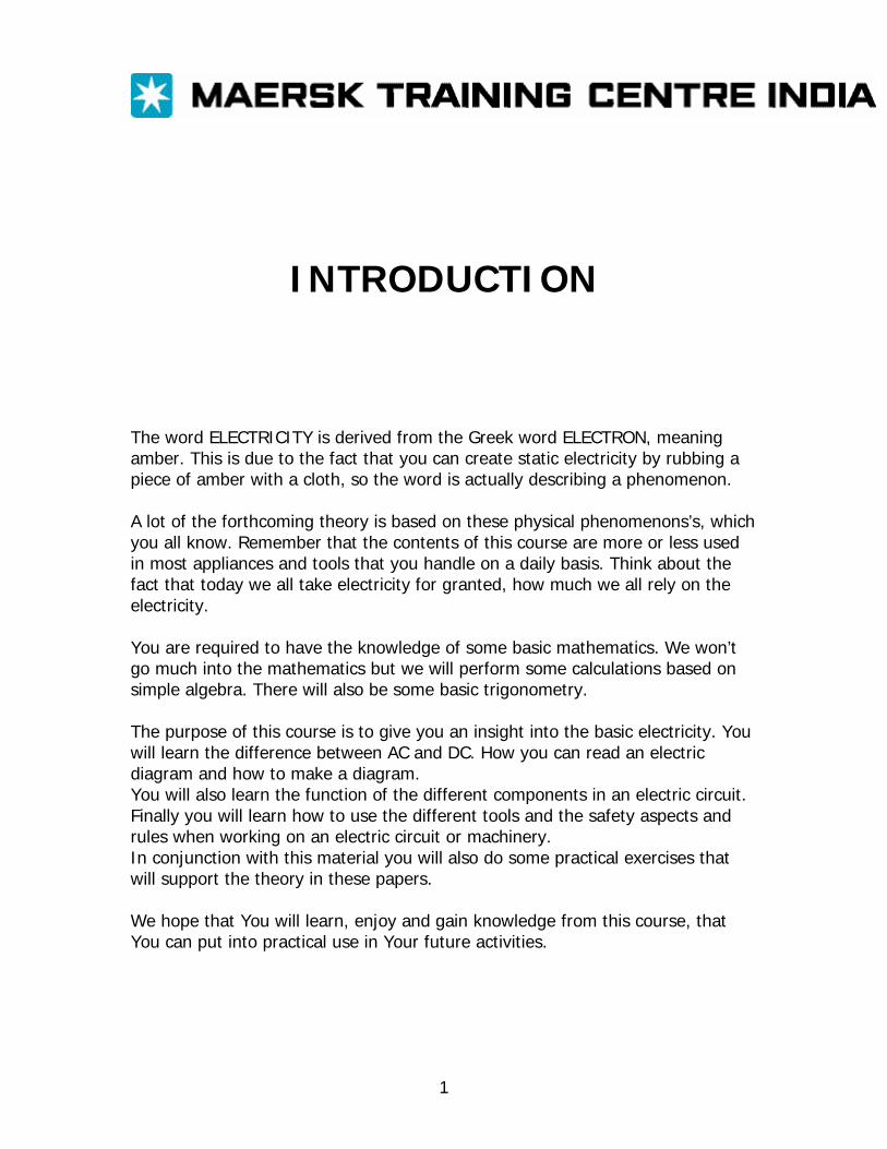
BASIC ELECTRICITY In this chapter we are going to address the issues of what electricity is and how it is generated. What are voltage, current, resistance and power? ELECTRICITY: Imagine a piece of wire. In the one end of that piece of wire you attach a voltage with a high potential, like the positive end of a battery. What happens? Nothing! Nothing will happen until you connect another potential that is related with the first potential that you connected, like the negative end of the same battery. Thus you have a CIRCUIT, and when you have a circuit with two different potentials, you will have a CURRENT of electrons flowing. So we have to have a closed circuit to have a current flowing. Normally we say that the current flows from the positive (highest) to the negative (lowest) potential, but actually it is the other way round. The current consists of free electrons flowing from the negative (lowest) potential to the positive (highest) potential, as electrons are negatively charged. You could say that the negative end has a surplus of free electrons and that the positive end lacks electrons. So just like a magnet where you have a positive end and a negative end that attracts each other, the positive potential attracts the negative electrons. The difference between the two potentials is called VOLTAGE. On the next page the above is shown schematically.
Normal flow Circuit Flow direction direction of electrons + - High potential Low potential Battery The difference being called the VOLTAGE
The above diagram is showing a state that is normally referred to as a SHORT CURCUIT. The reason being that there is no restriction to the flow of electrons. This restriction is called RESISTANCE. Now we have already introduced some terms that we call units so let’s take a closer look at those units. UNITS: VOLTAGE: Voltage is measured in Volts, the abbreviation being V. A normal battery has a voltage of 1.5 Volts. Volts are denoted with a V. CURRENT: Current is measured in Amperes, the abbreviation being A. The intensity of current depends of the voltage applied and the resistance present in the circuit, according to Ohm’s law. Amperes are denoted with an I.
RESISTANCE: Resistance is measured in Ohms, the abbreviation being the Greek letter omega, Ω. The resistance in an object (circuit) is normally constant, but can alter with the ambient temperature. Ohms are denoted with a R. The correlation between Volts, Amperes and Ohms are best described in Ohm’s law;
V = I * R POWER: Power is measured in Watts, the abbreviation being W. Power is the given amount of energy per time unit and is a measurement of the size of the device. Power is denoted with a P. The correlation between Power, Voltage, Current and Resistance can be described as such (the power sentence);
P = V * I
And as Ohm’s law is like this;
V = I * R
You can rewrite the first sentence as follows;
P = I * R * I
which gives us
P = I2 * R
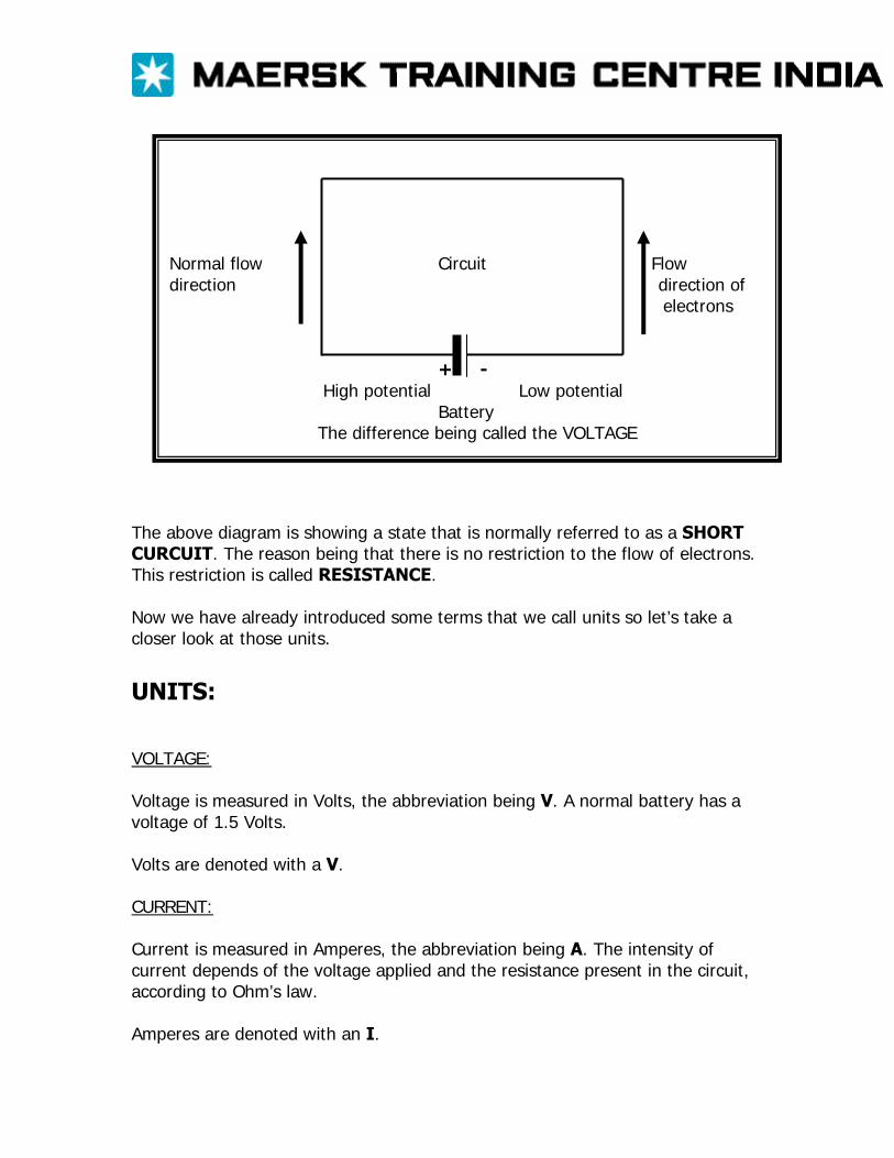
Most appliances contain a resistance, like a light bulb. When an appliance is connected in a circuit, it is often referred to as a LOAD. In other words most loads contain a resistance. If we insert a load in the diagram that we have already made, we get the below diagram.
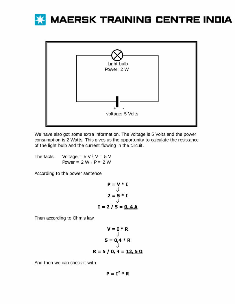
Light bulb Power: 2 W + - voltage: 5 Volts
We have also got some extra information. The voltage is 5 Volts and the power consumption is 2 Watts. This gives us the opportunity to calculate the resistance of the light bulb and the current flowing in the circuit. The facts: Voltage = 5 V ⎝ V = 5 V Power = 2 W ⎝ P = 2 W According to the power sentence
P = V * I ⇓
2 = 5 * I ⇓
I = 2 / 5 = 0, 4 A Then according to Ohm’s law
V = I * R ⇓
5 = 0,4 * R ⇓
R = 5 / 0, 4 = 12, 5 Ω And then we can check it with
P = I2 * R
⇓ P = 0, 4 * 0, 4 * 12, 5 = 2 W
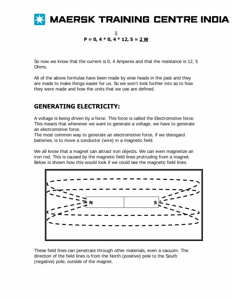
So now we know that the current is 0, 4 Amperes and that the resistance is 12, 5 Ohms. All of the above formulas have been made by wise heads in the past and they are made to make things easier for us. So we won’t look further into as to how they were made and how the units that we use are defined. GENERATING ELECTRICITY: A voltage is being driven by a force. This force is called the Electromotive force. This means that whenever we want to generate a voltage, we have to generate an electromotive force. The most common way to generate an electromotive force, if we disregard batteries, is to move a conductor (wire) in a magnetic field. We all know that a magnet can attract iron objects. We can even magnetize an iron rod. This is caused by the magnetic field lines protruding from a magnet. Below is shown how this would look if we could see the magnetic field lines.
N S
These field lines can penetrate through other materials, even a vacuum. The direction of the field lines is from the North (positive) pole to the South (negative) pole, outside of the magnet.
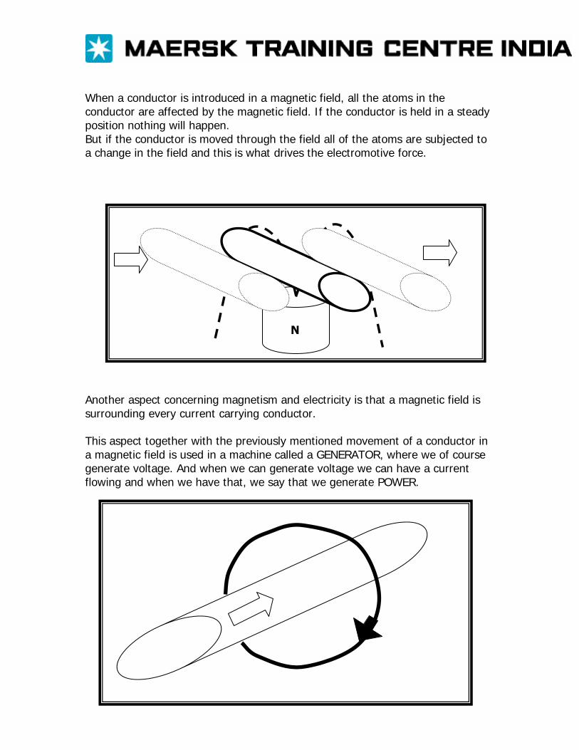
When a conductor is introduced in a magnetic field, all the atoms in the conductor are affected by the magnetic field. If the conductor is held in a steady position nothing will happen. But if the conductor is moved through the field all of the atoms are subjected to a change in the field and this is what drives the electromotive force.
N
Another aspect concerning magnetism and electricity is that a magnetic field is surrounding every current carrying conductor. This aspect together with the previously mentioned movement of a conductor in a magnetic field is used in a machine called a GENERATOR, where we of course generate voltage. And when we can generate voltage we can have a current flowing and when we have that, we say that we generate POWER.
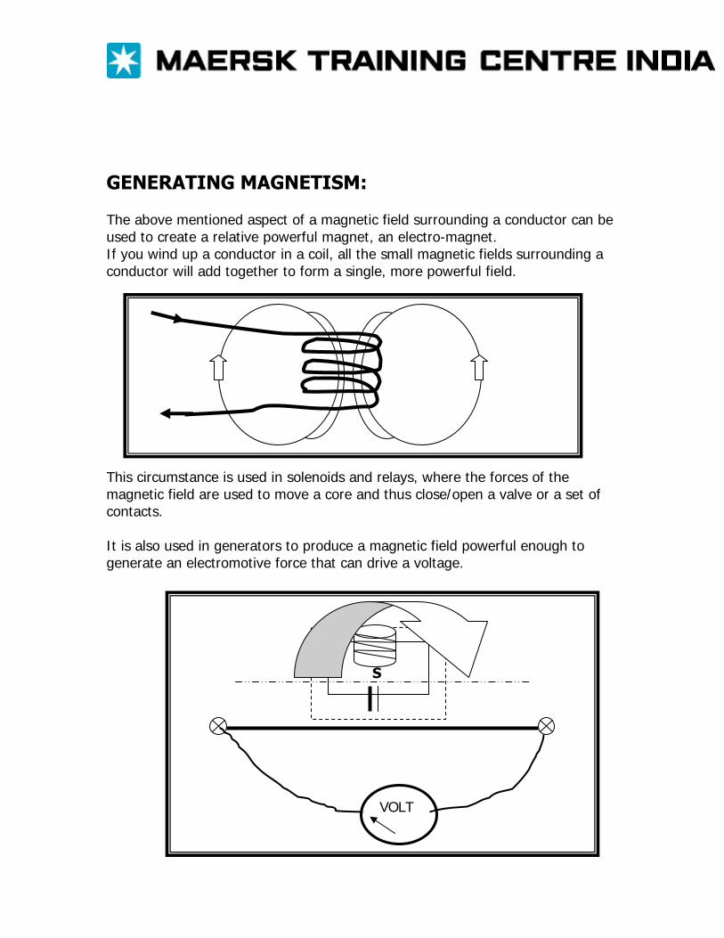
GENERATING MAGNETISM: The above mentioned aspect of a magnetic field surrounding a conductor can be used to create a relative powerful magnet, an electro-magnet. If you wind up a conductor in a coil, all the small magnetic fields surrounding a conductor will add together to form a single, more powerful field.
This circumstance is used in solenoids and relays, where the forces of the magnetic field are used to move a core and thus close/open a valve or a set of contacts. It is also used in generators to produce a magnetic field powerful enough to generate an electromotive force that can drive a voltage.
N
VOLT
S

ATOMS AND IONS: An atom consists of a nucleus and around that nucleus electrons are orbiting. The nucleus consists of neutral neutrons and positive protons. The electrons are negative. Normally there is a balance between the number of positive protons and negative electrons so if you see the atom as a whole, it is neutral. If, for some reason, the atom loses one or more of the electrons, there is a surplus of positive charges and if you see the atom as a whole it will be positive. The electrons that the atom has lost will be attached to another atom, which will then have a surplus of negative charges and if you see that atom as a whole, it will be negative. These positive and negative atoms are called ions. We can chemically create ions, it is very easy. Just take ordinary salt, NaCl (Sodium chloride) and dissolve it in water. The Sodium atom will be split from the Chloride atom and then you have a positive Sodium ion and a negative Chloride ion. This goes for all acids, bases (alkalines) and salts. BATTERIES: These circumstances are used in wet batteries to create a high potential and a low potential. And if you haven’t forgotten, the difference between a high and a low potential is what we call the voltage and when we have a voltage and a circuit we can have a current flowing. Let’s take Sulphuric acid (H2SO4) and dissolve it in water. Then we get Hydrogen ions and Sulphuric ions in the water. If we then enter a zinc rod and a copper rod into the solution and connect a voltmeter we will be able to get a reading on the volt meter. That is because zinc and copper has different capabilities to create positive ions. That capability is referred to as electropositivity and metals can be arranged according to their electropositivity into the electromotive series. And as zinc is more electropositive than copper, electrons will flow from the zinc to the copper through the volt meter, as the sulphuric ions, which are negative, are attracted to the positive zinc. When these two components interact, they release electrons. It is these electrons that flow through the volt meter. At the copper rod the hydrogen ions receive electrons and create free hydrogen.
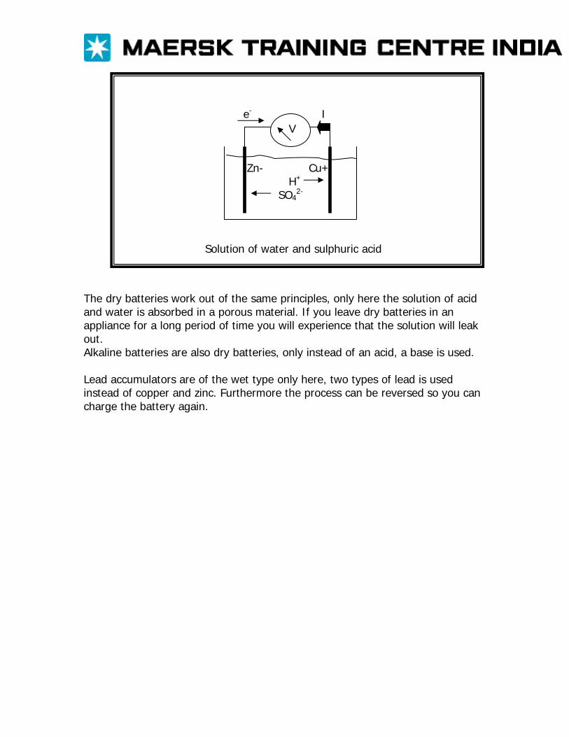
e- I Zn- Cu+ H+
SO42-
Solution of water and sulphuric acid
V
The dry batteries work out of the same principles, only here the solution of acid and water is absorbed in a porous material. If you leave dry batteries in an appliance for a long period of time you will experience that the solution will leak out. Alkaline batteries are also dry batteries, only instead of an acid, a base is used. Lead accumulators are of the wet type only here, two types of lead is used instead of copper and zinc. Furthermore the process can be reversed so you can charge the battery again.
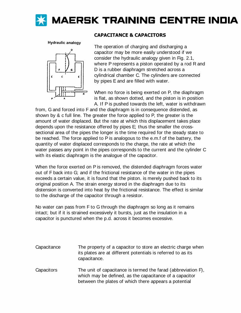
CAPACITANCE & CAPACITORS The operation of charging and discharging a capacitor may be more easily understood if we consider the hydraulic analogy given in Fig. 2.1, where P represents a piston operated by a rod R and D is a rubber diaphragm stretched across a cylindrical chamber C. The cylinders are connected by pipes E and are filled with water. When no force is being exerted on P, the diaphragm is flat, as shown dotted, and the piston is in position A. If P is pushed towards the left, water is withdrawn
from, G and forced into F and the diaphragm is in consequence distended, as shown by & c full line. The greater the force applied to P, the greater is the amount of water displaced. But the rate at which this displacement takes place depends upon the resistance offered by pipes E; thus the smaller the cross-sectional area of the pipes the longer is the time required for the steady state to be reached. The force applied to P is analogous to the e.m.f of the battery, the quantity of water displaced corresponds to the charge, the rate at which the water passes any point in the pipes corresponds to the current and the cylinder C with its elastic diaphragm is the analogue of the capacitor. When the force exerted on P is removed, the distended diaphragm forces water out of F back into G; and if the frictional resistance of the water in the pipes exceeds a certain value, it is found that the piston. is merely pushed back to its original position A. The strain energy stored in the diaphragm due to its distension is converted into heat by the frictional resistance. The effect is similar to the discharge of the capacitor through a resistor. No water can pass from F to G through the diaphragm so long as it remains intact; but if it is strained excessively it bursts, just as the insulation in a capacitor is punctured when the p.d. across it becomes excessive. Capacitance The property of a capacitor to store an electric charge when
its plates are at different potentials is referred to as its capacitance.
Capacitors The unit of capacitance is termed the farad (abbreviation F), which may be defined, as the capacitance of a capacitor between the plates of which there appears a potential

difference of 1 volt when it is charged by 1 coulomb of electricity.
It follows from the definition of the farad that Charge [coulombs] = capacitance [farads] Applied p.d [volts]
Paper-insulated capacitor Or in symbols; Q /V = C Therefore Q = CV coulombs In practice, the farad is found to be inconveniently large and
the capacitance is usually expressed in microfarads (µF) or in picofarads (pF), where
1µF=1O-6 F and 1pF=10-12F
INDUCTANCE The unit of inductance is termed the henry, in commemoration of a famous American physicist, Joseph Henry (1797-1878), who, quite independently, discovered electromagnetic induction within a year after it had been discovered in Britain by Michael Faraday in 1831. A circuit has an inductance; of 1 henry (or 1 H) if an e.m.f. of 1 volt is induced in the circuit when the current varies uniformly at the rate of 1 ampere per second. If either the inductance or the rate of change of current is doubled the induced e.m.f. is doubled. Hence if a circuit has an inductance of L henrys and if the current increases from i1 to i2 amperes in t seconds the average rate of change of current is (i2-i1) / t amperes per second and average induced e.m.f. is
L x rate of change of current = L x (i2-i1) / t volts Or e = L x di/dt
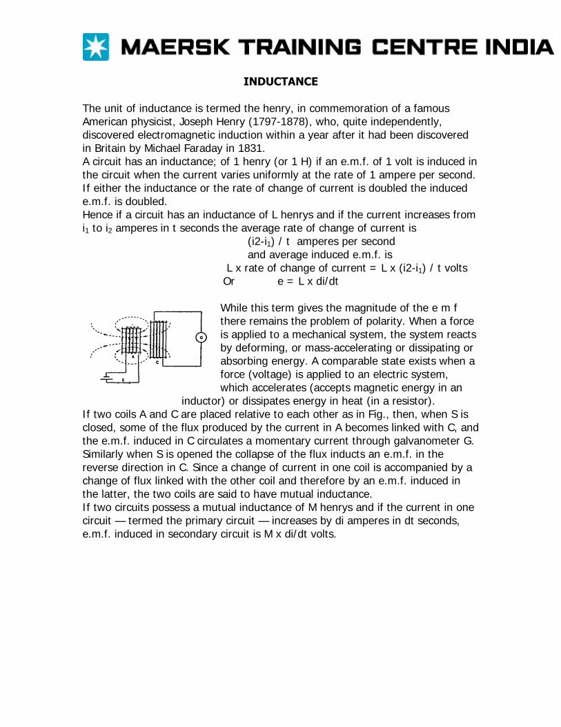
While this term gives the magnitude of the e m f there remains the problem of polarity. When a force is applied to a mechanical system, the system reacts by deforming, or mass-accelerating or dissipating or absorbing energy. A comparable state exists when a force (voltage) is applied to an electric system, which accelerates (accepts magnetic energy in an
inductor) or dissipates energy in heat (in a resistor). If two coils A and C are placed relative to each other as in Fig., then, when S is closed, some of the flux produced by the current in A becomes linked with C, and the e.m.f. induced in C circulates a momentary current through galvanometer G. Similarly when S is opened the collapse of the flux inducts an e.m.f. in the reverse direction in C. Since a change of current in one coil is accompanied by a change of flux linked with the other coil and therefore by an e.m.f. induced in the latter, the two coils are said to have mutual inductance. If two circuits possess a mutual inductance of M henrys and if the current in one circuit — termed the primary circuit — increases by di amperes in dt seconds, e.m.f. induced in secondary circuit is M x di/dt volts.
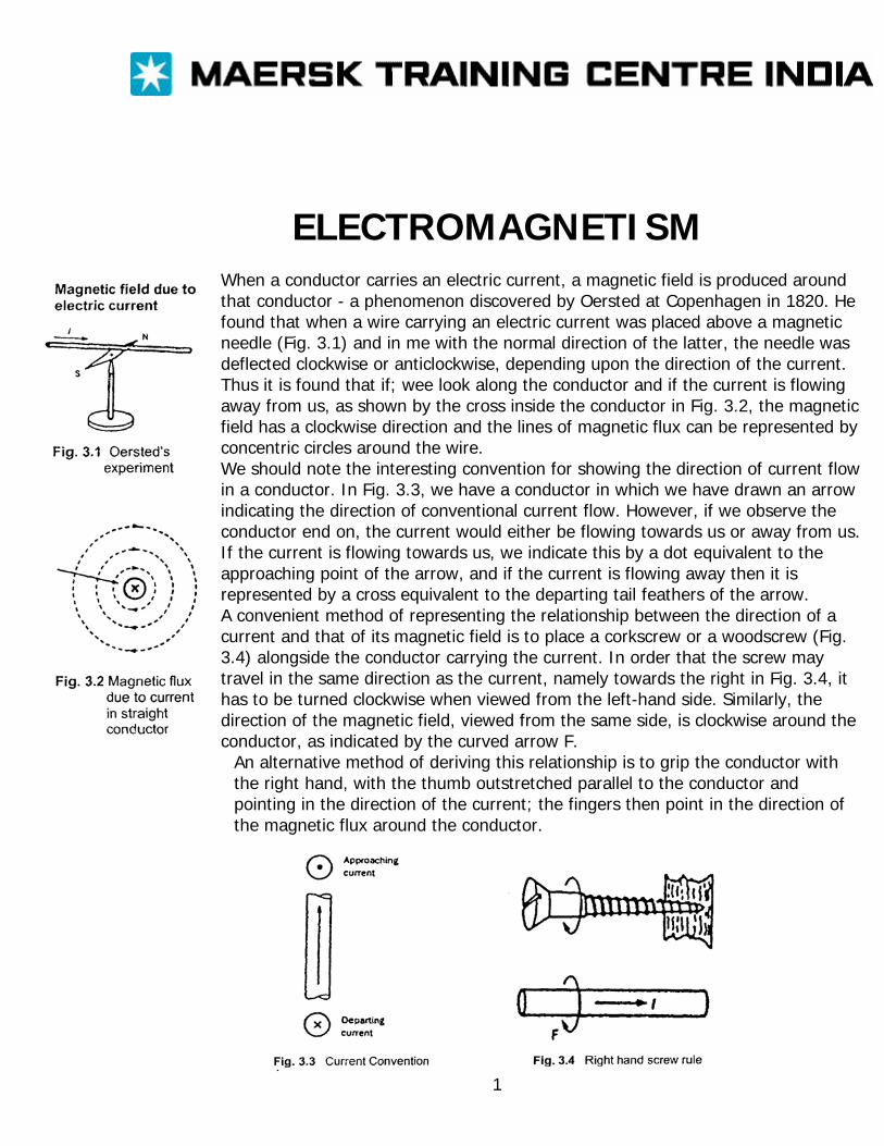
ELECTROMAGNETISM When a conductor carries an electric current, a magnetic field is produced around that conductor - a phenomenon discovered by Oersted at Copenhagen in 1820. He found that when a wire carrying an electric current was placed above a magnetic needle (Fig. 3.1) and in me with the normal direction of the latter, the needle was deflected clockwise or anticlockwise, depending upon the direction of the current. Thus it is found that if; wee look along the conductor and if the current is flowing away from us, as shown by the cross inside the conductor in Fig. 3.2, the magnetic field has a clockwise direction and the lines of magnetic flux can be represented by concentric circles around the wire. We should note the interesting convention for showing the direction of current flow in a conductor. In Fig. 3.3, we have a conductor in which we have drawn an arrow indicating the direction of conventional current flow. However, if we observe the conductor end on, the current would either be flowing towards us or away from us. If the current is flowing towards us, we indicate this by a dot equivalent to the approaching point of the arrow, and if the current is flowing away then it is represented by a cross equivalent to the departing tail feathers of the arrow. A convenient method of representing the relationship between the direction of a current and that of its magnetic field is to place a corkscrew or a woodscrew (Fig. 3.4) alongside the conductor carrying the current. In order that the screw may travel in the same direction as the current, namely towards the right in Fig. 3.4, it has to be turned clockwise when viewed from the left-hand side. Similarly, the direction of the magnetic field, viewed from the same side, is clockwise around the conductor, as indicated by the curved arrow F.
An alternative method of deriving this relationship is to grip the conductor with the right hand, with the thumb outstretched parallel to the conductor and pointing in the direction of the current; the fingers then point in the direction of the magnetic flux around the conductor.
1
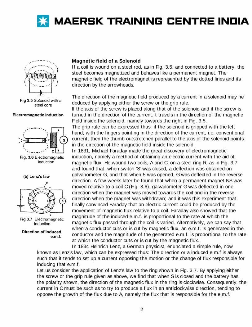
Magnetic field of a Solenoid If a coil is wound on a steel rod, as in Fig. 3.5, and connected to a battery, the steel becomes magnetized and behaves like a permanent magnet. The magnetic field of the electromagnet is represented by the dotted lines and its direction by the arrowheads. The direction of the magnetic field produced by a current in a solenoid may he deduced by applying either the screw or the grip rule. lf the axis of the screw is placed along that of the solenoid and if the screw is turned in the direction of the current, t travels in the direction of the magnetic Field inside the solenoid, namely towards the right in Fig. 3.5. The grip rule can be expressed thus: if the solenoid is gripped with the left hand, with the fingers pointing in the direction of the current, i.e. conventional current, then the thumb outstretched parallel to the axis of the solenoid points in the direction of the magnetic field inside the solenoid. In 1831, Michael Faraday made the great discovery of electromagnetic induction, namely a method of obtaining an electric current with the aid of magnetic flux. He wound two coils, A and C, on a steel ring R, as in Fig. 3.7 and found that, when switch ‘S’ was closed, a deflection was obtained on galvanometer G, and that when 5 was opened, G was deflected in the reverse direction. A few weeks later he found that when a permanent magnet NS was moved relative to a coil C (Fig. 3.6), galvanometer G was deflected in one direction when the magnet was moved towards the coil and in the reverse direction when the magnet was withdrawn; and it was this experiment that finally convinced Faraday that an electric current could be produced by the movement of magnetic flux relative to a coil. Faraday also showed that the magnitude of the induced e.m.f. is proportional to the rate at which the magnetic flux passed through the coil is varied. Alternatively, we can say that when a conductor cuts or is cut by magnetic flux, an e.m.f. is generated in the conductor and the magnitude of the generated e.m.f. is proportional to the rate at which the conductor cuts or is cut by the magnetic flux. In 1834 Heinrich Lenz, a German physicist, enunciated a simple rule, now
known as Lenz’s law, which can be expressed thus: The direction or a induced e.m.f is always such that it tends to set up a current opposing the motion or the change of flux responsible for inducing that e.m.f. Let us consider the application of Lenz’s law to the ring shown in Fig. 3.7. By applying either the screw or the grip rule given as above, we find that when S is closed and the battery has the polarity shown, the direction of the magnetic flux in the ring is clockwise. Consequently, the current in C must be such as to try to produce a flux in an anticlockwise direction, tending to oppose the growth of the flux due to A, namely the flux that is responsible for the e.m.f.
2
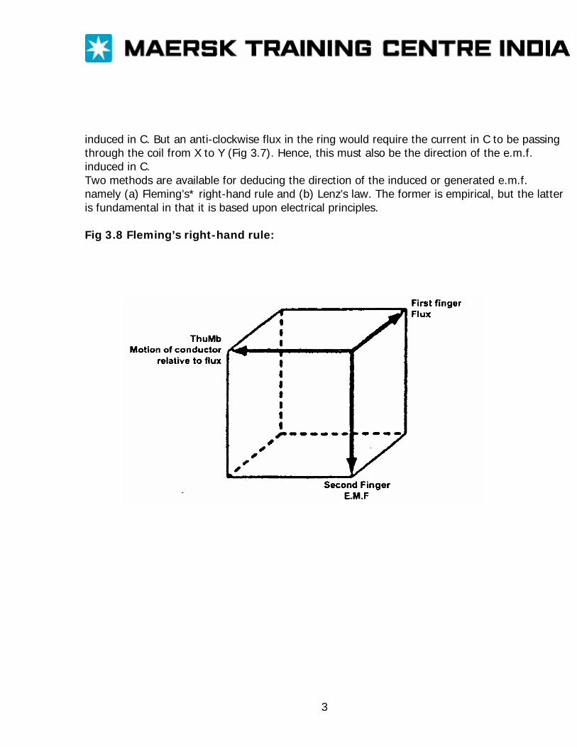
induced in C. But an anti-clockwise flux in the ring would require the current in C to be passing through the coil from X to Y (Fig 3.7). Hence, this must also be the direction of the e.m.f. induced in C. Two methods are available for deducing the direction of the induced or generated e.m.f. namely (a) Fleming’s* right-hand rule and (b) Lenz’s law. The former is empirical, but the latter is fundamental in that it is based upon electrical principles. Fig 3.8 Fleming’s right-hand rule:
3
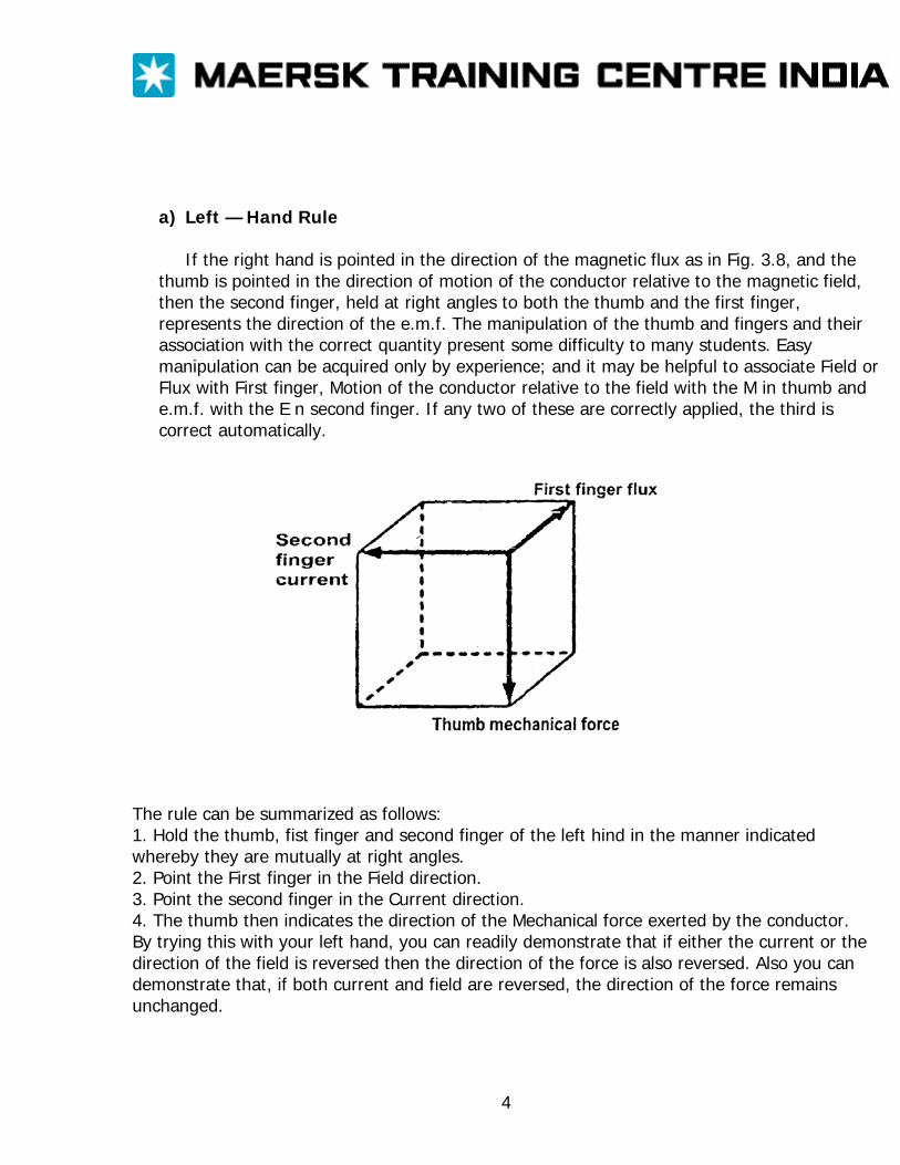
a) Left — Hand Rule If the right hand is pointed in the direction of the magnetic flux as in Fig. 3.8, and the
thumb is pointed in the direction of motion of the conductor relative to the magnetic field, then the second finger, held at right angles to both the thumb and the first finger, represents the direction of the e.m.f. The manipulation of the thumb and fingers and their association with the correct quantity present some difficulty to many students. Easy manipulation can be acquired only by experience; and it may be helpful to associate Field or Flux with First finger, Motion of the conductor relative to the field with the M in thumb and e.m.f. with the E n second finger. If any two of these are correctly applied, the third is correct automatically.
The rule can be summarized as follows: 1. Hold the thumb, fist finger and second finger of the left hind in the manner indicated whereby they are mutually at right angles. 2. Point the First finger in the Field direction. 3. Point the second finger in the Current direction. 4. The thumb then indicates the direction of the Mechanical force exerted by the conductor. By trying this with your left hand, you can readily demonstrate that if either the current or the direction of the field is reversed then the direction of the force is also reversed. Also you can demonstrate that, if both current and field are reversed, the direction of the force remains unchanged.
4
ALTERNATING CURRENT 3-PHASE VOLTAGE
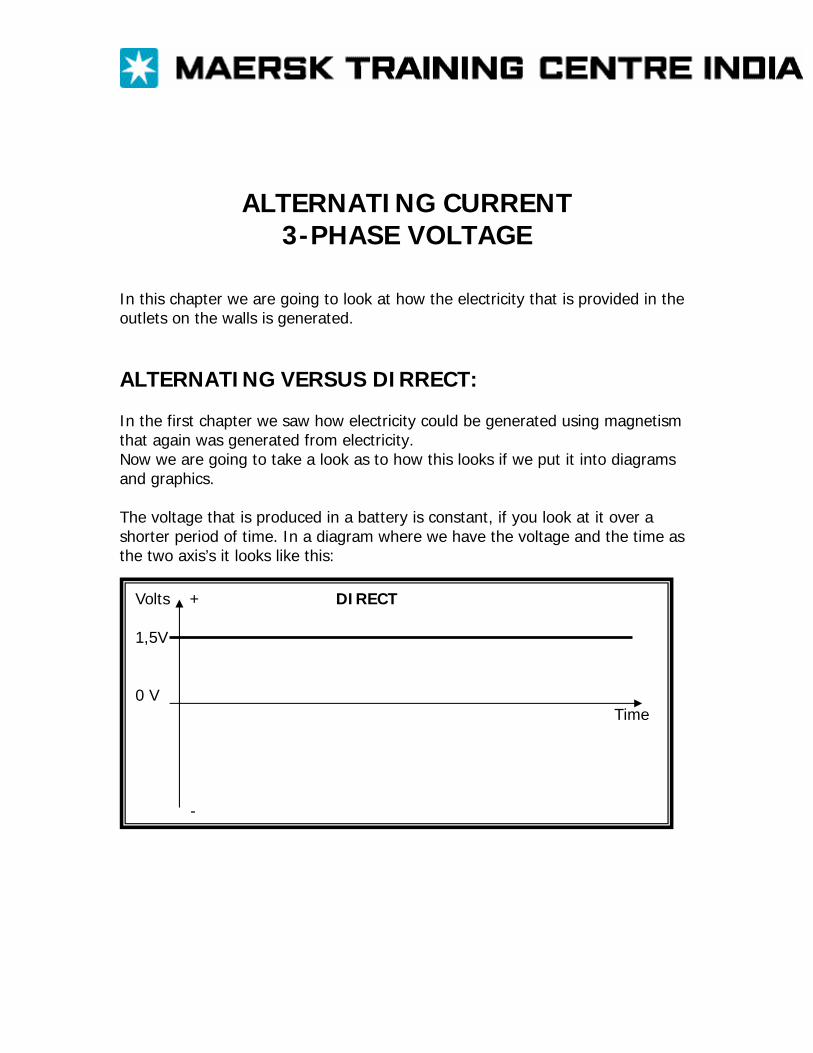
In this chapter we are going to look at how the electricity that is provided in the outlets on the walls is generated. ALTERNATING VERSUS DIRRECT: In the first chapter we saw how electricity could be generated using magnetism that again was generated from electricity. Now we are going to take a look as to how this looks if we put it into diagrams and graphics. The voltage that is produced in a battery is constant, if you look at it over a shorter period of time. In a diagram where we have the voltage and the time as the two axis’s it looks like this:
Volts + DIRECT 1,5V 0 V Time -
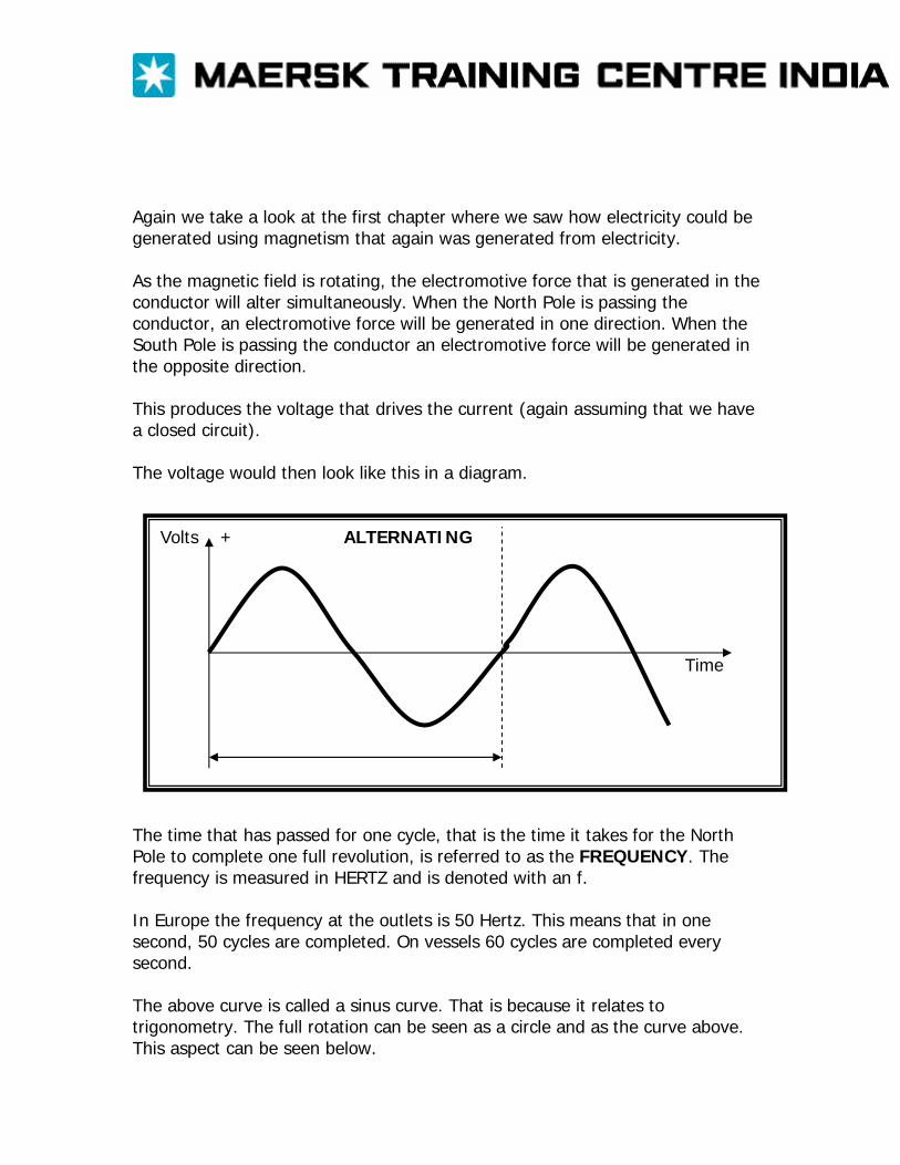
Again we take a look at the first chapter where we saw how electricity could be generated using magnetism that again was generated from electricity. As the magnetic field is rotating, the electromotive force that is generated in the conductor will alter simultaneously. When the North Pole is passing the conductor, an electromotive force will be generated in one direction. When the South Pole is passing the conductor an electromotive force will be generated in the opposite direction. This produces the voltage that drives the current (again assuming that we have a closed circuit). The voltage would then look like this in a diagram.
Volts + ALTERNATING Time
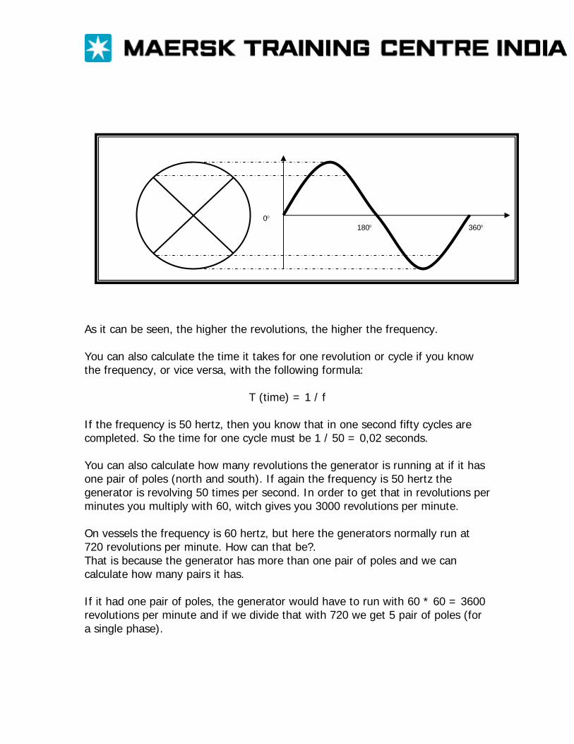
The time that has passed for one cycle, that is the time it takes for the North Pole to complete one full revolution, is referred to as the FREQUENCY. The frequency is measured in HERTZ and is denoted with an f. In Europe the frequency at the outlets is 50 Hertz. This means that in one second, 50 cycles are completed. On vessels 60 cycles are completed every second. The above curve is called a sinus curve. That is because it relates to trigonometry. The full rotation can be seen as a circle and as the curve above. This aspect can be seen below.
0° 180° 360°
As it can be seen, the higher the revolutions, the higher the frequency. You can also calculate the time it takes for one revolution or cycle if you know the frequency, or vice versa, with the following formula:
T (time) = 1 / f If the frequency is 50 hertz, then you know that in one second fifty cycles are completed. So the time for one cycle must be 1 / 50 = 0,02 seconds. You can also calculate how many revolutions the generator is running at if it has one pair of poles (north and south). If again the frequency is 50 hertz the generator is revolving 50 times per second. In order to get that in revolutions per minutes you multiply with 60, witch gives you 3000 revolutions per minute. On vessels the frequency is 60 hertz, but here the generators normally run at 720 revolutions per minute. How can that be?. That is because the generator has more than one pair of poles and we can calculate how many pairs it has. If it had one pair of poles, the generator would have to run with 60 * 60 = 3600 revolutions per minute and if we divide that with 720 we get 5 pair of poles (for a single phase).
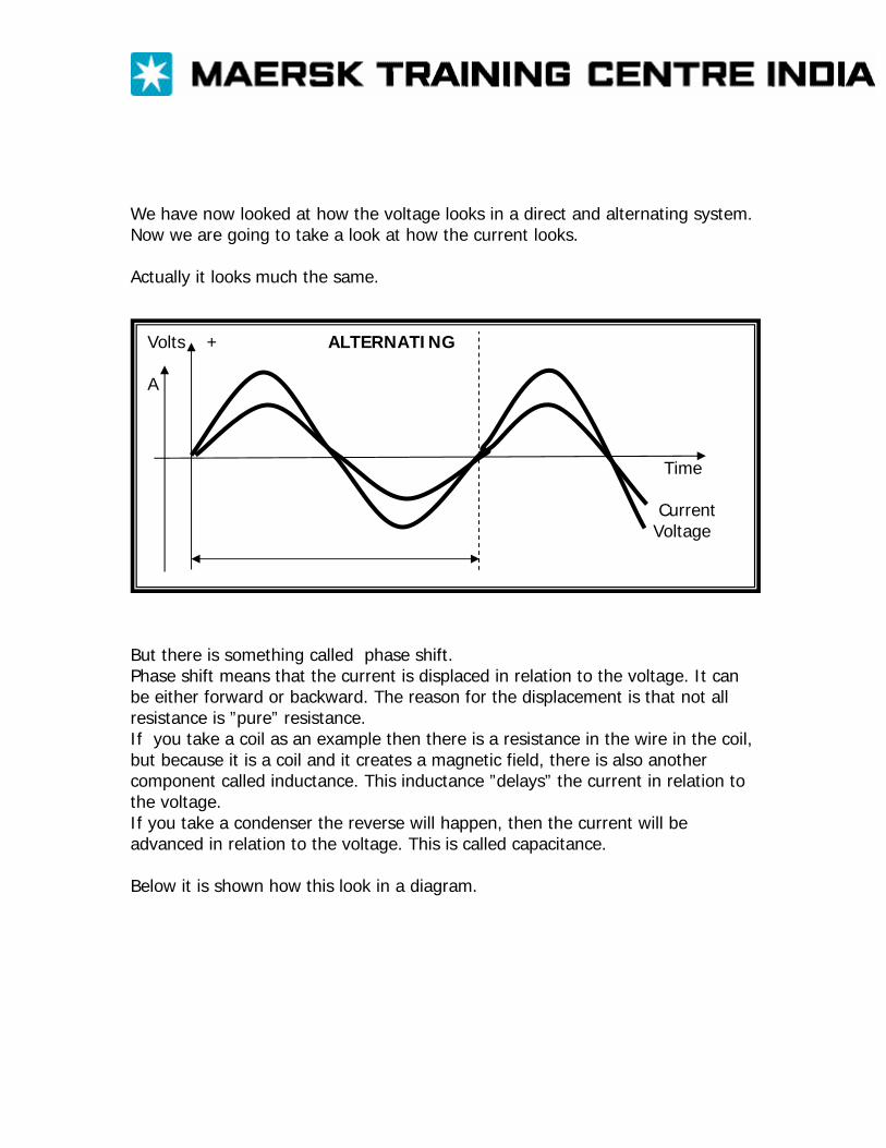
We have now looked at how the voltage looks in a direct and alternating system. Now we are going to take a look at how the current looks. Actually it looks much the same.
Volts + ALTERNATING A Time Current Voltage
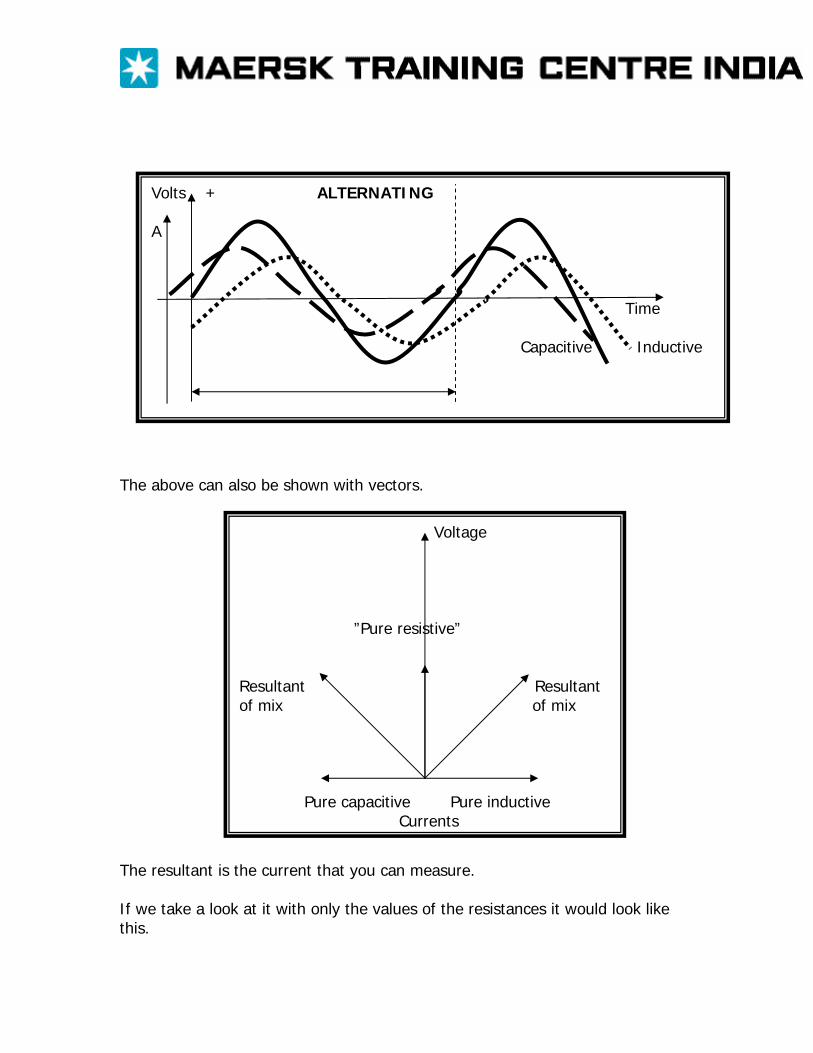
But there is something called phase shift. Phase shift means that the current is displaced in relation to the voltage. It can be either forward or backward. The reason for the displacement is that not all resistance is ”pure” resistance. If you take a coil as an example then there is a resistance in the wire in the coil, but because it is a coil and it creates a magnetic field, there is also another component called inductance. This inductance ”delays” the current in relation to the voltage. If you take a condenser the reverse will happen, then the current will be advanced in relation to the voltage. This is called capacitance. Below it is shown how this look in a diagram.
Volts + ALTERNATING A Time Capacitive Inductive
The above can also be shown with vectors.
Voltage ”Pure resistive” Resultant Resultant of mix of mix Pure capacitive Pure inductive Currents
The resultant is the current that you can measure. If we take a look at it with only the values of the resistances it would look like this.
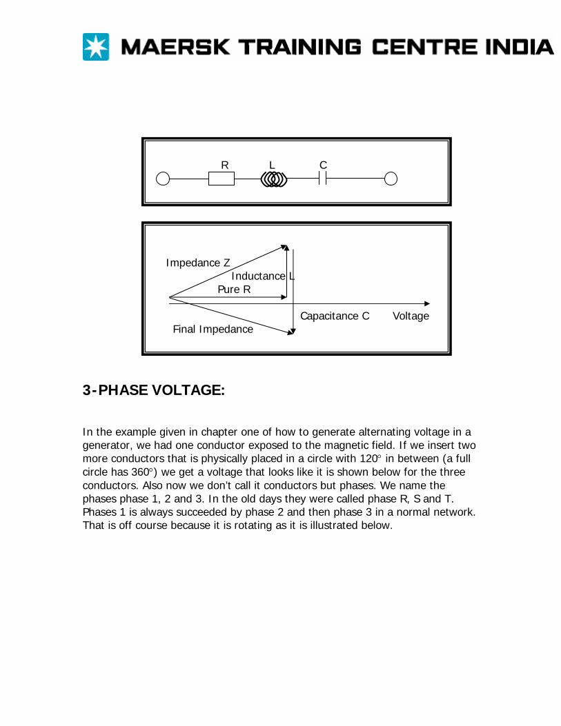
R L C
Impedance Z Inductance L Pure R Capacitance C Voltage Final Impedance
3-PHASE VOLTAGE: In the example given in chapter one of how to generate alternating voltage in a generator, we had one conductor exposed to the magnetic field. If we insert two more conductors that is physically placed in a circle with 120° in between (a full circle has 360°) we get a voltage that looks like it is shown below for the three conductors. Also now we don’t call it conductors but phases. We name the phases phase 1, 2 and 3. In the old days they were called phase R, S and T. Phases 1 is always succeeded by phase 2 and then phase 3 in a normal network. That is off course because it is rotating as it is illustrated below.
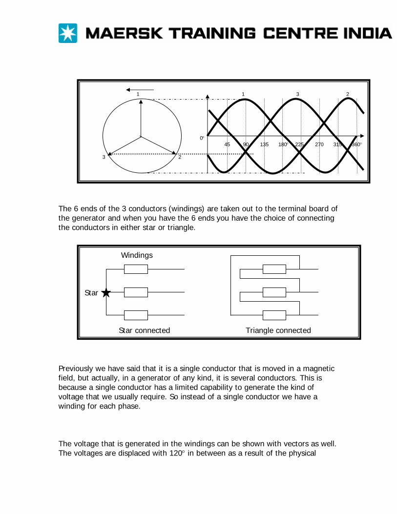
1 1 3 2 0° 45 90 135 180° 225 270 315 360° 3 2
The 6 ends of the 3 conductors (windings) are taken out to the terminal board of the generator and when you have the 6 ends you have the choice of connecting the conductors in either star or triangle.
Windings Star Star connected Triangle connected
Previously we have said that it is a single conductor that is moved in a magnetic field, but actually, in a generator of any kind, it is several conductors. This is because a single conductor has a limited capability to generate the kind of voltage that we usually require. So instead of a single conductor we have a winding for each phase. The voltage that is generated in the windings can be shown with vectors as well. The voltages are displaced with 120° in between as a result of the physical
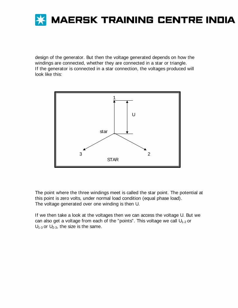
design of the generator. But then the voltage generated depends on how the windings are connected, whether they are connected in a star or triangle. If the generator is connected in a star connection, the voltages produced will look like this:
1 U star 3 2 STAR
The point where the three windings meet is called the star point. The potential at this point is zero volts, under normal load condition (equal phase load). The voltage generated over one winding is then U. If we then take a look at the voltages then we can access the voltage U. But we can also get a voltage from each of the ”points”. This voltage we call U1-2 or U1-3 or U2-3, the size is the same.
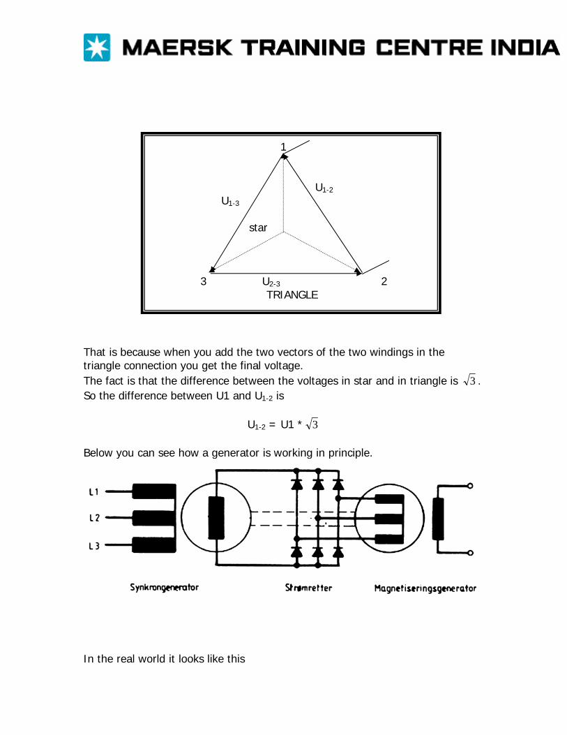
1 U1-2
U1-3
star 3 U2-3 2 TRIANGLE
That is because when you add the two vectors of the two windings in the triangle connection you get the final voltage. The fact is that the difference between the voltages in star and in triangle is 3 . So the difference between U1 and U1-2 is
U1-2 = U1 * 3
Below you can see how a generator is working in principle.
In the real world it looks like this
RECTIFIED VOLTAGE: It is possible to rectify an alternating voltage so you end up having what appears to be a direct voltage. It is done by means of connecting diodes in a certain way. A diode is a component that allows a current or voltage to have one direction only. You could say it works like a check valve, a one way valve. If you put a diode in a circuit with alternating voltage you will only get either the positive or negative part of the sinus curve through the diode. This off course depends on how you turn the diode in the circuit.
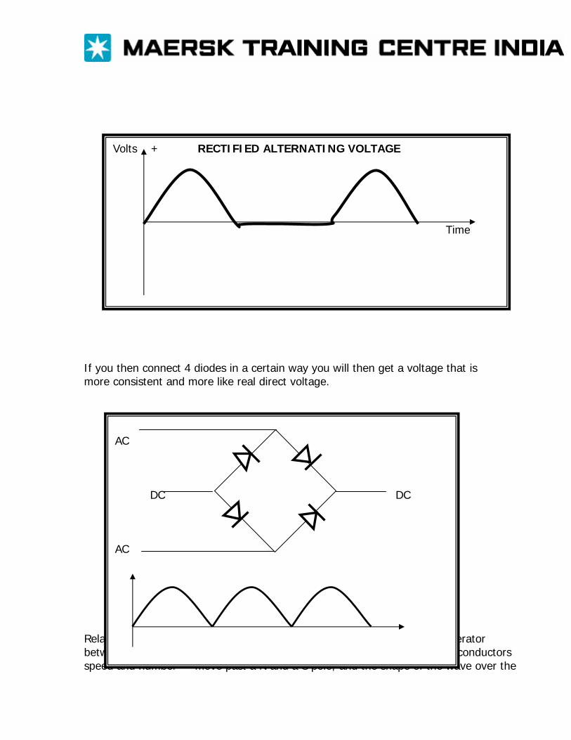
If you then connect 4 diodes in a certain way you will then get a voltage that is more consistent and more like real direct voltage. Relationship between frequency, speed and number
The waveform of the e.m.f. generated in an a.c. generator undergoes one complete cycle of variation when the conductors move past a N and a S pole; and the shape of the wave over the
Volts + RECTIFIED ALTERNATING VOLTAGE Time
AC DC DC AC
of pole pairs negative half is exactly the same as that over the positive half. This symmetry of the positive and negative half-cycles does not necessarily hold for waveform of voltage and current in circuits incorporating rectifiers or transistors. If an a.c. generator has p pairs of poles and if its speed is N revolutions per second, then Frequency = no. of cycles per second = no. of cycles per revolution x no of revolutions per second f= pN hertz
Average and r.m.s. values of an alternating current.
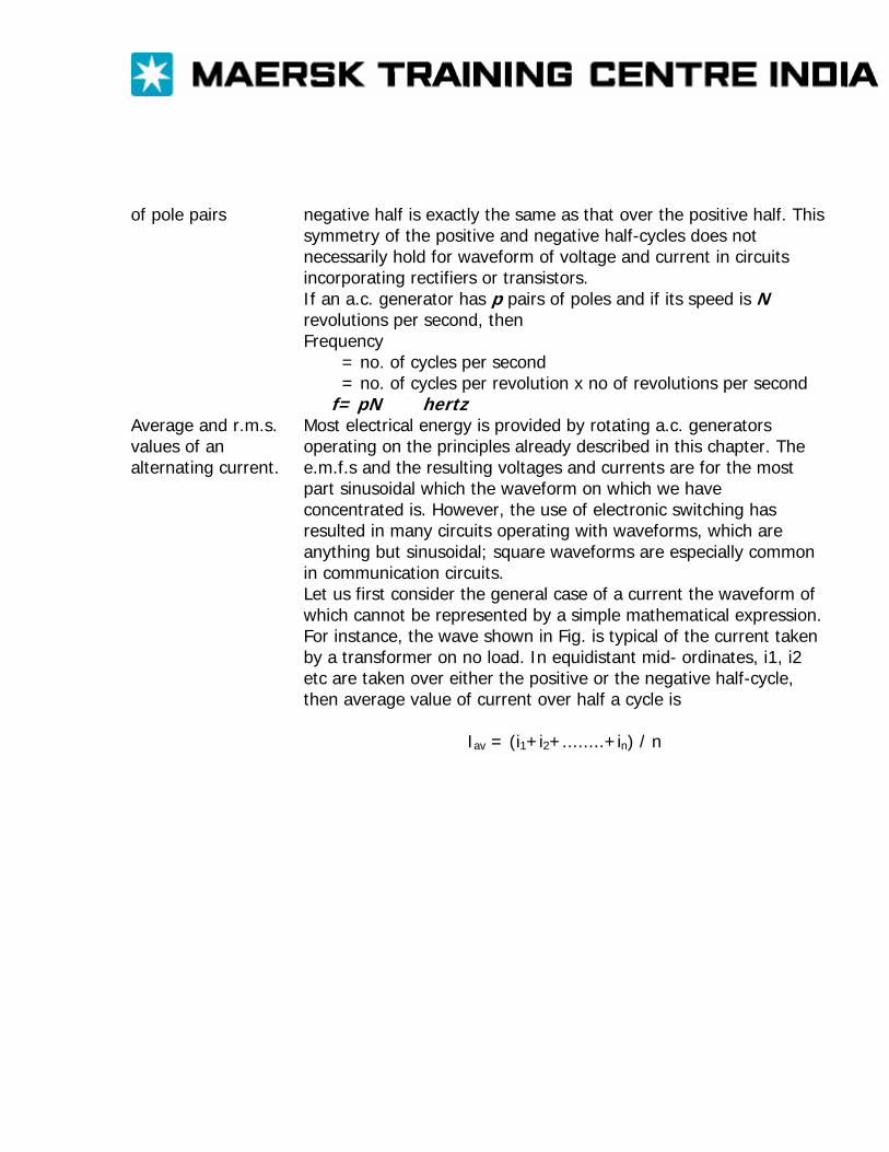
Most electrical energy is provided by rotating a.c. generators operating on the principles already described in this chapter. The e.m.f.s and the resulting voltages and currents are for the most part sinusoidal which the waveform on which we have concentrated is. However, the use of electronic switching has resulted in many circuits operating with waveforms, which are anything but sinusoidal; square waveforms are especially common in communication circuits. Let us first consider the general case of a current the waveform of which cannot be represented by a simple mathematical expression. For instance, the wave shown in Fig. is typical of the current taken by a transformer on no load. In equidistant mid- ordinates, i1, i2 etc are taken over either the positive or the negative half-cycle, then average value of current over half a cycle is Iav = (i1+i2+........+in) / n
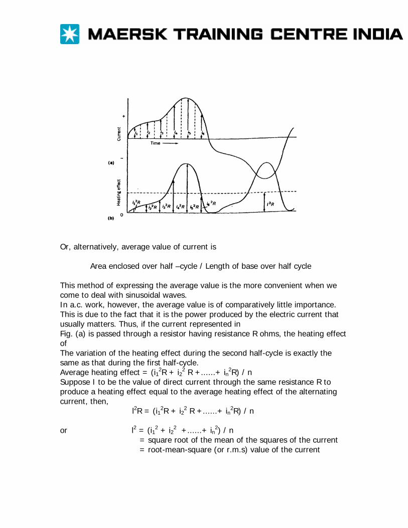
Or, alternatively, average value of current is Area enclosed over half –cycle / Length of base over half cycle This method of expressing the average value is the more convenient when we come to deal with sinusoidal waves. In a.c. work, however, the average value is of comparatively little importance. This is due to the fact that it is the power produced by the electric current that usually matters. Thus, if the current represented in Fig. (a) is passed through a resistor having resistance R ohms, the heating effect of The variation of the heating effect during the second half-cycle is exactly the same as that during the first half-cycle. Average heating effect = (i12R + i22 R +......+ in2R) / n Suppose I to be the value of direct current through the same resistance R to produce a heating effect equal to the average heating effect of the alternating current, then,
l2R = (i12R + i22 R +......+ in2R) / n or l2 = (i12 + i22 +......+ in2) / n
= square root of the mean of the squares of the current = root-mean-square (or r.m.s) value of the current
SUPPLY NETWORK You have now learned how electricity is generated, what the difference between AC and DC is, what inductance and capacitance is and how 3-phase voltage is generated. Now we are going to look at how the network that supplies the appliances and machines onshore and offshore looks like. ONSHORE NETWORK: The onshore network basically starts at the power plant and ends in the outlets at the consumer. There is a difference though, the voltage. The voltage at the outlets is 400/230 V, the voltage at the power plant is 400.000 V. So the voltage is transformed under way to the consumer. The reason for the transformation is that there is a resistance in the cables and thus a power loss. If you remember the power sentence it said P = U * I which could be rewritten to P = I2 * R. At the power plant there is a lot of power produced ( peak value for Denmark, consumption of 5.750.000.000 W ) and if it was produced at 400 volts then the current would have to be very large ( P = U * I ⇒ I = 14.375.000 A ). And when the current is very large a lot of power would be lost in the cables as heat is produced (P = I2 * R). Furthermore, because of the high current and the resistance there would also be a drop in the voltage that would be unacceptable. So we have a high voltage and a low current, thus a small power loss and a small drop in the voltage. And then we have to transform the voltages as we move on in the network as it can be seen below. For your information, a transformer works like a generator, only it is not rotating.
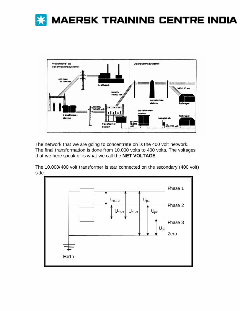
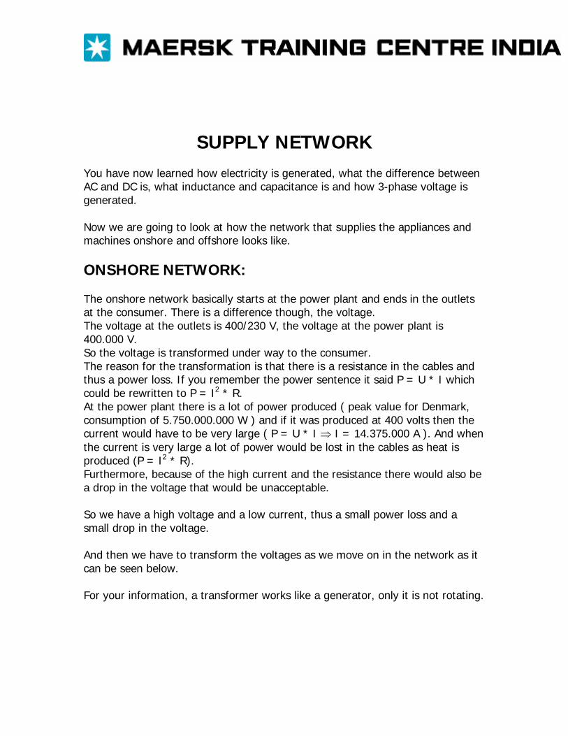
The network that we are going to concentrate on is the 400 volt network. The final transformation is done from 10.000 volts to 400 volts. The voltages that we here speak of is what we call the NET VOLTAGE. The 10.000/400 volt transformer is star connected on the secondary (400 volt) side.
Phase 1 Un1-2 Up1 Phase 2 Un2-3 Un1-3 Up2 Phase 3 Up3 Zero Earth
So the net voltage which is the voltage between two phases is 400 volts. We have also introduced another wire, the Zero wire. It is connected to the star point of the transformer. And under normal conditions the potential of the star point is ZERO volts, which is why we call the Zero wire zero. Furthermore the zero wire is grounded (connected to earth), so we are sure that we have 0 volts on the Zero wire. The voltage that we can measure between zero and a phase is called the PHASE VOLTAGE. The difference between the two voltages is 3 , as we saw in chapter 2. So if the net voltage is 400 volts then the phase voltage is
400 / 3 = 231 volts
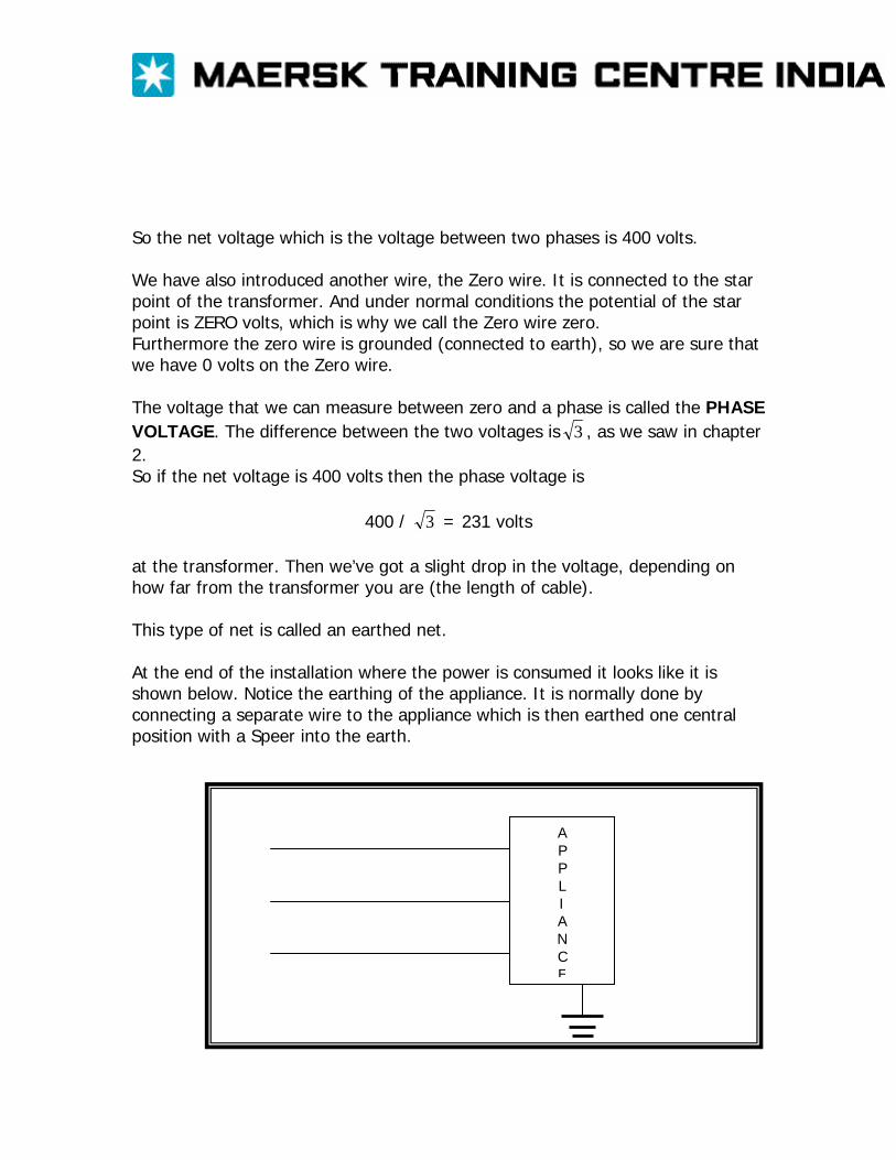
at the transformer. Then we’ve got a slight drop in the voltage, depending on how far from the transformer you are (the length of cable). This type of net is called an earthed net. At the end of the installation where the power is consumed it looks like it is shown below. Notice the earthing of the appliance. It is normally done by connecting a separate wire to the appliance which is then earthed one central position with a Speer into the earth.
A P P L I A N C E
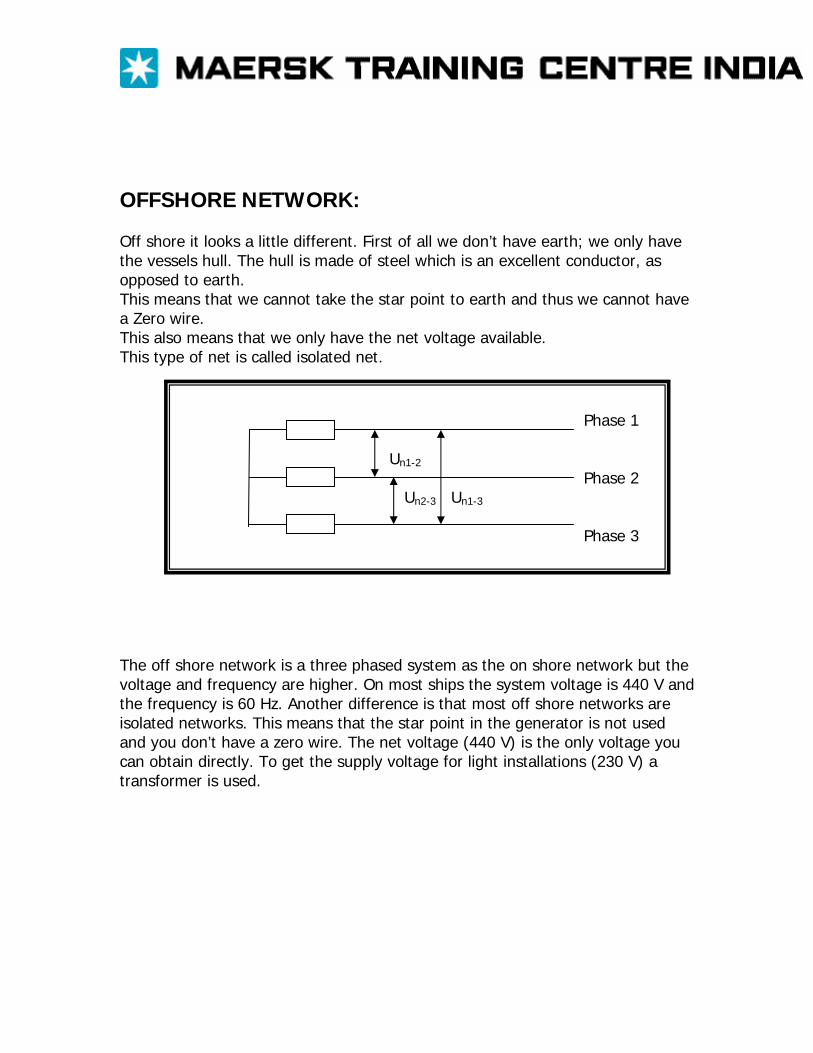
OFFSHORE NETWORK: Off shore it looks a little different. First of all we don’t have earth; we only have the vessels hull. The hull is made of steel which is an excellent conductor, as opposed to earth. This means that we cannot take the star point to earth and thus we cannot have a Zero wire. This also means that we only have the net voltage available. This type of net is called isolated net.
Phase 1 Un1-2 Phase 2 Un2-3 Un1-3 Phase 3
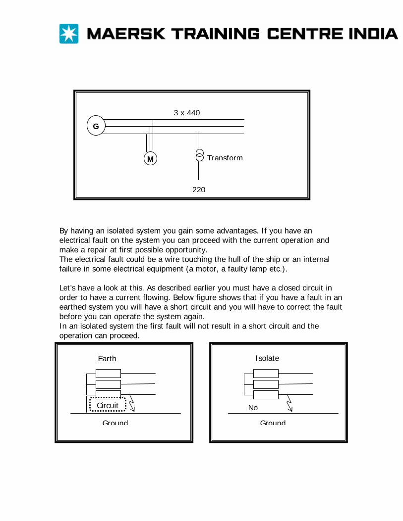
The off shore network is a three phased system as the on shore network but the voltage and frequency are higher. On most ships the system voltage is 440 V and the frequency is 60 Hz. Another difference is that most off shore networks are isolated networks. This means that the star point in the generator is not used and you don’t have a zero wire. The net voltage (440 V) is the only voltage you can obtain directly. To get the supply voltage for light installations (230 V) a transformer is used.
Transform
220
3 x 440
G
M
By having an isolated system you gain some advantages. If you have an electrical fault on the system you can proceed with the current operation and make a repair at first possible opportunity. The electrical fault could be a wire touching the hull of the ship or an internal failure in some electrical equipment (a motor, a faulty lamp etc.). Let’s have a look at this. As described earlier you must have a closed circuit in order to have a current flowing. Below figure shows that if you have a fault in an earthed system you will have a short circuit and you will have to correct the fault before you can operate the system again. In an isolated system the first fault will not result in a short circuit and the operation can proceed.
Earth
Circuit
Ground
Isolate
No
Ground
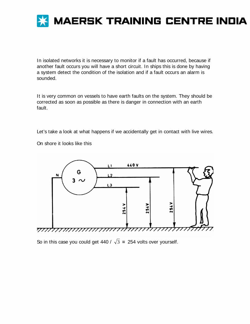
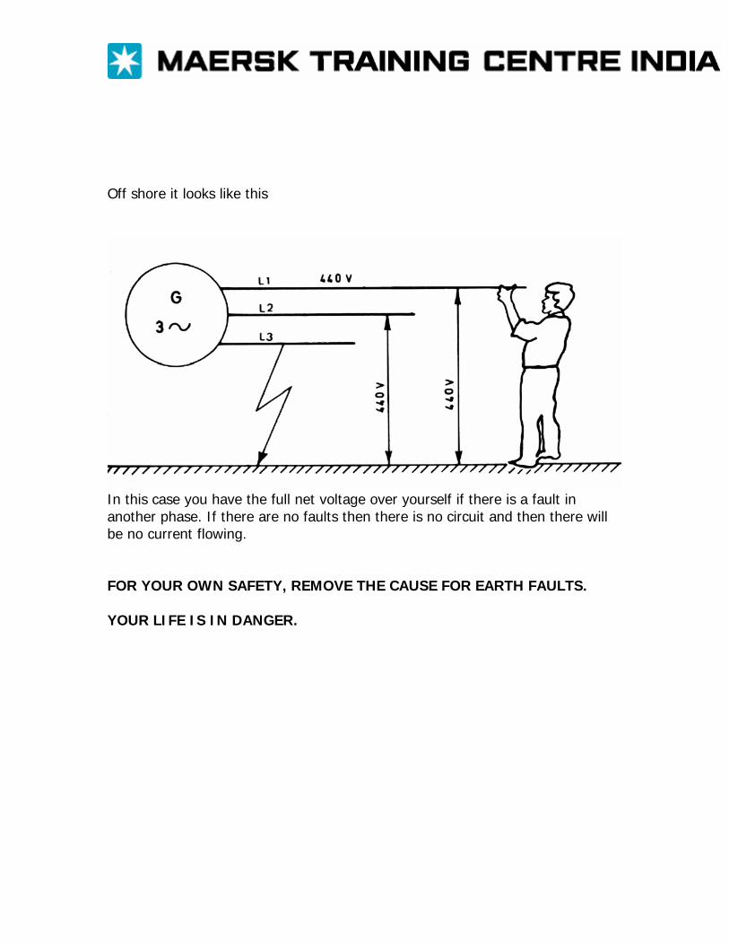
In isolated networks it is necessary to monitor if a fault has occurred, because if another fault occurs you will have a short circuit. In ships this is done by having a system detect the condition of the isolation and if a fault occurs an alarm is sounded. It is very common on vessels to have earth faults on the system. They should be corrected as soon as possible as there is danger in connection with an earth fault. Let’s take a look at what happens if we accidentally get in contact with live wires. On shore it looks like this
So in this case you could get 440 / 3 = 254 volts over yourself.
Off shore it looks like this
In this case you have the full net voltage over yourself if there is a fault in another phase. If there are no faults then there is no circuit and then there will be no current flowing. FOR YOUR OWN SAFETY, REMOVE THE CAUSE FOR EARTH FAULTS. YOUR LIFE IS IN DANGER.
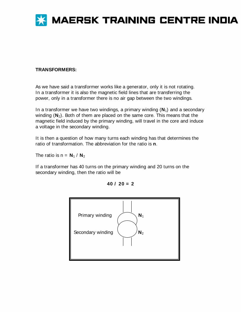
TRANSFORMERS: As we have said a transformer works like a generator, only it is not rotating. In a transformer it is also the magnetic field lines that are transferring the power, only in a transformer there is no air gap between the two windings. In a transformer we have two windings, a primary winding (N1) and a secondary winding (N2). Both of them are placed on the same core. This means that the magnetic field induced by the primary winding, will travel in the core and induce a voltage in the secondary winding. It is then a question of how many turns each winding has that determines the ratio of transformation. The abbreviation for the ratio is n. The ratio is n = N1 / N2
If a transformer has 40 turns on the primary winding and 20 turns on the secondary winding, then the ratio will be
40 / 20 = 2
Primary winding N1
Secondary winding N2

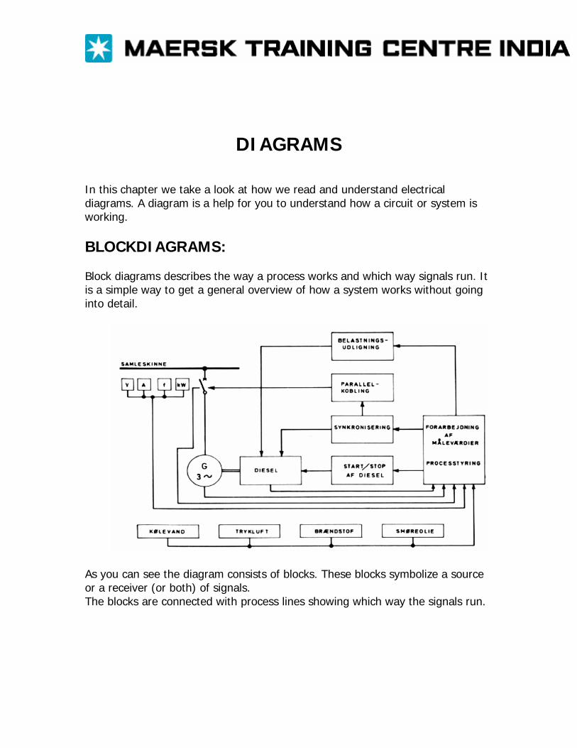
DIAGRAMS In this chapter we take a look at how we read and understand electrical diagrams. A diagram is a help for you to understand how a circuit or system is working. BLOCKDIAGRAMS: Block diagrams describes the way a process works and which way signals run. It is a simple way to get a general overview of how a system works without going into detail.
As you can see the diagram consists of blocks. These blocks symbolize a source or a receiver (or both) of signals. The blocks are connected with process lines showing which way the signals run.
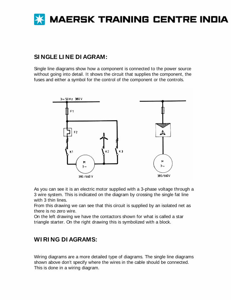
SINGLE LINE DIAGRAM: Single line diagrams show how a component is connected to the power source without going into detail. It shows the circuit that supplies the component, the fuses and either a symbol for the control of the component or the controls.
As you can see it is an electric motor supplied with a 3-phase voltage through a 3 wire system. This is indicated on the diagram by crossing the single fat line with 3 thin lines. From this drawing we can see that this circuit is supplied by an isolated net as there is no zero wire. On the left drawing we have the contactors shown for what is called a star triangle starter. On the right drawing this is symbolized with a block. WIRING DIAGRAMS: Wiring diagrams are a more detailed type of diagrams. The single line diagrams shown above don’t specify where the wires in the cable should be connected. This is done in a wiring diagram.
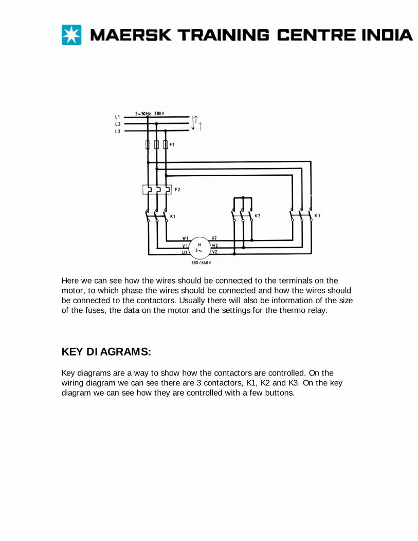
Here we can see how the wires should be connected to the terminals on the motor, to which phase the wires should be connected and how the wires should be connected to the contactors. Usually there will also be information of the size of the fuses, the data on the motor and the settings for the thermo relay. KEY DIAGRAMS: Key diagrams are a way to show how the contactors are controlled. On the wiring diagram we can see there are 3 contactors, K1, K2 and K3. On the key diagram we can see how they are controlled with a few buttons.
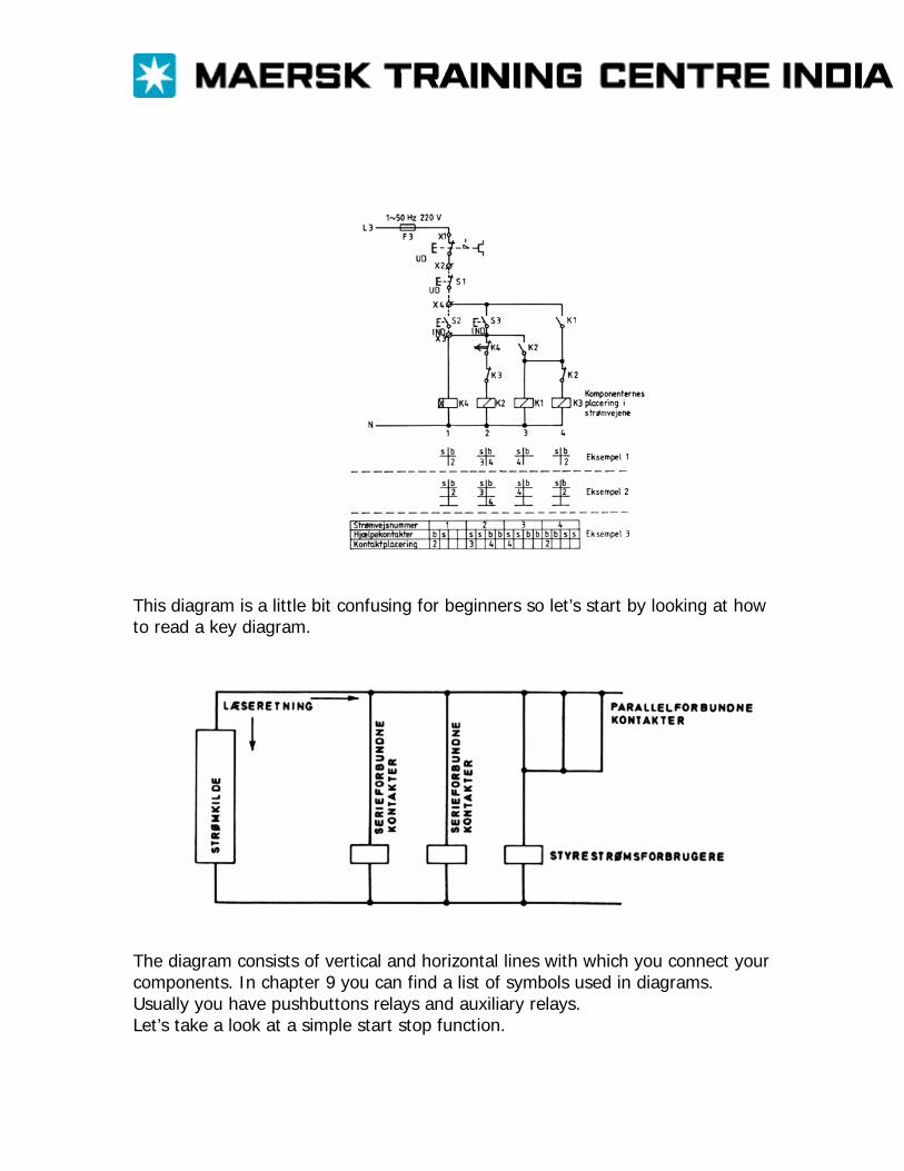
This diagram is a little bit confusing for beginners so let’s start by looking at how to read a key diagram.
The diagram consists of vertical and horizontal lines with which you connect your components. In chapter 9 you can find a list of symbols used in diagrams. Usually you have pushbuttons relays and auxiliary relays. Let’s take a look at a simple start stop function.
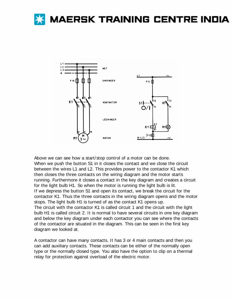
Above we can see how a start/stop control of a motor can be done. When we push the button S1 in it closes the contact and we close the circuit between the wires L1 and L2. This provides power to the contactor K1 which then closes the three contacts on the wiring diagram and the motor starts running. Furthermore it closes a contact in the key diagram and creates a circuit for the light bulb H1. So when the motor is running the light bulb is lit. If we depress the button S1 and open its contact, we break the circuit for the contactor K1. Thus the three contacts in the wiring diagram opens and the motor stops. The light bulb H1 is turned of as the contact K1 opens up. The circuit with the contactor K1 is called circuit 1 and the circuit with the light bulb H1 is called circuit 2. It is normal to have several circuits in one key diagram and below the key diagram under each contactor you can see where the contacts of the contactor are situated in the diagram. This can be seen in the first key diagram we looked at. A contactor can have many contacts. It has 3 or 4 main contacts and then you can add auxiliary contacts. These contacts can be either of the normally open type or the normally closed type. You also have the option to clip on a thermal relay for protection against overload of the electric motor.
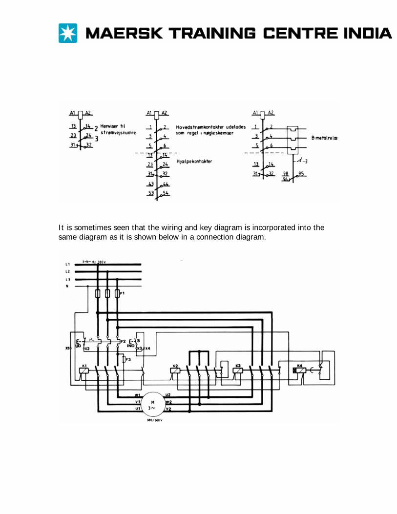
It is sometimes seen that the wiring and key diagram is incorporated into the same diagram as it is shown below in a connection diagram.
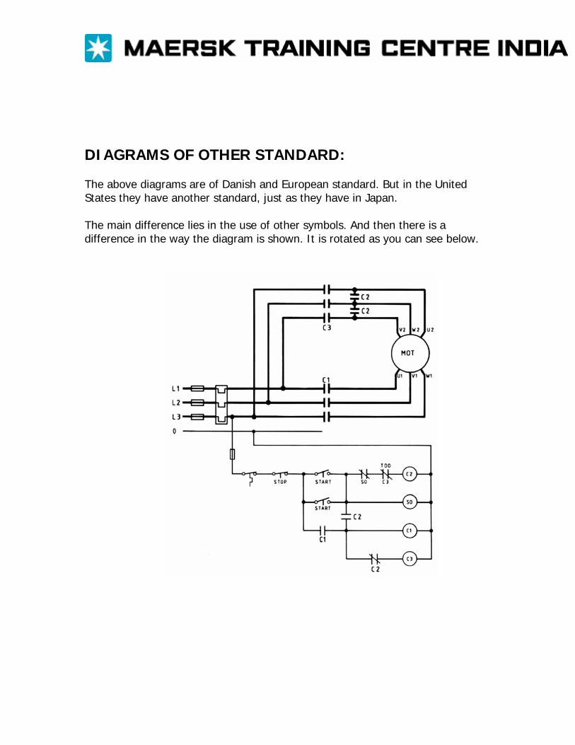
DIAGRAMS OF OTHER STANDARD: The above diagrams are of Danish and European standard. But in the United States they have another standard, just as they have in Japan. The main difference lies in the use of other symbols. And then there is a difference in the way the diagram is shown. It is rotated as you can see below.
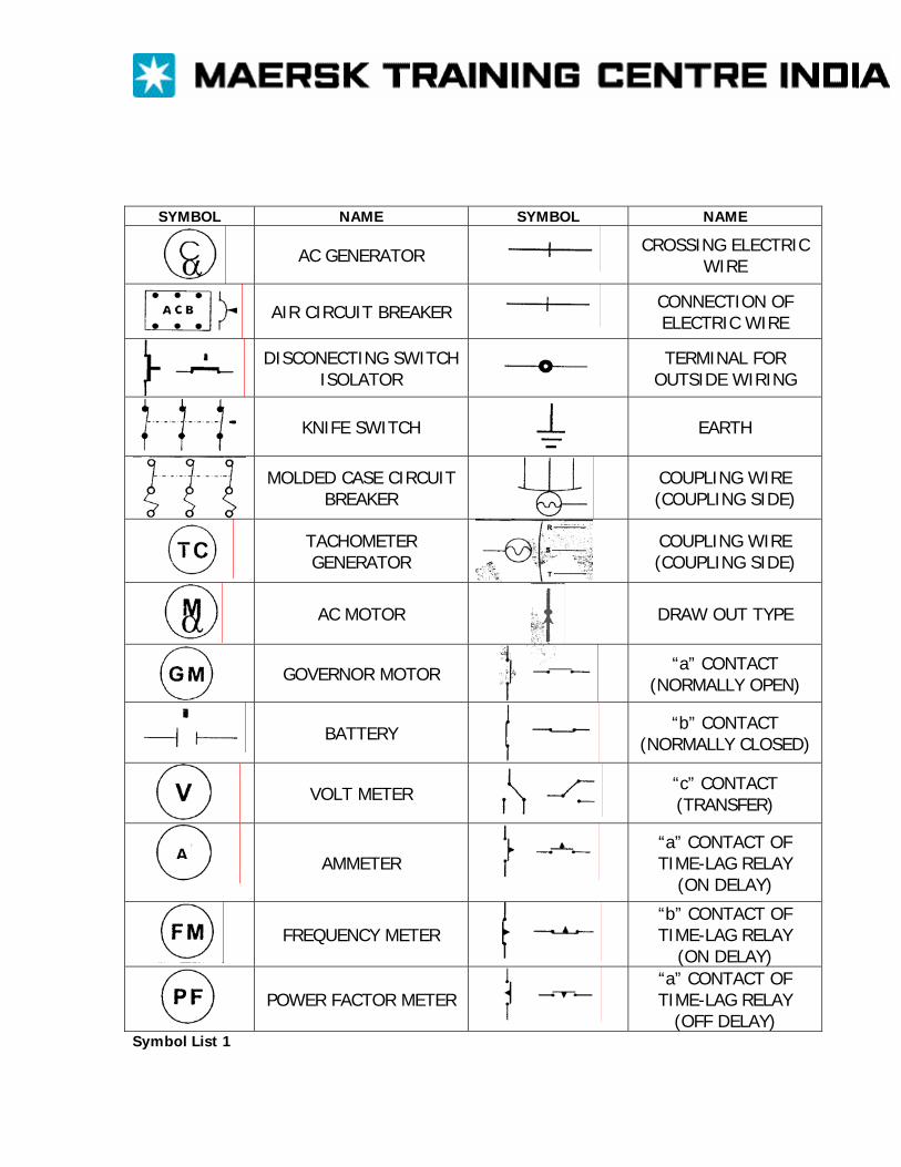
SYMBOL NAME SYMBOL NAME
AC GENERATOR
CROSSING ELECTRIC WIRE
AIR CIRCUIT BREAKER
CONNECTION OF ELECTRIC WIRE
DISCONECTING SWITCH ISOLATOR
TERMINAL FOR OUTSIDE WIRING
KNIFE SWITCH
EARTH
MOLDED CASE CIRCUIT BREAKER
COUPLING WIRE (COUPLING SIDE)
TACHOMETER GENERATOR
COUPLING WIRE (COUPLING SIDE)
AC MOTOR
DRAW OUT TYPE
GOVERNOR MOTOR
“a” CONTACT (NORMALLY OPEN)
BATTERY
“b” CONTACT (NORMALLY CLOSED)
VOLT METER
“c” CONTACT (TRANSFER)
AMMETER
“a” CONTACT OF TIME-LAG RELAY
(ON DELAY)
FREQUENCY METER
“b” CONTACT OF TIME-LAG RELAY
(ON DELAY)
POWER FACTOR METER
“a” CONTACT OF TIME-LAG RELAY
(OFF DELAY)
A
Symbol List 1
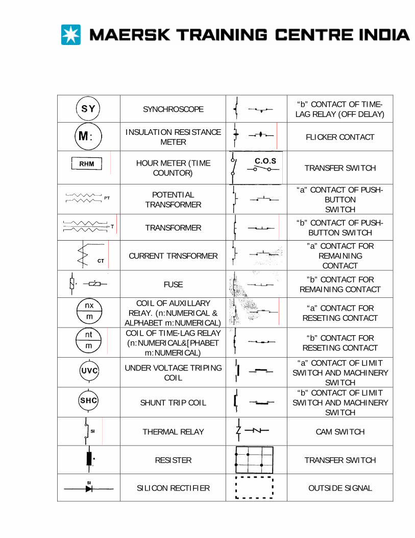
SYNCHROSCOPE
“b” CONTACT OF TIME-LAG RELAY (OFF DELAY)
INSULATION RESISTANCE METER
FLICKER CONTACT
HOUR METER (TIME
COUNTOR) TRANSFER SWITCH
POTENTIAL
TRANSFORMER
“a” CONTACT OF PUSH-BUTTON SWITCH
TRANSFORMER
“b” CONTACT OF PUSH-BUTTON SWITCH
CURRENT TRNSFORMER
”a” CONTACT FOR REMAINING CONTACT
FUSE
”b” CONTACT FOR REMAINING CONTACT
COIL OF AUXILLARY REtAY. (n:NUMERICAL &
ALPHABET m:NUMERICAL)
“a” CONTACT FOR RESETING CONTACT
COIL OF TIME-LAG RELAY (n:NUMERICAL&[PHABET
m:NUMERICAL)
“b” CONTACT FOR RESETING CONTACT
UNDER VOLTAGE TRIPING COIL
“a” CONTACT OF LIMIT SWITCH AND MACHINERY
SWITCH
SHUNT TRIP COIL
“b” CONTACT OF LIMIT SWITCH AND MACHINERY
SWITCH
THERMAL RELAY
CAM SWITCH
RESISTER
TRANSFER SWITCH
SILICON RECTIFIER
OUTSIDE SIGNAL
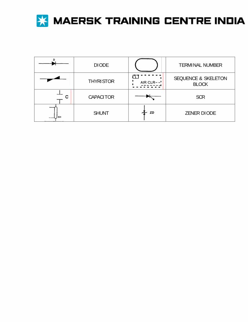
DIODE
TERMINAL NUMBER
THYRISTOR SEQUENCE & SKELETON
BLOCK
CAPACITOR
SCR
SHUNT
ZENER DIODE
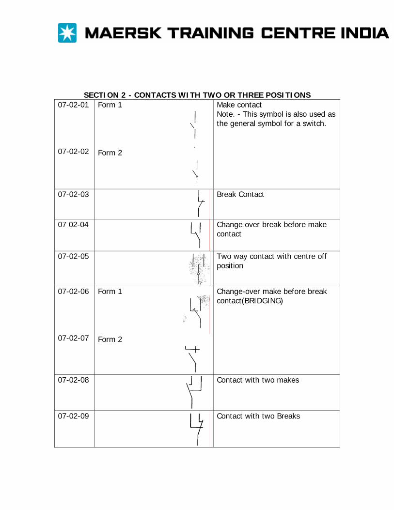
SECTION 2 - CONTACTS WITH TWO OR THREE POSITIONS 07-02-01 07-02-02
Form 1
Form 2
Make contact Note. - This symbol is also used as the general symbol for a switch.
07-02-03 Break Contact
07 02-04 Change over break before make contact
07-02-05 Two way contact with centre off position
07-02-06 07-02-07
Form 1
Form 2
Change-over make before break contact(BRIDGING)
07-02-08 Contact with two makes
07-02-09 Contact with two Breaks
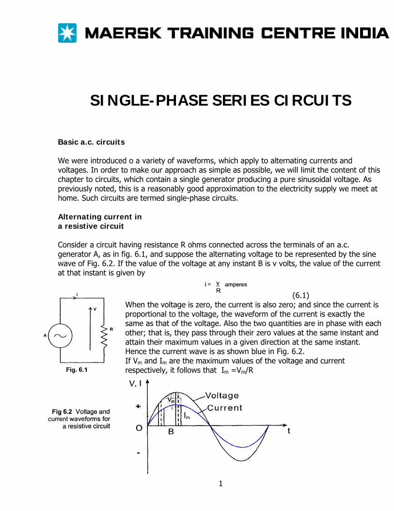
SINGLE-PHASE SERIES CIRCUITS Basic a.c. circuits We were introduced o a variety of waveforms, which apply to alternating currents and voltages. In order to make our approach as simple as possible, we will limit the content of this chapter to circuits, which contain a single generator producing a pure sinusoidal voltage. As previously noted, this is a reasonably good approximation to the electricity supply we meet at home. Such circuits are termed single-phase circuits. Alternating current in a resistive circuit Consider a circuit having resistance R ohms connected across the terminals of an a.c. generator A, as in fig. 6.1, and suppose the alternating voltage to be represented by the sine wave of Fig. 6.2. If the value of the voltage at any instant B is v volts, the value of the current at that instant is given by
(6.1) When the voltage is zero, the current is also zero; and since the current is proportional to the voltage, the waveform of the current is exactly the same as that of the voltage. Also the two quantities are in phase with each other; that is, they pass through their zero values at the same instant and attain their maximum values in a given direction at the same instant. Hence the current wave is as shown blue in Fig. 6.2. If Vm and Im are the maximum values of the voltage and current respectively, it follows that Im =Vm/R
1
But the r.m.s. value of a sine wave is 0.707 times the maximum value, so that r.m.s. value of voltage = V = 0.707 Vm and r.m.s. value of current = V = 0.707 Im
Substituting for Im and Vm in equation [6.1] we have I/0.707 = V/.707R I = V/R [6.2] Hence Ohm’s law can be applied without any modification to an a.c. circuit possessing resistance only. If the instantaneous value of the applied voltage is represented by V Vm sin wt, then instantaneous value of current in a resistive circuit is I = V/R sin wt [6.3]
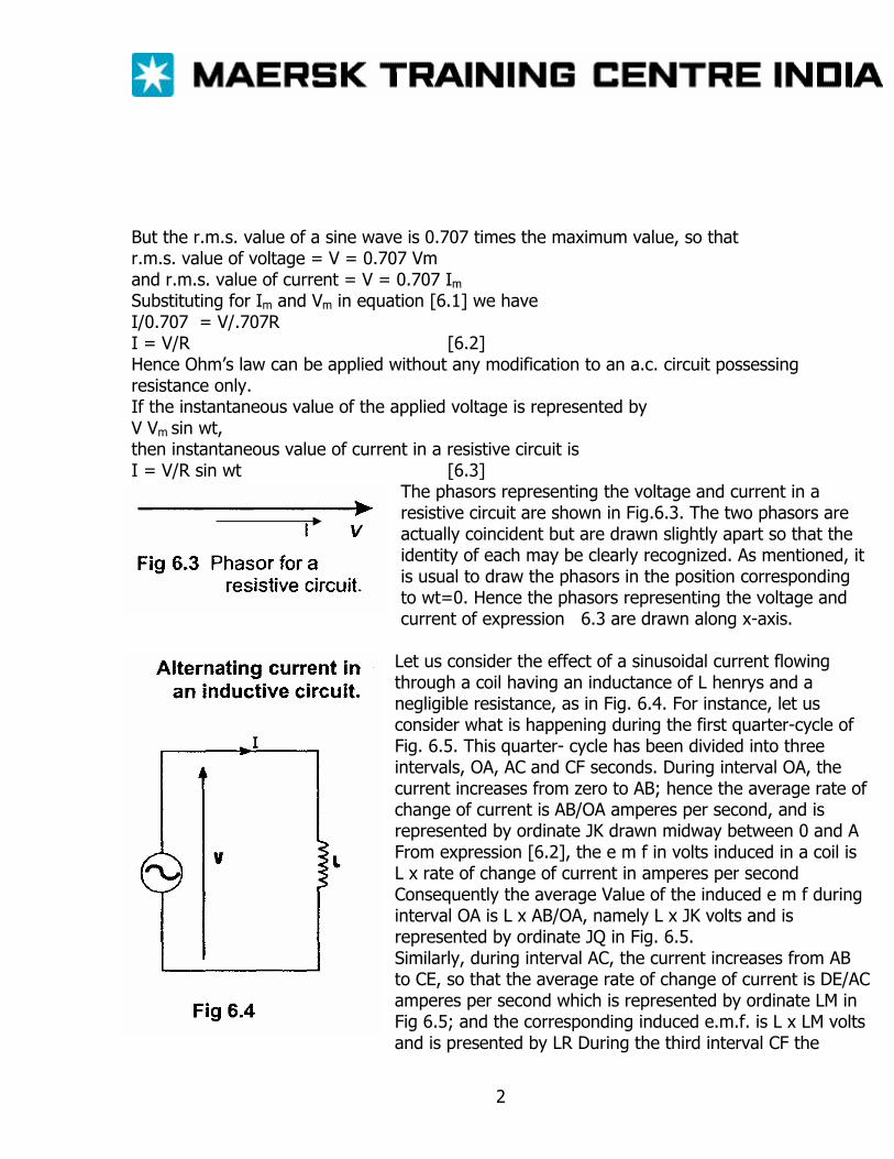
The phasors representing the voltage and current in a resistive circuit are shown in Fig.6.3. The two phasors are actually coincident but are drawn slightly apart so that the identity of each may be clearly recognized. As mentioned, it is usual to draw the phasors in the position corresponding to wt=0. Hence the phasors representing the voltage and current of expression 6.3 are drawn along x-axis.
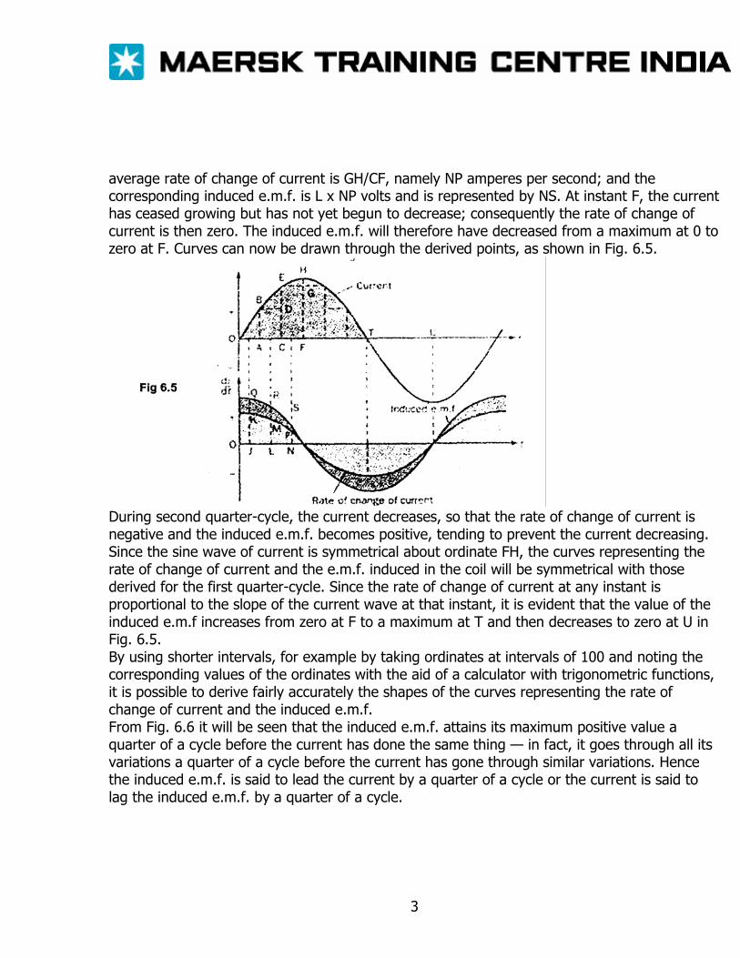
Let us consider the effect of a sinusoidal current flowing through a coil having an inductance of L henrys and a negligible resistance, as in Fig. 6.4. For instance, let us consider what is happening during the first quarter-cycle of Fig. 6.5. This quarter- cycle has been divided into three intervals, OA, AC and CF seconds. During interval OA, the current increases from zero to AB; hence the average rate of change of current is AB/OA amperes per second, and is represented by ordinate JK drawn midway between 0 and A From expression [6.2], the e m f in volts induced in a coil is L x rate of change of current in amperes per second Consequently the average Value of the induced e m f during interval OA is L x AB/OA, namely L x JK volts and is represented by ordinate JQ in Fig. 6.5. Similarly, during interval AC, the current increases from AB to CE, so that the average rate of change of current is DE/AC amperes per second which is represented by ordinate LM in Fig 6.5; and the corresponding induced e.m.f. is L x LM volts and is presented by LR During the third interval CF the
2
average rate of change of current is GH/CF, namely NP amperes per second; and the corresponding induced e.m.f. is L x NP volts and is represented by NS. At instant F, the current has ceased growing but has not yet begun to decrease; consequently the rate of change of current is then zero. The induced e.m.f. will therefore have decreased from a maximum at 0 to zero at F. Curves can now be drawn through the derived points, as shown in Fig. 6.5.
During second quarter-cycle, the current decreases, so that the rate of change of current is negative and the induced e.m.f. becomes positive, tending to prevent the current decreasing. Since the sine wave of current is symmetrical about ordinate FH, the curves representing the rate of change of current and the e.m.f. induced in the coil will be symmetrical with those derived for the first quarter-cycle. Since the rate of change of current at any instant is proportional to the slope of the current wave at that instant, it is evident that the value of the induced e.m.f increases from zero at F to a maximum at T and then decreases to zero at U in Fig. 6.5. By using shorter intervals, for example by taking ordinates at intervals of 100 and noting the corresponding values of the ordinates with the aid of a calculator with trigonometric functions, it is possible to derive fairly accurately the shapes of the curves representing the rate of change of current and the induced e.m.f. From Fig. 6.6 it will be seen that the induced e.m.f. attains its maximum positive value a quarter of a cycle before the current has done the same thing — in fact, it goes through all its variations a quarter of a cycle before the current has gone through similar variations. Hence the induced e.m.f. is said to lead the current by a quarter of a cycle or the current is said to lag the induced e.m.f. by a quarter of a cycle.
3
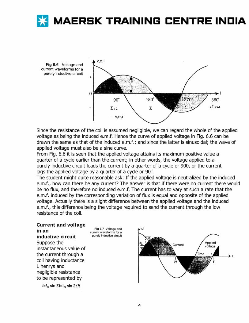
Since the resistance of the coil is assumed negligible, we can regard the whole of the applied voltage as being the induced e.m.f. Hence the curve of applied voltage in Fig. 6.6 can be drawn the same as that of the induced e.m.f.; and since the latter is sinusoidal; the wave of applied voltage must also be a sine curve. From Fig. 6.6 it is seen that the applied voltage attains its maximum positive value a quarter of a cycle earlier than the current; in other words, the voltage applied to a purely inductive circuit leads the current by a quarter of a cycle or 900, or the current lags the applied voltage by a quarter of a cycle or 900. The student might quite reasonable ask: If the applied voltage is neutralized by the induced e.m.f., how can there be any current? The answer is that if there were no current there would be no flux, and therefore no induced e.m.f. The current has to vary at such a rate that the e.m.f. induced by the corresponding variation of flux is equal and opposite of the applied voltage. Actually there is a slight difference between the applied voltage and the induced e.m.f., this difference being the voltage required to send the current through the low resistance of the coil. Current and voltage in an inductive circuit Suppose the instantaneous value of the current through a coil having inductance L henrys and negligible resistance to be represented by
4
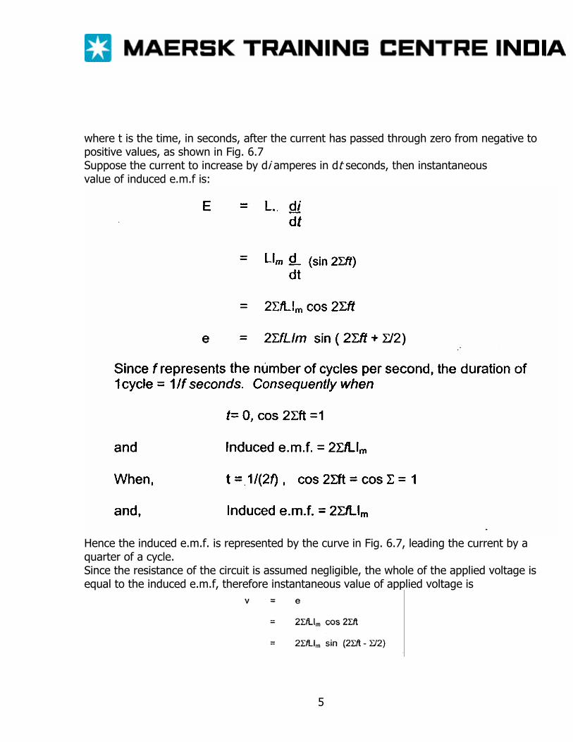
where t is the time, in seconds, after the current has passed through zero from negative to positive values, as shown in Fig. 6.7 Suppose the current to increase by di amperes in dt seconds, then instantaneous value of induced e.m.f is:
Hence the induced e.m.f. is represented by the curve in Fig. 6.7, leading the current by a quarter of a cycle. Since the resistance of the circuit is assumed negligible, the whole of the applied voltage is equal to the induced e.m.f, therefore instantaneous value of applied voltage is
5
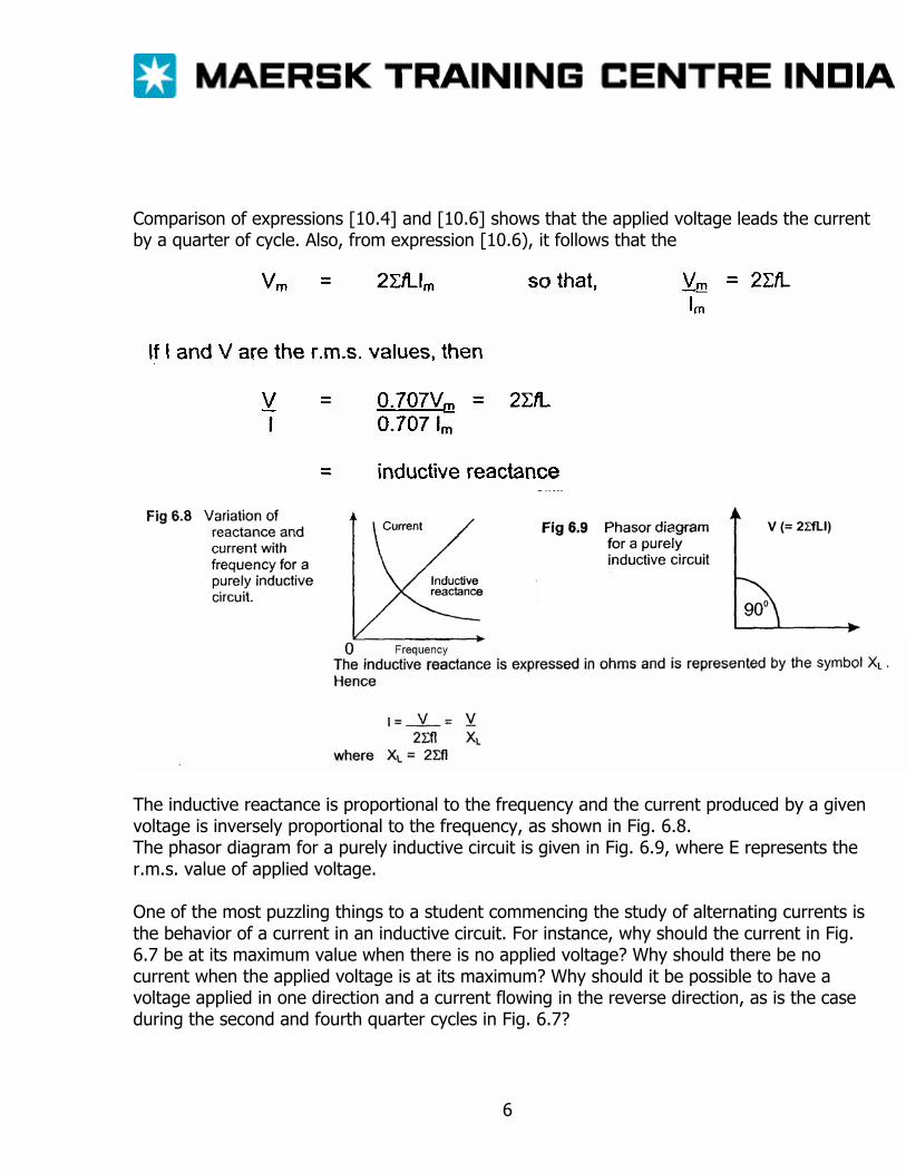
Comparison of expressions [10.4] and [10.6] shows that the applied voltage leads the current by a quarter of cycle. Also, from expression [10.6), it follows that the
The inductive reactance is proportional to the frequency and the current produced by a given voltage is inversely proportional to the frequency, as shown in Fig. 6.8. The phasor diagram for a purely inductive circuit is given in Fig. 6.9, where E represents the r.m.s. value of applied voltage. One of the most puzzling things to a student commencing the study of alternating currents is the behavior of a current in an inductive circuit. For instance, why should the current in Fig. 6.7 be at its maximum value when there is no applied voltage? Why should there be no current when the applied voltage is at its maximum? Why should it be possible to have a voltage applied in one direction and a current flowing in the reverse direction, as is the case during the second and fourth quarter cycles in Fig. 6.7?
6
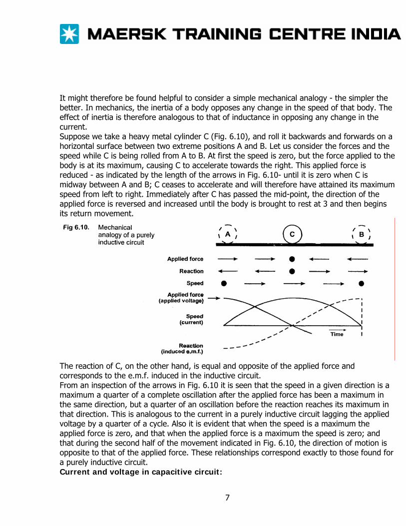
It might therefore be found helpful to consider a simple mechanical analogy - the simpler the better. In mechanics, the inertia of a body opposes any change in the speed of that body. The effect of inertia is therefore analogous to that of inductance in opposing any change in the current. Suppose we take a heavy metal cylinder C (Fig. 6.10), and roll it backwards and forwards on a horizontal surface between two extreme positions A and B. Let us consider the forces and the speed while C is being rolled from A to B. At first the speed is zero, but the force applied to the body is at its maximum, causing C to accelerate towards the right. This applied force is reduced - as indicated by the length of the arrows in Fig. 6.10- until it is zero when C is midway between A and B; C ceases to accelerate and will therefore have attained its maximum speed from left to right. Immediately after C has passed the mid-point, the direction of the applied force is reversed and increased until the body is brought to rest at 3 and then begins its return movement.
The reaction of C, on the other hand, is equal and opposite of the applied force and corresponds to the e.m.f. induced in the inductive circuit. From an inspection of the arrows in Fig. 6.10 it is seen that the speed in a given direction is a maximum a quarter of a complete oscillation after the applied force has been a maximum in the same direction, but a quarter of an oscillation before the reaction reaches its maximum in that direction. This is analogous to the current in a purely inductive circuit lagging the applied voltage by a quarter of a cycle. Also it is evident that when the speed is a maximum the applied force is zero, and that when the applied force is a maximum the speed is zero; and that during the second half of the movement indicated in Fig. 6.10, the direction of motion is opposite to that of the applied force. These relationships correspond exactly to those found for a purely inductive circuit. Current and voltage in capacitive circuit:
7
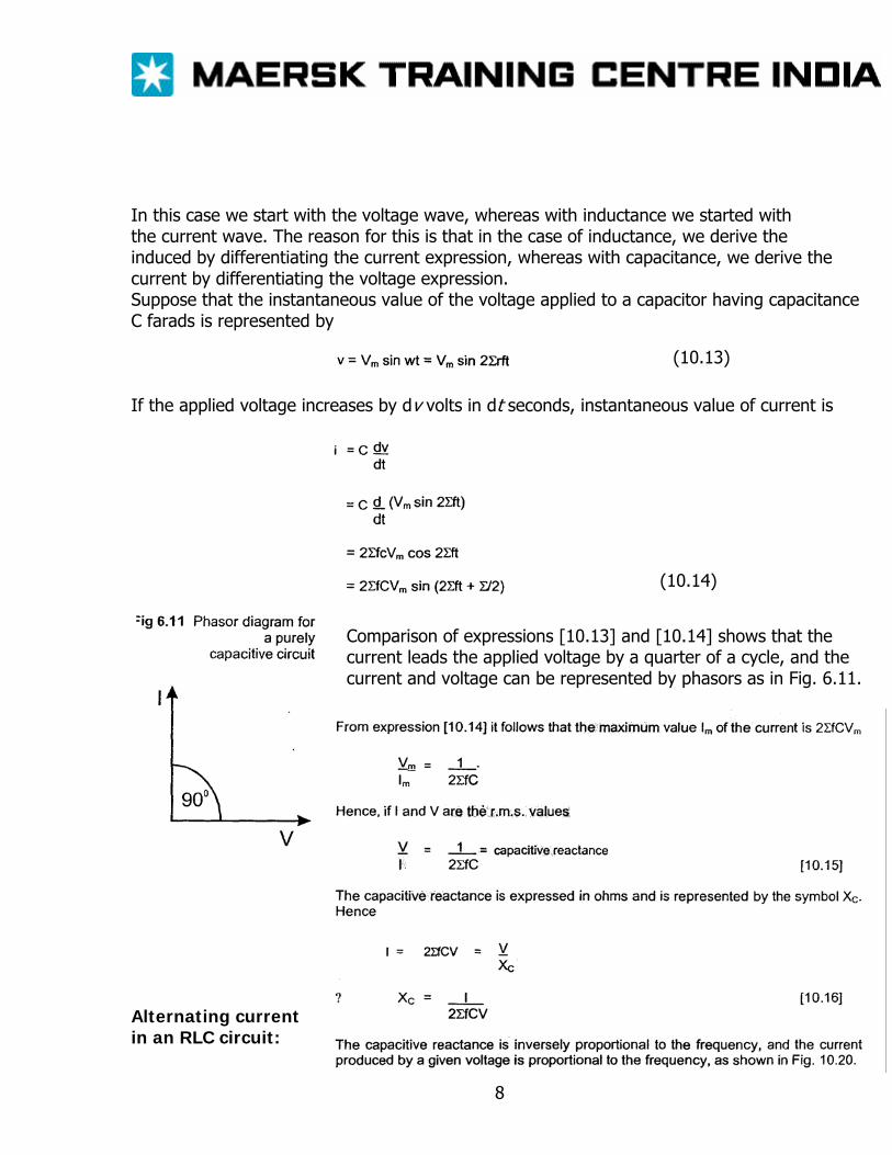
In this case we start with the voltage wave, whereas with inductance we started with the current wave. The reason for this is that in the case of inductance, we derive the induced by differentiating the current expression, whereas with capacitance, we derive the current by differentiating the voltage expression. Suppose that the instantaneous value of the voltage applied to a capacitor having capacitance C farads is represented by
(10.13)
If the applied voltage increases by dv volts in dt seconds, instantaneous value of current is
(10.14)
Comparison of expressions [10.13] and [10.14] shows that the current leads the applied voltage by a quarter of a cycle, and the current and voltage can be represented by phasors as in Fig. 6.11.
Alternating current in an RLC circuit:
8
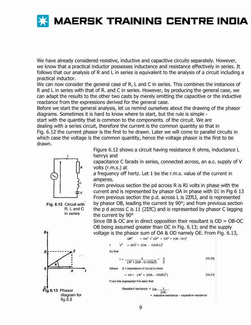
We have already considered resistive, inductive and capacitive circuits separately. However, we know that a practical inductor possesses inductance and resistance effectively in series. It follows that our analysis of R and L in series is equivalent to the analysis of a circuit including a practical inductor. We can now consider the general case of R, L and C in series. This combines the instances of R and L in series with that of R. and C in series. However, by producing the general case, we can adapt the results to the other two casts by merely emitting the capacitive or the inductive reactance from the expressions derived for the general case. Before we start the general analysis, let us remind ourselves about the drawing of the phasor diagrams. Sometimes it is hard to know where to start, but the rule is simple - start with the quantity that is common to the components. of the circuit. We are dealing with a series circuit, therefore the current is the common quantity so that in Fig. 6.12 the current phasor is the first to he drawn. Later we will come to parallel circuits in which case the voltage is the common quantity, hence the voltage phasor is the first to be drawn.
Figure 6.12 shows a circuit having resistance R ohms, inductance L henrys and capacitance C farads in series, connected across, an a.c. supply of V volts (r.m.s.) at a frequency off hertz. Let 1 be the r.m.s. value of the current in amperes. From previous section the pd across R is RI volts in phase with the current and is represented by phasor OA in phase with 01 in Fig 6 13 From previous section the p.d. across L is 2ΣfLI, and is represented by phasor OB, leading the current by 90°; and from previous section the p d across C is 11 (2ΣfC) and is represented by phasor C lagging the current by 90° Since 0B & OC are in direct opposition their resultant is OD = OB-OC OB being assumed greater than OC in Fig. 6.13; and the supply voltage is the phasor sum of OA & OD namely OE. From Fig. 6.13,
9
POWER IN AC CIRCUITS The Impossible Power When alternating current systems were first introduced, learned scientists claimed that it was impossible to deliver energy by such a means. Their argument was that power transfer would take place during the first half of the cycle - and then it would transfer back during the second half. Curiously there was some truth in what they claimed, but they had overlooked the basic relationship p = I2R. The square of the current means that the power is positive no matter whether the current has a positive or a negative value. But it is only the resistive element that dissipates energy from the circuit. Inductors and capacitors do not dissipate energy, which supports the theory of the impossible power. Let us therefore examine in more detail the energy transfer process, which takes place first in resistive circuits and then in reactive circuits. It was explained that when an alternating current flows through a resistor of R ohms, the average heating effect over a complete cycles l2R watts, where I is the r.m.s. value of the current in amperes.
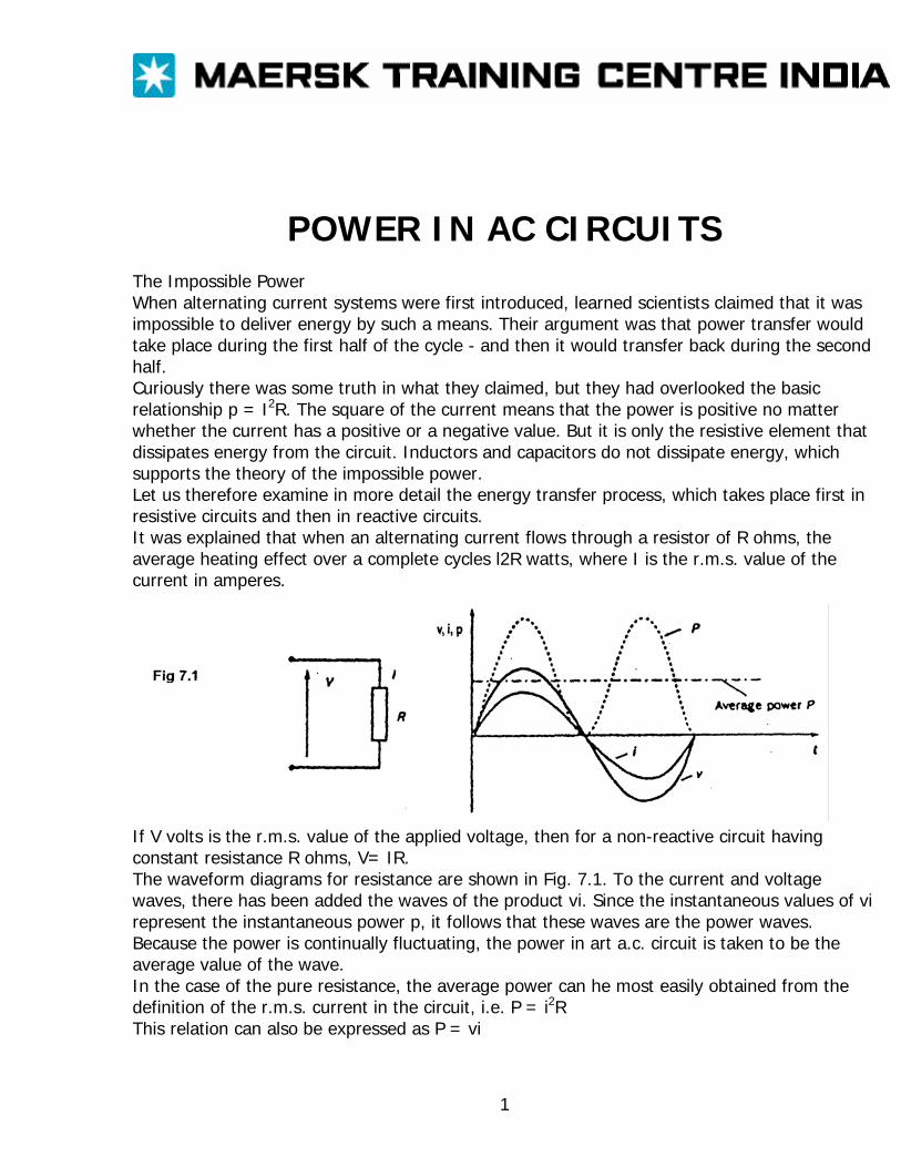
If V volts is the r.m.s. value of the applied voltage, then for a non-reactive circuit having constant resistance R ohms, V= IR. The waveform diagrams for resistance are shown in Fig. 7.1. To the current and voltage waves, there has been added the waves of the product vi. Since the instantaneous values of vi represent the instantaneous power p, it follows that these waves are the power waves. Because the power is continually fluctuating, the power in art a.c. circuit is taken to be the average value of the wave. In the case of the pure resistance, the average power can he most easily obtained from the definition of the r.m.s. current in the circuit, i.e. P = i2R This relation can also be expressed as P = vi
1
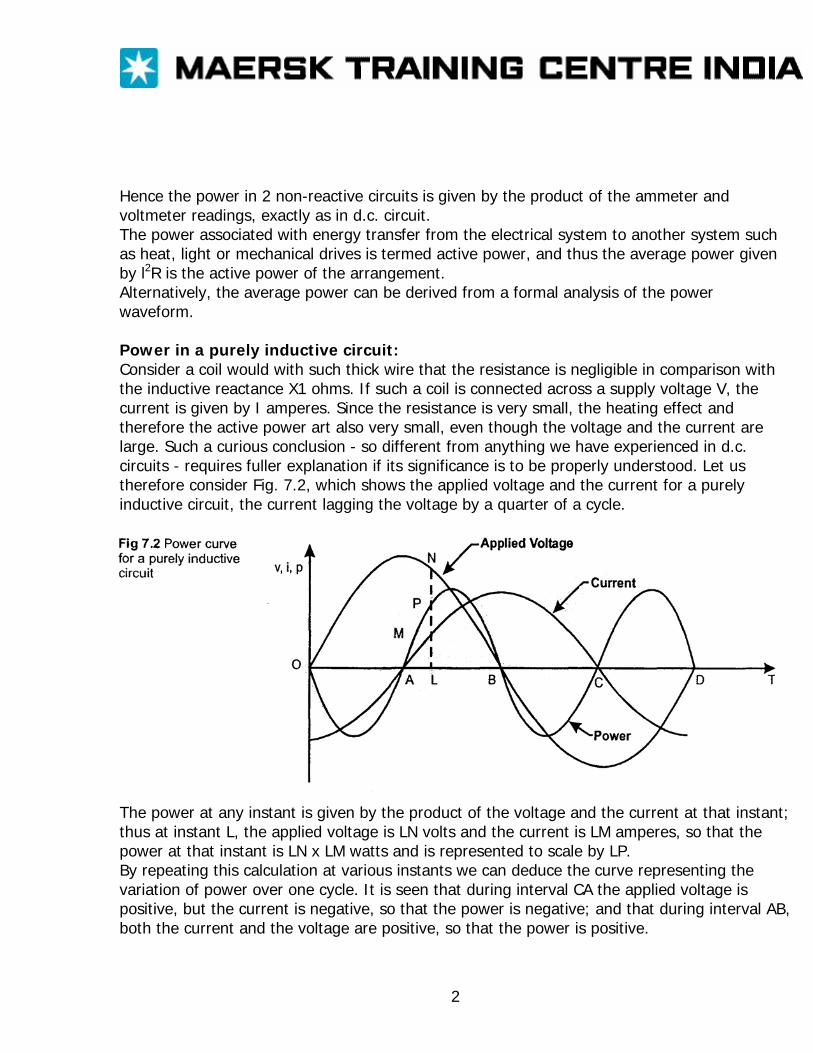
Hence the power in 2 non-reactive circuits is given by the product of the ammeter and voltmeter readings, exactly as in d.c. circuit. The power associated with energy transfer from the electrical system to another system such as heat, light or mechanical drives is termed active power, and thus the average power given by l2R is the active power of the arrangement. Alternatively, the average power can be derived from a formal analysis of the power waveform. Power in a purely inductive circuit: Consider a coil would with such thick wire that the resistance is negligible in comparison with the inductive reactance X1 ohms. If such a coil is connected across a supply voltage V, the current is given by I amperes. Since the resistance is very small, the heating effect and therefore the active power art also very small, even though the voltage and the current are large. Such a curious conclusion - so different from anything we have experienced in d.c. circuits - requires fuller explanation if its significance is to be properly understood. Let us therefore consider Fig. 7.2, which shows the applied voltage and the current for a purely inductive circuit, the current lagging the voltage by a quarter of a cycle.
The power at any instant is given by the product of the voltage and the current at that instant; thus at instant L, the applied voltage is LN volts and the current is LM amperes, so that the power at that instant is LN x LM watts and is represented to scale by LP. By repeating this calculation at various instants we can deduce the curve representing the variation of power over one cycle. It is seen that during interval CA the applied voltage is positive, but the current is negative, so that the power is negative; and that during interval AB, both the current and the voltage are positive, so that the power is positive.
2
The power curve is found to be symmetrical about the horizontal axis OD. Consequently the shaded areas marked ‘-‘are exactly equal to those marked ‘+‘, so that the mean value of the power over the complete cycle OD is zero.
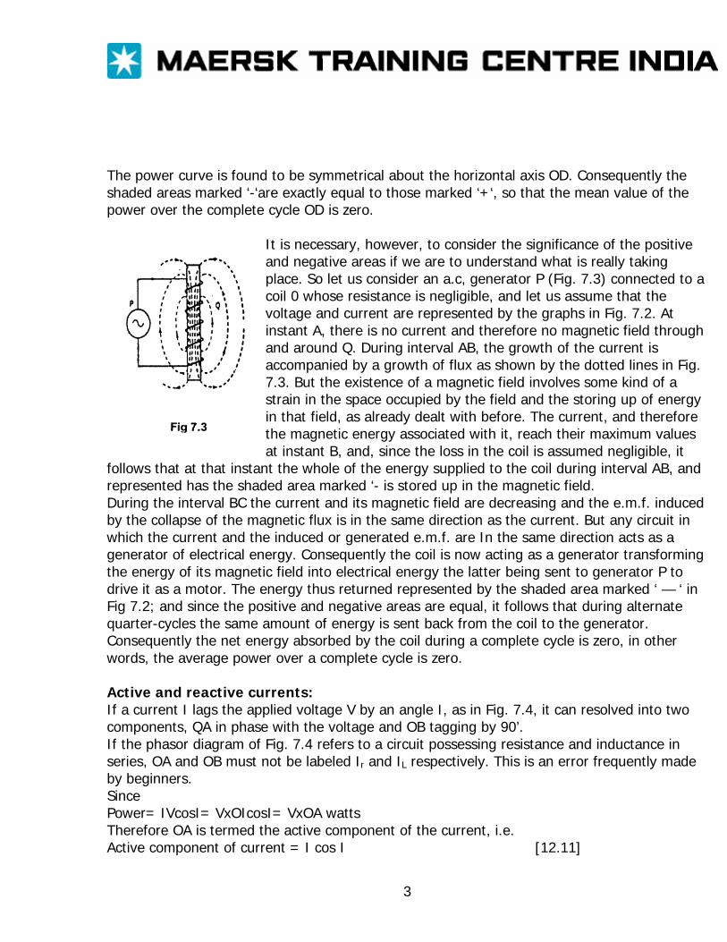
It is necessary, however, to consider the significance of the positive and negative areas if we are to understand what is really taking place. So let us consider an a.c, generator P (Fig. 7.3) connected to a coil 0 whose resistance is negligible, and let us assume that the voltage and current are represented by the graphs in Fig. 7.2. At instant A, there is no current and therefore no magnetic field through and around Q. During interval AB, the growth of the current is accompanied by a growth of flux as shown by the dotted lines in Fig. 7.3. But the existence of a magnetic field involves some kind of a strain in the space occupied by the field and the storing up of energy in that field, as already dealt with before. The current, and therefore the magnetic energy associated with it, reach their maximum values at instant B, and, since the loss in the coil is assumed negligible, it
follows that at that instant the whole of the energy supplied to the coil during interval AB, and represented has the shaded area marked ‘- is stored up in the magnetic field. During the interval BC the current and its magnetic field are decreasing and the e.m.f. induced by the collapse of the magnetic flux is in the same direction as the current. But any circuit in which the current and the induced or generated e.m.f. are In the same direction acts as a generator of electrical energy. Consequently the coil is now acting as a generator transforming the energy of its magnetic field into electrical energy the latter being sent to generator P to drive it as a motor. The energy thus returned represented by the shaded area marked ‘ — ‘ in Fig 7.2; and since the positive and negative areas are equal, it follows that during alternate quarter-cycles the same amount of energy is sent back from the coil to the generator. Consequently the net energy absorbed by the coil during a complete cycle is zero, in other words, the average power over a complete cycle is zero. Active and reactive currents: If a current I lags the applied voltage V by an angle I, as in Fig. 7.4, it can resolved into two components, QA in phase with the voltage and OB tagging by 90’. If the phasor diagram of Fig. 7.4 refers to a circuit possessing resistance and inductance in series, OA and OB must not be labeled Ir and IL respectively. This is an error frequently made by beginners. Since Power= IVcosI= VxOIcosI= VxOA watts Therefore OA is termed the active component of the current, i.e. Active component of current = I cos I [12.11]
3
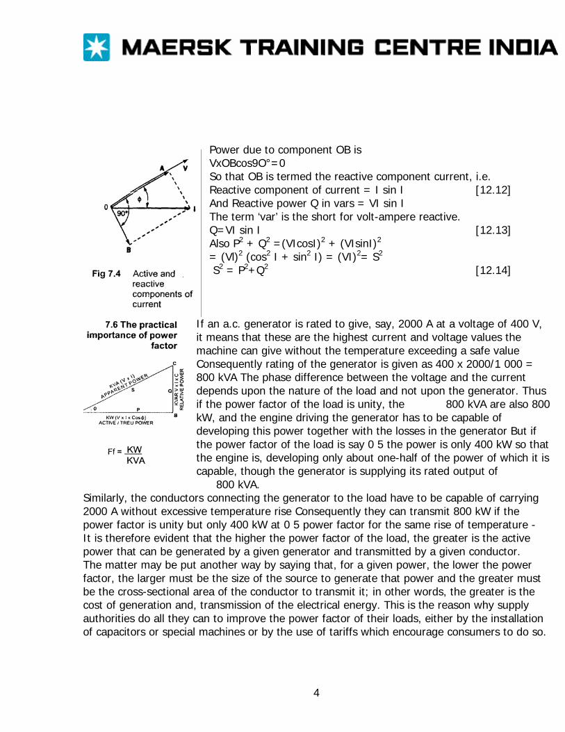
Power due to component OB is VxOBcos9O°=0 So that OB is termed the reactive component current, i.e. Reactive component of current = I sin I [12.12] And Reactive power Q in vars = VI sin I The term ‘var’ is the short for volt-ampere reactive. Q=VI sin I [12.13] Also P2 + Q2 =(VIcosI)2 + (VIsinI)2
= (Vl)2 (cos2 I + sin2 I) = (VI)2= S2
S2 = P2+Q2 [12.14]
If an a.c. generator is rated to give, say, 2000 A at a voltage of 400 V, it means that these are the highest current and voltage values the machine can give without the temperature exceeding a safe value Consequently rating of the generator is given as 400 x 2000/1 000 = 800 kVA The phase difference between the voltage and the current depends upon the nature of the load and not upon the generator. Thus if the power factor of the load is unity, the 800 kVA are also 800 kW, and the engine driving the generator has to be capable of developing this power together with the losses in the generator But if the power factor of the load is say 0 5 the power is only 400 kW so that the engine is, developing only about one-half of the power of which it is capable, though the generator is supplying its rated output of
800 kVA. Similarly, the conductors connecting the generator to the load have to be capable of carrying 2000 A without excessive temperature rise Consequently they can transmit 800 kW if the power factor is unity but only 400 kW at 0 5 power factor for the same rise of temperature - It is therefore evident that the higher the power factor of the load, the greater is the active power that can be generated by a given generator and transmitted by a given conductor. The matter may be put another way by saying that, for a given power, the lower the power factor, the larger must be the size of the source to generate that power and the greater must be the cross-sectional area of the conductor to transmit it; in other words, the greater is the cost of generation and, transmission of the electrical energy. This is the reason why supply authorities do all they can to improve the power factor of their loads, either by the installation of capacitors or special machines or by the use of tariffs which encourage consumers to do so.
4

Measurement of power in single-phase circuit: Since the product of the voltage and current in an a.c. circuit must be multiplied by the power factor to give the active power in watts, the most convenient method of measuring the power is to use a watt-meter. For a general circuit Active power P= VI cos I (watts) Reactive power Q= VI sin I (vars) Apparent power S= VI (volt-amperes) Power factor cos I = P/S S2 = P2 +Q2
5
MULTIPHASE SYSTEMS
Disadvantages of the single-phase system: The earliest application of alternating current was for beating the filaments of electric lamps. For this purpose the single-phase system was perfectly satisfactory. Some years later, a.c. motors were developed, and it was found that for this application the single-phase system was not very satisfactory. For instance, the single-phase induction motor - the type most commonly employed - was not self-starting unless it was fitted with an auxiliary winding. By using two separate windings with currents differing in phase by a quarter of a cycle or three windings with currents differing in phase by a third of a cycle, it was found that the induction motor was self-starting and had better efficiency and power factor than the corresponding single-phase machine. The system utilizing two windings is referred to as a two-phase system and that utilizing three windings is referred to as a three-phase system. We shall now consider the three-phase system in detail.
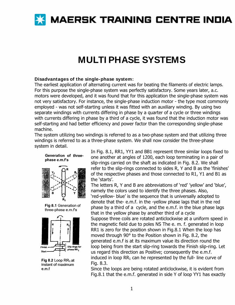
In Fig. 8.1, RR1, YY1 and BB1 represent three similar loops fixed to one another at angles of 1200, each loop terminating in a pair of slip-rings carried on the shaft as indicated in Fig. 8.2. We shall refer to the slip-rings connected to sides R, Y and B as the ‘finishes’ of the respective phases and those connected to R1, Y1 and B1 as the ‘starts’. The letters R, Y and B are abbreviations of ‘red’ ’yellow’ and ‘blue’, namely the colors used to identify the three phases. Also, ‘red-yellow- blue’ is the sequence that is universally adopted to denote that the- e.m.f. in the -yellow phase lags that in the red phase by a third of a cycle, and the e.m.f. in the blue phase lags that in the yellow phase by another third of a cycle Suppose three coils are rotated anticlockwise at a uniform speed in the magnetic field due to poles NS The e. m. f. generated in loop RR1 is zero for the position shown in Fig.8.1 When the loop has moved through 90° to the Position shown in Fig. 8.2, the generated e.m.f is at its maximum value its direction round the loop being from the start slip-ring towards the Finish slip-ring. Let us regard this direction as Positive; consequently the e.m.f. induced in loop RR1 can he represented by the full- line curve of Fig. 8.3. Since the loops are being rotated anticlockwise, it is evident from Fig.8.1 that the e.m.f. generated in side Y of loop YY1 has exactly
1

the same amplitude as that generated in side R, but lags by 120° (or one-third of a cycle). Similarly, the e.m.f. generated in side B of loop BB1 is equal to but lags that in side Y by 1200 . Hence the e.m.fs generated in loops RR1, YY1 and BB1 are represented by the three equally spaced curves of Fig. 8.3, the e.m.f.s being assumed positive when their directions round the loops are from ‘start’ to ‘finish’ of their respective loops. If the instantaneous value of the e.m.f. generated in phase RR1 is represented by eR=eM sin I, then instantaneous e.m.f. in YY1 is ey = Em sin(I - 120°) and instantaneous e.m.f. in BB1 is eB = EB m sin(I - 240°)
Delta connection of three-phase windings: The three phases of Fig 8 1 can for convenience be represented as in Fig 8 4 where the phases are shown isolated from one another; L1, L2 and L3 represent loads connected across the respective phases Since we have assumed the e.m.f.s to be positive when acting from ‘start’ to ‘finish’, they can be represented by the arrows eR, ey and eB in Fig.8.4. This arrangement necessitates six line conductors and is therefore cumbersome and expensive so let us consider how it may be simplified. For instance, let us join ’R1 and Y together as in Fig85, thereby enabling conductors 2 and 3 of Fig. 8.4to be replaced by a single conductor. Similarly, let us join Y1 and B together so that conductors 4 and 5 may be replaced by another single conductor. Before we can proceed to join ‘start’, B, to ‘finish’ R, we have to prove that the resultant e e.m.f f between these two points is zero at every instant so that no circulating current is set up when they are connected together.
B
2
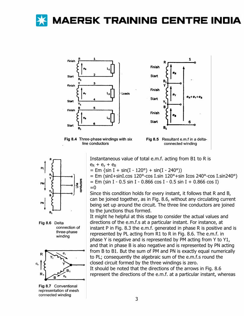
Instantaneous value of total e.m.f. acting from B1 to R is eR + ey + eBB
= Em sin I + sin(I - 120°) + sin(I - 240°)) = Em (sinI+sinI.cos 120°-cos I.sin 120°+sin Icos 240°-cos I.sin240°) = Em (sin I - 0.5 sin I - 0.866 cos I - 0.5 sin I + 0.866 cos I) =0 Since this condition holds for every instant, it follows that R and B, can be joined together, as in Fig. 8.6, without any circulating current being set up around the circuit. The three line conductors are joined to the junctions thus formed. It might he helpful at this stage to consider the actual values and directions of the e.m.f.s at a particular instant. For instance, at instant P in Fig. 8.3 the e.m.f. generated in phase R is positive and is represented by PL acting from R1 to R in Fig. 8.6. The e.m.f. in phase Y is negative and is represented by PM acting from Y to Y1, and that in phase B is also negative and is represented by PN acting from B to B1. But the sum of PM and PN is exactly equal numerically to PL; consequently the algebraic sum of the e.m.f.s round the closed circuit formed by the three windings is zero. It should be noted that the directions of the arrows in Fig. 8.6 represent the directions of the e.m.f. at a particular instant, whereas
3
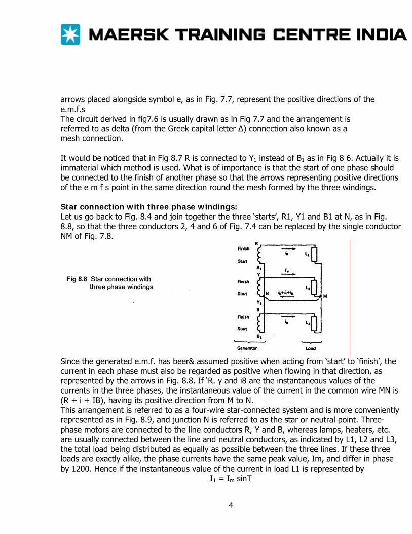
arrows placed alongside symbol e, as in Fig. 7.7, represent the positive directions of the e.m.f.s The circuit derived in fig7.6 is usually drawn as in Fig 7.7 and the arrangement is referred to as delta (from the Greek capital letter Δ) connection also known as a mesh connection. It would be noticed that in Fig 8.7 R is connected to Y1 instead of B1 as in Fig 8 6. Actually it is immaterial which method is used. What is of importance is that the start of one phase should be connected to the finish of another phase so that the arrows representing positive directions of the e m f s point in the same direction round the mesh formed by the three windings. Star connection with three phase windings: Let us go back to Fig. 8.4 and join together the three ‘starts’, R1, Y1 and B1 at N, as in Fig. 8.8, so that the three conductors 2, 4 and 6 of Fig. 7.4 can be replaced by the single conductor NM of Fig. 7.8.
Since the generated e.m.f. has beer& assumed positive when acting from ‘start’ to ‘finish’, the current in each phase must also be regarded as positive when flowing in that direction, as represented by the arrows in Fig. 8.8. If ‘R. y and i8 are the instantaneous values of the currents in the three phases, the instantaneous value of the current in the common wire MN is (R + i + IB), having its positive direction from M to N. This arrangement is referred to as a four-wire star-connected system and is more conveniently represented as in Fig. 8.9, and junction N is referred to as the star or neutral point. Three-phase motors are connected to the line conductors R, Y and B, whereas lamps, heaters, etc. are usually connected between the line and neutral conductors, as indicated by L1, L2 and L3, the total load being distributed as equally as possible between the three lines. If these three loads are exactly alike, the phase currents have the same peak value, Im, and differ in phase by 1200. Hence if the instantaneous value of the current in load L1 is represented by
I1 = Im sinT
4
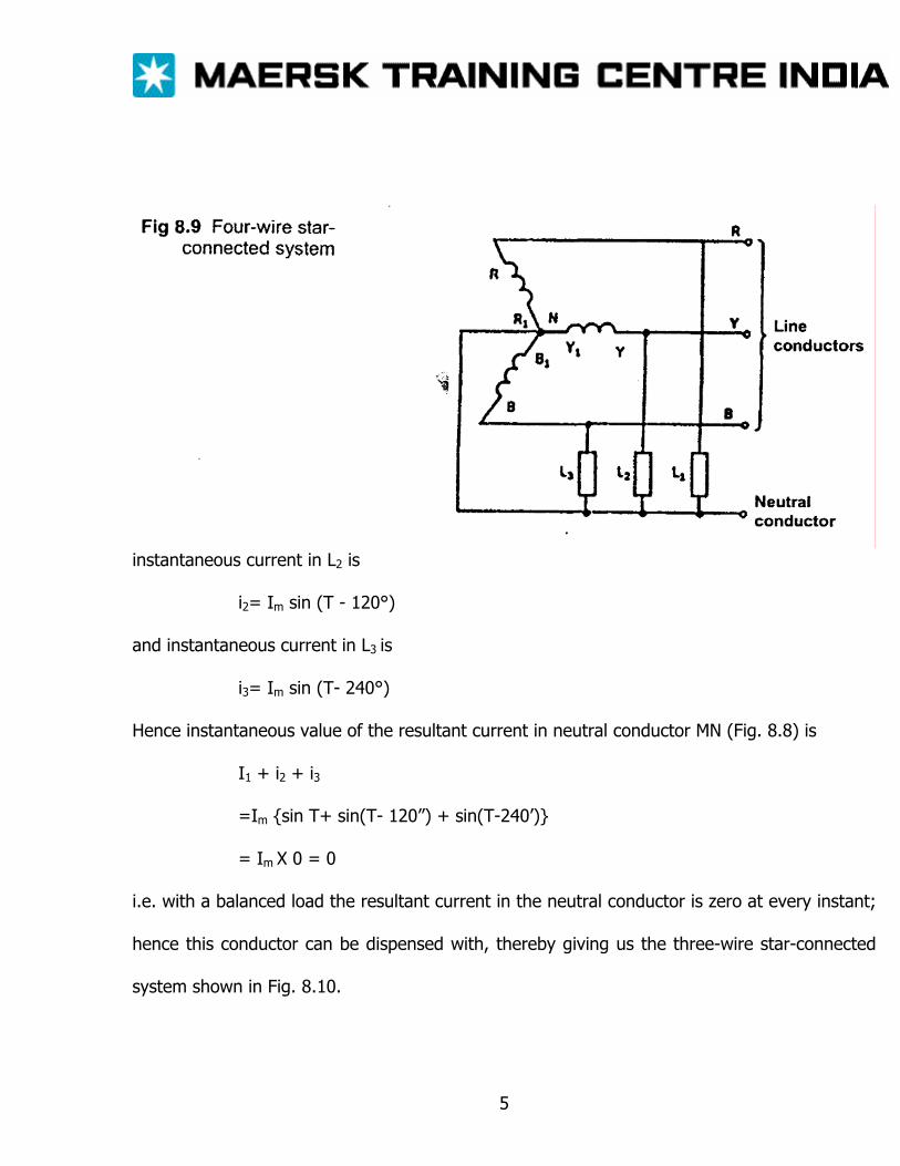
instantaneous current in L2 is
i2= Im sin (T - 120°)
and instantaneous current in L3 is
i3= Im sin (T- 240°)
Hence instantaneous value of the resultant current in neutral conductor MN (Fig. 8.8) is
I1 + i2 + i3
=Im sin T+ sin(T- 120”) + sin(T-240’)
= Im X 0 = 0
i.e. with a balanced load the resultant current in the neutral conductor is zero at every instant;
hence this conductor can be dispensed with, thereby giving us the three-wire star-connected
system shown in Fig. 8.10.
5
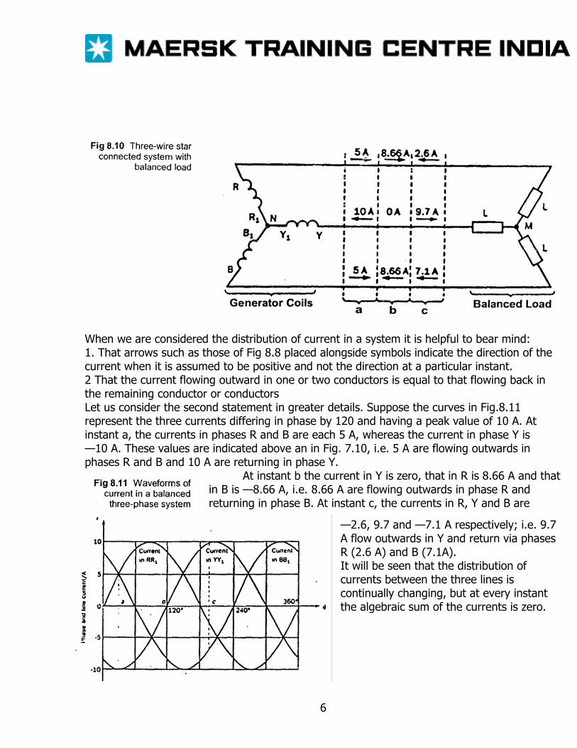
When we are considered the distribution of current in a system it is helpful to bear mind: 1. That arrows such as those of Fig 8.8 placed alongside symbols indicate the direction of the current when it is assumed to be positive and not the direction at a particular instant. 2 That the current flowing outward in one or two conductors is equal to that flowing back in the remaining conductor or conductors Let us consider the second statement in greater details. Suppose the curves in Fig.8.11 represent the three currents differing in phase by 120 and having a peak value of 10 A. At instant a, the currents in phases R and B are each 5 A, whereas the current in phase Y is —10 A. These values are indicated above an in Fig. 7.10, i.e. 5 A are flowing outwards in phases R and B and 10 A are returning in phase Y.
At instant b the current in Y is zero, that in R is 8.66 A and that in B is —8.66 A, i.e. 8.66 A are flowing outwards in phase R and returning in phase B. At instant c, the currents in R, Y and B are
—2.6, 9.7 and —7.1 A respectively; i.e. 9.7 A flow outwards in Y and return via phases R (2.6 A) and B (7.1A). It will be seen that the distribution of currents between the three lines is continually changing, but at every instant the algebraic sum of the currents is zero.
6
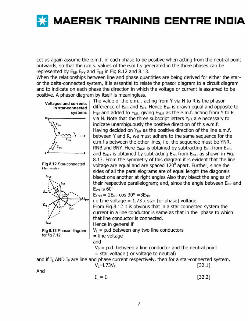
Let us again assume the e.m.f. in each phase to be positive when acting from the neutral point outwards, so that the r.m.s. values of the e.m.f.s generated in the three phases can be represented by ENR.ENY and ENB in Fig 8.12 and 8.13. When the relationships between line and phase quantities are being derived for either the star- or the delta-connected system, it is essential to relate the phasor diagram to a circuit diagram and to indicate on each phase the direction in which the voltage or current is assumed to be positive. A phasor diagram by itself is meaningless.
The value of the e.m.f. acting from Y via N to R is the phasor difference of ENR and ENY. Hence EYN is drawn equal and opposite to ENY and added to ENR, giving EYNR as the e.m.f. acting from Y to R via N. Note that the three subscript letters YNR are necessary to indicate unambiguously the positive direction of this e.m.f. Having decided on YNR as the positive direction of the line e.m.f. between Y and R, we must adhere to the same sequence for the e.m.f.s between the other lines, i.e. the sequence must be YNR, RNB and BNY. Here ERNB is obtained by subtracting ENR from ENB, and EBNY is obtained by subtracting ENR from ENY, as shown in Fig. 8.13. From the symmetry of this diagram it is evident that the line voltage are equal and are spaced 1200 apart. Further, since the sides of all the parallelograms are of equal length the diagonals bisect one another at right angles Also they bisect the angles of their respective parallelogram; and, since the angle between ENR and EVN is 600
EYNR = 2ENR cos 30° =3ENR
i e Line voltage = 1.73 x star (or phase) voltage From Fig.8.12 it is obvious that in a star connected system the current in a line conductor is same as that in the phase to which that line conductor is connected. Hence in general if VL = p.d between any two line conductors = line voltage and VP = p.d. between a line conductor and the neutral point = star voltage ( or voltage to neutral)
and if IL AND IP are line and phase current respectively, then for a star-connected system, VL=l.73VP [32.1]
And IL = IF [32.2]
7
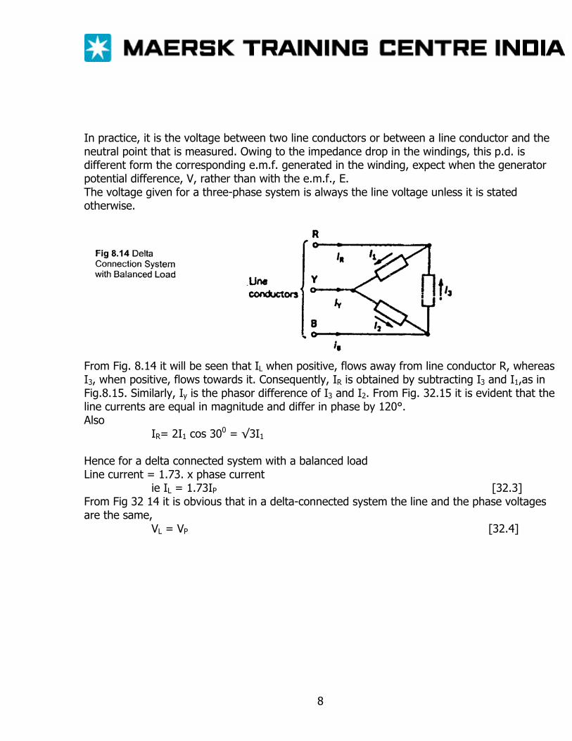
In practice, it is the voltage between two line conductors or between a line conductor and the neutral point that is measured. Owing to the impedance drop in the windings, this p.d. is different form the corresponding e.m.f. generated in the winding, expect when the generator potential difference, V, rather than with the e.m.f., E. The voltage given for a three-phase system is always the line voltage unless it is stated otherwise.
From Fig. 8.14 it will be seen that IL when positive, flows away from line conductor R, whereas I3, when positive, flows towards it. Consequently, IR is obtained by subtracting I3 and I1,as in Fig.8.15. Similarly, Iy is the phasor difference of I3 and I2. From Fig. 32.15 it is evident that the line currents are equal in magnitude and differ in phase by 120°. Also
IR= 2I1 cos 300 = √3I1
Hence for a delta connected system with a balanced load Line current = 1.73. x phase current
ie IL = 1.73IP [32.3] From Fig 32 14 it is obvious that in a delta-connected system the line and the phase voltages are the same,
VL = VP [32.4]
8
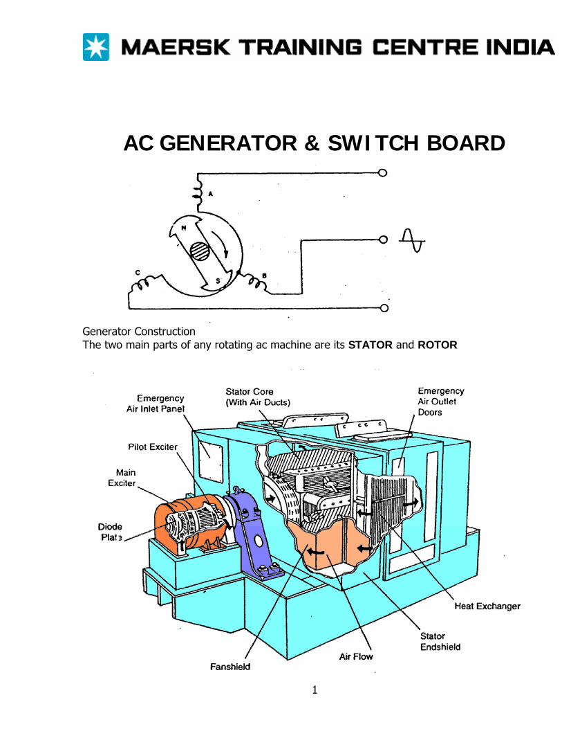
AC GENERATOR & SWITCH BOARD
Generator Construction The two main parts of any rotating ac machine are its STATOR and ROTOR
1
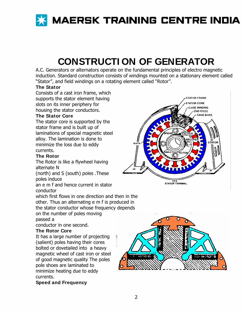
CONSTRUCTION OF GENERATOR A.C. Generators or alternators operate on the fundamental principles of electro magnetic induction. Standard construction consists of windings mounted on a stationary element called “Stator”, and field windings on a rotating element called “Rotor”. The Stator Consists of a cast iron frame, which supports the stator element having slots on its inner periphery for housing the stator conductors. The Stator Core The stator core is supported by the stator frame and is built up of laminations of special magnetic steel alloy. The lamination is done to minimize the loss due to eddy currents. The Rotor The Rotor is like a flywheel having alternate N (north) and S (south) poles .These poles induce an e m f and hence current in stator conductor which first flows in one direction and then in the other. Thus an alternating e m f is produced in the stator conductor whose frequency depends on the number of poles moving passed a conductor in one second. The Rotor Core It has a large number of projecting (salient) poles having their cores bolted or dovetailed into a heavy magnetic wheel of cast iron or steel of good magnetic quality The poles pole shoes are laminated to minimize heating due to eddy currents. Speed and Frequency
2
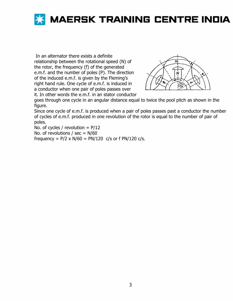
In an alternator there exists a definite relationship between the rotational speed (N) of the rotor, the frequency (f) of the generated e.m.f. and the number of poles (P). The direction of the induced e.m.f. is given by the Fleming’s right hand rule. One cycle of e.m.f. is induced in a conductor when one pair of poles passes over it. In other words the e.m.f. in an stator conductor goes through one cycle in an angular distance equal to twice the pool pitch as shown in the figure. Since one cycle of e.m.f. is produced when a pair of poles passes past a conductor the number of cycles of e.m.f. produced in one revolution of the rotor is equal to the number of pair of poles. No. of cycles / revolution = P/12 No. of revolutions / sec = N/60 frequency = P/2 x N/60 = PN/120 c/s or f PN/120 c/s.
3
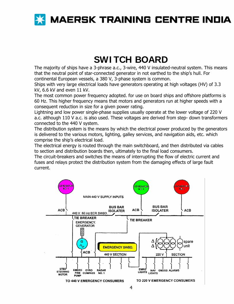
SWITCH BOARD The majority of ships have a 3-phrase a.c., 3-wire, 440 V insulated-neutral system. This means that the neutral point of star-connected generator in not earthed to the ship’s hull. For continental European vessels, a 380 V, 3-phase system is common. Ships with very large electrical loads have generators operating at high voltages (HV) of 3.3 kV, 6.6 kV and even 11 kV. The most common power frequency adopted. for use on board ships and offshore platforms is 60 Hz. This higher frequency means that motors and generators run at higher speeds with a consequent reduction in size for a given power rating. Lightning and low power single-phase supplies usually operate at the lower voltage of 220 V a.c. although 110 V a.c. is also used. These voltages are derived from step- down transformers connected to the 440 V system. The distribution system is the means by which the electrical power produced by the generators is delivered to the various motors, lighting, galley services, and navigation aids, etc. which comprise the ship’s electrical load. The electrical energy is routed through the main switchboard, and then distributed via cables to section and distribution boards then, ultimately to the final load consumers. The circuit-breakers and switches the means of interrupting the flow of electric current and fuses and relays protect the distribution system from the damaging effects of large fault current.
4
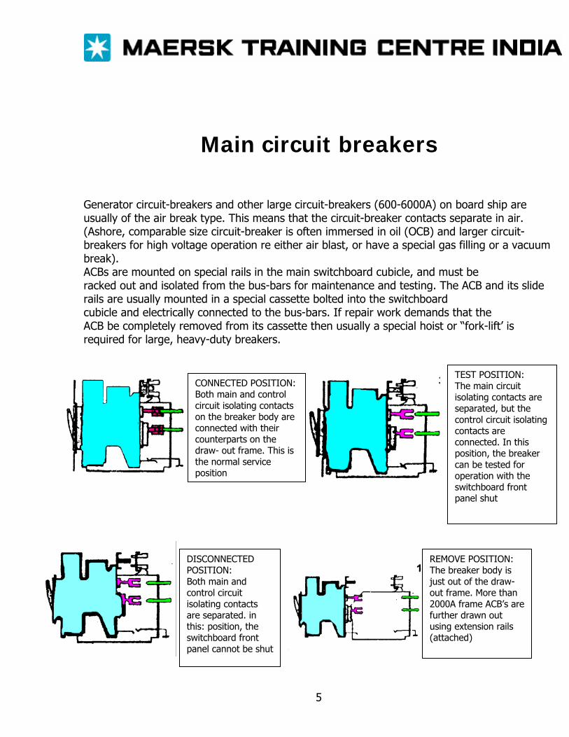
Main circuit breakers Generator circuit-breakers and other large circuit-breakers (600-6000A) on board ship are usually of the air break type. This means that the circuit-breaker contacts separate in air. (Ashore, comparable size circuit-breaker is often immersed in oil (OCB) and larger circuit-breakers for high voltage operation re either air blast, or have a special gas filling or a vacuum break). ACBs are mounted on special rails in the main switchboard cubicle, and must be racked out and isolated from the bus-bars for maintenance and testing. The ACB and its slide rails are usually mounted in a special cassette bolted into the switchboard cubicle and electrically connected to the bus-bars. If repair work demands that the ACB be completely removed from its cassette then usually a special hoist or “fork-lift’ is required for large, heavy-duty breakers.
CONNECTED POSITION: Both main and control circuit isolating contacts on the breaker body are connected with their counterparts on the draw- out frame. This is the normal service position
TEST POSITION: The main circuit isolating contacts are separated, but the control circuit isolating contacts are connected. In this position, the breaker can be tested for operation with the switchboard front panel shut
DISCONNECTED POSITION: Both main and control circuit isolating contacts are separated. in this: position, the switchboard front panel cannot be shut
REMOVE POSITION: The breaker body is just out of the draw-out frame. More than 2000A frame ACB’s are further drawn out using extension rails (attached)
5
The action of whdrawing the “breaker” causes a safety shutter to cover the live bus- bar contacts. Mechanical linkage in the circuit-breaker is quite complex and should not be interfered with expect for maintenance and lubrication as specified by the manufacturer. The main fixed and moving contacts are of copper (sometimes of special arc resistant alloy or silver tipped) and most often silver coated. Main contacts should not be scraped or filed. If the main contacts suffer severe burning they probably require realignment as specified by the manufacturer. Arcing contacts normally suffer burning and may be dressed by a smooth file as recommended by the manufacturer. Carbowndum and emery should not be used — the hard particles can embed themselves in the soft copper contacts and future contact troubles. The arc chutes or arc splitter boxes confine and control the inevitable arc to accelerate arc extinction. These must be removed and inspected for broken parts and erosion of the steel splitter plates. Various types ofclosing mechanism may be fitted: (a) Independent Manual Spring — The spring charge is directly applied by manual depression of the closing handle. The last few centimeters of handle movement releases the spring to close the “breaker”. Closing speed is independent of the operator. (b) Motor Wound Stored Charge Spring — Closing spring are charged by a motor/gearbox unit. Spring recharging is automatic following closure of the “breaker”. Breaker closure is operated by a push button. This may be a direct mechanical release of the charged spring or it may initiate an electrical release via a solenoid latch. (c) Hand Wound Stored Charge Spring — This is similar to (b) but with manually charged closing springs. (d) Solenoid — The “breaker” is closed by a de solenoid energized from the generator or bus-bar via a transformer/rectifier unit, contactor, push button and, sometimes, a timing relay. WARNING — Circuit breaker store energy in springs: (a) in store-charge mechanisms in the closing springs and (b) in contact and kick-off springs Extreme care must be exercised when hndlkng circuit breaker w th the closing springs charged or when the ON position Isolated circuit-breakers ep ked out for maintenance should be left with the closing springs ischargedand in”Ihe OFF position
6
Circuit-breakers are held in the “closed” or ON position by a mechanical latch The breaker is tripped by releasing this latch allowing the kick off springs and contact pressure to force the contacts open. Tripping can be initiated: (a) Manually — a push button with mechanical linkage trips the latch (b) Under voltage trip coil (trip when de-energized). (c) Over current/Short-circuit trip device (trip when energized). (d) Solenoid trip coil — when energized by a remote switch or relay (such as an electronic over current relay). Mechanical interlocks are fitted to ACBs to prevent racking out if still in the ON position. Care must be taken not to exert “undue force” if the breaker will not move — otherwise damage may be caused to the interlocks and other mechanical parts. Dangers of explosion and fire may also result from such action. Electrical interlock switches are connected into circuit-breaker control circuits to prevent incorrect sequence operation, e.g. when a shore-supply breaker is closed onto a switchboard. The ship’s generator breaker are usually interlocked OFF to prevent parallel running of a ship’s generator and the shore supply.
7
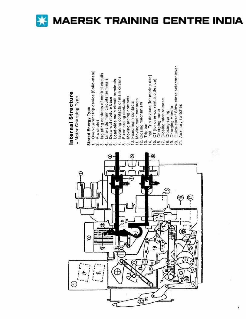
8
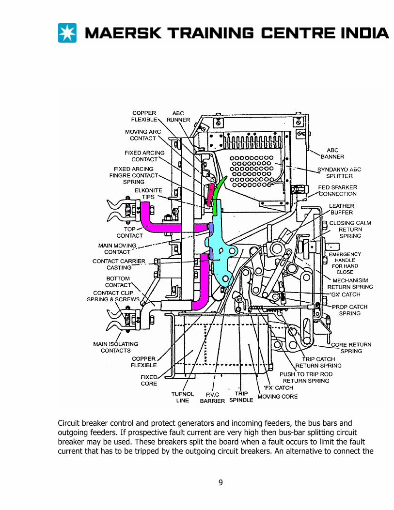
Circuit breaker control and protect generators and incoming feeders, the bus bars and outgoing feeders. If prospective fault current are very high then bus-bar splitting circuit breaker may be used. These breakers split the board when a fault occurs to limit the fault current that has to be tripped by the outgoing circuit breakers. An alternative to connect the
9
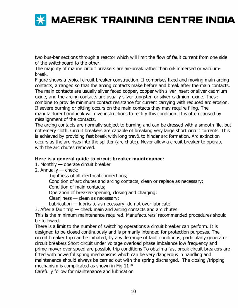
two bus-bar sections through a reactor which will limit the flow of fault current from one side of the switchboard to the other. The majority of marine circuit breakers are air-break rather than oil-immersed or vacuum-break. Figure shows a typical circuit breaker construction. It comprises fixed and moving main arcing contacts, arranged so that the arcing contacts make before and break after the main contacts. The main contacts are usually silver faced copper, copper with silver insert or silver cadmium oxide, and the arcing contacts are usually silver tungsten or silver cadmium oxide. These combine to provide minimum contact resistance for current carrying with reduced arc erosion. If severe burning or pitting occurs on the main contacts they may require filing. The manufacturer handbook will give instructions to rectify this condition. It is often caused by misalignment of the contacts. The arcing contacts are normally subject to burning and can be dressed with a smooth file, but not emery cloth. Circuit breakers are capable of breaking very large short circuit currents. This is achieved by providing fast break with long trav& to hinder arc formation. Arc extinction occurs as the arc rises into the splitter (arc chute). Never allow a circuit breaker to operate with the arc chutes removed. Here is a general guide to circuit breaker maintenance: 1. Monthly — operate circuit breaker 2. Annually — check:
Tightness of all electrical connections; Condition of arc chutes and arcing contacts, clean or replace as necessary; Condition of main contacts; Operation of breaker-opening, closing and charging; Cleanliness — clean as necessary; Lubrication — lubricate as necessary; do not over lubricate.
3. After a fault trip — check main and arcing contacts and arc chutes. This is the minimum maintenance required. Manufacturers’ recommended procedures should be followed. There is a limit to the number of switching operations a circuit breaker can perform. It is designed to be closed continuously and is primarily intended for protection purposes. The circuit breaker trip can be initiated, by a wide range of fault conditions, particularly generator circuit breakers Short circuit under voltage overload phase imbalance low frequency and prime-mover over speed are possible trip conditions To obtain a fast break circuit breakers are fitted with powerful spring mechanisms which can be very dangerous in handling and maintenance should always be carried out with the spring discharged. The closing /tripping mechanism is complicated as shown in Fig 11 * Carefully follow for maintenance and lubrication
10
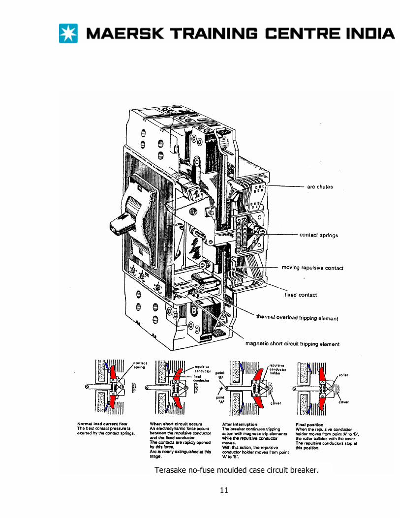
Terasake no-fuse moulded case circuit breaker.
11
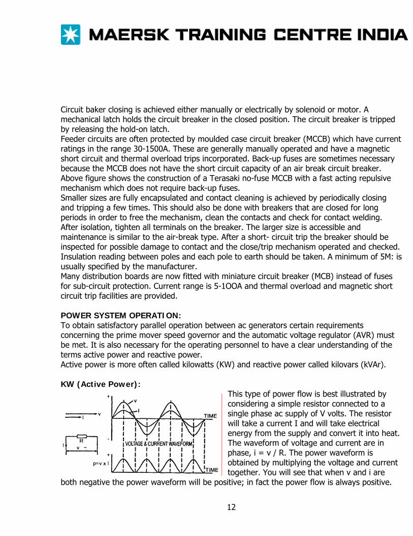
Circuit baker closing is achieved either manually or electrically by solenoid or motor. A mechanical latch holds the circuit breaker in the closed position. The circuit breaker is tripped by releasing the hold-on latch. Feeder circuits are often protected by moulded case circuit breaker (MCCB) which have current ratings in the range 30-1500A. These are generally manually operated and have a magnetic short circuit and thermal overload trips incorporated. Back-up fuses are sometimes necessary because the MCCB does not have the short circuit capacity of an air break circuit breaker. Above figure shows the construction of a Terasaki no-fuse MCCB with a fast acting repulsive mechanism which does not require back-up fuses. Smaller sizes are fully encapsulated and contact cleaning is achieved by periodically closing and tripping a few times. This should also be done with breakers that are closed for long periods in order to free the mechanism, clean the contacts and check for contact welding. After isolation, tighten all terminals on the breaker. The larger size is accessible and maintenance is similar to the air-break type. After a short- circuit trip the breaker should be inspected for possible damage to contact and the close/trip mechanism operated and checked. Insulation reading between poles and each pole to earth should be taken. A minimum of 5M: is usually specified by the manufacturer. Many distribution boards are now fitted with miniature circuit breaker (MCB) instead of fuses for sub-circuit protection. Current range is 5-1OOA and thermal overload and magnetic short circuit trip facilities are provided. POWER SYSTEM OPERATION: To obtain satisfactory parallel operation between ac generators certain requirements concerning the prime mover speed governor and the automatic voltage regulator (AVR) must be met. It is also necessary for the operating personnel to have a clear understanding of the terms active power and reactive power. Active power is more often called kilowatts (KW) and reactive power called kilovars (kVAr). KW (Active Power):
This type of power flow is best illustrated by considering a simple resistor connected to a single phase ac supply of V volts. The resistor will take a current I and will take electrical energy from the supply and convert it into heat. The waveform of voltage and current are in phase, i = v / R. The power waveform is obtained by multiplying the voltage and current together. You will see that when v and i are
both negative the power waveform will be positive; in fact the power flow is always positive.
12
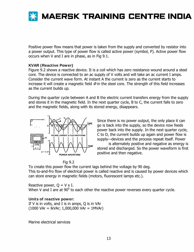
Positive power flow means that power is taken from the supply and converted by resistor into a power output. This type of power flow is called active power (symbol, P). Active power flow occurs when V and I are in phase, as in Fig 9.1. KVAR (Reactive Power) Figure 9.2 shows a reactive device. It is a coil which has zero resistance wound around a steel core. The device is connected to an ac supply of V volts and will take an ac current I amps. Consider the current wave form. At instant A the current is zero as the current starts to increase it will create a magnetic field Φ in the steel core. The strength of this field increases as the current builds up. During the quarter cycle between A and B the electric current transfers energy from the supply and stores it in the magnetic field. In the next quarter cycle, B to C, the current falls to zero and the magnetic fields, along with its stored energy, disappears.
Since there is no power output, the only place it can go is back into the supply, so the device now feeds power back into the supply. In the next quarter cycle, C to D, the current builds up again and power flow is supply—devices and the process repeat itself. Power is alternately positive and negative as energy is stored and discharged. So the power waveform is first positive and then negative.
Fig 9.2 To create this power flow the current lags behind the voltage by 90 deg. This to-and-fro flow of electrical power is called reactive and is caused by power devices which can store energy in magnetic fields (motors, fluorescent lamps etc.). Reactive power, Q = V x I. When V and I are at 900 to each other the reactive power reverses every quarter cycle. Units of reactive power: If V is in volts, and I is in amps, Q is in VAr (1000 VAr = lkVAr; 1,000,000 VAr = 1MVAr) Marine electrical services
13
The main electrical services comprising a typical ship’s load would be electric motors, lighting, and heating. All these loads will draw kW from the supply because they all provide power outputs, but motors and fluorescent lighting have coils and steel cores so they also require kVAr. A typical load will require both kW and kVAr simultaneously from the generator. To do this the load draws a current which lags the voltages at an angle Φ, where Φ is somewhere between 0 deg and 90 deg. You will recall that
P = volts x amps in phase, and Q = volts x amps at 90 deg, so P = V.l cos Φ/1000 kW, and Q = V.I sin Φ / 1000 kVAr
Apparent power You will notice from the phasor diagram that there are 3 volt-amp products. a) V x I cos Φ the active power (P) b) V x I sin Φ the reactive power (Q) c) V x I the volts times the actual current a power but not a new type it is just the combination of P and Q and is called the apparent power (S) Apparent power = volts x circuit amps Units of apparent power If V is in volts d I is in amps S is in VA (1000VA = 1 kVA , 1,000,000 VA 1MVA) Power factor If you know the kVA in a system you may need to know how much of it consists of kW. This is indicated by the power factor of the system Power factor= kW/ KVA = VI cos Φ / VI = cos Φ Power in 3-phase systems: In 3-phase systems, the formulae for P,Q and S are the same as for single phase systems except that each formula is multiplied by √3, i.e.: Single phase 3-phase P=VIcosΦ P=√3VIcosΦ Q=VIsinΦ Q=√3 VIsin Φ S=VI S=√3Vi Power factor = cos Φ power factor = cos Φ
14
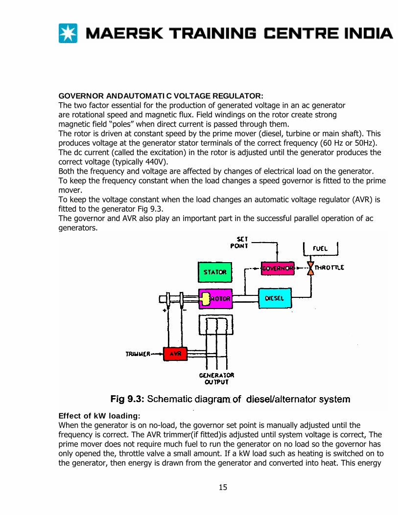
GOVERNOR ANDAUTOMATIC VOLTAGE REGULATOR: The two factor essential for the production of generated voltage in an ac generator are rotational speed and magnetic flux. Field windings on the rotor create strong magnetic field “poles” when direct current is passed through them. The rotor is driven at constant speed by the prime mover (diesel, turbine or main shaft). This produces voltage at the generator stator terminals of the correct frequency (60 Hz or 50Hz). The dc current (called the excitation) in the rotor is adjusted until the generator produces the correct voltage (typically 440V). Both the frequency and voltage are affected by changes of electrical load on the generator. To keep the frequency constant when the load changes a speed governor is fitted to the prime mover. To keep the voltage constant when the load changes an automatic voltage regulator (AVR) is fitted to the generator Fig 9.3. The governor and AVR also play an important part in the successful parallel operation of ac generators.
Effect of kW loading: When the generator is on no-load, the governor set point is manually adjusted until the frequency is correct. The AVR trimmer(if fitted)is adjusted until system voltage is correct, The prime mover does not require much fuel to run the generator on no load so the governor has only opened the, throttle valve a small amount. If a kW load such as heating is switched on to the generator, then energy is drawn from the generator and converted into heat. This energy
15
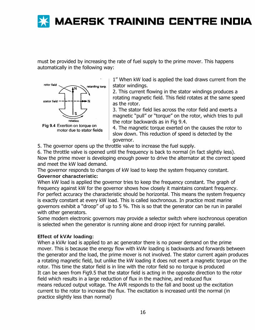
must be provided by increasing the rate of fuel supply to the prime mover. This happens automatically in the following way:
1’’ When kW load is applied the load draws current from the stator windings. 2. This current flowing in the stator windings produces a rotating magnetic field. This field rotates at the same speed as the rotor. 3. The stator field lies across the rotor field and exerts a magnetic “pull” or “torque” on the rotor, which tries to pull the rotor backwards as in Fig 9.4. 4. The magnetic torque exerted on the causes the rotor to slow down. This reduction of speed is detected by the governor.
5. The governor opens up the throttle valve to increase the fuel supply. 6. The throttle valve is opened until the frequency is back to normal (in fact slightly less). Now the prime mover is developing enough power to drive the alternator at the correct speed and meet the kW load demand. The governor responds to changes of kW load to keep the system frequency constant. Governor characteristic: When kW load is applied the governor tries to keep the frequency constant. The graph of frequency against kW for the governor shows how closely it maintains constant frequency. For perfect accuracy the characteristic should be horizontal. This means the system frequency is exactly constant at every kW load. This is called isochronous. In practice most marine governors exhibit a “droop” of up to 5 %. This is so that the generator can be run in parallel with other generators. Some modern electronic governors may provide a selector switch where isochronous operation is selected when the generator is running alone and droop inject for running parallel. Effect of kVAr loading: When a kVAr load is applied to an ac generator there is no power demand on the prime mover. This is because the energy flow with kVAr loading is backwards and forwards between the generator and the load, the prime mover is not involved. The stator current again produces a rotating magnetic field, but unlike the kW loading it does not exert a magnetic torque on the rotor. This time the stator field is in line with the rotor field so no torque is produced It can be seen from Fig9.5 that the stator field is acting in the opposite direction to the rotor field which results in a large reduction of flux in the machine, and reduced flux means reduced output voltage. The AVR responds to the fall and boost up the excitation current to the rotor to increase the flux. The excitation is increased until the normal (in practice slightly less than normal)
16
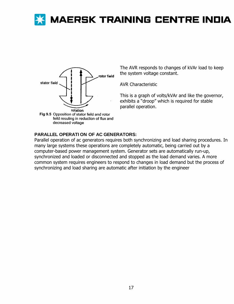
The AVR responds to changes of kVAr load to keep the system voltage constant. AVR Characteristic This is a graph of volts/kVAr and like the governor, exhibits a “droop” which is required for stable parallel operation.
PARALLEL OPERATION OF AC GENERATORS: Parallel operation of ac generators requires both synchronizing and load sharing procedures. In many large systems these operations are completely automatic, being carried out by a computer-based power management system. Generator sets are automatically run-up, synchronized and loaded or disconnected and stopped as the load demand varies. A more common system requires engineers to respond to changes in load demand but the process of synchronizing and load sharing are automatic after initiation by the engineer
17
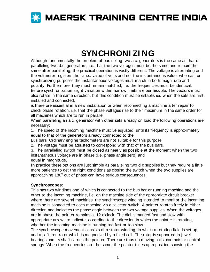
SYNCHRONIZING Although fundamentally the problem of paralleling two a.c. generators is the same as that of paralleling two d.c. generators, i.e. that the two voltages must be the same and remain the same after paralleling, the practical operation is vastly different. The voltage is alternating and the voltmeter registers the r.m.s. value of volts and not the instantaneous value, whereas for synchronizing purposes the instantaneous voltages must match in both magnitude and polarity. Furthermore, they must remain matched, i.e. the frequencies must be identical. Before synchronization slight variation within narrow limits are permissible. The vectors must also rotate in the same direction, but this condition must be established when the sets are first installed and connected. is therefore essential in a new installation or when reconnecting a machine after repair to check phase rotation, i.e. that the phase voltages rise to their maximum in the same order for all machines which are to run in parallel. When paralleling an a.c. generator with other sets already on load the following operations are necessary: 1. The speed of the incoming machine must Le adjusted, until its frequency is approximately equal to that of the generators already connected to the Bus bars. Ordinary engine tachometers are not suitable for this purpose. 2. The voltage must be adjusted to correspond with that of the bus bars. 3. The paralleling switch must be closed as nearly as possible at the moment when the two instantaneous voltage are in phase (i.e. phase angle zero) and equal in magnitude. In practice these options are just simple as paralleling two d c supplies but they require a little more patience to get the right conditions as closing the switch when the two supplies are approaching 1800 out of phase can have serious consequences. Synchroscopes: This has two windings one of which is connected to the bus bar or running machine and the other to the incoming machine, i.e. on the machine side of the appropriate circuit breaker where there are several machines, the synchroscope winding intended to monitor the incoming machine is connected to each machine via a selector switch. A pointer rotates freely in either direction and indicates the phase angle between the two voltage supplies. When the voltages are in phase the pointer remains at 12 o’clock. The dial is marked fast and slow with appropriate arrows to indicate, according to the direction in which the pointer is rotating, whether the incoming machine is running too fast or too slow. The synchroscope movement consists of a stator winding, in which a rotating field is set up, and a soft-iron rotor which is magnetized by a fixed coil. The rotor is supported in jewel bearings and its shaft carries the pointer. There are thus no moving coils, contacts or control springs. When the frequencies are the same, the pointer takes up a position showing the
1
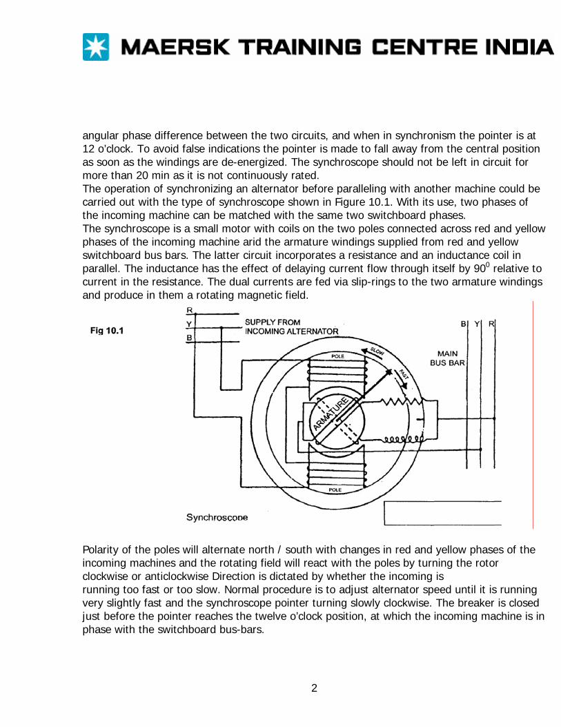
angular phase difference between the two circuits, and when in synchronism the pointer is at 12 o’clock. To avoid false indications the pointer is made to fall away from the central position as soon as the windings are de-energized. The synchroscope should not be left in circuit for more than 20 min as it is not continuously rated. The operation of synchronizing an alternator before paralleling with another machine could be carried out with the type of synchroscope shown in Figure 10.1. With its use, two phases of the incoming machine can be matched with the same two switchboard phases. The synchroscope is a small motor with coils on the two poles connected across red and yellow phases of the incoming machine arid the armature windings supplied from red and yellow switchboard bus bars. The latter circuit incorporates a resistance and an inductance coil in parallel. The inductance has the effect of delaying current flow through itself by 900 relative to current in the resistance. The dual currents are fed via slip-rings to the two armature windings and produce in them a rotating magnetic field.
Polarity of the poles will alternate north / south with changes in red and yellow phases of the incoming machines and the rotating field will react with the poles by turning the rotor clockwise or anticlockwise Direction is dictated by whether the incoming is running too fast or too slow. Normal procedure is to adjust alternator speed until it is running very slightly fast and the synchroscope pointer turning slowly clockwise. The breaker is closed just before the pointer reaches the twelve o’clock position, at which the incoming machine is in phase with the switchboard bus-bars.
2
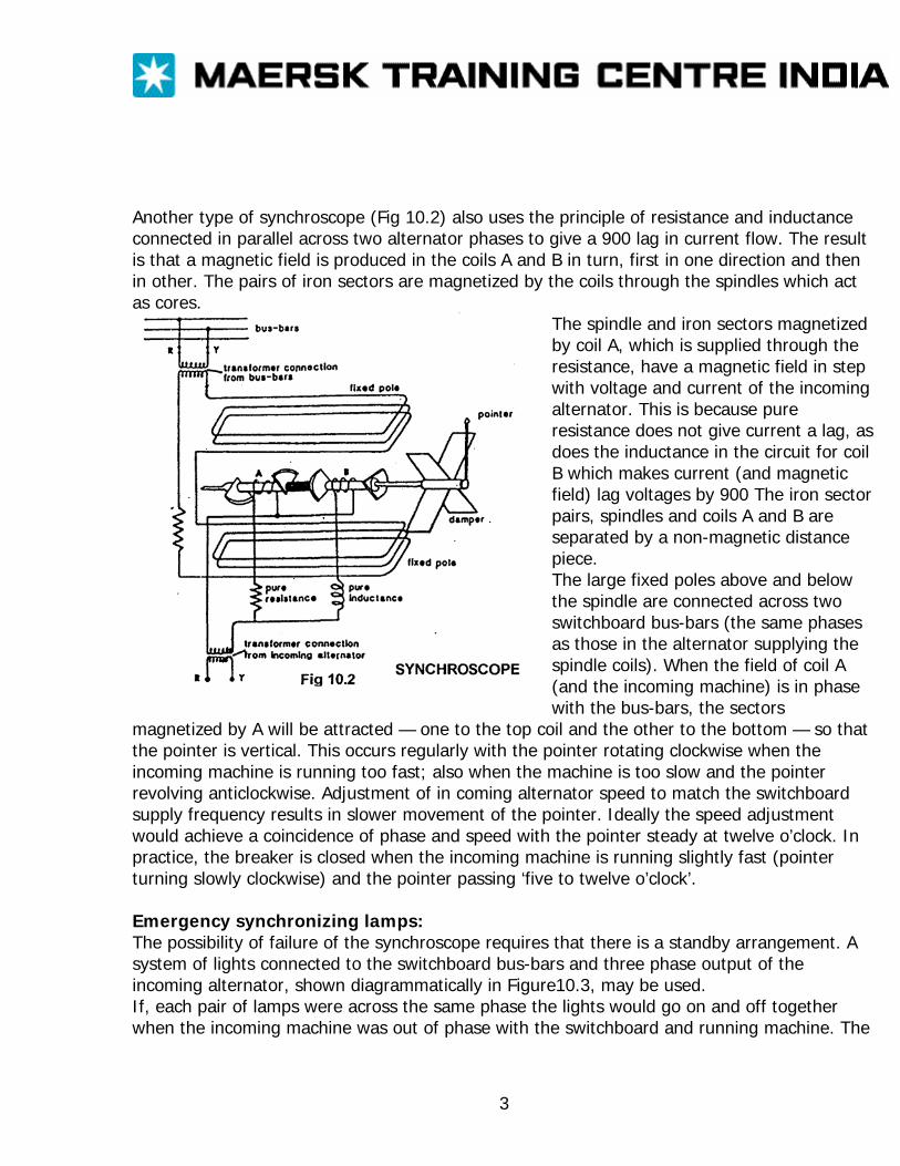
Another type of synchroscope (Fig 10.2) also uses the principle of resistance and inductance connected in parallel across two alternator phases to give a 900 lag in current flow. The result is that a magnetic field is produced in the coils A and B in turn, first in one direction and then in other. The pairs of iron sectors are magnetized by the coils through the spindles which act as cores.
The spindle and iron sectors magnetized by coil A, which is supplied through the resistance, have a magnetic field in step with voltage and current of the incoming alternator. This is because pure resistance does not give current a lag, as does the inductance in the circuit for coil B which makes current (and magnetic field) lag voltages by 900 The iron sector pairs, spindles and coils A and B are separated by a non-magnetic distance piece. The large fixed poles above and below the spindle are connected across two switchboard bus-bars (the same phases as those in the alternator supplying the spindle coils). When the field of coil A (and the incoming machine) is in phase with the bus-bars, the sectors
magnetized by A will be attracted — one to the top coil and the other to the bottom — so that the pointer is vertical. This occurs regularly with the pointer rotating clockwise when the incoming machine is running too fast; also when the machine is too slow and the pointer revolving anticlockwise. Adjustment of in coming alternator speed to match the switchboard supply frequency results in slower movement of the pointer. Ideally the speed adjustment would achieve a coincidence of phase and speed with the pointer steady at twelve o’clock. In practice, the breaker is closed when the incoming machine is running slightly fast (pointer turning slowly clockwise) and the pointer passing ‘five to twelve o’clock’. Emergency synchronizing lamps: The possibility of failure of the synchroscope requires that there is a standby arrangement. A system of lights connected to the switchboard bus-bars and three phase output of the incoming alternator, shown diagrammatically in Figure10.3, may be used. If, each pair of lamps were across the same phase the lights would go on and off together when the incoming machine was out of phase with the switchboard and running machine. The
3
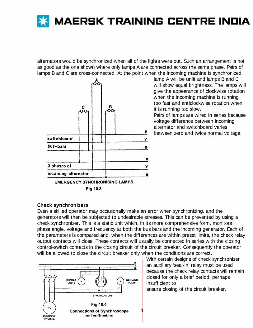
alternators would be synchronized when all of the lights were out. Such an arrangement is not as good as the one shown where only lamps A are connected across the same phase. Pairs of lamps B and C are cross-connected. At the point when the incoming machine is synchronized,
lamp A will be unlit and lamps B and C will show equal brightness. The lamps will give the appearance of clockwise rotation when the incoming machine is running too fast and anticlockwise rotation when it is running too slow. Pairs of lamps are wired in series because voltage difference between incoming alternator and switchboard varies between zero and twice normal voltage.
Check synchronizers Even a skilled operator may occasionally make an error when synchronizing, and the generators will then be subjected to undesirable stresses. This can be prevented by using a check synchronizer. This is a static unit which, in its more comprehensive form, monitors phase angle, voltage and frequency at both the bus bars and the incoming generator. Each of the parameters is compared and, when the differences are within preset limits, the check relay output contacts will close. These contacts will usually be connected in series with the closing control-switch contacts in the closing circuit of the circuit breaker. Consequently the operator will be allowed to close the circuit breaker only when the conditions are correct.
With certain designs of check synchronizer an auxiliary ‘seal-in’ relay must be used because the check relay contacts will remain closed for only a brief period, perhaps insufficient to ensure closing of the circuit breaker.
4
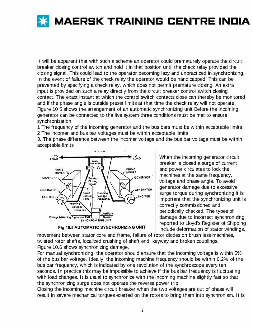
It will be apparent that with such a scheme an operator could prematurely operate the circuit breaker closing control switch and hold it in that position until the check relay provided the closing signal. This could lead to the operator becoming lazy and unpracticed in synchronizing. In the event of failure of the check relay the operator would be handicapped. This can be prevented by specifying a check relay, which does not permit premature closing. An extra input is provided on such a relay directly from the circuit breaker control switch closing contact. The exact instant at which the control switch contacts close can thereby be monitored and if the phase angle is outside preset limits at that time the check relay will not operate. Figure 10 5 shows the arrangement of an automatic synchronizing unit Before the incoming generator can be connected to the live system three conditions must be met to ensure synchronization 1 The frequency of the incoming generator and the bus bars must be within acceptable limits 2 The incomer and bus bar voltages must be within acceptable limits 3. The phase difference between the incomer voltage and the bus bar voltage must be within acceptable limits
When the incoming generator circuit breaker is closed a surge of current and power circulates to lock the machines at the same frequency, voltage and phase angle. To avoid generator damage due to excessive surge torque during synchronizing it is important that the synchronizing unit is correctly commissioned and periodically checked. The types of damage due to incorrect synchronizing reported to Lloyd’s Register of Shipping include deformation of stator windings,
movement between stator core and frame, failure of rotor diodes on brush less machines, twisted rotor shafts, localized crushing of shaft end keyway and broken couplings. Figure 10.6 shows synchronizing damage. For manual synchronizing, the operator should ensure that the incoming voltage is within 5% of the bus bar voltage. Ideally, the incoming machine frequency should be within 0.2% of the bus bar frequency, which is indicated by one revolution of the synchroscope every ten seconds. In practice this may be impossible to achieve if the bus bar frequency is fluctuating with load changes. It is usual to synchronize with the incoming machine slightly fast so that the synchronizing surge does not operate the reverse power trip. Closing the incoming machine circuit breaker when the two voltages are out of phase will result in severe mechanical torques exerted on the rotors to bring them into synchronism. It is
5
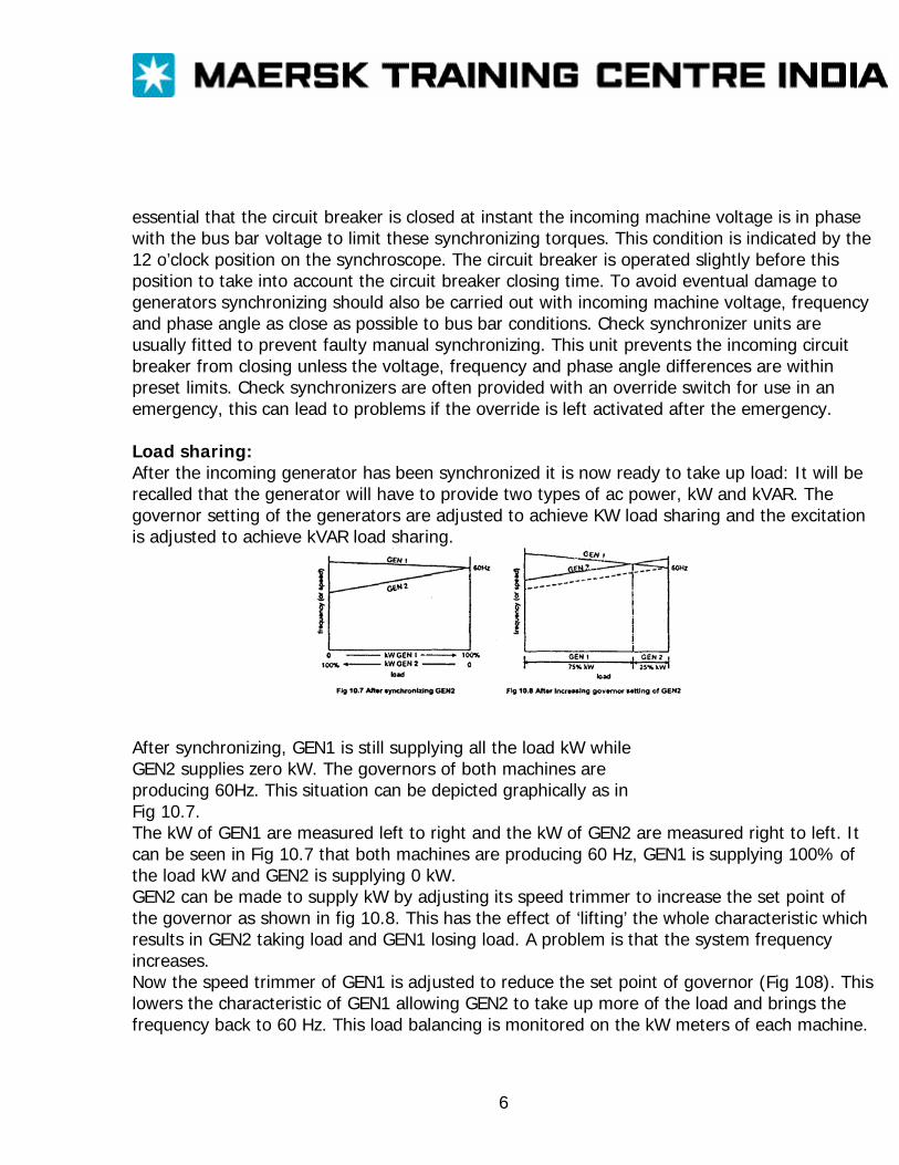
essential that the circuit breaker is closed at instant the incoming machine voltage is in phase with the bus bar voltage to limit these synchronizing torques. This condition is indicated by the 12 o’clock position on the synchroscope. The circuit breaker is operated slightly before this position to take into account the circuit breaker closing time. To avoid eventual damage to generators synchronizing should also be carried out with incoming machine voltage, frequency and phase angle as close as possible to bus bar conditions. Check synchronizer units are usually fitted to prevent faulty manual synchronizing. This unit prevents the incoming circuit breaker from closing unless the voltage, frequency and phase angle differences are within preset limits. Check synchronizers are often provided with an override switch for use in an emergency, this can lead to problems if the override is left activated after the emergency. Load sharing: After the incoming generator has been synchronized it is now ready to take up load: It will be recalled that the generator will have to provide two types of ac power, kW and kVAR. The governor setting of the generators are adjusted to achieve KW load sharing and the excitation is adjusted to achieve kVAR load sharing.
After synchronizing, GEN1 is still supplying all the load kW while GEN2 supplies zero kW. The governors of both machines are producing 60Hz. This situation can be depicted graphically as in Fig 10.7. The kW of GEN1 are measured left to right and the kW of GEN2 are measured right to left. It can be seen in Fig 10.7 that both machines are producing 60 Hz, GEN1 is supplying 100% of the load kW and GEN2 is supplying 0 kW. GEN2 can be made to supply kW by adjusting its speed trimmer to increase the set point of the governor as shown in fig 10.8. This has the effect of ‘lifting’ the whole characteristic which results in GEN2 taking load and GEN1 losing load. A problem is that the system frequency increases. Now the speed trimmer of GEN1 is adjusted to reduce the set point of governor (Fig 108). This lowers the characteristic of GEN1 allowing GEN2 to take up more of the load and brings the frequency back to 60 Hz. This load balancing is monitored on the kW meters of each machine.
6
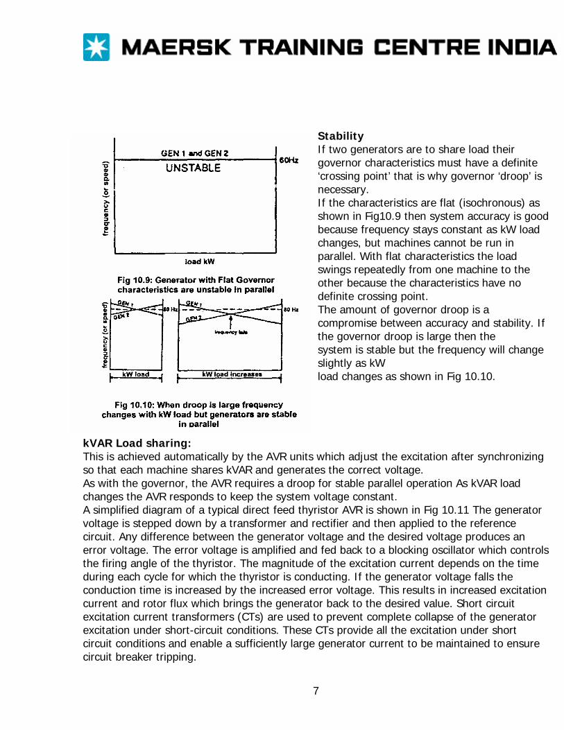
Stability If two generators are to share load their governor characteristics must have a definite ‘crossing point’ that is why governor ‘droop’ is necessary. If the characteristics are flat (isochronous) as shown in Fig10.9 then system accuracy is good because frequency stays constant as kW load changes, but machines cannot be run in parallel. With flat characteristics the load swings repeatedly from one machine to the other because the characteristics have no definite crossing point. The amount of governor droop is a compromise between accuracy and stability. If the governor droop is large then the system is stable but the frequency will change slightly as kW load changes as shown in Fig 10.10.
kVAR Load sharing: This is achieved automatically by the AVR units which adjust the excitation after synchronizing so that each machine shares kVAR and generates the correct voltage. As with the governor, the AVR requires a droop for stable parallel operation As kVAR load changes the AVR responds to keep the system voltage constant. A simplified diagram of a typical direct feed thyristor AVR is shown in Fig 10.11 The generator voltage is stepped down by a transformer and rectifier and then applied to the reference circuit. Any difference between the generator voltage and the desired voltage produces an error voltage. The error voltage is amplified and fed back to a blocking oscillator which controls the firing angle of the thyristor. The magnitude of the excitation current depends on the time during each cycle for which the thyristor is conducting. If the generator voltage falls the conduction time is increased by the increased error voltage. This results in increased excitation current and rotor flux which brings the generator back to the desired value. Short circuit excitation current transformers (CTs) are used to prevent complete collapse of the generator excitation under short-circuit conditions. These CTs provide all the excitation under short circuit conditions and enable a sufficiently large generator current to be maintained to ensure circuit breaker tripping.
7
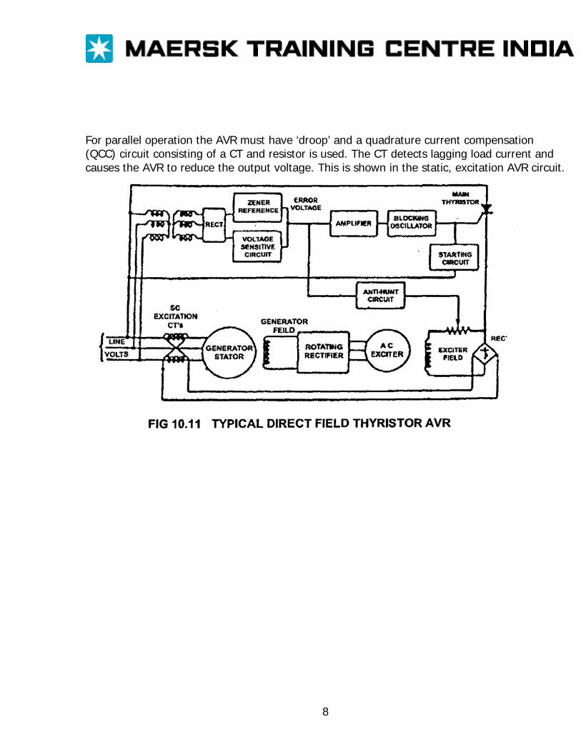
For parallel operation the AVR must have ‘droop’ and a quadrature current compensation (QCC) circuit consisting of a CT and resistor is used. The CT detects lagging load current and causes the AVR to reduce the output voltage. This is shown in the static, excitation AVR circuit.
8
Automatic Voltage Regulators An a.c. generator supplied with constant excitation current produces a voltage that exhibits a pronounced droop with the application of normal ship’s load (i.e. at power factors between unity and zero lagging). This variation is shown in Figure 4.2. The way in which the excitation current must be varied to maintain constant terminal voltage is shown in Figure 4.1. With the aid of certain simplifying assumptions it can be shown that this excitation current is approximately proportional to the sum of two components. The first is constant and in phase with the terminal voltage (this is the no-load excitation current). The second component is proportional to the load current, and leads it by 90 electrical degrees. When the excitation current is obtained from a circuit that performs this vector addition, the generator is said to be compounded. By means of a carefully designed compounding circuit, the voltage variation may be reduced to perhaps ± 2.5% with no further control of the excitation current. However, even this accuracy is not easy to achieve, and further improvement is rendered impossible by a number of effects, which are neglected by the simple theory. Among the most serious of these are magnetic saturation in the generator, and the asymmetry between direct (polar) and quadrature (interpolar) axes in salient pole generators and exciters. Furthermore, there is often some complication involved in the parallel operation of compound generator, because the compounding effect will tend to increase the excitation of the generator carrying the largest reactive load thereby transferring a still larger share of this load to that particular generator For these and other reasons it has become almost universal practice to equip a.c. generators with automatic voltage regulators (a.v.rs) The accuracy of voltage control may then be improved to pera±0.5% in the steady state It also becomes possible to which may sometimes be desirable such as constant voltage per hertz. Component parts Although a.v.rs are usually built on one chassis it is convenient for the purpose of explanation in divide the circuit into a number of blocks each of which performs a distinct function. Following this approach, the a.v.r. maybe considered to consist of: 1. A voltage comparison circuit for the detection of any discrepancy between the generated voltage and its required value. 2. An amplifier and conditioning circuit, which converts the information, received from the voltage comparison circuit into a control signal suitable for actuating the control element. 3. A control element, which varies the excitation current in the manner demanded by the amplifier. 4. Various other circuits which, while not essential to the basis operating principle of the a.v.r., nevertheless improve its performance. These parts will be considered in more detail later. Operating principles:
9
The way in which an a.v.r. controls the excitation of a generator or exciter varies from one model to another, but all schemes fall under one of the following two descriptions: 1. Excitation supply a.v.r. In this arrangement, the a.v.r. supplies the whole of the required excitation current (at least under normal operating conditions). 2. Compounding control a.v.r. In this arrangement, the generator is compounded to produce an excessive excitation current at all times. The function of the a.v.r. is to trim the current down to the correct value. The advantages of the former arrangement are that a particular a.v.r. can be used with a wide range of generators, little or no adjustment being necessary to cope with varying generator characteristics, while good sharing of reactive load is facilitated by the absence of a current-dependent component of excitation. The latter arrangement has the advantage that an a.v.r. with smaller current-carrying components may be employed (provided that the compounding circuit is accurately matched to the generator under control) and that a high forcing voltage is assured by the characteristics of the compounding current transformers. Furthermore, if the a.v.r. should fail to operate, the voltage will remain between limits governed by the degree of compounding. Both types of a.v.r. are produced by various manufacturers, and either type is capable of giving fast voltage recovery times, good voltage stability and accurate sharing of reactive load. Sources of excitation supply With a compounding control a.v.r., the constant part of the excitation current is normally taken from the generator terminals (via a transformer if it is necessary to change the voltage), while the current-dependent part is derived from one or more current transformers connected into the power output circuit of the generator. With an excitation supply a.v.r., the excitation current may be; 1. Taken from the generator terminals as above. 2 Derived from a shaft-mounted pilot exciter (usually a permanent magnet a.c. generator). 3. Taken from an entirely separate supply. If the first method is employed, it will be necessary to arrange for a separate excitation supply generator short-circuit conditions The second method entails an increase in the length of the generator and the third method carries the disadvantage that the generating set becomes dependent on external supplies. However, this is often the most satisfactory system if the generator has to operate over an appreciable voltage range (e.g. constant voltage per hertz for a.c. propulsion duties). Voltage comparison circuit The voltage reference element in all modern a.v.rs is the zener diode. This device is described in’ more detail in Chapter 13. At this stage it is sufficient to say that a zener diode is a semiconductor diode of special design which is connected into the circuit in such a way that it is subjected to a higher reverse voltage than it can withstand. As long as reverse current if
10

flowing, the voltage appearing across the zener diode is almost independent of the current flowing and of the temperature. This voltage forms the standard with which a known fraction of the generated voltage is compared by the a.v.r. Arrangements will obviously differ in detail, but the circuit of Figure 10.12. illustrates the general principle. The generator terminal voltage, transformed if necessary, is rectified by the diode bridge rectifier D. The d.c. output is smoothed by inductor L and capacitor C and applied to the voltage reference bridge consisting of zener diodes Z1 and Z2 and resistors R1 and R2. This bridge is arranged to be balanced when the generator is producing its correct voltage. There is then no output signal to the amplifier. If the generator voltage should fall, the current flowing through the arms of the bridge will also fall, and so too will the voltage across R1 and R2. The voltages across Z1 and Z2 will remain unaltered, however, and terminal A will become negative with respect to terminal B. A rise in generator voltage would produce the opposite effect. Amplifier and conditioning circuit The error voltage produced by the voltage comparison circuit is amplified by a transistor amplifier (which may consist of a single transistor only) and converted, if necessary, into a form suitable for the excitation control element. If this is a thyristor the output would normally consist of a train of pulses, synchronized with the excitation supply voltage, and bearing to it a phase relationship which is controlled by the amplifier. If the excitation control element is a saturable reactor or transformer, the output would consist of a direct current of variable magnitude. Feedback is normally applied across the amplifier to prevent the possibility of instability due to the time delays in the generator and exciter. The amount of feedback can often be varied to give the optimum voltage response to a sudden change in load. Too little feedback will cause the voltage to overshoot, and perhaps to oscillate several times before settling to its steady value. Too much feedback will cause an unnecessarily slow voltage recovery. Amplifier designs vary from one manufacturer to another and from model to model in the range of a particular manufacturer, but the function are similar on all types. Excitation control element: The final stage of the a v r which controls the excitation current may have to handle a current of a few amperes if the controlled field winding is that of a rotating exciter Alternatively, if it controls the main generator field winding, the current may be a few hundred amperes. The most common control element is a thyristor (or silicon-controlled rectifier), which basically blocks the flow of current in both directions until a small current is applied to the ‘gate’ or control terminal. If this occurs when the voltage across thyristor is in the forward direction, the thyristor will begin to conduct and will continue to do so until forward current fall to a very low value. It will then revert to the blocking state.
11
It can be seen that a thyristor is very easily turned on; it can only be turned off by events occurring in the external circuit. The simplest application of a thyristor is therefore producing direct current from an alternating source. As the voltage goes into the negative half-cycle, the current dies away, and the thyristor regains its blocking state. The magnitude of the current is controlled by varying the point in the positive half-cycle at which the thyristor is turned on. Alternative control elements sometimes encountered are the power transistor and the saturable transformer or reactor. This is an iron-cored device carrying the normal a.c. winding and an additional control winding. The magnitude of the direct current applied to the control winding governs the degree of saturation in the iron core, and hence the magnitude of the alternating current. Alternator and system protection Protective devices are built into main alternator breakers to safeguard both the individual alternator and the distribution system against certain faults. Over current protection is by relays which cut power supplies to non-essential services on a preferential basis, as well as breaker overload current trips and instantaneous short current tripping. A reverse power trip is fitted where alternators are intended for parallel operation (in some vessel they are not), unless equivalent protection is provided by other means. Parallel operation of alternators also requires an under- voltage release for the breaker. Over current protection The alternator breaker has an over current trip, but a major consideration is that the supply of power to the switchboard must be maintained if possible. The breaker therefore is arranged to be tripped instantly only in the event of high over current such as that associated with short circuit. When over current is not so high, a delay with inverse time characteristics allows an interval before the breaker is opened. During this time the overload may be cleared. Overload of an alternator may be due to increased switchboard load or to a serious fault causing high current flow. Straight overload (apart from the br1 overload due to starting of motors) is reduced by the preference trips which are designed to shed non-essential switchboard load. Preference trips are operated by relays set at about 110% of normal full load. They open the breakers feeding ventilation fans, air conditioning equipment etc. The non-essential items are disconnected at timed intervals, so reducing alternator load. A serious fault on the distribution side of the switchboard should cause the appropriate supply breaker to open, or fuse to operate, due to over current. Disconnection of faulty equipment will reduce alternator overload. Inverse definite minimum time (IDMT) relay: Accurate inverse time delay characteristics are provided by an induction type relay with construction similar to that of a domestic wattmeter or reverse power relay.
12
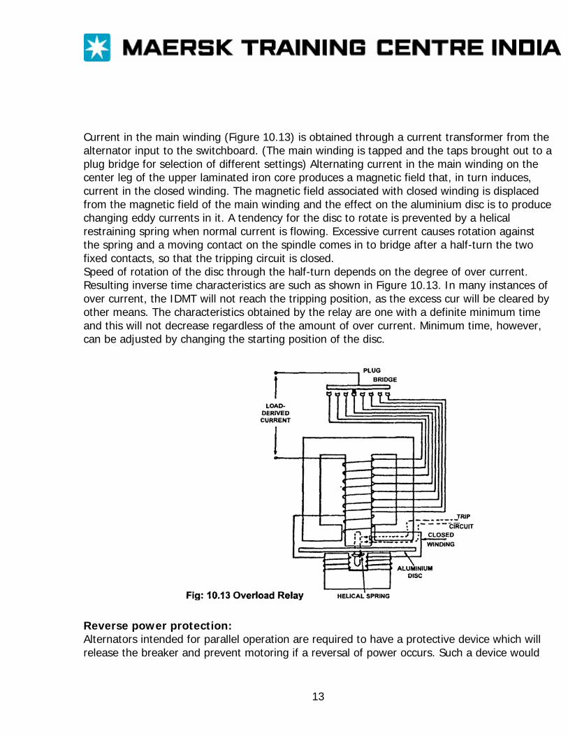
Current in the main winding (Figure 10.13) is obtained through a current transformer from the alternator input to the switchboard. (The main winding is tapped and the taps brought out to a plug bridge for selection of different settings) Alternating current in the main winding on the center leg of the upper laminated iron core produces a magnetic field that, in turn induces, current in the closed winding. The magnetic field associated with closed winding is displaced from the magnetic field of the main winding and the effect on the aluminium disc is to produce changing eddy currents in it. A tendency for the disc to rotate is prevented by a helical restraining spring when normal current is flowing. Excessive current causes rotation against the spring and a moving contact on the spindle comes in to bridge after a half-turn the two fixed contacts, so that the tripping circuit is closed. Speed of rotation of the disc through the half-turn depends on the degree of over current. Resulting inverse time characteristics are such as shown in Figure 10.13. In many instances of over current, the IDMT will not reach the tripping position, as the excess cur will be cleared by other means. The characteristics obtained by the relay are one with a definite minimum time and this will not decrease regardless of the amount of over current. Minimum time, however, can be adjusted by changing the starting position of the disc.
Reverse power protection: Alternators intended for parallel operation are required to have a protective device which will release the breaker and prevent motoring if a reversal of power occurs. Such a device would
13
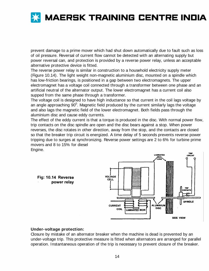
prevent damage to a prime mover which had shut down automatically due to fault such as loss of oil pressure. Reversal of current flow cannot be detected with an alternating supply but power reversal can, and protection is provided by a reverse power relay, unless an acceptable alternative protective device is fitted. The reverse power relay is similar in construction to a household electricity supply meter (Figure 10.14). The light weight non-magnetic aluminium disc, mounted on a spindle which has low-friction bearings, is positioned in a gap between two electromagnets. The upper electromagnet has a voltage coil connected through a transformer between one phase and an artificial neutral of the alternator output. The lower electromagnet has a current coil also supped from the same phase through a transformer. The voltage coil is designed to have high inductance so that current in the coil lags voltage by an angle approaching 900. Magnetic field produced by the current similarly lags the voltage and also lags the magnetic field of the lower electromagnet. Both fields pass through the aluminium disc and cause eddy currents. The effect of the eddy current is that a torque is produced in the disc. With normal power flow, trip contacts on the disc spindle are open and the disc bears against a stop. When power reverses, the disc rotates in other direction, away from the stop, and the contacts are closed so that the breaker trip circuit is energized. A time delay of 5 seconds prevents reverse power tripping due to surges at synchronizing. Reverse power settings are 2 to 6% for turbine prime movers and 8 to 15% for diesel Engine.
Under-voltage protection: Closure by mistake of an alternator breaker when the machine is dead is prevented by an under-voltage trip. This protective measure is fitted when alternators are arranged for parallel operation. Instantaneous operation of the trip is necessary to prevent closure of the breaker.
14
However, an under-voltage trip also gives protection against loss of voltage while the machine is connected to the switchboard. Tripping in this case must be delayed for discrimination purpose, so that if the volt drop is caused by a fault then time is allowed for the appropriate fuse or breaker to operate and voltage to be recovered without loss of the power supply. A.C. earth fault lamps: The sketch shows the arrangement for earth fault indicator lamps on a three-phase a.c. system. Each lamp is connected between one phase and the common neutral point. Closing of the test switch connects the neutral point to earth. An earth on one phase will cause the lamp for that phase to show a dull light or go out, depending on the severity of the fault. Each earth lamp and the resistance in series with it provide a path for current flow to the neutral. An earth on one phase will, when the test switch is closed, allow current flow thorough an easier path than that through the lamp and resistance. The lamp is, therefore, shorted out and will show a dull light or none at all. The great advantage of this check synchronizer is that the skill of the operator is still required to match frequency, volts and phase angle but error are prevented. Other, more simple, variants of the check synchronizer are available which compare only phase angle, not voltage and frequency. Maintenance After a ship enters service it is exceptional for the main bus bars to be made dead; electrical supply of some sort is always needed, even if it consists only of lighting. It therefore follows that the bus bars are continuously alive practically throughout the life of the ship as, even in dry dock; a shore supply will usually be taken. This means that, as far as the main switchboard is concerned routine maintenance work on circuit breakers and other fillings must be carried out with live bus bars and some thought should be given to this in the design and layout, stage. In land practice necessary provision is sometimes made by using duplicate bus bars but space does not permit this in ships. However this equipment has been used in certain offshore installations. On a single bus bar system a limited solution can be achieved by using isolators to sectionalize the switchboard splitting of the lighting feeders can also help. However in large installations draw-out switchgear undoubtedly offers the best solution. Precautions must be observed only to isolate the apparatus but to verify that it is isolated and to ensure that it can not inadvertently be made alive. Where interlock circuits pilot lights or control circuits are involved there is always a risk that although the main circuits may be isolated these auxiliary circuits may still be energized from a separate source, Fatalities have resulted from this cause. Where switches can be locked off it must be seen that this safeguard is used and the keys are removed. Where there are main fuses in the circuit, these might be removed as an additional precaution. Before commencing work it should be verified that the
15
apparatus is actually dead by using a live-line detector. This test should be conducted not only between phases but also between phases and earth. Portable hand lamps used to facilitate the work should be fully insulated with nonmetallic guards, so that there is no risk of shock or short-circuit being caused should they inadvertently come into contact with live parts. When closing any switch by hand, whether in normal operations or when testing, it is a golden rule to do so in one clear positive movement without hesitation. The necessity for cleanliness of all electrical apparatus has previously been emphasized. When apparatus is dismantled for maintenance it should therefore be kept clean and dry. Insulation should be examined for ‘tracking’ and blistering in the vicinity of exposed live metal. If the material is of the bonded laminated type, it should be examined for splits along the laminae. Overheating may be caused by loose connections, poor contact pressure (particularly at fuse contacts), or poor alignment of contacts. On air circuit breakers the condition and alignment of the contacts can be checked by removing the arc chutes to expose the contact assembly. On some high voltage designs the arc chutes tilt forward to provide access. This inspection should be made annually and the mechanism should be lubricated at the same time. Copper contacts may be dressed by using a fine file or fine glass paper, but emery or carborundum paper should not be used. Silver or silver-plated contacts seldom require attention; their black appearance is caused by oxidation, but the oxide is a good conductor. if cleaning is required metal polish may be used. A slight smear of petroleum jelly, particularly on contacts, which are frequently operated, not only helps to preserve good contact but also reduces mechanical abrasion. Excessive application must be avoided as this may cause burning pitting of contacts.
16
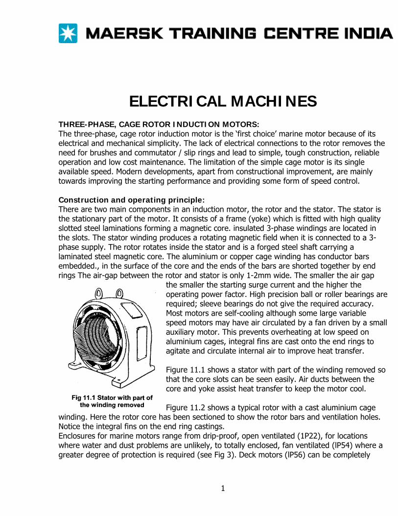
ELECTRICAL MACHINES THREE-PHASE, CAGE ROTOR INDUCTION MOTORS: The three-phase, cage rotor induction motor is the ‘first choice’ marine motor because of its electrical and mechanical simplicity. The lack of electrical connections to the rotor removes the need for brushes and commutator / slip rings and lead to simple, tough construction, reliable operation and low cost maintenance. The limitation of the simple cage motor is its single available speed. Modern developments, apart from constructional improvement, are mainly towards improving the starting performance and providing some form of speed control. Construction and operating principle: There are two main components in an induction motor, the rotor and the stator. The stator is the stationary part of the motor. It consists of a frame (yoke) which is fitted with high quality slotted steel laminations forming a magnetic core. insulated 3-phase windings are located in the slots. The stator winding produces a rotating magnetic field when it is connected to a 3-phase supply. The rotor rotates inside the stator and is a forged steel shaft carrying a laminated steel magnetic core. The aluminium or copper cage winding has conductor bars embedded., in the surface of the core and the ends of the bars are shorted together by end rings The air-gap between the rotor and stator is only 1-2mm wide. The smaller the air gap
the smaller the starting surge current and the higher the operating power factor. High precision ball or roller bearings are required; sleeve bearings do not give the required accuracy. Most motors are self-cooling although some large variable speed motors may have air circulated by a fan driven by a small auxiliary motor. This prevents overheating at low speed on aluminium cages, integral fins are cast onto the end rings to agitate and circulate internal air to improve heat transfer. Figure 11.1 shows a stator with part of the winding removed so that the core slots can be seen easily. Air ducts between the core and yoke assist heat transfer to keep the motor cool. Figure 11.2 shows a typical rotor with a cast aluminium cage
winding. Here the rotor core has been sectioned to show the rotor bars and ventilation holes. Notice the integral fins on the end ring castings. Enclosures for marine motors range from drip-proof, open ventilated (1P22), for locations where water and dust problems are unlikely, to totally enclosed, fan ventilated (lP54) where a greater degree of protection is required (see Fig 3). Deck motors (lP56) can be completely
1
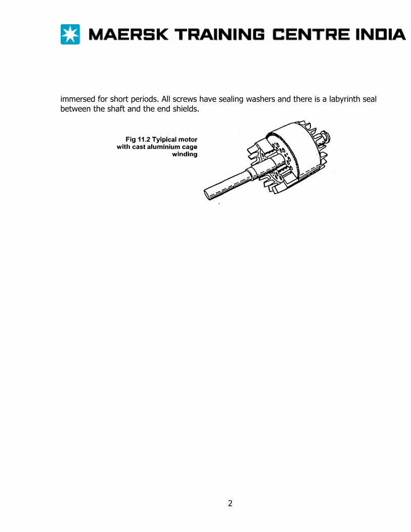
immersed for short periods. All screws have sealing washers and there is a labyrinth seal between the shaft and the end shields.
2
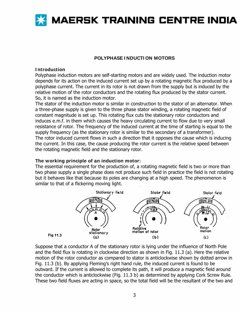
POLYPHASE INDUCTION MOTORS Introduction Polyphase induction motors are self-starting motors and are widely used. The induction motor depends for its action on the induced current set up by a rotating magnetic flux produced by a polyphase current. The current in its rotor is not drawn from the supply but is induced by the relative motion of the rotor conductors and the rotating flux produced by the stator current. So, it is named as the induction motor. The stator of the induction motor is similar in construction to the stator of an alternator. When a three-phase supply is given to the three phase stator winding, a rotating magnetic field of constant magnitude is set up. This rotating flux cuts the stationary rotor conductors and induces e.m.f. in them which causes the heavy circulating current to flow due to very small resistance of rotor. The frequency of the induced current at the time of starting is equal to the supply frequency (as the stationary rotor is similar to the secondary of a transformer). The rotor induced current flows in such a direction that it opposes the cause which is inducing the current. In this case, the cause producing the rotor current is the relative speed between the rotating magnetic field and the stationary rotor. The working principle of an induction motor: The essential requirement for the production of, a rotating magnetic field is two or more than two phase supply a single phase does not produce such field in practice the field is not rotating but it behaves like that because its poles are changing at a high speed. The phenomenon is similar to that of a flickering moving light.
Suppose that a conductor A of the stationary rotor is lying under the influence of North Pole and the field flux is rotating in clockwise direction as shown in Fig. 11.3 (a). Here the relative motion of the rotor conductor as compared to stator is anticlockwise shown by dotted arrow in Fig. 11.3 (b). By applying Fleming’s right hand rule, the induced current is found to be outward. If the current is allowed to complete its path, it will produce a magnetic field around the conductor which is anticlockwise (Fig. 11.3 b) as determined by applying Cork Screw Rule. These two field fluxes are acting in space, so the total field will be the resultant of the two and
3
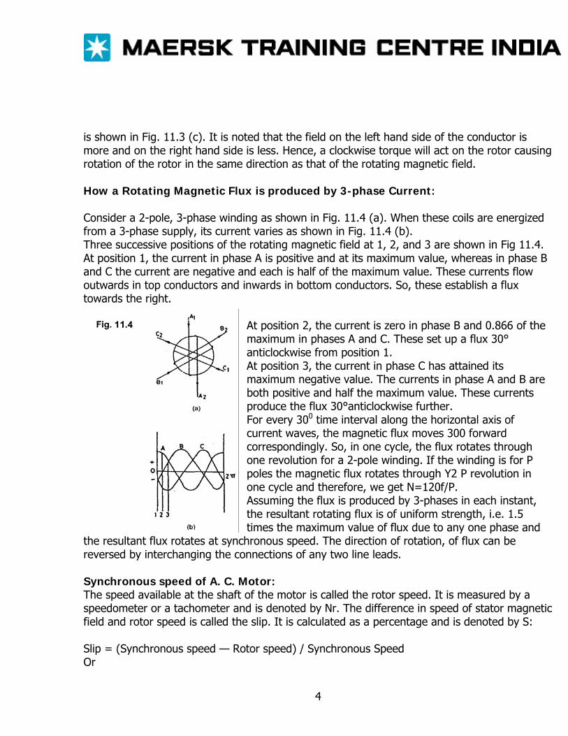
is shown in Fig. 11.3 (c). It is noted that the field on the left hand side of the conductor is more and on the right hand side is less. Hence, a clockwise torque will act on the rotor causing rotation of the rotor in the same direction as that of the rotating magnetic field. How a Rotating Magnetic Flux is produced by 3-phase Current: Consider a 2-pole, 3-phase winding as shown in Fig. 11.4 (a). When these coils are energized from a 3-phase supply, its current varies as shown in Fig. 11.4 (b). Three successive positions of the rotating magnetic field at 1, 2, and 3 are shown in Fig 11.4. At position 1, the current in phase A is positive and at its maximum value, whereas in phase B and C the current are negative and each is half of the maximum value. These currents flow outwards in top conductors and inwards in bottom conductors. So, these establish a flux towards the right.
At position 2, the current is zero in phase B and 0.866 of the maximum in phases A and C. These set up a flux 30° anticlockwise from position 1. At position 3, the current in phase C has attained its maximum negative value. The currents in phase A and B are both positive and half the maximum value. These currents produce the flux 30°anticlockwise further. For every 300 time interval along the horizontal axis of current waves, the magnetic flux moves 300 forward correspondingly. So, in one cycle, the flux rotates through one revolution for a 2-pole winding. If the winding is for P poles the magnetic flux rotates through Y2 P revolution in one cycle and therefore, we get N=120f/P. Assuming the flux is produced by 3-phases in each instant, the resultant rotating flux is of uniform strength, i.e. 1.5 times the maximum value of flux due to any one phase and
the resultant flux rotates at synchronous speed. The direction of rotation, of flux can be reversed by interchanging the connections of any two line leads. Synchronous speed of A. C. Motor: The speed available at the shaft of the motor is called the rotor speed. It is measured by a speedometer or a tachometer and is denoted by Nr. The difference in speed of stator magnetic field and rotor speed is called the slip. It is calculated as a percentage and is denoted by S: Slip = (Synchronous speed — Rotor speed) / Synchronous Speed Or
4
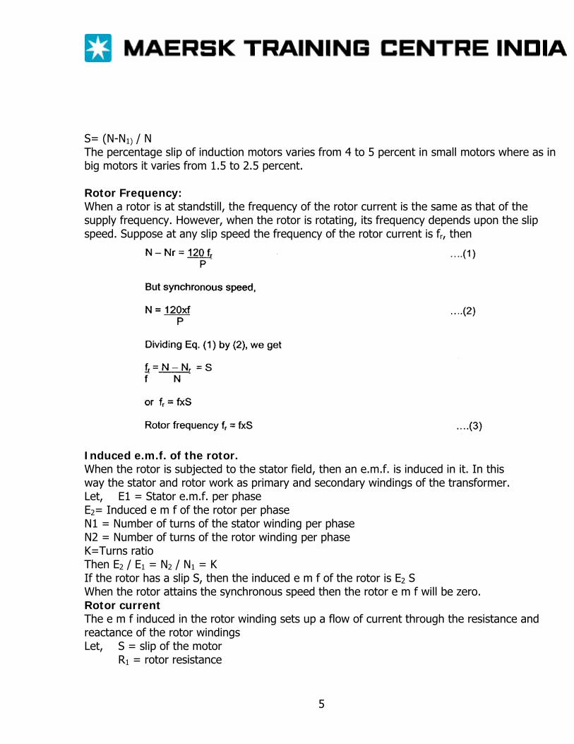
S= (N-N1) / N The percentage slip of induction motors varies from 4 to 5 percent in small motors where as in big motors it varies from 1.5 to 2.5 percent. Rotor Frequency: When a rotor is at standstill, the frequency of the rotor current is the same as that of the supply frequency. However, when the rotor is rotating, its frequency depends upon the slip speed. Suppose at any slip speed the frequency of the rotor current is fr, then
Induced e.m.f. of the rotor. When the rotor is subjected to the stator field, then an e.m.f. is induced in it. In this way the stator and rotor work as primary and secondary windings of the transformer. Let, E1 = Stator e.m.f. per phase E2= Induced e m f of the rotor per phase N1 = Number of turns of the stator winding per phase N2 = Number of turns of the rotor winding per phase K=Turns ratio Then E2 / E1 = N2 / N1 = K If the rotor has a slip S, then the induced e m f of the rotor is E2 S When the rotor attains the synchronous speed then the rotor e m f will be zero. Rotor current The e m f induced in the rotor winding sets up a flow of current through the resistance and reactance of the rotor windings Let, S = slip of the motor
R1 = rotor resistance
5
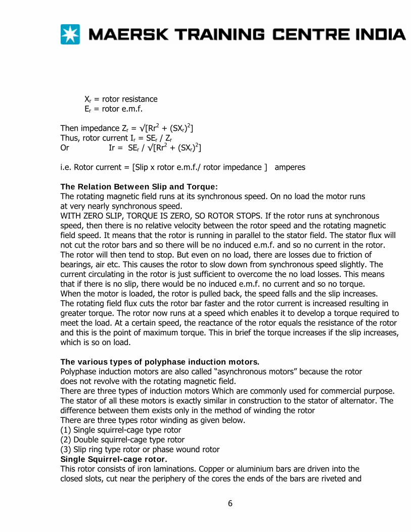
Xr = rotor resistance Er = rotor e.m.f.
Then impedance Zr = √[Rr2 + (SXr)2] Thus, rotor current Ir = SEr / Zr
Or Ir = SEr / √[Rr2 + (SXr)2] i.e. Rotor current = [Slip x rotor e.m.f./ rotor impedance ] amperes The Relation Between Slip and Torque: The rotating magnetic field runs at its synchronous speed. On no load the motor runs at very nearly synchronous speed. WITH ZERO SLIP, TORQUE IS ZERO, SO ROTOR STOPS. If the rotor runs at synchronous speed, then there is no relative velocity between the rotor speed and the rotating magnetic field speed. It means that the rotor is running in parallel to the stator field. The stator flux will not cut the rotor bars and so there will be no induced e.m.f. and so no current in the rotor. The rotor will then tend to stop. But even on no load, there are losses due to friction of bearings, air etc. This causes the rotor to slow down from synchronous speed slightly. The current circulating in the rotor is just sufficient to overcome the no load losses. This means that if there is no slip, there would be no induced e.m.f. no current and so no torque. When the motor is loaded, the rotor is pulled back, the speed falls and the slip increases. The rotating field flux cuts the rotor bar faster and the rotor current is increased resulting in greater torque. The rotor now runs at a speed which enables it to develop a torque required to meet the load. At a certain speed, the reactance of the rotor equals the resistance of the rotor and this is the point of maximum torque. This in brief the torque increases if the slip increases, which is so on load. The various types of polyphase induction motors. Polyphase induction motors are also called “asynchronous motors” because the rotor does not revolve with the rotating magnetic field. There are three types of induction motors Which are commonly used for commercial purpose. The stator of all these motors is exactly similar in construction to the stator of alternator. The difference between them exists only in the method of winding the rotor There are three types rotor winding as given below. (1) Single squirrel-cage type rotor (2) Double squirrel-cage type rotor (3) Slip ring type rotor or phase wound rotor Single Squirrel-cage rotor. This rotor consists of iron laminations. Copper or aluminium bars are driven into the closed slots, cut near the periphery of the cores the ends of the bars are riveted and
6
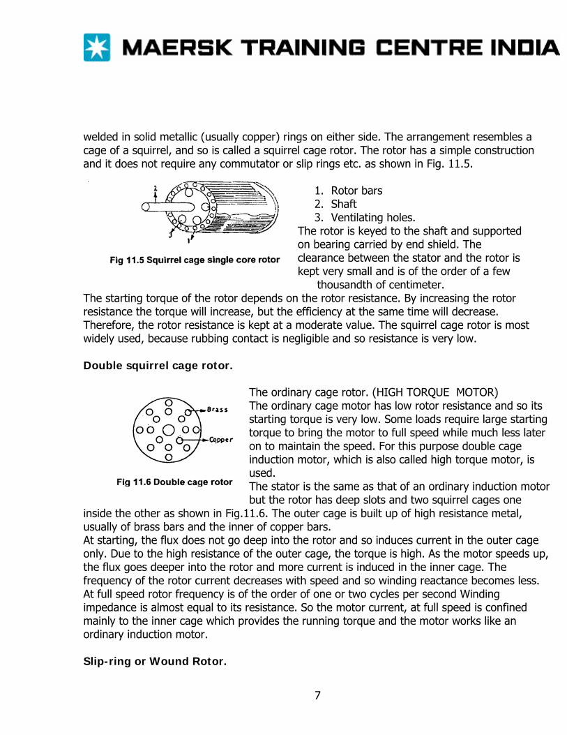
welded in solid metallic (usually copper) rings on either side. The arrangement resembles a cage of a squirrel, and so is called a squirrel cage rotor. The rotor has a simple construction and it does not require any commutator or slip rings etc. as shown in Fig. 11.5.
1. Rotor bars 2. Shaft 3. Ventilating holes.
The rotor is keyed to the shaft and supported on bearing carried by end shield. The clearance between the stator and the rotor is kept very small and is of the order of a few
thousandth of centimeter. The starting torque of the rotor depends on the rotor resistance. By increasing the rotor resistance the torque will increase, but the efficiency at the same time will decrease. Therefore, the rotor resistance is kept at a moderate value. The squirrel cage rotor is most widely used, because rubbing contact is negligible and so resistance is very low. Double squirrel cage rotor.
The ordinary cage rotor. (HIGH TORQUE MOTOR) The ordinary cage motor has low rotor resistance and so its starting torque is very low. Some loads require large starting torque to bring the motor to full speed while much less later on to maintain the speed. For this purpose double cage induction motor, which is also called high torque motor, is used. The stator is the same as that of an ordinary induction motor but the rotor has deep slots and two squirrel cages one
inside the other as shown in Fig.11.6. The outer cage is built up of high resistance metal, usually of brass bars and the inner of copper bars. At starting, the flux does not go deep into the rotor and so induces current in the outer cage only. Due to the high resistance of the outer cage, the torque is high. As the motor speeds up, the flux goes deeper into the rotor and more current is induced in the inner cage. The frequency of the rotor current decreases with speed and so winding reactance becomes less. At full speed rotor frequency is of the order of one or two cycles per second Winding impedance is almost equal to its resistance. So the motor current, at full speed is confined mainly to the inner cage which provides the running torque and the motor works like an ordinary induction motor. Slip-ring or Wound Rotor.
7
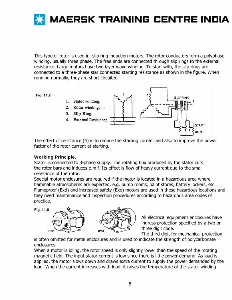
This type of rotor is used in. slip ring induction motors. The rotor conductors form a polyphase winding, usually three phase. The free ends are connected through slip rings to the external resistance. Large motors have two layer wave winding. To start with, the slip rings are connected to a three-phase star connected starting resistance as shown in the figure. When running normally, they are short circuited.
The effect of resistance (4) is to reduce the starting current and also to improve the power factor of the rotor current at starting. Working Principle. Stator is connected to 3-phase supply. The rotating flux produced by the stator cuts the rotor bars and induces e.m.f. Its effect is flow of heavy current due to the small resistance of the rotor. Special motor enclosures are required if the motor is located in a hazardous area where flammable atmospheres are expected, e.g. pump rooms, paint stores, battery lockers, etc. Flameproof (Exd) and increased safety (Exe) motors are used in these hazardous locations and they need maintenance and inspection procedures according to hazardous area codes of practice.
All electrical equipment enclosures have ingress protection specified by a two or three digit code. The third digit for mechanical protection
is often omitted for metal enclosures and is used to indicate the strength of polycarbonate enclosures. When a motor is idling, the rotor speed is only slightly lower than the speed of the rotating magnetic field. The input stator current is low since there is little power demand. As load is applied, the motor slows down and draws extra current to supply the power demanded by the load. When the current increases with load, it raises the temperature of the stator winding
8
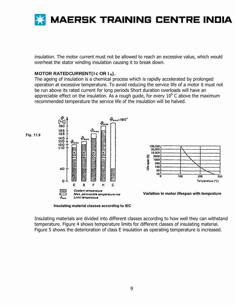
insulation. The motor current must not be allowed to reach an excessive value, which would overheat the stator winding insulation causing it to break down. MOTOR RATEDCURRENT(Ic OR IN). The ageing of insulation is a chemical process which is rapidly accelerated by prolonged operation at excessive temperature. To avoid reducing the service life of a motor it must not be run above its rated current for long periods Short duration overloads will have an appreciable effect on the insulation. As a rough guide, for every 100 C above the maximum recommended temperature the service life of the insulation will be halved.
Insulating materials are divided into different classes according to how well they can withstand temperature. Figure 4 shows temperature limits for different classes of insulating material. Figure 5 shows the deterioration of class E insulation as operating temperature is increased.
9
STARTERS Starters are essentially required for starting motors with a safe value of stator current. Any a.c. motor can be switched on directly but incase of very heavy motors the starting current may be so high that the source cannot supply such a high starting current. Since the starting current of a.c. motors may reach six to seven times of normal running current. Hence the starters are incorporated for starting a.c. motors. There are three types of starters available for starting these motors; 1) Full voltage starter (D.O.L. Starter) 2) Reduced voltage starters. There are two types of reduced voltage starters: -
I. Star / Delta Starter II. Auto transformer starter
3) Soft Starters: - These starters are used normally for starting very large motors where thyristors / IGBT’s are used. Electrical Components 1. Main Contactor 2. Thermal Overload Relay 3. Auxiliary Contactor 4. Plug in relay 5. Timers “ON” Delay
“OFF” Delay Combination
6. Fuses 7 Push Buttons 8 Switches There are various suppliers of electrical switchgear being installed on board ships examples, Terasaki, Telemecanique, Siemens etc The electrical components supplied and fitted by these manufacturers are identified in their circuit diagrams and installation drawings by numbers and letters which will be indicated in the index or in the list of components supplied manufacturers. In following pages the drawings are drawn with standard symbols accepted by IEC.
1
STARTER TYPES: I FULL — VOLTAGE STARTER NON — REVERSING II FULL — VOLTAGE STARTER, REVERSING HI FULL — VOLTAGE STARTER, TWO SPEED IV FULL — VOLTAGE STARTER, LONG TIME V REDUCED VOLTAGE STARTERS VI STAR DELTA VII AUTO TRANSFORMER VIII STARTER, AUTOMATIC START - STOP CONTROL 6 CONTACTOR (FOR 0/C RELAY - SHORT CIRCUITING) 19 TIME DELAY RELAY (CONTROLS CONTACTOR 6) 42 CONTACTOR (OR RUNNING) 51 THERMAL OVERCURRENT RELAY 52 MOLDED CASE CIRCUIT BREAKER 88 CONTACTOR 89 MOLDED CASE SWITCH 6-1 CONTACTOR (FOR AUTO TRANSFORMER Y - CONNECTION 6-2 CONTCTOR (FOR STARTING) 88F CONTACTOR FOR FORWARD OPERATION 88R CONTACTOR FOR REVERSE OPERATION A AMMTER Atr AUTO TRANSEORMER BS PUSH BUTTPN SWITCH FC FUSE- CONTROL CIRCUIT FL FUSE L RUNNING LIGHT WITH TRANSFORMER LF RUNNING LIGHTS FWD LH HIGH SPEED - RUNNING LIGHTS LL LOW SPEED - RUNNING LIGHTS LR RUNNING LIGHTS REVERSE M ELECTRIC MOTOR, SINGLE WINDING, 2- SPEED RC REMOTE CONTROL SWITCH BOX.
2
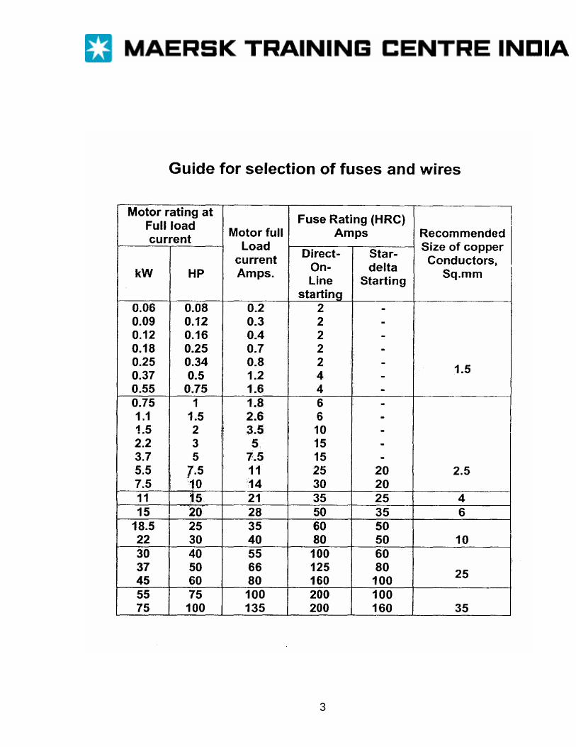
3
BATTERIES The ability of a battery to deliver electrical power instantly, together with its convenience, has enabled the battery to become widely used as an emergency power source and to power portable equipment. The basic single unit in a battery is referred to as a cell’. Cells are connected in a series arrangement to form the battery. The e.m.f of a cell is quite small, typically 1-3V. The series connection of cells in a battery enables larger and more useful voltages to be made available. A cell produces electrical current by chemical re-action. It consists of two electrodes (anode and cathode) of different materials which are connected by an electrolyte; a chemical which reacts suitably with both electrodes. An electrochemical series shows the relative positions of possible electrode materials. Potassium Anodic: Sodium More corrosive end of table Lithium Magnesium Zinc Lead Hydrogen Copper Mercury Silver Carbon Sulphur Cathodic: Oxygen More noble end of table Any two substances in the list will form a couple in conjunctions with a suitable electrolyte. The further apart the couple is in the list, the greater the e.m.f developed. In 1800, Professor Volta produced the first battery using a zinc-silver couple with a brine electrolyte, which developed an e.m.f of 1 .4V. The electrochemical series shown is by no means a complete list of possible substances but the series would seem to indicate the possibility of an enormous number of cell couples. In reality, the difficulty of combining suitable electrode materials with an electrolyte that will give stable chemical action with stable operating voltage and long life limits the number of practical cells that are possible.
1
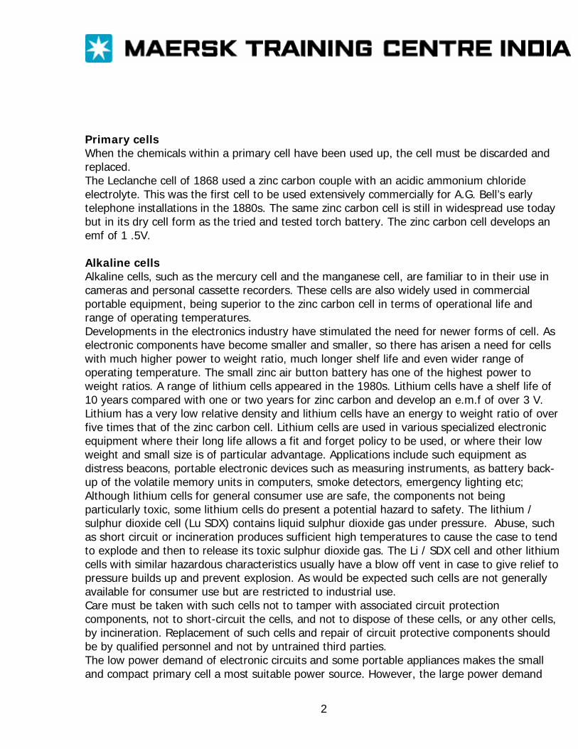
Primary cells When the chemicals within a primary cell have been used up, the cell must be discarded and replaced. The Leclanche cell of 1868 used a zinc carbon couple with an acidic ammonium chloride electrolyte. This was the first cell to be used extensively commercially for A.G. Bell’s early telephone installations in the 1880s. The same zinc carbon cell is still in widespread use today but in its dry cell form as the tried and tested torch battery. The zinc carbon cell develops an emf of 1 .5V. Alkaline cells Alkaline cells, such as the mercury cell and the manganese cell, are familiar to in their use in cameras and personal cassette recorders. These cells are also widely used in commercial portable equipment, being superior to the zinc carbon cell in terms of operational life and range of operating temperatures. Developments in the electronics industry have stimulated the need for newer forms of cell. As electronic components have become smaller and smaller, so there has arisen a need for cells with much higher power to weight ratio, much longer shelf life and even wider range of operating temperature. The small zinc air button battery has one of the highest power to weight ratios. A range of lithium cells appeared in the 1980s. Lithium cells have a shelf life of 10 years compared with one or two years for zinc carbon and develop an e.m.f of over 3 V. Lithium has a very low relative density and lithium cells have an energy to weight ratio of over five times that of the zinc carbon cell. Lithium cells are used in various specialized electronic equipment where their long life allows a fit and forget policy to be used, or where their low weight and small size is of particular advantage. Applications include such equipment as distress beacons, portable electronic devices such as measuring instruments, as battery back-up of the volatile memory units in computers, smoke detectors, emergency lighting etc; Although lithium cells for general consumer use are safe, the components not being particularly toxic, some lithium cells do present a potential hazard to safety. The lithium / sulphur dioxide cell (Lu SDX) contains liquid sulphur dioxide gas under pressure. Abuse, such as short circuit or incineration produces sufficient high temperatures to cause the case to tend to explode and then to release its toxic sulphur dioxide gas. The Li / SDX cell and other lithium cells with similar hazardous characteristics usually have a blow off vent in case to give relief to pressure builds up and prevent explosion. As would be expected such cells are not generally available for consumer use but are restricted to industrial use. Care must be taken with such cells not to tamper with associated circuit protection components, not to short-circuit the cells, and not to dispose of these cells, or any other cells, by incineration. Replacement of such cells and repair of circuit protective components should be by qualified personnel and not by untrained third parties. The low power demand of electronic circuits and some portable appliances makes the small and compact primary cell a most suitable power source. However, the large power demand
2
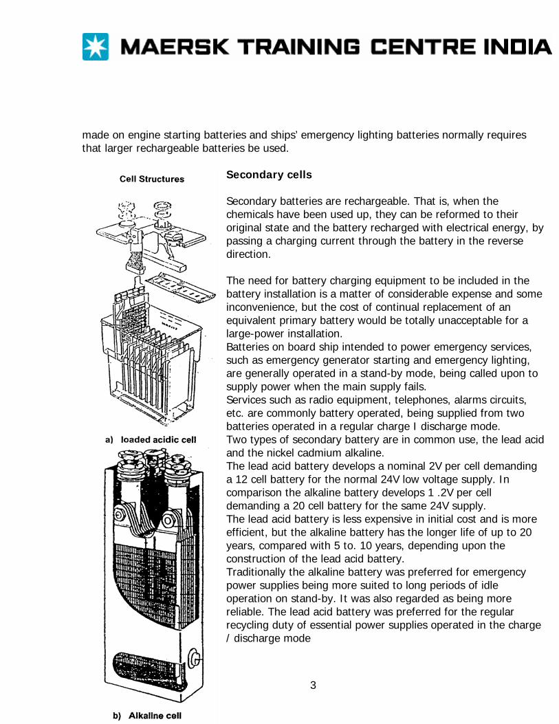
3
made on engine starting batteries and ships’ emergency lighting batteries normally requires that larger rechargeable batteries be used.
Secondary cells Secondary batteries are rechargeable. That is, when the chemicals have been used up, they can be reformed to their original state and the battery recharged with electrical energy, by passing a charging current through the battery in the reverse direction. The need for battery charging equipment to be included in the battery installation is a matter of considerable expense and some inconvenience, but the cost of continual replacement of an equivalent primary battery would be totally unacceptable for a large-power installation. Batteries on board ship intended to power emergency services, such as emergency generator starting and emergency lighting, are generally operated in a stand-by mode, being called upon to supply power when the main supply fails. Services such as radio equipment, telephones, alarms circuits, etc. are commonly battery operated, being supplied from two batteries operated in a regular charge I discharge mode. Two types of secondary battery are in common use, the lead acid and the nickel cadmium alkaline. The lead acid battery develops a nominal 2V per cell demanding a 12 cell battery for the normal 24V low voltage supply. In comparison the alkaline battery develops 1 .2V per cell demanding a 20 cell battery for the same 24V supply. The lead acid battery is less expensive in initial cost and is more efficient, but the alkaline battery has the longer life of up to 20 years, compared with 5 to. 10 years, depending upon the construction of the lead acid battery. Traditionally the alkaline battery was preferred for emergency power supplies being more suited to long periods of idle operation on stand-by. It was also regarded as being more reliable. The lead acid battery was preferred for the regular recycling duty of essential power supplies operated in the charge / discharge mode
However many current installations have lead acid batteries specially designed for the stand by duty of emergency power loads and emergency generator starting. The electrolyte of the lead acid cell is a dilute solution of sulphuric acid; that of the alkaline cell a solution of potassium, hydroxide both aqueous solutions Both types of cell ‘gas’ when on charge, the alkaline line cell more or less continuously and the lead acid cell when nearing the top of the charge. Hydrogen and oxygen gases are evolved due to the chemical breakdown of the water content of the electrolyte. The cells are vented to allow gases to escape and prevent internal pressure build up. Gassing presents several problems. Hydrogen is a highly dangerous explosive gas and the evolved gases carry with them a mist of corrosive acid or alkaline electrolyte. Large batteries (above 2 kW) must be installed in specially prepared rooms or lockers, well ventilated to remove the explosive hydrogen gas, illuminated by suitable explosion protected luminaries and steel work painted to resist corrosion. In addition personnel must exercise care not to cause sparks or produce naked flames when inspecting batteries. Notices to this effect must be displayed. The evolution of gas, together with evaporation causes a significant water loss from the electrolyte and this must be made good by topping up with distilled water as necessary. Acid batteries and alkaline batteries must not be located in the same room, to prevent danger of battery damage caused by contamination of the alkaline battery by acid. Battery maintenance Battery maintenance is substantially the same for both types of battery. Cell tops must be kept clean and dry, vents clear and free of deposits, terminal connections tight, free of corrosion and coated with petroleum jelly to prevent corrosion. Electrolyte levels should be checked and topped up with distilled water to cover the plates. Safety precautions necessary during these procedures include wearing suitable protective clothing (rubber apron, rubber gloves and eye goggles), ensuring no sources of naked light are taken into the metallic jugs and other utensils to prevent spark and short circuits. In addition suitable first aid treatments should be available. Sulphuric acid splashes on the skin should be washed off with fresh water and treated with a saline solution (one tablespoon of salt to half a litre of water). Potassium hydroxide splashes should again be washed off with fresh water but treated with boracic powder or a boracic acid solution (one teaspoon of boracic powder to half a litre of water). Splashes in the eye are particularly dangerous. Liberal splashing of water in the eye, followed by washing in the aforementioned neutralizing solutions is the immediate treatment. Rapid action and large quantities of water are essential, followed by seeking qualified medical attention. The state of charge of a cell can be checked by measuring its terminal voltage while supplying load current; the terminal voltage of an idle cell is likely to be high giving a false indication of a fully charged cell. The terminal voltage of a fully charged alkaline cell is about 1 2V falling to 1 09V
4
when fully discharged. The terminal voltage of a fully charged acid cell is about 2.0V falling to 1 75V when fully discharged If voltage readings are taken while battery is on charge the end of charge is indicated when the terminal voltage of an alkaline cell levels out at about 1.7V. For acid cells the end of charge is indicated at about 2.6V measured while on charge Maintenance procedures include measuring the relative density (or specific gravity) of the electrolyte. In the case of lead acid batteries, the relative density is a valuable indication of the state of charge of a cell, varying from 1.275-1.285 (specific gravity 1275-1285) for fully charged cell, to about 1.1 (specific gravity 1100) when fully discharged. The relative density readings vary with temperature and temperature corrections must be made to arrive at a temperature corrections must be made to arrive at a meaningful value. The above values are quoted for an ideal electrolyte temperature of 15° C. Actual readings should be corrected by adding 0.007 for each 10°C above 15°C and subtracting 0.007 for each 10°C below 15° C. In the case of alkaline batteries, the relative density does not change and gives no indication of the state of charge of the cell. Nevertheless, the relative density should be measured regularly falls. A new cell will have a relative density gradually falls. A new cell will have a relative density of about 1.190. When this fails to about 1.145, indicating that chemical deterioration has occurred, the electrolyte should be renewed or the battery replaced. This may be necessary only after 5 to 10 years depending upon the duty cycle for which the battery is employed. Manufacturer’s recommendations should be followed for renewing electrolyte. The relative density of the electrolyte of a cell is measured using a hydrometer of the syringe type (Fig 13.1). Batteries should be charged from suitable charging equipment according to manufacturers’ instructions. The battery capacity is rated in terms of its discharge current at the 10 hours rate. A 25OAhrs battery can supply 25A for 10 hours. Charging current can also be based upon the 10 hours rate but frequently is based upon shorter time rates such as 7 hours or 6 hours. Lead acid cells should be charged until gassing freely, and charging should then continue for a further period until the charging voltage per cell levels out at about 2.6V. Overcharging causes overheating, distortion of cell plates and consequent dislodging of plate active materials. Lead acid cells suffer self-discharge; if the battery is left idle an internal discharge would slowly dissipate the charged energy. A fully charged lead acid cell must be maintained on a trickle charge, a low rate charge, to make up the loss due to ‘self discharge’. Alkaline cells should be charged at the recommended rate until gassing freely and the charging voltage per cell rises to about 1 .7V. Charging should continue for a further two or three hours. Alkaline cells are able to retain their full charge for a considerable period and do not suffer self- discharge except at high temperatures. Periodically, alkaline batteries should be. given a short (two to three hours) refresher charge. Alkaline cells are well suited to the float charge mode of operation of stand-by power batteries. Here the battery is connected across the load
5
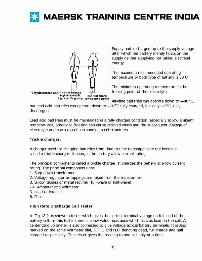
Supply and is charged up to the supply voltage after which the battery merely floats on the supply neither supplying nor taking electrical energy. -, The maximum recommended operating temperature of both type of battery is 50 C. The minimum operating temperature is the freezing point of the electrolyte Alkaline batteries can operate down to —40° C
but lead acid batteries can operate down to —320C fully charged, but only —9°C, fully discharged. Lead acid batteries must be maintained in a fully charged condition, especially at low ambient temperatures, otherwise freezing can cause cracked cases and the subsequent leakage of electrolyte and corrosion of surrounding steel structures. Trickle charger: A charger used for charging batteries from time to time to compensate the losses is called a trickle charger. It charges the battery a low current rating. The principal components called a trickle charger. It charges the battery at a low current rating. The principal components are: 1. Step down transformer. 2. Voltage regulator or tappings are taken from the transformer. 3. Silicon diodes or metal rectifier (full-wave or half-wave) - 4. Ammeter and voltmeter. 5. Load resistance. 6. Fuse. High Rate Discharge Cell Tester In Fig.13.2. is shown a tester which gives the correct terminal voltage on full load of the battery cell. In this tester there is a low value resistance which acts as load on the cell. A center zero voltmeter is also connected to give voltage across battery terminals. It is also marked on the same voltmeter dial, D.F.C. and H.C. denoting dead, full charge and half charged respectively. This tester gives the reading to one cell only at a time.
6
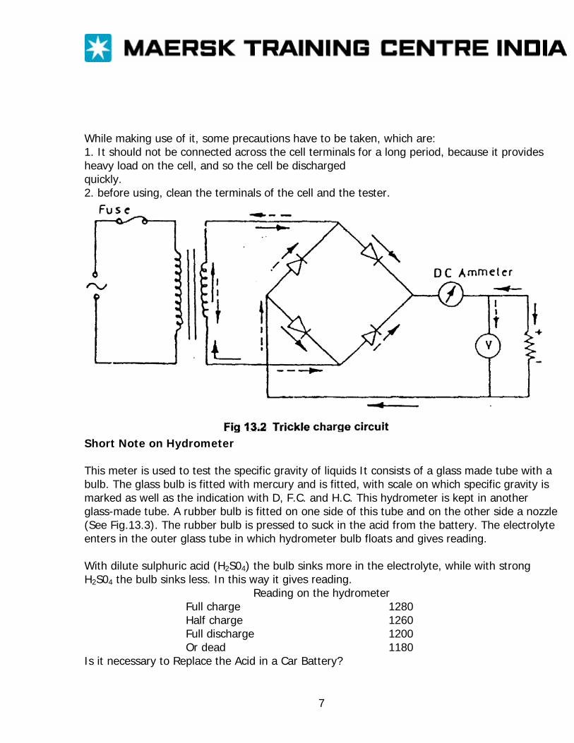
While making use of it, some precautions have to be taken, which are: 1. It should not be connected across the cell terminals for a long period, because it provides heavy load on the cell, and so the cell be discharged quickly. 2. before using, clean the terminals of the cell and the tester.
Short Note on Hydrometer This meter is used to test the specific gravity of liquids It consists of a glass made tube with a bulb. The glass bulb is fitted with mercury and is fitted, with scale on which specific gravity is marked as well as the indication with D, F.C. and H.C. This hydrometer is kept in another glass-made tube. A rubber bulb is fitted on one side of this tube and on the other side a nozzle (See Fig.13.3). The rubber bulb is pressed to suck in the acid from the battery. The electrolyte enters in the outer glass tube in which hydrometer bulb floats and gives reading. With dilute sulphuric acid (H2S04) the bulb sinks more in the electrolyte, while with strong H2S04 the bulb sinks less. In this way it gives reading.
Reading on the hydrometer Full charge 1280 Half charge 1260 Full discharge 1200 Or dead 1180
Is it necessary to Replace the Acid in a Car Battery?
7
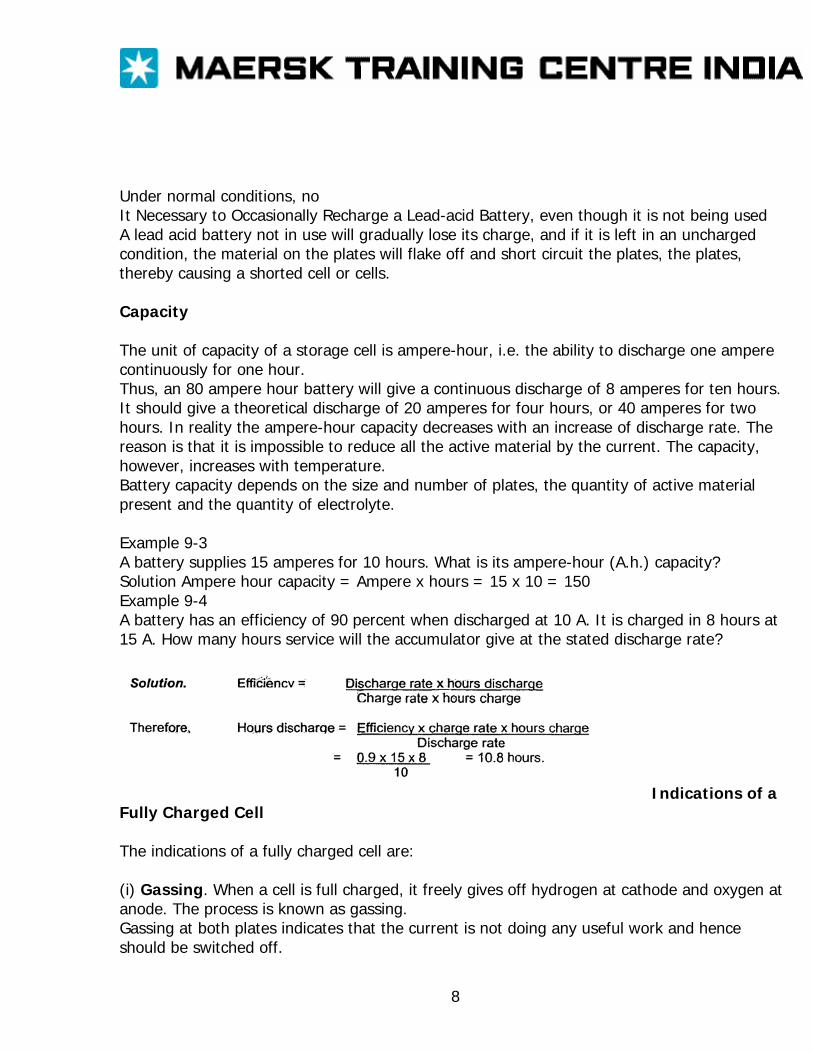
Under normal conditions, no It Necessary to Occasionally Recharge a Lead-acid Battery, even though it is not being used A lead acid battery not in use will gradually lose its charge, and if it is left in an uncharged condition, the material on the plates will flake off and short circuit the plates, the plates, thereby causing a shorted cell or cells. Capacity The unit of capacity of a storage cell is ampere-hour, i.e. the ability to discharge one ampere continuously for one hour. Thus, an 80 ampere hour battery will give a continuous discharge of 8 amperes for ten hours. It should give a theoretical discharge of 20 amperes for four hours, or 40 amperes for two hours. In reality the ampere-hour capacity decreases with an increase of discharge rate. The reason is that it is impossible to reduce all the active material by the current. The capacity, however, increases with temperature. Battery capacity depends on the size and number of plates, the quantity of active material present and the quantity of electrolyte. Example 9-3 A battery supplies 15 amperes for 10 hours. What is its ampere-hour (A.h.) capacity? Solution Ampere hour capacity = Ampere x hours = 15 x 10 = 150 Example 9-4 A battery has an efficiency of 90 percent when discharged at 10 A. It is charged in 8 hours at 15 A. How many hours service will the accumulator give at the stated discharge rate?
Indications of a
Fully Charged Cell The indications of a fully charged cell are: (i) Gassing. When a cell is full charged, it freely gives off hydrogen at cathode and oxygen at anode. The process is known as gassing. Gassing at both plates indicates that the current is not doing any useful work and hence should be switched off.
8
(ii) Voltage. When the cell is fully charged the voltage ceases to rise. The voltage of a fully charged cell is variable depending upon the rate of charging, the temperature and specific gravity of the electrolyte etc. The approximate value of e.m.f. is 2.1 volt. (iii) Specific gravity of electrolyte. During discharging, the density of electrolyte decreases due to formation of water while it increases during charging due to the absorption of water. When the cell is fully charged its density is 1.21. and when discharged up to 1.8 V it is 1.18. Specific gravity can be measured with a suitable hydrometer. (iv) Colour. On full charge, the Colour of the Positive plates is deep chocolate brown and for negative plate it is slate gray. Suiphation: Lead peroxide (Pb02) and lead (Pb) loss the property of reconversion if the cell is not fully charged and is also not charged from time to time. Lead sulphate (PbSO4) gets deposited on the plate and it is then said to be sulphated. The effect is to increase the internal resistance of the cell and to reduce its efficiency and capacity. Sealed batteries or sealed gas recombination cells: Sealed batteries, or sealed gas recombination cells as they are more properly called, are commonly located within items of equipment. Vented cells, with their emission of explosive gases and corrosive mists, must be located in a ‘safe’ central battery room. Vented cells contain free liquid (and spillable) corrosive electrolyte. Water loss occurs demanding topping up. Sealed cells, both acid and alkaline types, are specially designed and manufactured so that gassing does not occur in normal regular service. The cells can thus be sealed without danger of pressure build-up, require no topping up, demand very little maintenance and are safe for installation at sites out of bounds to the vented cells, such as within office equipment and electronic equipment. Many items of equipment such as navigation lights, fire detection and alarm systems, engine room control consoles, etc. now have their own emergency battery located within their own cabinet and are self contained, rather then having to rely upon a remote centralized emergency power supply unit. In case of fault and abuse the cells have a blow-off vent to relieve any pressure build up by possible gassing. Standby and Uninterrupted Power Supply System
9
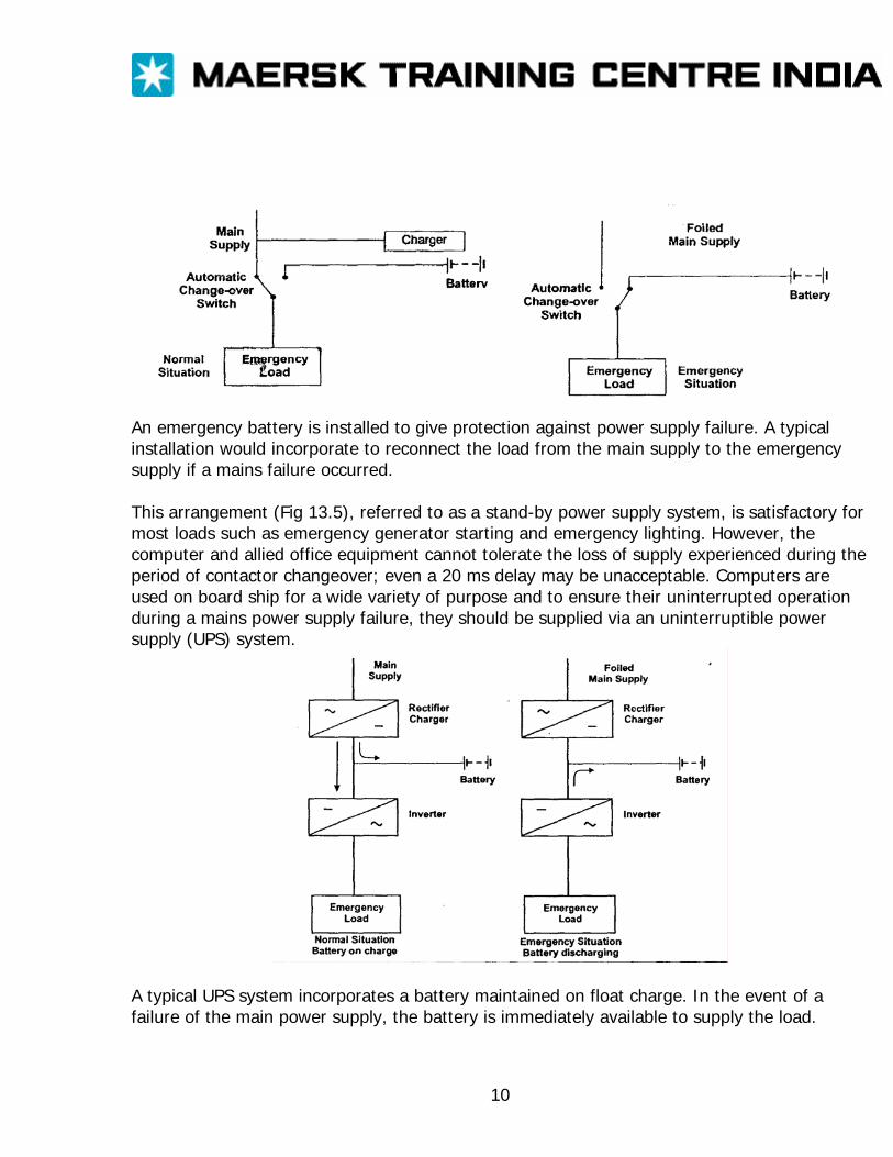
An emergency battery is installed to give protection against power supply failure. A typical installation would incorporate to reconnect the load from the main supply to the emergency supply if a mains failure occurred. This arrangement (Fig 13.5), referred to as a stand-by power supply system, is satisfactory for most loads such as emergency generator starting and emergency lighting. However, the computer and allied office equipment cannot tolerate the loss of supply experienced during the period of contactor changeover; even a 20 ms delay may be unacceptable. Computers are used on board ship for a wide variety of purpose and to ensure their uninterrupted operation during a mains power supply failure, they should be supplied via an uninterruptible power supply (UPS) system.
A typical UPS system incorporates a battery maintained on float charge. In the event of a failure of the main power supply, the battery is immediately available to supply the load.
10

The system (Fig 13.6) also incorporates circuits to filter out mains disturbances such as transients and spikes, which can corrupt computer operation. Units rated up to 300 kVA are available but a typical shipboard unit would be rated about 1.5 kVA.
11
MAINTENANCE Maintenance is applied to equipment in an attempt to extend its useful life; to ensure that it remains in a safe and serviceable condition. To many people, maintenance is regarded as being merely repairs or replacement of equipment that has suffered breakdown, indeed, such an approach is still widely applied today. In 1969-1970 the cost and dangers involved with breakdown led to in-depth studies of the practices used. These studies were government sponsored and the results were published by HMSO. The report suggested that maintenance in general was in urgent need of planning and control to improve utilization of labor, to improve care of valuable physical assets and to reduce the national financial loss resulting from plant down time and loss of services. The demand for improvements in maintenance was made under the name of terotechnology. In general, maintenance philosophy can be classified under the three headings, breakdown or failure maintenance, periodic maintenance and condition maintenance. Breakdown or failure maintenance This is applied because of breakdown, of breakdown of equipment or its inability to meet its operational requirements. The equipment is left untouched until failure occurs. At this time the equipment must be repaired or replaced and any other procedures carried out. On board ship if failure occurs the defect is brought to the attention of the chief engineer who then decides on the course of action to be taken. There are disadvantages with failure maintenance 1. A serious breakdown of equipment may cause sufficient down time to put the ship out of commission until it is repaired. 2 if several break down occur at about the same time the available manpower onboard may not be able to cope adequately resulting in delays 3. Some items of equipment may need the specialist services of the manufacturer to carry out repairs and this may cause further delays. Despite these disadvantages, it is believed that failure maintenance is still widely applied, the responsibility for implementing maintenance being given to ship’s staff, who see failure maintenance as a simple and logical practice. Planned maintenance A degree of planning is required in the operation of failure maintenance in organization and for stocking spare parts and tools. However, the term-planned maintenance is only applied to maintenance schemes where the application of maintenance and the practices involved are pre-planned and rigorously applied.
1
The object of planned maintenance is to prevent failure and breakdown of equipment and so avoid the consequent disadvantages that are incurred. However, breakdown and failure can still occur and emergency failure maintenance may still have to be applied. Two systems of planned maintenance are in common use; periodic maintenance and planned maintenance. Periodic maintenance Periodic maintenance is the application of specified routine maintenance after a predetermined calendar period has elapsed, or after a number of running hours for the equipment have been recorded. A special case arises for equipment in which no inspection or repair is possible. For such equipment life maintenance is applied. Life maintenance means that no maintenance is carried out during the unit’s predetermined useful life. At the end of this period, the unit is replaced (unless, of course, breakdown occurs and emergency unscheduled replacement maintenance applied). Advantages of periodic maintenance 1. There are fewer breakdowns and the consequent reduced down time, produce much higher levels of operating efficiency. 2. Maintenance is carried out at times most favorable to the operation of plant. 3. There is more effective utilization of labor because maintenance is carried out at times favorable to the ship’s staff. 4. Replacement equipment can be ordered in advance at opportune times. 5. Equipment is maintained in a safe condition and with reduced possible dangers. 6. When the specialist services of the manufacturer are required, they can be arranged for opportune times 7. Life maintenance of short life components arranged at scheduled times. The operation of a periodic maintenance system requires the setting up of specially designed wall charts and documentation and is controlled usually by the Chief Engineer. Regular planning meetings (weekly) where decisions on the work to be done are a feature of the system. Condition maintenance The concept of condition maintenance is altogether different from the two categories of maintenance already described. Condition maintenance has been developed to avoid routine interference with equipment that is performing perfectly satisfactorily The system is designed
2
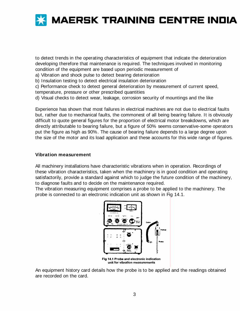
to detect trends in the operating characteristics of equipment that indicate the deterioration developing therefore that maintenance is required. The techniques involved in monitoring condition of the equipment are based upon periodic measurement of a) Vibration and shock pulse to detect bearing deterioration b) Insulation testing to detect electrical insulation deterioration c) Performance check to detect general deterioration by measurement of current speed, temperature, pressure or other prescribed quantities d) Visual checks to detect wear, leakage, corrosion security of mountings and the like Experience has shown that most failures in electrical machines are not due to electrical faults but, rather due to mechanical faults, the commonest of all being bearing failure. It is obviously difficult to quote general figures for the proportion of electrical motor breakdowns, which are directly attributable to bearing failure, but a figure of 50% seems conservative-some operators put the figure as high as 90%. The cause of bearing failure depends to a large degree upon the size of the motor and its load application and these accounts for this wide range of figures. Vibration measurement All machinery installations have characteristic vibrations when in operation. Recordings of these vibration characteristics, taken when the machinery is in good condition and operating satisfactorily, provide a standard against which to judge the future condition of the machinery, to diagnose faults and to decide on the maintenance required. The vibration measuring equipment comprises a probe to be applied to the machinery. The probe is connected to an electronic indication unit as shown in Fig 14.1.
An equipment history card details how the probe is to be applied and the readings obtained are recorded on the card.
3
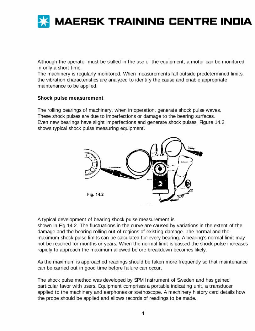
Although the operator must be skilled in the use of the equipment, a motor can be monitored in only a short time. The machinery is regularly monitored. When measurements fall outside predetermined limits, the vibration characteristics are analyzed to identify the cause and enable appropriate maintenance to be applied. Shock pulse measurement The rolling bearings of machinery, when in operation, generate shock pulse waves. These shock pulses are due to imperfections or damage to the bearing surfaces. Even new bearings have slight imperfections and generate shock pulses. Figure 14.2 shows typical shock pulse measuring equipment.
A typical development of bearing shock pulse measurement is shown in Fig 14.2. The fluctuations in the curve are caused by variations in the extent of the damage and the bearing rolling out of regions of existing damage. The normal and the maximum shock pulse limits can be calculated for every bearing. A bearing’s normal limit may not be reached for months or years. When the normal limit is passed the shock pulse increases rapidly to approach the maximum allowed before breakdown becomes likely. As the maximum is approached readings should be taken more frequently so that maintenance can be carried out in good time before failure can occur. The shock pulse method was developed by SPM Instrument of Sweden and has gained particular favor with users. Equipment comprises a portable indicating unit, a transducer applied to the machinery and earphones or stethoscope. A machinery history card details how the probe should be applied and allows records of readings to be made.
4
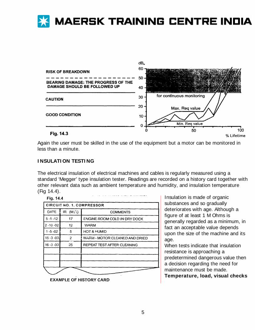
Again the user must be skilled in the use of the equipment but a motor can be monitored in less than a minute. INSULATION TESTING The electrical insulation of electrical machines and cables is regularly measured using a standard ‘Megger’ type insulation tester. Readings are recorded on a history card together with other relevant data such as ambient temperature and humidity, and insulation temperature (Fig 14.4).
Insulation is made of organic substances and so gradually deteriorates with age. Although a figure of at least 1 M Ohms is generally regarded as a minimum, in fact an acceptable value depends upon the size of the machine and its age. When tests indicate that insulation resistance is approaching a predetermined dangerous value then a decision regarding the need for maintenance must be made. Temperature, load, visual checks
5

Standard checks of temperature, load current and a visual check of cleanliness, security damage, corrosion and the like can be quickly carried out and give valuable indications of impending trouble and the need for action. Attempting to measure temperature with the bare hand on equipment is most unreliable. A thermometer should be used. the bulb covered with wadding and attached in contact with the equipment with a suitable compound such as Plasticine. Many portable electronic thermometers are now available with suitable probes for such application. The readings should be compared with the temperature rating of the equipment and also used to estimate the temperature rise of the equipment above ambient temperature. A method of temperature measurement using simple stick on tape devices has gained favor in some quarters. The tape changes colour as temperature changes-a danger signal being given when the tape change to black. High temperature can be caused by poor ventilation, surface dirt which acts as an insulant, overload, High cooling air temperature, or faults within the equipment. Readings of load current of motors and other equipment can be measured using a clamp-on ammeter. The readings should be compared with the rated current as indicated on the equipment rating plate. High load current will cause overheating of equipment and the consequent danger of electrical insulation failure. The cause must be investigated-it may be due to overload, supply voltage and frequency departing from their rated values, or other faults. Whatever the cause, the condition must be rectified above damage arises. A correctly operated maintenance scheme will incorporate and integrate all the type and aspects of maintenance mentioned. Despite all correctly applied maintenance procedures, unscheduled equipment failure will inevitably occur and emergency action will have to be taken. The maintenance scheme must be flexible enough to handle such emergency situations. The mechanics of operating a maintenance system may well be perfectly understood and carried out by the maintenance team. However, the continuing benefits of the system depend entirely upon the good offices of the team and their outlook on their tasks. The system must be looked on as a continually developing unit and improvements made as and when required.
6
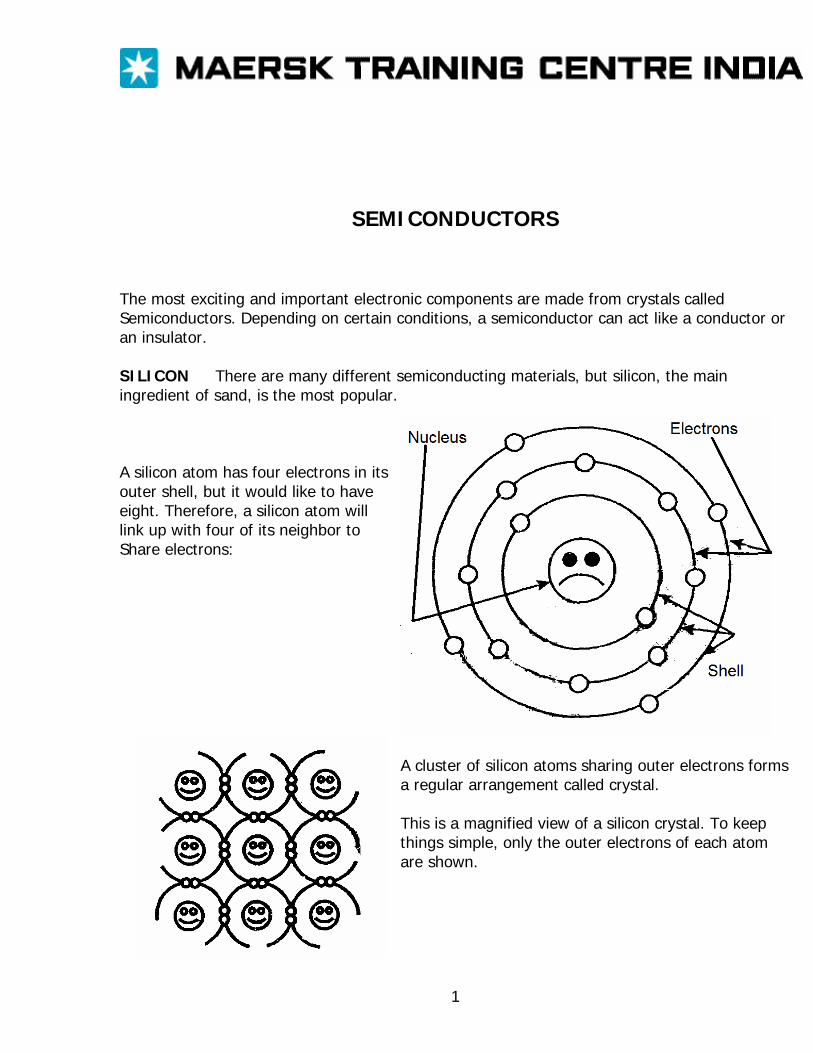
SEMICONDUCTORS
The most exciting and important electronic components are made from crystals called Semiconductors. Depending on certain conditions, a semiconductor can act like a conductor or an insulator. SILICON There are many different semiconducting materials, but silicon, the main ingredient of sand, is the most popular.
A silicon atom has four electrons in its outer shell, but it would like to have eight. Therefore, a silicon atom will link up with four of its neighbor to Share electrons:
A cluster of silicon atoms sharing outer electrons forms a regular arrangement called crystal. This is a magnified view of a silicon crystal. To keep things simple, only the outer electrons of each atom are shown.
1
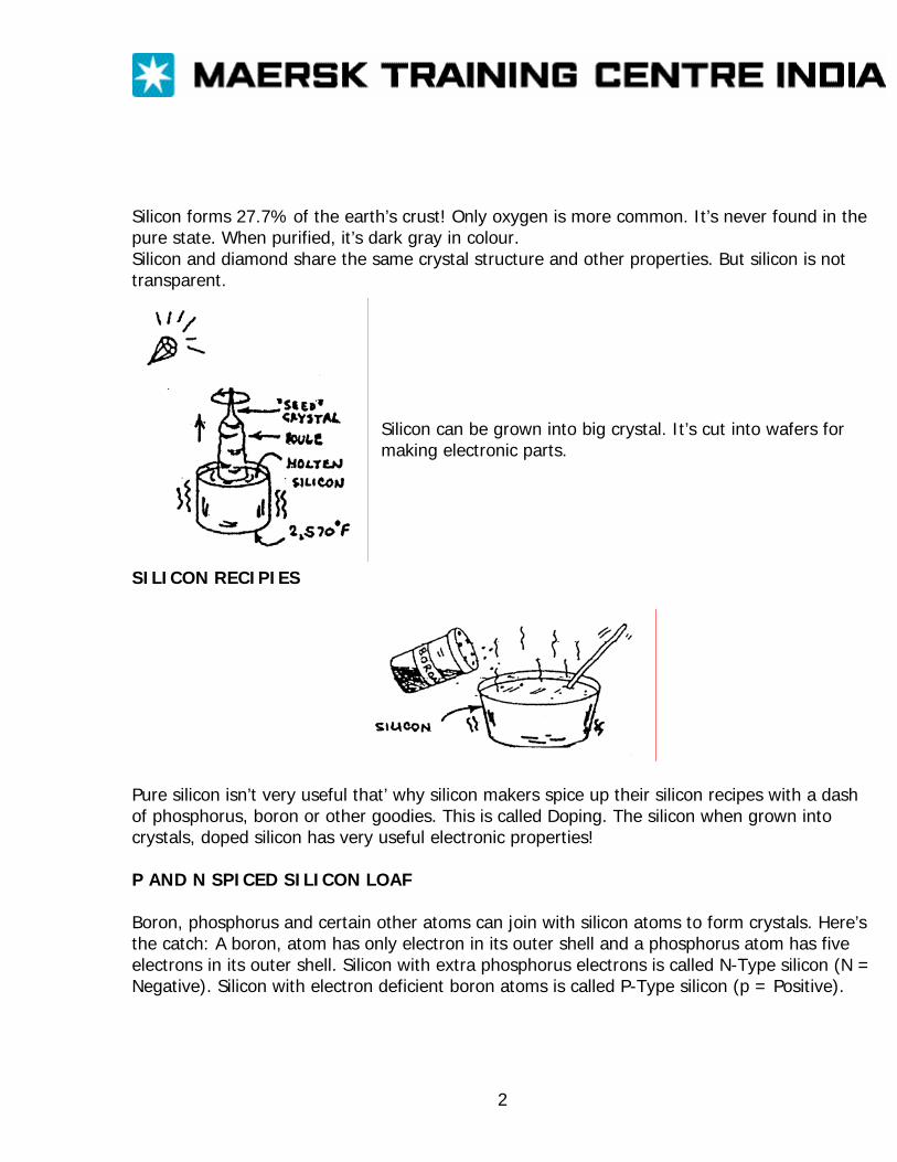
Silicon forms 27.7% of the earth’s crust! Only oxygen is more common. It’s never found in the pure state. When purified, it’s dark gray in colour. Silicon and diamond share the same crystal structure and other properties. But silicon is not transparent.
Silicon can be grown into big crystal. It’s cut into wafers for making electronic parts.
SILICON RECIPIES
Pure silicon isn’t very useful that’ why silicon makers spice up their silicon recipes with a dash of phosphorus, boron or other goodies. This is called Doping. The silicon when grown into crystals, doped silicon has very useful electronic properties! P AND N SPICED SILICON LOAF Boron, phosphorus and certain other atoms can join with silicon atoms to form crystals. Here’s the catch: A boron, atom has only electron in its outer shell and a phosphorus atom has five electrons in its outer shell. Silicon with extra phosphorus electrons is called N-Type silicon (N = Negative). Silicon with electron deficient boron atoms is called P-Type silicon (p = Positive).
2
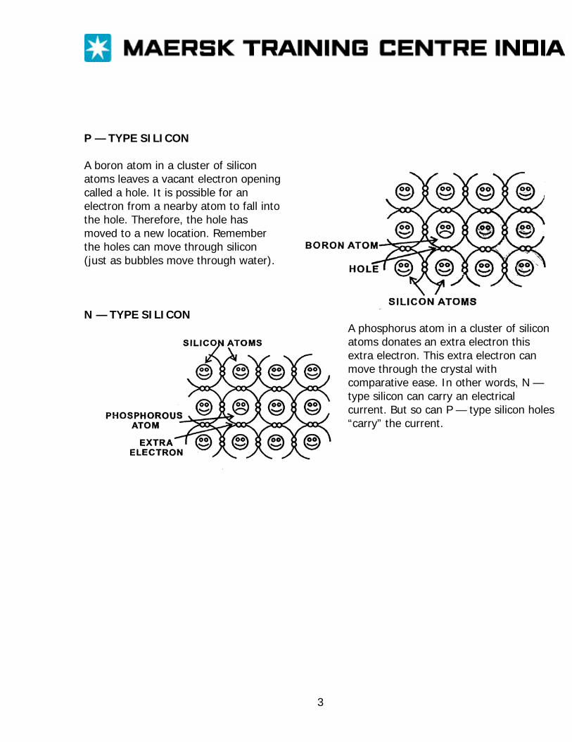
P — TYPE SILICON A boron atom in a cluster of silicon atoms leaves a vacant electron opening called a hole. It is possible for an electron from a nearby atom to fall into the hole. Therefore, the hole has moved to a new location. Remember the holes can move through silicon (just as bubbles move through water).
N — TYPE SILICON
A phosphorus atom in a cluster of silicon atoms donates an extra electron this extra electron. This extra electron can move through the crystal with comparative ease. In other words, N — type silicon can carry an electrical current. But so can P — type silicon holes “carry” the current.
3
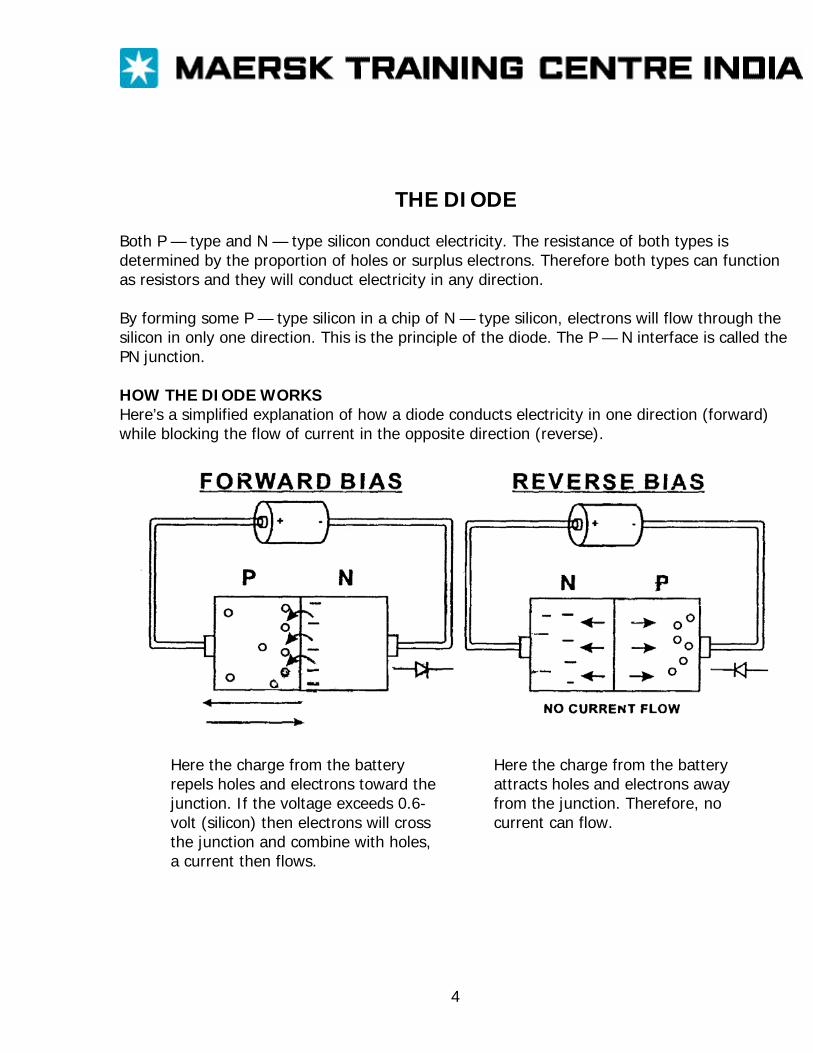
THE DIODE Both P — type and N — type silicon conduct electricity. The resistance of both types is determined by the proportion of holes or surplus electrons. Therefore both types can function as resistors and they will conduct electricity in any direction. By forming some P — type silicon in a chip of N — type silicon, electrons will flow through the silicon in only one direction. This is the principle of the diode. The P — N interface is called the PN junction. HOW THE DIODE WORKS Here’s a simplified explanation of how a diode conducts electricity in one direction (forward) while blocking the flow of current in the opposite direction (reverse).
Here the charge from the battery repels holes and electrons toward the junction. If the voltage exceeds 0.6- volt (silicon) then electrons will cross the junction and combine with holes, a current then flows.
Here the charge from the battery attracts holes and electrons away from the junction. Therefore, no current can flow.
4
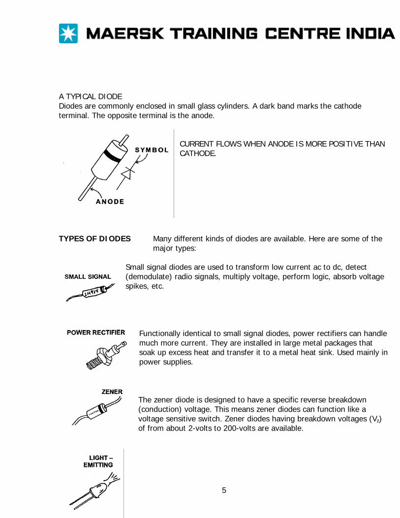
A TYPICAL DIODE Diodes are commonly enclosed in small glass cylinders. A dark band marks the cathode terminal. The opposite terminal is the anode.
CURRENT FLOWS WHEN ANODE IS MORE POSITIVE THAN CATHODE.
TYPES OF DIODES Many different kinds of diodes are available. Here are some of the
major types:
Small signal diodes are used to transform low current ac to dc, detect (demodulate) radio signals, multiply voltage, perform logic, absorb voltage spikes, etc.
Functionally identical to small signal diodes, power rectifiers can handle much more current. They are installed in large metal packages that soak up excess heat and transfer it to a metal heat sink. Used mainly in power supplies. The zener diode is designed to have a specific reverse breakdown (conduction) voltage. This means zener diodes can function like a voltage sensitive switch. Zener diodes having breakdown voltages (Vz) of from about 2-volts to 200-volts are available.
5
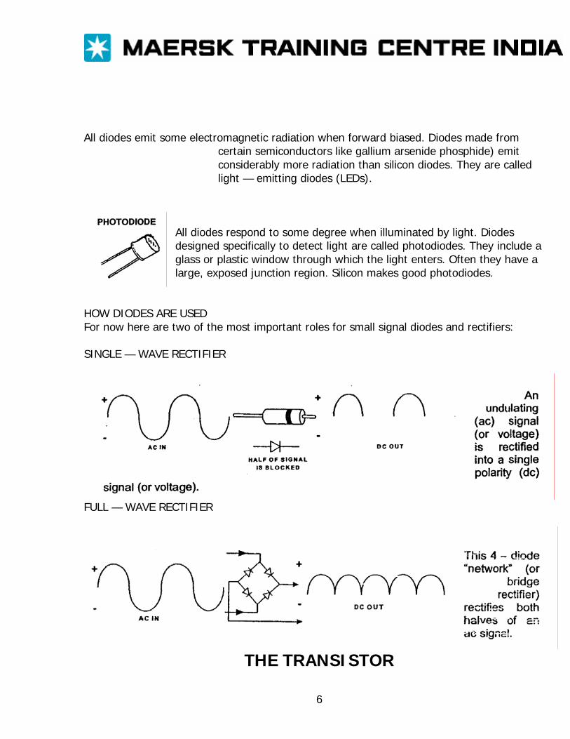
All diodes emit some electromagnetic radiation when forward biased. Diodes made from certain semiconductors like gallium arsenide phosphide) emit considerably more radiation than silicon diodes. They are called light — emitting diodes (LEDs).
All diodes respond to some degree when illuminated by light. Diodes designed specifically to detect light are called photodiodes. They include a glass or plastic window through which the light enters. Often they have a large, exposed junction region. Silicon makes good photodiodes.
HOW DIODES ARE USED For now here are two of the most important roles for small signal diodes and rectifiers: SINGLE — WAVE RECTIFIER
FULL — WAVE RECTIFIER
THE TRANSISTOR
6
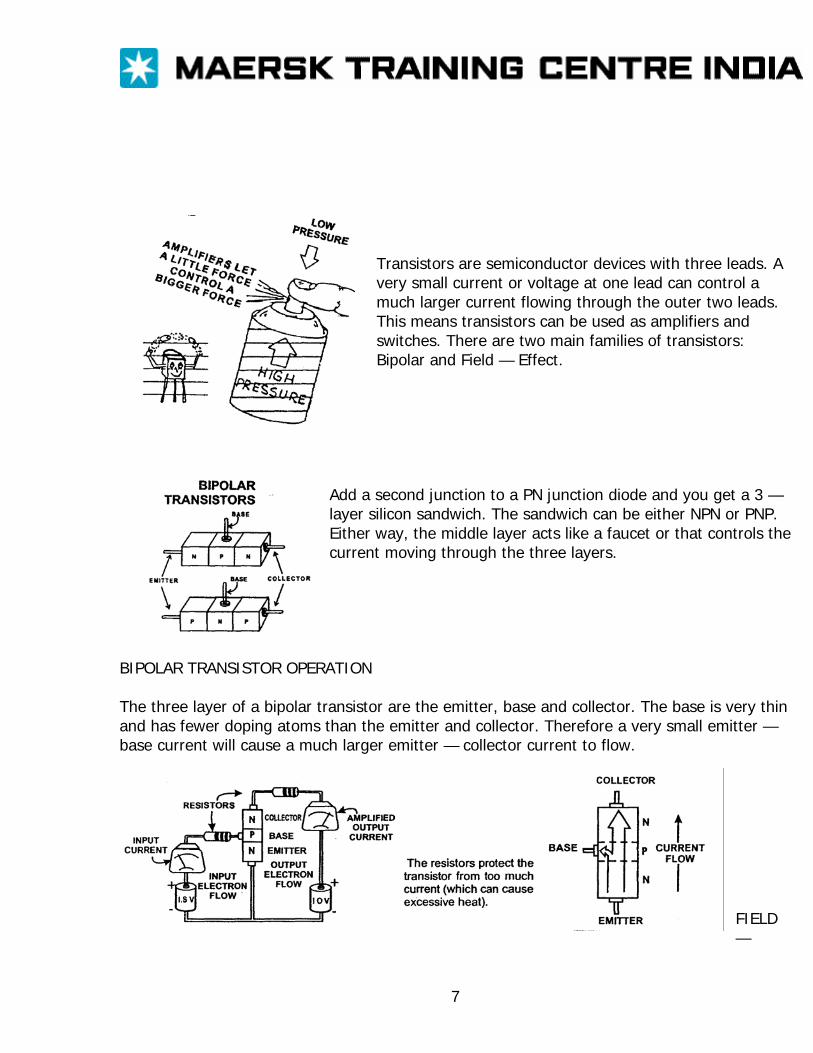
Transistors are semiconductor devices with three leads. A very small current or voltage at one lead can control a much larger current flowing through the outer two leads. This means transistors can be used as amplifiers and switches. There are two main families of transistors: Bipolar and Field — Effect.
Add a second junction to a PN junction diode and you get a 3 — layer silicon sandwich. The sandwich can be either NPN or PNP. Either way, the middle layer acts like a faucet or that controls the current moving through the three layers.
BIPOLAR TRANSISTOR OPERATION The three layer of a bipolar transistor are the emitter, base and collector. The base is very thin and has fewer doping atoms than the emitter and collector. Therefore a very small emitter — base current will cause a much larger emitter — collector current to flow.
FIELD —
7
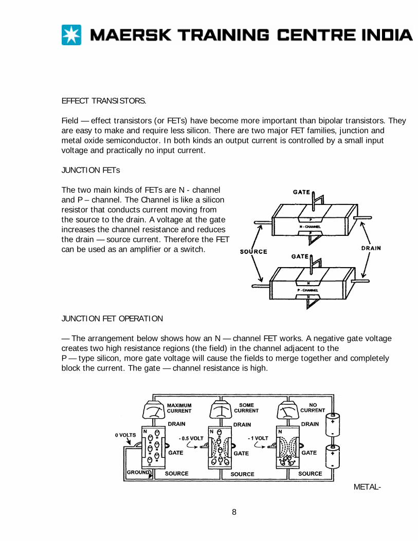
EFFECT TRANSISTORS. Field — effect transistors (or FETs) have become more important than bipolar transistors. They are easy to make and require less silicon. There are two major FET families, junction and metal oxide semiconductor. In both kinds an output current is controlled by a small input voltage and practically no input current. JUNCTION FETs The two main kinds of FETs are N - channel and P – channel. The Channel is like a silicon resistor that conducts current moving from the source to the drain. A voltage at the gate increases the channel resistance and reduces the drain — source current. Therefore the FET can be used as an amplifier or a switch. JUNCTION FET OPERATION — The arrangement below shows how an N — channel FET works. A negative gate voltage creates two high resistance regions (the field) in the channel adjacent to the P — type silicon, more gate voltage will cause the fields to merge together and completely block the current. The gate — channel resistance is high.
METAL-
8
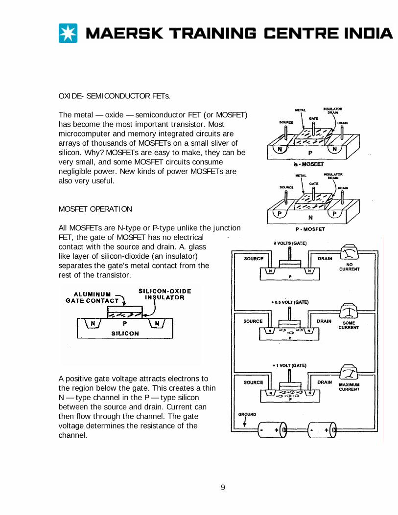
OXIDE- SEMICONDUCTOR FETs. The metal — oxide — semiconductor FET (or MOSFET) has become the most important transistor. Most microcomputer and memory integrated circuits are arrays of thousands of MOSFETs on a small sliver of silicon. Why? MOSFETs are easy to make, they can be very small, and some MOSFET circuits consume negligible power. New kinds of power MOSFETs are also very useful. MOSFET OPERATION All MOSFETs are N-type or P-type unlike the junction FET, the gate of MOSFET has no electrical contact with the source and drain. A. glass like layer of silicon-dioxide (an insulator) separates the gate’s metal contact from the rest of the transistor.
A positive gate voltage attracts electrons to the region below the gate. This creates a thin N — type channel in the P — type silicon between the source and drain. Current can then flow through the channel. The gate voltage determines the resistance of the channel.
9
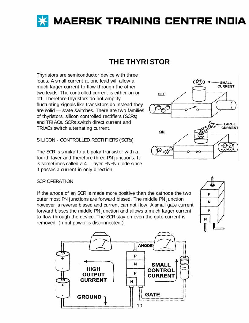
THE THYRISTOR Thyristors are semiconductor device with three leads. A small current at one lead will allow a much larger current to flow through the other two leads. The controlled current is either on or off. Therefore thyristors do not amplify fluctuating signals like transistors do instead they are solid — state switches. There are two families of thyristors, silicon controlled rectifiers (SCRs) and TRIACs. SCRs switch direct current and TRIACs switch alternating current. SILICON - CONTROLLED RECTIFIERS (SCRs) The SCR is similar to a bipolar transistor with a fourth layer and therefore three PN junctions. It is sometimes called a 4 – layer PNPN diode since it passes a current in only direction. SCR OPERATION If the anode of an SCR is made more positive than the cathode the two outer most PN junctions are forward biased. The middle PN junction however is reverse biased and current can not flow. A small gate current forward biases the middle PN junction and allows a much larger current to flow through the device. The SCR stay on even the gate current is removed. ( until power is disconnected.)
10
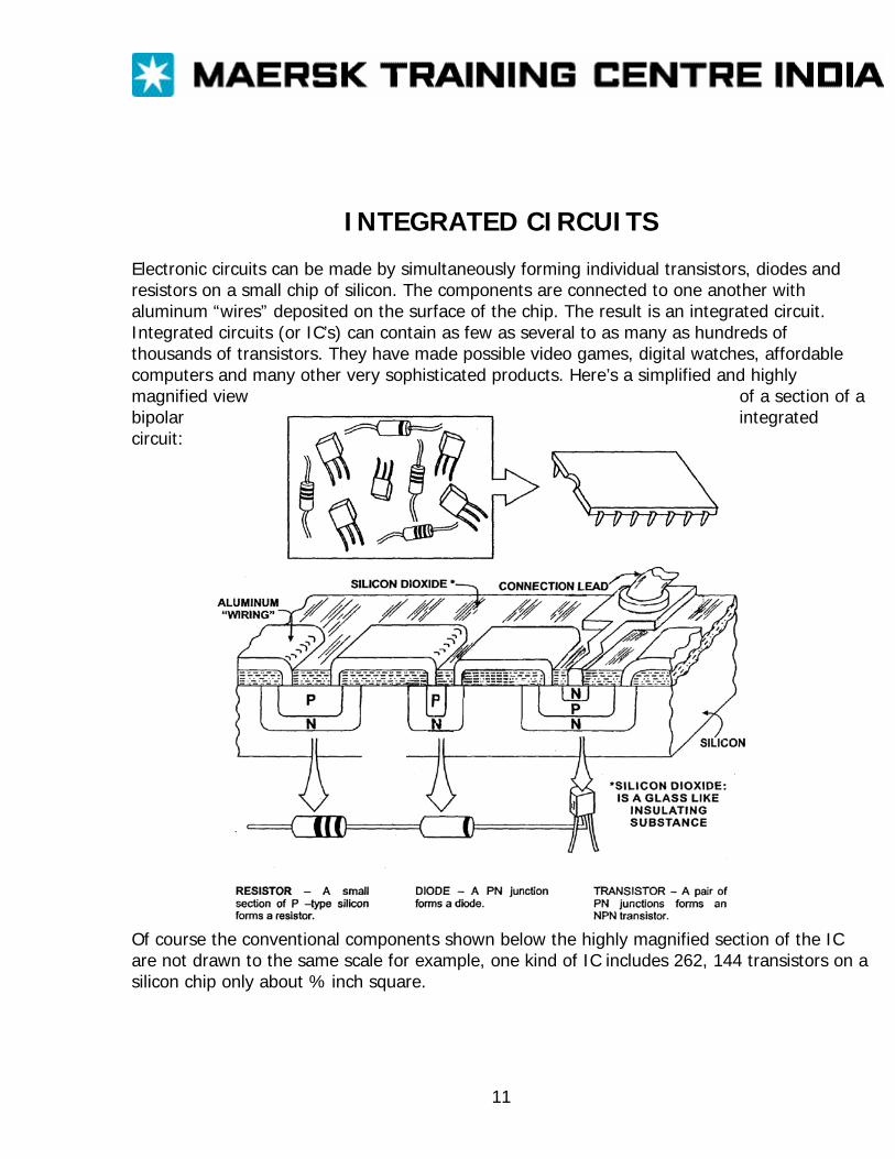
INTEGRATED CIRCUITS Electronic circuits can be made by simultaneously forming individual transistors, diodes and resistors on a small chip of silicon. The components are connected to one another with aluminum “wires” deposited on the surface of the chip. The result is an integrated circuit. Integrated circuits (or IC’s) can contain as few as several to as many as hundreds of thousands of transistors. They have made possible video games, digital watches, affordable computers and many other very sophisticated products. Here’s a simplified and highly magnified view of a section of a bipolar integrated circuit:
Of course the conventional components shown below the highly magnified section of the IC are not drawn to the same scale for example, one kind of IC includes 262, 144 transistors on a silicon chip only about % inch square.
11
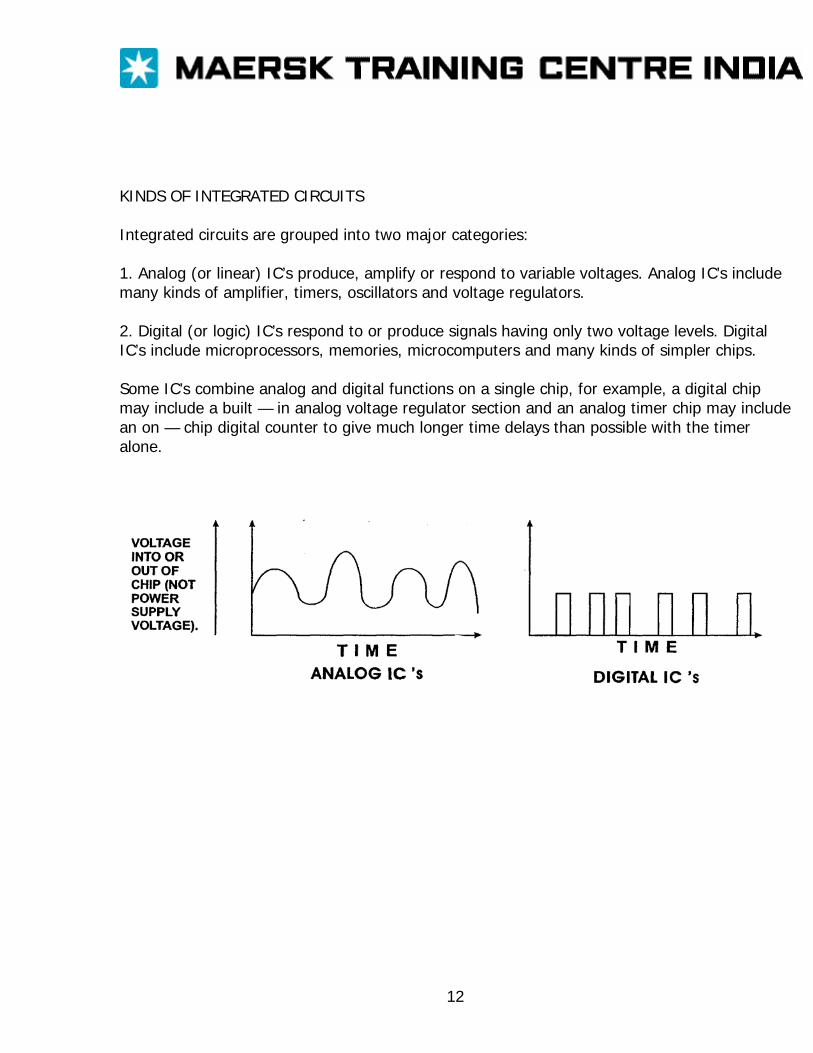
KINDS OF INTEGRATED CIRCUITS Integrated circuits are grouped into two major categories: 1. Analog (or linear) IC’s produce, amplify or respond to variable voltages. Analog IC’s include many kinds of amplifier, timers, oscillators and voltage regulators. 2. Digital (or logic) IC’s respond to or produce signals having only two voltage levels. Digital IC’s include microprocessors, memories, microcomputers and many kinds of simpler chips. Some IC’s combine analog and digital functions on a single chip, for example, a digital chip may include a built — in analog voltage regulator section and an analog timer chip may include an on — chip digital counter to give much longer time delays than possible with the timer alone.
12
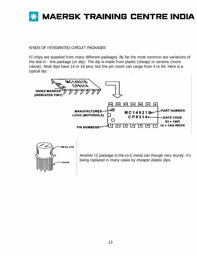
KINDS OF INTEGRATED CIRCUIT PACKAGES IC chips are supplied from many different packages. By far the most common are variations of the dial in - line package (or dip). The dip is made from plastic (cheap) or ceramic (more robust). Most dips have 14 or 16 pins, but the pin count can range from 4 to 64. Here is a typical dip:
Another IC package is the to-5 metal can though very sturdy; it’s being replaced in many cases by cheaper plastic dips.
13
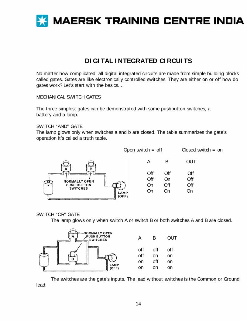
DIGITAL INTEGRATED CIRCUITS No matter how complicated, all digital integrated circuits are made from simple building blocks called gates. Gates are like electronically controlled switches. They are either on or off how do gates work? Let’s start with the basics.... MECHANICAL SWITCH GATES The three simplest gates can be demonstrated with some pushbutton switches, a battery and a lamp. SWITCH “AND” GATE The lamp glows only when switches a and b are closed. The table summarizes the gate’s operation it’s called a truth table.
Open switch = off Closed switch = on
A B OUT
Off Off Off Off On Off On Off Off On On On
SWITCH “OR” GATE
The lamp glows only when switch A or switch B or both switches A and B are closed. A B OUT off off off off on on on off on on on on
The switches are the gate’s inputs. The lead without switches is the Common or Ground lead.
14
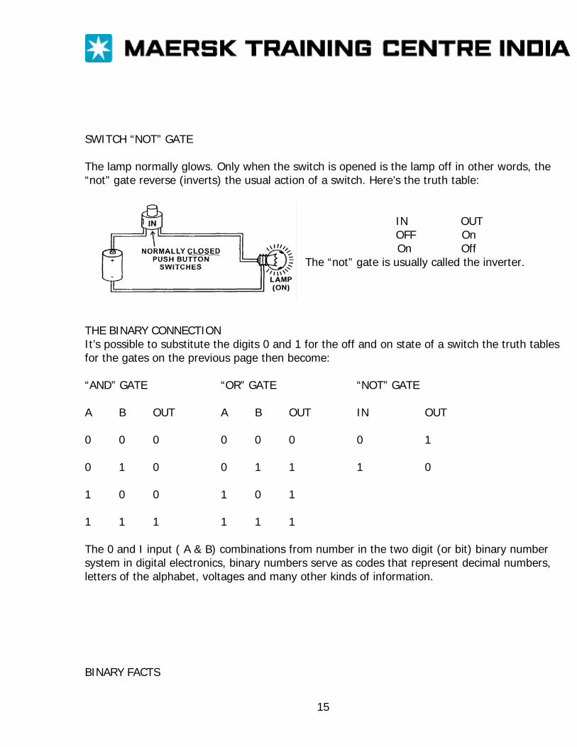
SWITCH “NOT” GATE The lamp normally glows. Only when the switch is opened is the lamp off in other words, the “not” gate reverse (inverts) the usual action of a switch. Here’s the truth table:
IN OUT OFF On
On Off The “not” gate is usually called the inverter.
THE BINARY CONNECTION It’s possible to substitute the digits 0 and 1 for the off and on state of a switch the truth tables for the gates on the previous page then become: “AND” GATE “OR” GATE “NOT” GATE A B OUT A B OUT IN OUT 0 0 0 0 0 0 0 1 0 1 0 0 1 1 1 0 1 0 0 1 0 1 1 1 1 1 1 1 The 0 and I input ( A & B) combinations from number in the two digit (or bit) binary number system in digital electronics, binary numbers serve as codes that represent decimal numbers, letters of the alphabet, voltages and many other kinds of information. BINARY FACTS
15
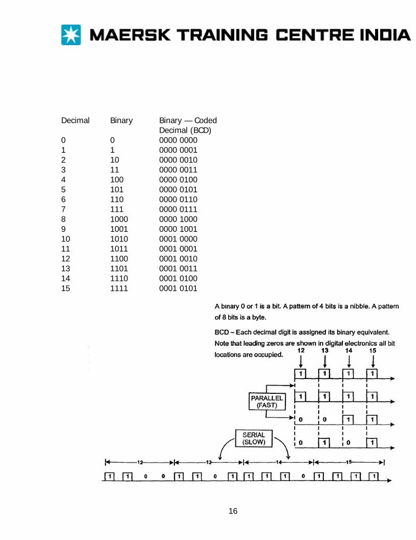
Decimal Binary Binary — Coded
Decimal (BCD) 0 0 0000 0000 1 1 0000 0001 2 10 0000 0010 3 11 0000 0011 4 100 0000 0100 5 101 0000 0101 6 110 0000 0110 7 111 0000 0111 8 1000 0000 1000 9 1001 0000 1001 10 1010 0001 0000 11 1011 0001 0001 12 1100 0001 0010 13 1101 0001 0011 14 1110 0001 0100 15 1111 0001 0101
16
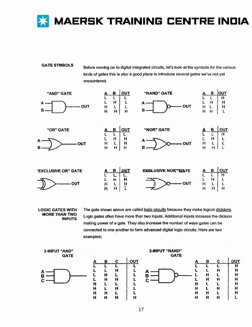
17
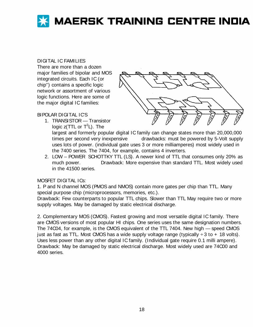
DIGITAL IC FAMILIES There are more than a dozen major families of bipolar and MOS integrated circuits. Each IC (or chip”) contains a specific logic network or assortment of various logic functions. Here are some of the major digital IC families: BIPOLAR DIGITAL IC’S
1. TRANSISTOR — Transistor logic z(TTL or T2L). The largest and formerly popular digital IC family can change states more than 20,000,000 times per second very inexpensive drawbacks: must be powered by 5-Volt supply uses lots of power. (individual gate uses 3 or more milliamperes) most widely used in the 7400 series. The 7404, for example, contains 4 inverters.
2. LOW – POWER SCHOTTKY TTL (LS). A newer kind of TTL that consumes only 20% as much power. Drawback: More expensive than standard TTL. Most widely used in the 41500 series.
MOSFET DIGITAL ICs: 1. P and N channel MOS (PMOS and NMOS) contain more gates per chip than TTL. Many special purpose chip (microprocessors, memories, etc.). Drawback: Few counterparts to popular TTL chips. Slower than TTL May require two or more supply voltages. May be damaged by static electrical discharge. 2. Complementary MOS (CMOS). Fastest growing and most versatile digital IC family. There are CMOS versions of most popular HI chips. One series uses the same designation numbers. The 74C04, for example, is the CMOS equivalent of the TTL 7404. New high — speed CMOS just as fast as TTL. Most CMOS has a wide supply voltage range (typically ÷3 to + 18 volts). Uses less power than any other digital IC family. (Individual gate require 0.1 milli ampere). Drawback: May be damaged by static electrical discharge. Most widely used are 74C00 and 4000 series.
18
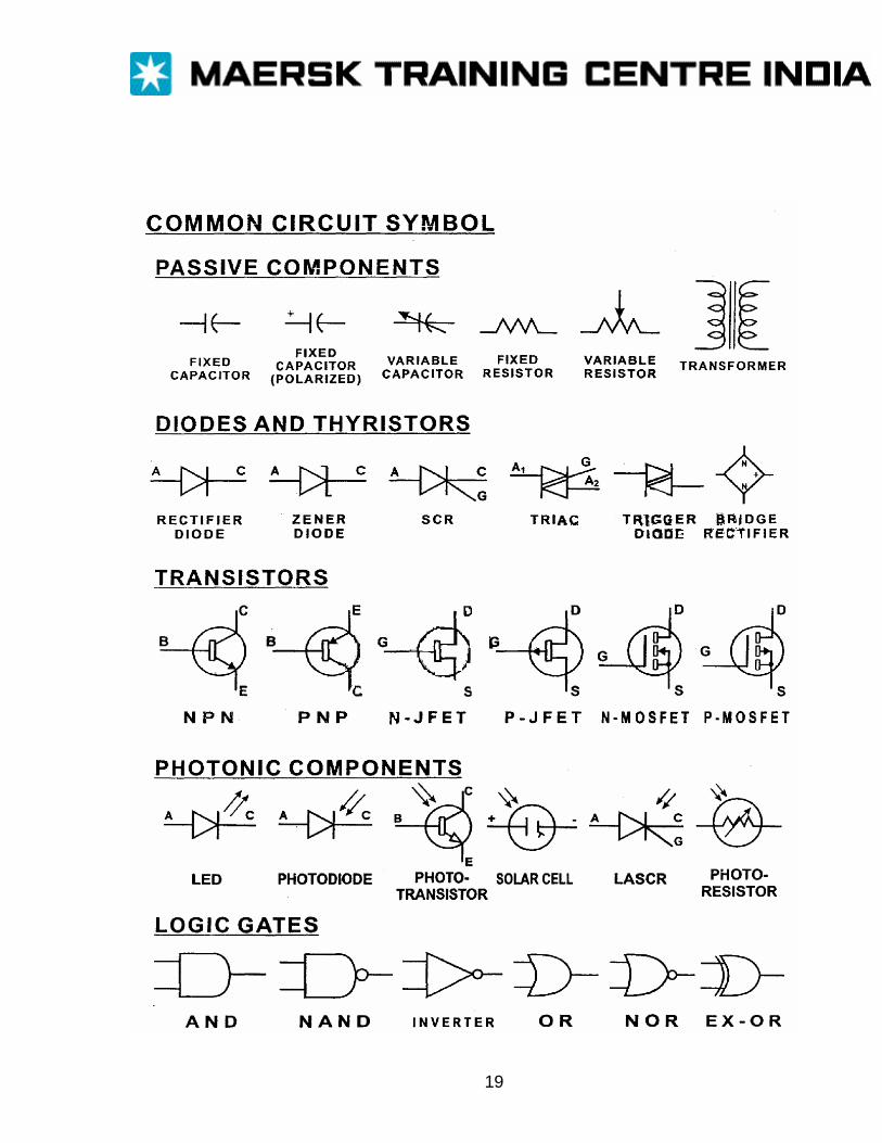
19
Electrical Installations (Except where expressly provided otherwise part D applies to passenger ships and cargo ships) Regulation 40 General: 1. Electrical installations shall be such that:
i) All electrical auxiliary services necessary for maintaining the ship in normal operational and habitable conditions will be ensured without recourse to the emergency source of electrical power: ii) Electrical services essential for safety will be ensured under various emergency conditions; and iii) The safety of passengers, crew and ship from electrical hazards will be ensured.
2. The Administration shall take appropriate steps to ensure uniformity in the implementation and application of the provisions of this part in respect of electrical Installations. Regulation 41 Main source of electrical power and lighting systems: 1.1 A main source of electrical power of sufficient capacity to supply all those services mentioned in regulation 4O.1.1 shall be provided. This main source of electrical power shall consist of at least two generating sets. 1.2 The capacity of these generating sets shall be such that in the event of any one generating set being stopped it will still be possible to supply those services necessary to provide normal operational Conditions of propulsion and safety. Minimum comfortable conditions of habitability shall also be ensured which include at least adequate service for cooking, heating, domestic refrigeration, mechanical ventilation, sanitary and fresh water. 1.3 The arrangements of the ship’s main source of electrical power shall be such that the services referred to in regulation 4O.1 .1 can be maintained regardless of the speed and direction of rotation of the propulsion machinery or shafting. 1.4 In addition, the generating sets shall be such as to ensure that with any one generator or its primary source of power out of operation, the remaining generating sets shall be capable of providing the electrical service necessary to start the main propulsion plant from a dead ship condition. The emergency source of electrical power may be used for the purpose of starting
1
from a dead ship condition if its capability either alone or combined with that of any other source of electrical power is sufficient by regulation 42.2.1 to 42.2.3 or 43.2.1 to 43.2.4. 1.5 Where transformers constitute an essential part of the electrical supply system required by this paragraph the system shall be so arranged to ensure the same continuity of the supply as is stated in this paragraph. 2.1 A main electric system which shall provide illumination through out those parts of the ship normally accessible to and used by passengers or crew shall be supplied from the main source of electrical power. 2.2 The arrangement of the main electric lighting system shall be such that a fire or other casualty in spaces containing the main source of electrical power, associated transforming equipment, if any, the main switchboard and the main lighting switchboard, will not render the emergency electric lighting system required by regulations 42.2.1 and 422.2 or 43.2.1, 43.2.2 and 43.2.3 inoperative. 2.3 The arrangement of the emergency electric lighting system shall be such that a fire or other casualty in spaces containing the emergency source of electrical power, associated transforming equipment, if any, the emergency switchboard and the emergency lighting switchboard will not render the main electric lighting system required by this regulation inoperative. 3 The main switchboard shall be so placed relative to one main generating station that, as far as is practicable, the integrity of the normal electrical supply may be affected only by a fire or other casualty in one space. An environmental enclosure for the main switchboard, such as may be provided by a machinery control room situated within the main boundaries of the space, is not to be considered as separating the switchboards from the generators. 4 Where the total installed electrical power of the main generating sets is in excess of 3 MW, the main bus bars shall be subdivided into at least two parts which shall normally be connected by removable links or other approved means; so far as is practicable, the connection of generating sets and any other duplicated equipment shall be equally divided between the parts. Equivalent arrangements may be permitted to the satisfaction of the Administration.
2
Regulation 42 Emergency source of electrical power in passenger ships (Paragraph 2.61 and 4.2 of this regulation apply to ships constructed on or after 1 February 1992) 1.1 A self — contained emergency source of electrical power shall be provided. 1.2 The emergency source of electrical power associated transforming equipment if any, transitional source emergency power, emergency switchboard and emergency lighting switchboard shall be located above the uppermost continuous deck and shall be forward of the collision bulkhead. 1.3 The location of the emergency source of electrical power and associated transforming equipment if any, the transitional source of emergency power, the emergency switchboard and the emergency electric lighting switchboards in relation to the main source of electrical power, associated transforming equipment if any, and the main switchboard shall be such as to ensure to the satisfaction of the Administration that a fire or other casualty in spaces containing the main source of electrical power, associated transforming equipment, if any, and the main switchboard or in any machinery space of category A will not interfere with the supply, control and distribution of emergency electrical power. As far as practicable, the space containing the emergency source of electrical power, associated transforming equipment, if any, the transitional source of emergency electrical power and the emergency switchboard shall not be contiguous to the boundaries of machinery spaces of category A or those spaces containing the main source of electrical power, associated transforming equipment, if any, or the main switchboard. 4 The transitional source of emergency electrical power required by paragraph 3.1.3 shall consist of an accumulator battery suitably located for use in an emergency which shall operate without recharging while maintaining the voltage of the battery throughout the discharge period within 12% above or below its nominal voltage and be of sufficient capacity and so arranged as to supply automatically in the event of failure of either the main or emergency source of electrical power at least the following services, if they depend upon an electrical source for their operation: 4.1 For half an hour: 1. the lighting required by paragraphs 2.1 and 2.1.1; 2. all services required by paragraphs 2.3.1, 2.3.3 and 2.3.4 unless such services have an independent supply for the period specified from an accumulator battery suitably located for use in an emergency. 4.2 Power to operate the watertight doors, as required by regulation 15.7.3.3, but not necessarily all of them simultaneously, unless an independent temporary source of stored
3
energy is provided. Power to the control indication and alarm circuits as required by regulation 15.7.2 for half an hour. 5.1 The emergency switchboard shall be installed as near as is practicable to the emergency source of electrical power. 5.2 Where the emergency source of electrical power is a generator, the emergency switchboard shall be located on the same space unless the operation of the emergency switchboard would thereby be impaired. 5.3 No accumulator battery fitted in accordance with this regulation shall be installed in the same space as the emergency switchboard. An indicator shall be mounted in a suitable place on the main switchboard or in the machinery control room to indicate when the batteries constituting either the emergency source of electrical power or transitional source of emergency electrical power referred to in paragraph 3.1.3 or 4 are being discharged. 5.4 The emergency switchboard shall be supplied during normal operation from the main switchboard by an inter connector feeder which is to be adequately protected at the main switchboard against overload and short circuit and which is to be disconnected automatically at the emergency switchboard upon failure of the main source of electrical power. Where the system is arranged for feedback operation, the inter connector feeder is also to be protected at the emergency switchboard at least against short circuit. 2.7 In a ship engaged regularly on voyages of short duration, the Administration if satisfied that an adequate standard of safety would be attained may accept a lesser period than the 36 h period specified in paragraphs 2.1 to 2.5 but not less than 12h. 3 The emergency source of electrical power may be either a generator or an accumulator battery, which shall comply with the following: 3.1 Where the emergency source of electrical power is a generator, it shall be: 1 driven by a suitable prime mover with an independent supply of fuel having a flash point (dosed cup test) of hot less than 43deg C; 2 started automatically upon failure of the main source of electrical power supply unless a transitional source of emergency electrical power in accordance with paragraph 3.1.3 is provided; where the emergency generator is automatically started, it shall be automatically connected to the emergency switchboard; those services referred to in paragraph 4 shall then be connected automatically to the emergency generator; and unless a second independent means of starting the emergency generator is provide the single source of stored energy shall be protected to preclude its complete depletion by the automatic starting system; 3 provided with a transitional source of emergency electrical power as specified in paragraph 4 unless an emergency generator is provided capable both of supplying the services mentioned
4
in that paragraph and of being automatically started and supplying the required load as quickly as is safe and practicable subject to a maximum of 45 s. 3.2 Where the emergency source of electrical power is an accumulator battery it shall be capable of; 1 carrying the emergency electrical load without recharging while maintaining the voltage of the battery throughout the discharge period within 12% above or below its nominal voltage; 2 automatically connecting to the emergency switchboard in the event of failure of the main source of electrical power; and 3 immediately supplying at least those services specified in paragraph 4. 4 The transitional source of emergency electrical power where required by paragraph 3.1.3 shall consist of an accumulator battery suitably located for use in an emergency which shall operate without recharging while maintaining the voltage of the battery throughout the discharge period within 12% above or below its nominal voltage and be of sufficient capacity and shall be so arranged as to supply automatically in the event of failure of either the main or the emergency source of electrical power for half an hour at least the following services if they depend upon electrical source for their operation:
1. the lighting required by paragraphs 2.1, 2.2 and 2.3.1. For this transitional phase, the required emergency electric lighting, in respect of the machinery space and accommodation and service spaces may be provided by permanently fixed, individual automatically charged, relay operated accumulator lamps; and
2. all services required by paragraphs 2.4.1, 2.4.3 and 2.4.4 unless such services have an independent supply for the period specified from an accumulator battery suitably located for use in an emergency.
5.1 The emergency switchboard shall be installed as near as is practicable to the emergency source of electrical power. 5.2 Where the emergency source of electrical power is a generator, the emergency switchboard shall be located in the same space unless the operation of the emergency switchboard would thereby be impaired. 5.3 No accumulator battery fitted in accordance with this regulation shall be installed in the same space as the emergency switchboard. An indicator shall be mounted in a suitable place on the main switchboard or in the machinery control room to indicate when the batteries
5
constituting either the emergency source of electrical power or the transitional source of electrical power referred to in paragraph 3.2 or 4 are being discharged. 5.4 The emergency switchboard shall be supplied during normal operation from the main switchboard by an interconnector feeder which is to be adequately protected at the main switchboard against overload and short circuit and which is to be disconnected automatically at the emergency switchboard upon failure of the main source of electrical power. Where the system is arranged for feedback operation, the interconnector feeder is also to be protected at the emergency switchboard at least against short circuit. 5.5 In order to ensure ready availability of the emergency source of electrical power, arrangements shall be made where necessary to disconnect automatically non- emergency circuits from the emergency switchboard to ensure that electrical power shall be available automatically to the emergency circuits. 6 The emergency generator and its prime mover and any emergency accumulator battery shall be so designed and arranged as to ensure that they will function at full rated power when the ship is upright and when inclined at any angle of list up to 22.5° or when inclined up to 100
either in the fore or aft direction; or is in any combination of angles within those limits. 7 Provision shall be made for the periodic testing of the complete emergency system and shall include the testing of automatic starting arrangements.
6
Regulation 44 Starting arrangements for emergency generating sets 1.Emergency generating sets shall be capable of being readily started in their cold condition at a temperature of 00 C. If this is impracticable, or if lower temperatures are likely to be encountered, provision acceptable to the Administration shall be made for the maintenance of heating arrangements, to ensure ready starting of the generating sets. 2 Each emergency generating set arranged to be automatically started shall be equipped with starting devices approved by the Administration with a stored energy capability of at least three consecutive starts. A second source of energy shall be provided for an additional three starts within 30 min unless manual starting can be demonstrated to be effective. 3 The stored energy shall be maintained at all times as follows: 1 electrical and hydraulic starting systems shall be maintained from the emergency switchboard; 2. compressed air starting systems may be maintained by the main or auxiliary compressed air receivers through a suitable non return valve or by an emergency compressor which if electrically driven, is supplied from the emergency switchboard. 3.all of these starting charging and energy storing devices shall be located in the emergency generator space; these devices are not to be used for nay purpose other than the operation of the emergency set. This does not preclude the supply to the air receiver of the emergency generating set from the main or auxiliary compressed -air system through the non return valve fitted in the emergency generator space. 4.1 Where automatic starting is not required, manual starting is permissible, such as manual cranking, inertia starter, manually charged hydraulic accumulators, or powder charge cartridges, where they can be demonstrated as being effective. 4.2 When manual starting is not practicable, the requirements of paragraphs 2 and 3 shall be complied with except that starting may be manually initiated.
7
Regulation 45
Precautions against shock, fire and other hazards of electrical origin 1.1 Exposed metal parts of electrical machines or equipment which are not intended to be live but which are liable under fault conditions to become live shall be earthed unless the machines or equipment are:
1. supplied at a voltage not exceeding 55 V direct current or 55 V, root mean square between conductors; autotransformers shall not be used for the purpose of achieving this voltage; or
2. supplied at a voltage not exceeding 250 V by safety isolating transforming device: or 3. constructed in accordance with the principle of double insulation.
1.2 The Administration may require additional precautions for portable electrical equipment for use in confined or exceptionally damp spaces where particular risks due to conductivity may exist. 1.3 All electrical apparatus shall be so constructed and so installed not to cause injury when handled or touched in the normal manner. 2 Main and emergency switchboard shall be so arranged as to give easy access as may be needed to apparatus and equipment, without danger to personnel. The sides and the rear and where necessary, the front of switchboards shall be suitably guarded. Exposed live parts having voltages to earth exceeding a voltage specified by administration shall not be installed on the front of such switchboards. Where necessary, nonconducting mats or gratings shall be provided at the front and rear of the switchboard. 3.1 the hull return system of distribution shall not be used for any purpose in a tanker, or for power, heating, or lighting in any other ship of 1,600 tons gross tonnage and upwards. 3.2 The requirement of paragraph 3.1 does not preclude under conditions approved by the Administration the use of: 1 Impressed current cathode protective systems; 2 limited and locally earthed systems; or 3 insulation level monitoring devices provided the circulation current does not exceed 30 mA under the most unfavorable conditions. 3.3 Where the hull return system is used, all final sub circuits, i.e. all circuits fitted after the last protective device, shall be two-wire and special precautions shall be taken to the satisfaction of the Administration.
8

4.1 Earthed distribution systems shall not be used in a tanker. The Administration may exceptionally permit in a tanker the earthing of the neutral for alternating current power networks for 3,000 V (line to line) and over, provided that any possible resulting current does not flow directly through any of the dangerous spaces. 7 Lighting fittings shall be so arranged as to prevent temperature rises which could damage the cable and wiring, and to prevent surrounding material from becoming excessively hot. 8 All lighting and power circuits terminating in a bunker or cargo space shall be provided with a multiple-pole switch outside the space for disconnecting such circuits. 9.1 Accumulator batteries shall be suitably housed, and compartments used primarily for their accommodation shall be properly connected and efficiently ventilated. 9.2 Electrical or other equipment which may constitute a source of ignition of flammable vapors shall not be permitted in these compartments except as permitted in paragraph 1. 9.3 Accumulator batteries shall not be located in sleeping quarters except where hermitically sealed to the satisfaction of the administration. 10 No electrical equipment shall be installed in any space where flammable mixtures are liable to collect including those on board tankers or in compartments assigned principally to accumulator batteries, in paint lockers, acetylene stores or similar spaces, unless the Administration is satisfied that such equipment is; 1 essential for operational purpose; 2 of a type which will not ignite the mixture concerned; 3 appropriate to the space concerned; and 4 appropriately certified for safe usage in the dusts, vapors or gases likely to be encountered. 11 In a passenger ship, distribution systems shall be so arranged that fire in any main vertical zone as is defined in regulation 11-2/3.9 will not interfere with services essential for safety in any other such zone. This requirement will be met if main and emergency feeders passing through any such zone are separated both vertically and horizontally as widely as is practicable.
9
PartE Additional requirement for periodically unattended machinery spaces
(Part E applies to cargo ships except that regulation 54 refers to passenger ships) Regulation 50 Communication A reliable means of vocal communication shall be provided between the main machinery control room or the propulsion machinery control position as appropriate, the navigating bridge and the engineer officers’ accommodation. Regulation 51 1 An alarm system shall be provided indicating any fault requiring attention and Alarm system shall; 1 be capable of sounding an audible alarm in the main machinery control room or at the propulsion machinery control position, and indicate visually each separate alarm function at a suitable position; 2 have a connection to the engineers’ public rooms and to each of the engineers’ cabins through a selector switch to ensure connection, to at least one of those cabins. Administrations may permit equivalent arrangements; 3 activate an audible and visual alarm on the navigating bridge for any situation, which requires action by way of the officer on watch; 4 as far as is practicable be designed on the fail to-safety principal; and 5 activate the engineers alarm required by regulation 38 if an alarm function has not received attention locally within a limited time. 2.1 The alarm system shall be continuously powered and shall have an automatic change over to a stand-by power supply in case of loss of normal supply. 2.2 Failure of the normal power supply of the alarm system shall be indicated by an alarm. 3.1 The alarm system shall be able to indicate at the same time more than one fault and the acceptance of any alarm shall not inhibit another alarm. 3.2 Acceptance at the position referred to in paragraph 1 of any alarm condition shall be indicated at the positions where it was shown. Alarms shall be maintained until they are accepted and the visual indications of individual alarms shall remain until the fault has been corrected, when the alarm system shall automatically reset to the normal operating condition.
10
Regulation 52 Safety systems A safety shall be provided to ensure that serious malfunction in machinery or boiler operations, which present an immediate danger, shall initiate the automatic shutdown of that part of the plant and that an alarm shall be given. Shutdown of the propulsion system shall not be automatically activated except in cases, which could lead to serious damage, complete breakdown, or explosion. Where arrangements for overriding the shutdown of the main propelling machinery are fitted, these shall be such as to preclude inadvertent operation. Visual means shall be provided to indicate when the override has been activated. Regulation 53 Special requirements for machinery, boiler and electrical installations The special requirements for the machinery, boiler and electrical installation shall be to the satisfaction of the Administration and shall include at least the requirements of this regulation. 2 The main source of electrical power shall comply with the following;
2.1 Where the electrical power can normally be supplied by one generator, suitable load-shedding arrangements shall be provided to ensure the integrity of supplies to services required for propulsion and steering as well as the safety of the ship. In case of loss of the generator in operation, adequate provision shall be made for automatic starting and connecting to the main switchboard of a stand-by generator of sufficient capacity to permit propulsion and steering and to ensure the safety of the ship with automatic restarting of the essential auxiliaries including where necessary sequential operations The Administration may dispense with this requirement for a ship of less than 1600 gross tonnage if it is considered impracticable.
2.2 If the electrical power is normally supplied by more than one generator simultaneously in parallel operation provision shall be made for instance by load shedding, to ensure that in case of loss of one of these generating sets, the remaining ones are kept in operation without overload to permit propulsion and steering, and to ensure the safety of the ship.
3 Where standby machines are required for other auxiliary machinery essential to propulsion, automatic change over devices shall be provided. 4 Automatic control and alarm system. 4.1 The control system shall be such that the services needed for the operation of
11
the main propulsion machinery and its auxiliaries are ensured through the necessary automatic arrangements. 4.2 An alarm shall be given on the automatic change-over. 4.3 An alarm system complying with regulation 51 shall be provided for all important pressures, temperatures and fluid levels and other essential parameters. 4.4 A centralized control position shall be arranged with the necessary alarm panels and instrumentation indicating any alarm. 5 Means shall be provided to keep the starting air pressure at the required level where internal combustion engines are used for main propulsion. Regulation 54 Special consideration in respect of passenger ships
Passenger ships shall be specially considered by the Administration as to whether or not their machinery spaces may be periodically unattended and if so whether additional requirement to those stipulated in these regulations are necessary to achieve equivalent safety to that of normally attended machinery spaces.
12
Annex Amendments to the 1974 SOLAS Convention
CHAPTER 114 Construction — Subdivision and stability, machinery and electrical installations
Access to spaces in the cargo area of oil tankers Regulation 2 Definitions
1 Add the following after paragraph 11: ‘12 An oil tanker is the oil tanker defined in regulation I of Annex I of the protocol of 1978 relating to the International Convention for the Prevention of Pollution from Ships, 1973”. 2 Add a new regulation 12-2:
Regulation 12-2 Access to spaces in the cargo area of oil tankers
1. This regulation applies to oil tankers constructed on or after 1 October1994. 2. Access to cofferdams, ballast tanks, cargo tanks and other spaces in the cargo area
shall be direct from the open deck and such as to ensure their complete inspection. Access to double bottom space may be through a cargo pump room. Pump room, deep cofferdam, pipe tunnel or similar compartments subject to consideration of ventilation aspects.
3. For access through horizontal openings, hatches, or manholes, the dimensions shall be sufficient to allow a person wearing a self contained breathing apparatus and protective equipment to ascend or descend any ladder without obstruction and also to provide a clear opening to facilitate the hoisting of an injured person from the bottom of the space. The minimum clear opening should be not less than 600mm x 600mm.
4. For access through vertical openings, or manholes providing passage through the length and breath of the space, the minimum clear opening should be not less than 600 mm x 800 mm at a height of not more than 600 mm from the bottom shell plating unless gratings or other footholds are provided.
5. For oil tankers of less than 5,999 tonnes deadweight smaller dimensions may be approved by the Administration in special circumstances, if the ability to traverse such openings or to remove an injured person can be proved to the satisfaction of the Administration.
13
Regulation 37 Communication between navigating bridge and machinery space 3 Number the present paragraph as paragraph 1 and add the following: “2 For ships constructed on or after-i October 1994 the following requirements apply in lieu of the provisions of paragraph 1:
At least two independent means shall be provided for communicating orders from the navigating bridge to the position in the machinery space or in the control room from which the speed and direction of thrust of the propellers are normally controlled; one of these shall be an engine-room telegraph which provides visual indication of the orders and responses both in the machinery spaces and on the navigating bridge. Appropriate means of communication shall be provided from the navigating bridge and the engine-room to any other position from which the speed or direction of thrust of the propellers may be controlled.”
Regulation 42 Emergency source of electrical power in passenger ships 4 insert the following paragraph after paragraph 3.2: “3.3The following provision in paragraph 3.1.2 shall not apply to ships constructed on or after 1 October 1994;
Unless a second independent means of starting the emergency generating set is provided, the single source of stored energy shall be protected to preclude its complete depletion by the automatic starting system.”
Regulation43 Emergency source of electrical power in cargo ships 5 Insert the following paragraph after paragraph 3.2; 3.3 The following provision in paragraph 3.1.2shall not apply to ships constructed on or after 1 October 1994: Regulation 44 Starting arrangements for emergency generating sets 6 Insert the following paragraph after paragraph 2. 2.1 Ships constructed on or after October 1994, ln lieu of the provision of second sentence of paragraph 2 shall comply with the following requirements: The source of stored energy shall be protected to preclude critical depletion by the automatic starting system, unless a second independent means of starting is provided in addition a
14
second source of energy shall be provided for an additional three starts within 30 min unless manual starting can be demonstrated to be effective. Regulation 45 Precautions against shock, fire and other hazards of electrical origin 7 Insert the following after paragraph 32: “3.2-1 For ship constructed on or after 1 October 1994, the requirement of paragraph 3.1 does not preclude the use of limited and locally earthed systems, provided that any possible resulting current does not flow directly through any dangerous spaces.” 8 Insert the following after paragraph 4.2: “4.3 Ships constructed on or after 1 October 1994, in lieu of the provisions of paragraph 4.1 shall comply with the following requirements:
1. Except as permitted by paragraph 4.3.2, earthed distribution system shall not be used in a tanker.
2. The requirement of paragraph 4.3.1 does not preclude the use of earthed intrinsically safe circuits and in addition, under conditions approved by the Administration, the use of the following earthed systems:
2.1 power-supplied control circuits and instrumentation circuits where technical or safety reasons preclude the use of a system with no connection to earth, provided the current in the hull is limited to not more than 5 A in both normal and fault conditions; or 2.2 limited and locally earthed systems, provided that any possible resulting current does not flow directly through any of the dangerous spaces; or 2.3 alternating current power network of 1,000 V root mean square (line to line) and over, provided that any possible resulting current does not flow directly through any of the dangerous spaces. 2.6 An excessive charging rate causes acid mist to be carried out of the vents onto adjacent surfaces. This should be cleaned off with diluted ammonia water or soda solution, and affected areas then dried.
3 Alkaline batteries
3.1 The general safety precautions with the type of battery are the same as for the lead-
acid batteries with the following exceptions. 3.2 The electrolyte in these batteries is alkaline but is similarly corrosive. It should not
be allowed to come into contact with the skin or clothing. In the case of contact with the skin the affected parts should be washed with copious quantities of clean fresh water but if burns ensure boracic powder or a saturated solution boracic powder is should be applied. Eyes should be washed out thoroughly with plenty of clean fresh water followed immediately with a solution of boracic powder at the rate
15

of one teaspoonful to 1/2 litre or 1 pint of water). This solution should be always accessible when the electrolyte is handled.
3.3 Unlike lead batteries, metal cases of alkaline batteries remain live at all times and care should be taken not to touch them or to allow metal tools to come into contact with them.
1.17 Alkaline and lead —acid batteries should be kept in separate compartments. Where both lead-acid and alkaline batteries are in use, great care should be exercised to keep apart the materials and tools used in servicing each type, as contamination of the electrolyte may cause deterioration of battery performance and mixing of the two electrolytes produces a vigorous chemical reaction which could be very dangerous. 1.18 Both acid and alkaline electrolytes are highly corrosive. Immediate remedial action should be taken to wash off any accidental splashes on the person or on equipment. Hands should always be washed as soon as the work has finished. 1.19 Batteries should always be transported in the upright position to avoid spillage of electrolyte. A sufficient number of men should be employed since the batteries are heavy and painful strains or injury can otherwise easily result (see Chapter 11). 2 Lead-acid batteries 2.1 When the electrolyte is being prepared, the concentrated sulphuric acid should be added slowly to the water, if water is added to the acid, the heat generated may cause an explosion of steam, spattering acid over the person handling it. 2.2 Goggles, rubber gloves and protective apron should be worn when acid is handled. 2.3 To neutralize acid on skin or clothes, copious quantities of clean fresh water should be used. 2.4 An eyewash bottle should be to hand in the compartment for immediate use on the eyes in case of accident. This bottle should be clearly distinguishable by touch from acid or other containers, so that it may be easily located by a person who is temporarily blinded. 2.5 The corrosion products which from round the terminals of batteries are injurious to skin and eyes. They should be removed by brushing, away from the body. Terminals should be protected with petroleum jelly. 2.6 Modem equipment often embodies a master crystal enclosed in an oven; the supply to the oven is taken from an independent source and is not disconnected when the
16
transmitter is switched off and the mains switch is off. Mains voltage will be present inside the transmitter, and care should be taken. 2.7 Before work is begun in the EHT section of a transmitter or other HT apparatus, with the mains switched off, all HT capacitors should be discharged using an insulated jumper & inserting a resistor in the circuit to slow the rate of discharge. This precaution should be taken even where the capacitors have permanent discharge resistors fitted. 2.8 An electrolytic capacitor that is suspect, or shows blistering, should be replaced, since it is liable to explode when electrical supply is on. There is a similar risk when an electrolytic capacitor is discharged by a short circuit. 2.9 Work at or near live equipment should be avoided if possible but where it is essential for the safety of the ship or for testing purpose then the additional precautions described in Chapter22, section 9.6-12 should be taken. 3 Valves and semiconductor devices 3.1 Valves being removed from equipment which has recently been operating should be grasped with a heat resistant cloth; in case of large valves, e.g. power amplifier, OP and modulators, which reach a high temperature in operation, cooling down time should be allowed before they are removed. Severe bums can result if they touch bare skin. 3.2 Cathode ray tubes and large thermionic valves should be handled with care; although they implode when broken, there is still a risk of severe cuts from sharp-edged glass fragments. Some special purpose devices contain vapor or gas at high pressure, for example Trigatron, but these are usually covered with a protective fibre network to contain the glass should they explode. 3.3 Beryllia (beryllium oxide) dust is very dangerous if inhaled or if it penetrates the skin through a cut or abrasion. It may be present in some electronic components. Cathode ray tubes, power transistors, diodes and thyristors containing it will be usually identified by the manufacturers’ information provided, but lack of such information should not be taken as a positive indication of its absence. Those heat sink washers which contain it are highly polished and look like dark brass. These items should be carefully stored in their original packing until required. 3.4 Physical damage to components of this kind whether they are new or defective is likely to produce dangerous dust; abrasion should be avoided, they should not be worked by tool and encapsulations should be left intact. Excessive heat can be dangerous, but normal soldering with thermal shunt is safe. Damaged or broken parts should be separately and securely packed following the manufacturers’ instructions for return or disposal. 3.4 Persons handling parts containing beryllia should wear protective clothing, including
gloves, to prevent beryllia coming into contact with the skin. Tweezers should be
17
used where practicable if the skin does become contained with the dust, affected parts, particularly any cuts should be cleaned without delay.
4 Work on apparatus on extension runners or on the bench 4.1 Chassis on extension runners should be firmly fixed, either by self-locking devices or Or by chocks before any work is done. 4.2 Where units are awkward or heavy for one person to handle easily, assistance should be sought. Strain, rupture or a slipped disc can result from a lone effort. 4.3 Any chassis on the bench should be firmly wedged or otherwise secured to Prevent it overbalancing or moving. Should a live chassis overbalance, no attempt should be made to grab it. 4.4 Sharp edges and tag connectors on a chassis can cause cuts. Should the tag be alive and the skin is pierced, the shock experienced will be out of proportion to the voltage. 4.5 Temporary connections should be soundly made. Flexible extension cables should have good insulation and adequate current carrying capacity. Storage batteries 1 General 1.1 When a battery is being charged it ‘gases’, giving off both hydrogen and oxygen. Because hydrogen is easily ignited in concentrations ranging from 4 per cent in air, battery containers and compartments should be kept adequately ventilated to prevent an accumulation of dangerous gas. 1.2 Smoking and any type of open flame should be prohibited in a battery compartment. A conspicuous notice to this effect should be displayed at the entrance to the compartment. 1.3 Lighting fittings in battery compartments should be properly maintained at all times with protective glasses in position and properly tightened. If cracked or broken glasses cannot be replaced immediately, the electric circuit should be isolated until replacements are obtained. 1.4 No unauthorized modifications or additions should be made to electrical equipment (including lighting, fittings in battery compartments).
18
1.5 Portable electric lamps and tools, and other portable power tools which might give rise to sparks should not be used in battery compartments. 1.6 The battery compartment should not be used as a store for any material or gear not associated with the batteries. 1.7 A short circuit of even one cell may produce an arc or sparks which may cause an explosion of any hydrogen present. Additionally, the very heavy current which can flow in the short circuiting wire or tool may cause bums due to rapid overheating of the metal. 1.8 Insulation and/or guarding of cables in battery compartments should be maintained in good condition. 1.9 All battery connections should be kept clean and tight to avoid sparking and overheating. Temporary clip-on connections should never be used as they may work loose due to vibration and cause a spark or short circuit. 1.10 Metal tools, such as wrenches and spanners, should never be placed on top of batteries as they may cause sparks or short circuits. The use of insulated tools is recommended. 1.11 Jewellery, watches and rings etc should be removed when working on batteries. A short circuit through any of these items will heat it rapidly and may cause a severe skin bum. If rings cannot be removed, they should be heavily taped in insulating material. 1.12 All circuits fed by the battery should be switched off when leads are being connected or disconnected. If a battery is in sections, it may be possible to reduce the voltage between cells in the work area, and hence the severity of an accident short circuit or electric shock, by removing the jumper leads between sections before work is begun. It should be appreciated that whilst individual cell voltage may not be present a shock risk, dangerous voltages can exist where numbers of cells are connected together in series. A lethal shock needs a current of only a few tens of milliamps and particular care should be exercised where the voltage exceeds 50 V. 1.13 Battery cell vent plugs should be screwed tight while connection are being made or broken. 1.14 The ventilation tubes of battery boxes should be examined regularly to ensure that they are free from obstruction.
19

1.15 Lids of battery boxes should be fastened while open for servicing and properly secured again when the work is finished. 1.16 Batteries should be kept battened in position to prevent shifting in rough weather.
20
Servicing radio and associated electronic equipment General 1.1 Exposure to dangerous levels of microwave radiation should be avoided by strict adherence to instructions about special precautions contained in manufacturers’ handbooks. Radar sets should not be operated with wave guides disconnected unless it is necessary for servicing purposes, when special precautions should be taken. 1.2 Work should not be undertaken within the marked safety radius of Satellite Terminal Antennae unless its transmitter has been rendered inoperative. 1.3 Eyes are particularly vulnerable to microwave and ultraviolet radiation. Care should be taken to avoid looking directly into a radar aerial or wave guide while it is in operation or where arcing or sparking is likely to occur. 1.4 Exposure to dangerous levels of X-ray radiation may occur in the vicinity of faulty high voltage valves. Care should be exercised when fault tracing in the modulator circuits of radar can lead to X-ray radiation where the anode voltage is in excess of 5000V. 1.5 Vapours of some solvents used for degreasing are toxic, particularly carbon Tetrachloride which should never be used. Great care should be exercised when using solvents particularly in confined spaces; there should be no smoking. Manufacturer’s instructions should be followed. 1.6 Some dry recorder paper used in echo sounders and facsimile recorders give off toxic fumes in use. The equipment should be well-ventilated to avoid inhalation of the fumes. 1.7 Radio transmitters and radar equipment should not be operated when men are working in the vicinity of aerials; the equipment should be isolated from mains supply and radio transmitters earthed. When equipment has been isolated, warning notices should be placed on transmitting and radar equipment and at the mains supply point, to prevent apparatus being switched on until clearance has been received from those concerned that they have finished the outside work. 1.8 Aerials should be rigged out of reach of persons standing at normal deck level or mounting easily accessible parts of the superstructure. If that is impracticable, safety screens should be erected. 1.9 Notices warning of the danger of high voltage should be displayed near radio transmitter aerials and lead-through insulators.
21
2 Electrical hazards 2.1 Conditions on board ship often create greater than normal risks of electric shock (see Chapter 22, section 9). It should also be borne in mind that cuts and abrasions significantly reduce skin resistance. 2.2 Fuse should be removed from equipment before work is begun, and retained while the work is proceeding. 2.3 Where accumulators are used they should be disconnected at source; otherwise precautions should be taken to avoid short circuiting the accumulator terminals with consequent risk of bums. 2.4 Live chassis connected to one side of the mains are usually marked appropriately and should be handled with caution. Where the mains are AC and a transformer is interposed, the chassis is usually connected to the earth side of the supply but this should be verified using an appropriate meter. 2.5 When some types of equipment are switched off the mains switches are left on some parts may remain live; power should always be cut off at the mains.
22
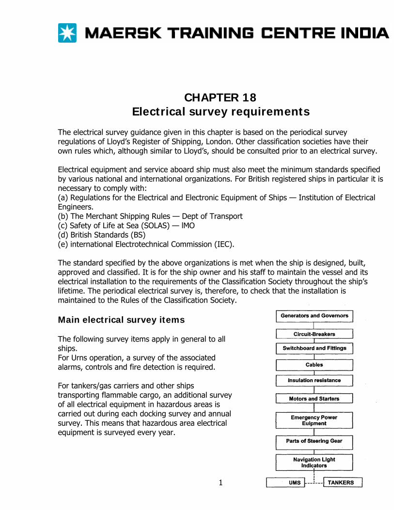
CHAPTER 18 Electrical survey requirements
The electrical survey guidance given in this chapter is based on the periodical survey regulations of Lloyd’s Register of Shipping, London. Other classification societies have their own rules which, although similar to Lloyd’s, should be consulted prior to an electrical survey. Electrical equipment and service aboard ship must also meet the minimum standards specified by various national and international organizations. For British registered ships in particular it is necessary to comply with: (a) Regulations for the Electrical and Electronic Equipment of Ships — Institution of Electrical Engineers. (b) The Merchant Shipping Rules — Dept of Transport (c) Safety of Life at Sea (SOLAS) — lMO (d) British Standards (BS) (e) international Electrotechnical Commission (IEC). The standard specified by the above organizations is met when the ship is designed, built, approved and classified. It is for the ship owner and his staff to maintain the vessel and its electrical installation to the requirements of the Classification Society throughout the ship’s lifetime. The periodical electrical survey is, therefore, to check that the installation is maintained to the Rules of the Classification Society. Main electrical survey items The following survey items apply in general to all ships. For Urns operation, a survey of the associated alarms, controls and fire detection is required. For tankers/gas carriers and other ships transporting flammable cargo, an additional survey of all electrical equipment in hazardous areas is carried out during each docking survey and annual survey. This means that hazardous area electrical equipment is surveyed every year.
1
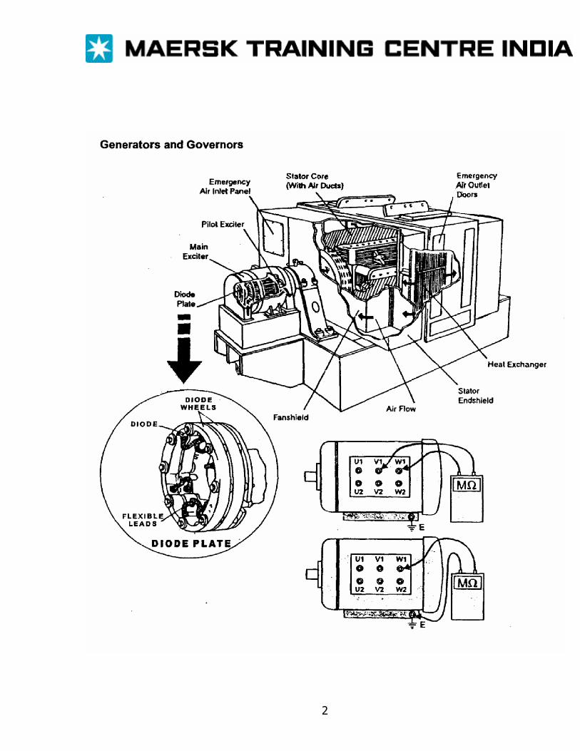
2
The surveyor will require that main and emergency generators are clean, respond correctly to controls and load changes, and slow stable operation when required to run in parallel with other generators. Generator windings on stator and rotor must be free of dust, oil and moisture. A visual check will be made for any obvious deterioration, abrasion or cracking of the insulation around the end winding coils on the stator. An insulation test to earth and between stator phase windings (if the neutral point can be disconnected at the terminal box: should be carried out while the machine is still hot after running on load.) QUESTION Would an IR reading of 0.5 M: to earth be acceptable? ANSWER Although a minimum of 1 MΩ is generally specified for new equipment Lloyd’s rules suggest that 0.1M: is acceptable. However, most surveyors would insist on at least 1 kΩ /volt, i.e.440kΩ, say, O.5MΩ as a reasonable minimum value for a 440V generator. Remember to disconnect all AVR equipment, instrument connections and generator heater supplies when testing for lR. The rotor circuits must also be tested for insulation value taking care to short out the rotating shaft diodes of a ‘brushless’ excitation system if the diodes have a low PIV (Peak Inverse Voltage) rating. Special attention to the contact surface of any commutator or slip-rings is required. The contact surfaces must be smooth and concentric without any sign of pitting or deep grooves. Carbon brushes must be of adequate length maintained at the correct spring pressure and properly contoured onto its rotating commutator or slip-ring. Be sure to remove any excess carbon dust in the vicinity of the brush gear and around rotor coils. Generator running test confirm the proper operation of governor and AVR controls with correct voltage, frequency and current values indicated on the generator control panel. Governor droop (typically 4%) and its response to sudden load changes must be within the declared specification for the prime mover/generator combination. Stability of load sharing of kW and kVAR (or load current/power factor) between two or more generators running in parallel must be demonstrated. Circuit-breakers
3

A visual examination of circuit-breakers in main, emergency and section boards will usually precede operational tests. The surveyor will particularly check the condition of main, arcing and auxiliary contacts for signs or wear, misalignment and overheating. A similar inspection of fixed and moving isolator contacts at the rear of a circuit- breaker will be made. Arc chutes must be clean, free of arc debris and correctly aligned. All internal wiring should be in good condition and its end connections must be tight. All mechanical linkages will be checked for any signs of wear or stress. Tests on a circuit-breaker will include ‘close’ and ‘trip’ operations while in its ‘isolated’ position (i.e. not connected in circuit). The racking mechanism for moving the breaker from the service to the ‘isolated’ position must be demonstrated to be free moving and the local main terminals must be seen to be shuttered off when the breaker is withdrawn. Emergency hand charging (if fitted) of the closing spring will be tested. Correct operation of the mechanical indicators to show whether the breaker is ‘open’, ‘closed’ or isolated, is required. The under voltage release mechanism and over current trip settings for level and time delay may have to be demonstrated to the surveyor’s satisfaction. Over current trips are typically set for 125% of Ml load current with a typical time delay of 20 secs, but this can vary to suit the thermal capacity of the generator. Although the over current and time delay settings on the breaker can be seen to be correctly adjusted to the desired values, only a proper current injection test will prove these settings. In this test the circuit-breaker is isolated from the bus- bar and suitable currents from a current injection set are fed directly through the closed circuit-breaker (primary injection) or through the over current relay (secondary injection). This is usually a specialist job. Circuit-breaker time delay mechanisms with oil dash pots must have the pots filled to correct level with clean oil of a type recommended by the manufacturer. Switchboards and fittings An obvious survey requirement for any switchboard, section board or distribution board is that they are clean. This includes all internal surface as well as the external panel surface, instrument faces and control switches. A thorough cleaning job on the inside of the main switchboard can only be safely carried out when the board is completely ‘dead’ (all generators stopped and prime mover locked off). All the main bus-bar and auxiliary connections throughout the boards should be checked for tightness during the dead period of a major internal clean up. Overheating signs at a connection junction are probably due to a loose joint. Bus-bar supports will be examined for surface cracking and damage to the insulation material. All internal wiring within the switchboard panels must be securely. Cable entries at the bottom
4
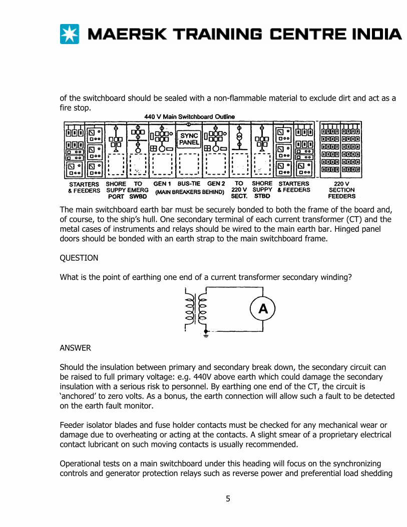
of the switchboard should be sealed with a non-flammable material to exclude dirt and act as a fire stop.
The main switchboard earth bar must be securely bonded to both the frame of the board and, of course, to the ship’s hull. One secondary terminal of each current transformer (CT) and the metal cases of instruments and relays should be wired to the main earth bar. Hinged panel doors should be bonded with an earth strap to the main switchboard frame. QUESTION What is the point of earthing one end of a current transformer secondary winding?
ANSWER Should the insulation between primary and secondary break down, the secondary circuit can be raised to full primary voltage: e.g. 440V above earth which could damage the secondary insulation with a serious risk to personnel. By earthing one end of the CT, the circuit is ‘anchored’ to zero volts. As a bonus, the earth connection will allow such a fault to be detected on the earth fault monitor. Feeder isolator blades and fuse holder contacts must be checked for any mechanical wear or damage due to overheating or acting at the contacts. A slight smear of a proprietary electrical contact lubricant on such moving contacts is usually recommended. Operational tests on a main switchboard under this heading will focus on the synchronizing controls and generator protection relays such as reverse power and preferential load shedding
5
trips. Typical reverse power trip settings may be 10 to 15% of the generator power rating with a time delay of 3-6 seconds for a diesel drive. Equivalent setting for a turbo alternator may be 2-5% and 5Sec. Such time delay settings must allow for the operating practice on the ship. For example, the cargo winches and cranes may, at times, feed power back into the supply network. Under light load conditions such regenerative feed back may cause generator to trip on reverse power if its time delay was set too short. Cables Apart from a megger test on main cable run (e.g. along the flying bridge of a tanker) the survey of cables and their installation is largely based on a close visual examination. Inspection would search for any external damage of a cable’s outer sheath and wire or basket weaves armoring (if fitted). The cable must, of course, be adequately supported along horizontal and vertical runs by suitable cable clips or ties. Where cable runs along an open deck have expansion loops, these must be examined for abrasion and wear. Where cables pass though fire check bulkheads they must be correctly glanded or pass through stopper boxes, which prevent the passage of fire between compartments. Probably the most common ship-board cable insulations used are EPR (ethylene propylene rubber) or butyl rubber which is sheathed with either PCP (polychloroprene) or CSP (chlorosulphonated polyethelene). QUESTION What are the functions of EPR or butyl and PCP or CSP? ANSWER EPR or butyl rubber are good electrical insulators but are not mechanically strong or resistant to oil. This why a sheath of PCP or CSP which is stronger and has greater oil and fire resistance is fitted around the inner insulation. Where EPR / butyl cable terminations may be subjected to oil vapor it is usual to tape or sleeve the cable ends to prevent deterioration of the insulation. Check that such taping is secure. Flexible cables to light fittings, power tools, etc., should be inspected for mechanical damage. In normal operation a flexible cable may be repeatedly dragged and chafed so reducing its safety. If in doubt replace flexible cables. A copper strap or flexible earthing braid/wire is used to bond the steel frame of all electrical motors and other equipment to the ship’s hull.
6
QUESTION Why? ANSWER Without an earth strap, a loose internal wire may touch the frame causing it to become ‘live’ at mains voltage with obvious danger to operator’s. The earth strap electrically ‘anchors’ the frame to the hull to eliminate shock hazards. Insulation resistance The surveyor will require a list which shows the results of recent insulation tests on all main 440V and 220v circuits. Such a list should also indicate the test date(s). weather conditions (hot, humid etc.,) together with comments relevant to the test conditions (e.g. machine hot or cold) For essential items such as generators and main motors, the surveyor will be more interested in the IR trend, so a set past result showing the insulation history of such machines may be requested. Totally enclosed fan ventilated (TEFV) induction motors require little attention as their windings are protected against the external atmosphere. The surveyor will be more likely to concentrate on motor with ‘Drip proof. Weatherproof and ‘Deck-watertight’ enclosures. It may be necessary to open up such motors to check for ingress of oil and water, which could damage insulation and cause internal corrosion. Special machines such as dc commutator or ac slip ring types used, for example, on an electric windlass, must have their rotary contacts and brush gear checked. Cargo cranes and winches are not strictly part of a survey as they are not considered essential to safety of the ship. A running test on a motor will reveal any vibration problems, undue noise and worn out bearings. On-load, the motor running current (shown on the starter ammeter) should be checked against the value indicated on the motor, rating plate. With starters and associated control gear such as remote stop/start buttons, regulating resistors etc., an inspection will check mainly for badly burned and misaligned contacts. The general condition of starter equipment will be examined. This would include an inspection for loose connections, worn ‘pigtails’ on moving contacts, badly carbonized arc-chutes and signs of overheating on coils, transformers and resistors. Dust and weather sealing features on a starter must be in place and in a serviceable condition. Functional checks will test the normal operation of the starter from its normal, remote and emergency control (if applicable) positions. Signal status lamps showing the motor/starter condition, e.g. running’, off ‘tripped’, etc, must be demonstrated as working correctly.
7
Over current trip settings should be compared with the motor full-load current rating. Motor starter back-up fuse size and type may be checked against the ship’s/manufacturer’s drawings and the motor rating. Emergency power and associated equipment This section surveys the operation of the emergency generator and or battery power equipment (Inspection of the emergency generator itself is covered under the heading of Generators and Governors) The emergency generator must be started, manually or automatically, while the initiation sequence and operation of starting equipment is observed. Electrical supplies taken from the emergency switchboard should be checked as receiving their proper voltage, current and frequency when powered from the emergency generator. Emergency lighting, fire pump and other emergency electrical equipment must be functioning correctly. Electrical interlocking arrangements between main and emergency switchboard must be checked. Auto start initiation relays, whether voltage or frequency operated, will be examined and tested. The ship’s emergency battery installation and its charging rectifier will be examined. In particular the battery environment must be dry and well ventilated. The battery tops must be clean with non-corroded terminal posts and connections. Grease all connections with petroleum jelly. Battery electrolyte should be at its proper level and have the correct value of the specific gravity as checked on a hydrometer. Safety notices and personnel safety clothes (gloves, apron and goggles) should be available adjacent to the batteries. The ventilation arrangements for the battery locker will be checked. Battery charging equipment should be given the normal checks for dirt, overheating, loose connections and correct functioning of indicators, instruments and alarms. Parts of steering gear
8
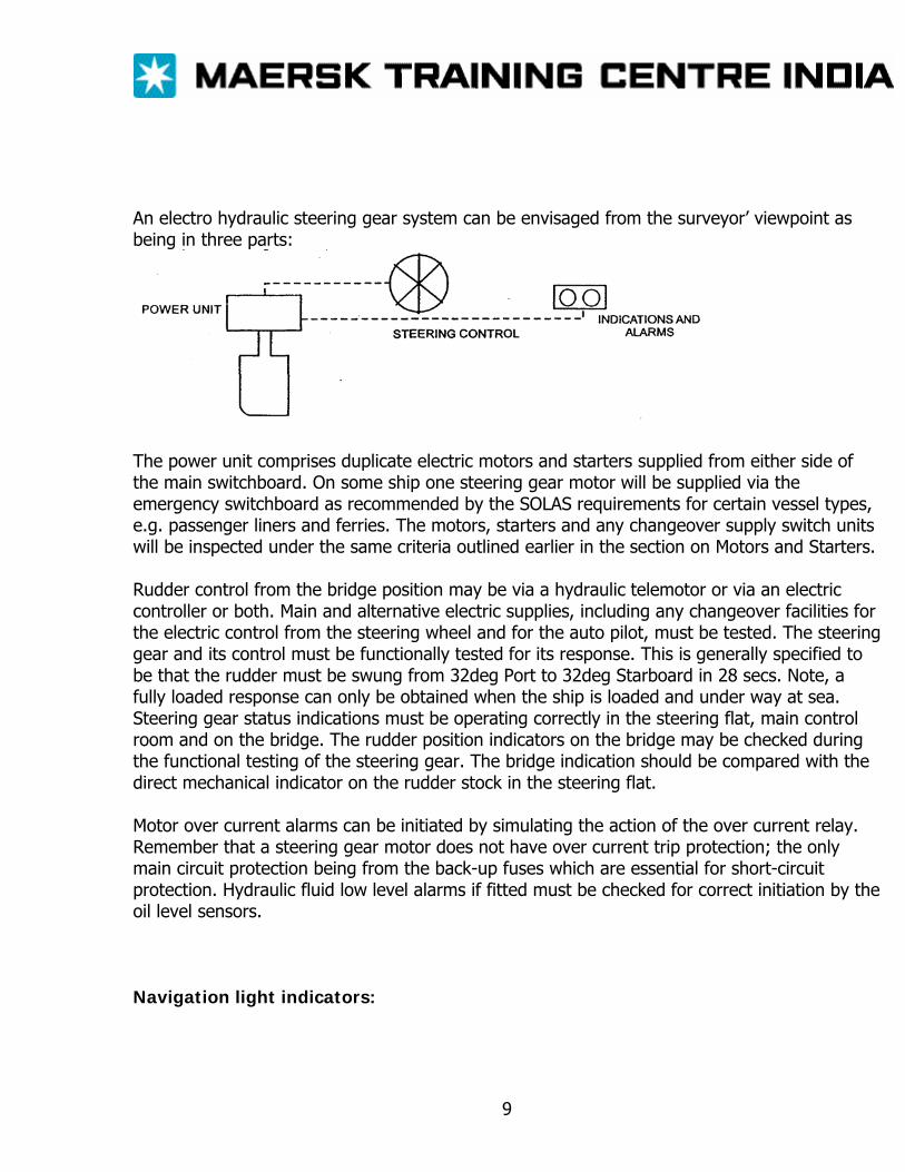
An electro hydraulic steering gear system can be envisaged from the surveyor’ viewpoint as being in three parts:
The power unit comprises duplicate electric motors and starters supplied from either side of the main switchboard. On some ship one steering gear motor will be supplied via the emergency switchboard as recommended by the SOLAS requirements for certain vessel types, e.g. passenger liners and ferries. The motors, starters and any changeover supply switch units will be inspected under the same criteria outlined earlier in the section on Motors and Starters. Rudder control from the bridge position may be via a hydraulic telemotor or via an electric controller or both. Main and alternative electric supplies, including any changeover facilities for the electric control from the steering wheel and for the auto pilot, must be tested. The steering gear and its control must be functionally tested for its response. This is generally specified to be that the rudder must be swung from 32deg Port to 32deg Starboard in 28 secs. Note, a fully loaded response can only be obtained when the ship is loaded and under way at sea. Steering gear status indications must be operating correctly in the steering flat, main control room and on the bridge. The rudder position indicators on the bridge may be checked during the functional testing of the steering gear. The bridge indication should be compared with the direct mechanical indicator on the rudder stock in the steering flat. Motor over current alarms can be initiated by simulating the action of the over current relay. Remember that a steering gear motor does not have over current trip protection; the only main circuit protection being from the back-up fuses which are essential for short-circuit protection. Hydraulic fluid low level alarms if fitted must be checked for correct initiation by the oil level sensors. Navigation light indicators:
9

Essentially, the surveyor will expect to prove that the navigation light indicator operates correctly and give the appropriate alarms. A broken wire or lamp can be simulated by pulling the appropriate fuse. The power supply for the navigation lights must be duplicated. The alternate supply being derived from the emergency switchboard (usually supply being derived from the emergency switchboard) and the change over facilities must be checked. Although the actual light fittings to navigation are part of the Safety Equipment Survey, the electrical survey naturally include a check on the supply cables to the lights. UMS Operation If your ship is classified for Unattended Machinery Space (UMS) operation, the electrical survey will be extended to include all the alarms, fire detection, controls and fail-safe features of such an installation. All alarms associated with the main engine, auxiliary machines, lubrication and cooling are to test for correct operation. Testing of the electrical circuits from the various sensors is relatively straightforward. This can be achieved by operating the sensor switch by hand or by simulating the switch action under the expected alarms condition. To prove that the overall sensor (pressure stat, flow switch, level switch, temperature switch, etc.) is functioning correctly is obviously more involved. Often, specialist contractors may be called upon to service and calibrate the sensors and alarm annunciators. Particular attention will be paid to the main engine and auxiliary generators in respect of their alarms for lubrication and cooling. Initiation and action of auto shut-down features will be tested. Essential drives for lubrication, cooling and fuel supply are duplicated and arranged so that one pump can be selected on a duty/standby basis. Loss of pressure at the duty pump should automatically start up the standby unit. Automatic start-up of the emergency generator must be demonstrated. The initiation of the under voltage or under-frequency relay can usually be accomplished by pulling the fuses in the detection unit. The emergency generator should then run up to speed and supply power to the emergency switchboard. UMS requirement demand that a standby main generator is started automatically on loss of the duty generator. The standby generator is to start and close onto the bus- bar within 45 secs. This is followed by automatic sequential re-starting of essential auxiliaries for lubrication, cooling, fuel and steering. The correct functioning of the system will be tested. The duplicate bilge level alarms together with automatic bilge pumping must be proven to the surveyor’s satisfaction. The main and standby electric power supplies to the overall alarm monitoring system must be inspected and tested. The standby power arrangement usually includes battery back-up. It will
10
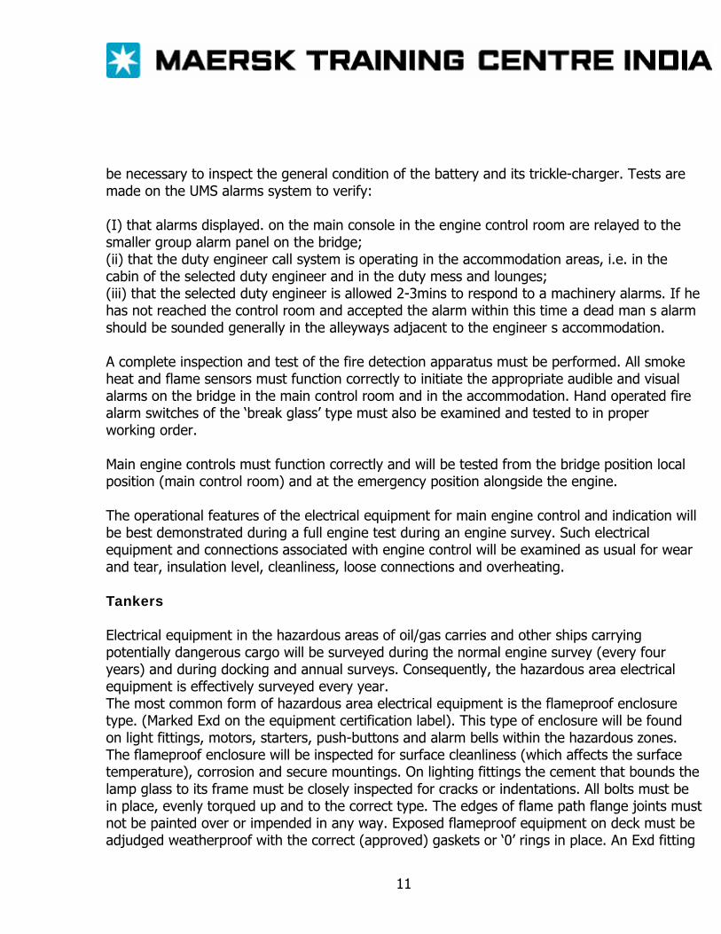
be necessary to inspect the general condition of the battery and its trickle-charger. Tests are made on the UMS alarms system to verify: (I) that alarms displayed. on the main console in the engine control room are relayed to the smaller group alarm panel on the bridge; (ii) that the duty engineer call system is operating in the accommodation areas, i.e. in the cabin of the selected duty engineer and in the duty mess and lounges; (iii) that the selected duty engineer is allowed 2-3mins to respond to a machinery alarms. If he has not reached the control room and accepted the alarm within this time a dead man s alarm should be sounded generally in the alleyways adjacent to the engineer s accommodation. A complete inspection and test of the fire detection apparatus must be performed. All smoke heat and flame sensors must function correctly to initiate the appropriate audible and visual alarms on the bridge in the main control room and in the accommodation. Hand operated fire alarm switches of the ‘break glass’ type must also be examined and tested to in proper working order. Main engine controls must function correctly and will be tested from the bridge position local position (main control room) and at the emergency position alongside the engine. The operational features of the electrical equipment for main engine control and indication will be best demonstrated during a full engine test during an engine survey. Such electrical equipment and connections associated with engine control will be examined as usual for wear and tear, insulation level, cleanliness, loose connections and overheating. Tankers Electrical equipment in the hazardous areas of oil/gas carries and other ships carrying potentially dangerous cargo will be surveyed during the normal engine survey (every four years) and during docking and annual surveys. Consequently, the hazardous area electrical equipment is effectively surveyed every year. The most common form of hazardous area electrical equipment is the flameproof enclosure type. (Marked Exd on the equipment certification label). This type of enclosure will be found on light fittings, motors, starters, push-buttons and alarm bells within the hazardous zones. The flameproof enclosure will be inspected for surface cleanliness (which affects the surface temperature), corrosion and secure mountings. On lighting fittings the cement that bounds the lamp glass to its frame must be closely inspected for cracks or indentations. All bolts must be in place, evenly torqued up and to the correct type. The edges of flame path flange joints must not be painted over or impended in any way. Exposed flameproof equipment on deck must be adjudged weatherproof with the correct (approved) gaskets or ‘0’ rings in place. An Exd fitting
11
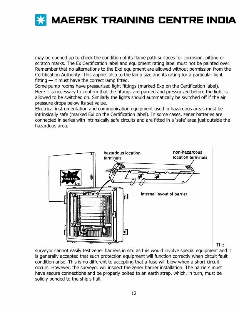
may be opened up to check the condition of its flame path surfaces for corrosion, pitting or scratch marks. The Ex Certification label and equipment rating label must not be painted over. Remember that no alternations to the Exd equipment are allowed without permission from the Certification Authority. This applies also to the lamp size and its rating for a particular light fitting — it must have the correct lamp fitted. Some pump rooms have pressurized light fittings (marked Exp on the Certification label). Here it is necessary to confirm that the fittings are purged and pressurized before the light is allowed to be switched on. Similarly the lights should automatically be switched off if the air pressure drops below its set value. Electrical instrumentation and communication equipment used in hazardous areas must be intrinsically safe (marked Exi on the Certification label). In some cases, zener batteries are connected in series with intrinsically safe circuits and are fitted in a ‘safe’ area just outside the hazardous area.
The surveyor cannot easily test zener barriers in situ as this would involve special equipment and it is generally accepted that such protection equipment will function correctly when circuit fault condition arise. This is no different to accepting that a fuse will blow when a short-circuit occurs. However, the surveyor will inspect the zener barrier installation. The barriers must have secure connections and be properly bolted to an earth strap, which, in turn, must be solidly bonded to the ship’s hull.
12

13
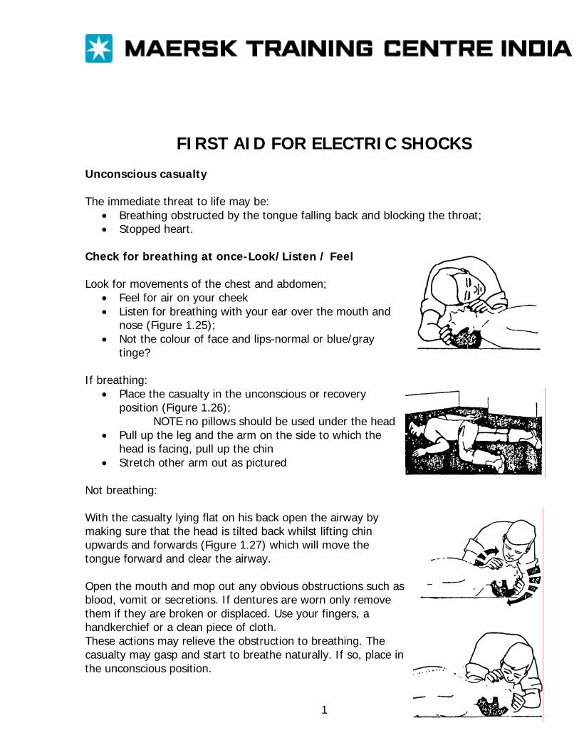
FIRST AID FOR ELECTRIC SHOCKS Unconscious casualty The immediate threat to life may be:
• Breathing obstructed by the tongue falling back and blocking the throat; • Stopped heart.
Check for breathing at once-Look/Listen / Feel Look for movements of the chest and abdomen;
• Feel for air on your cheek • Listen for breathing with your ear over the mouth and
nose (Figure 1.25); • Not the colour of face and lips-normal or blue/gray
tinge? If breathing:
• Place the casualty in the unconscious or recovery position (Figure 1.26);
NOTE no pillows should be used under the head • Pull up the leg and the arm on the side to which the
head is facing, pull up the chin • Stretch other arm out as pictured
Not breathing: With the casualty lying flat on his back open the airway by making sure that the head is tilted back whilst lifting chin upwards and forwards (Figure 1.27) which will move the tongue forward and clear the airway. Open the mouth and mop out any obvious obstructions such as blood, vomit or secretions. If dentures are worn only remove them if they are broken or displaced. Use your fingers, a handkerchief or a clean piece of cloth. These actions may relieve the obstruction to breathing. The casualty may gasp and start to breathe naturally. If so, place in the unconscious position.
1

Still not breathing: Begin artificial respiration at once-seconds count.
• Open the airway by making sure that the head is tilted back whilst lifting the chin upwards and forwards.
• Work from the side in a convenient position; • Pinch the casualty’s nose with your index finger and thumb. After taking a full breath,
seal your lips about the patient’s mouth and blow into his mouth until you see the chest rise. This should take about 2 seconds for full inflation. (Figure1.28).
• Give two effective inflations quickly, then note if the colour of the face and lips is improving.
If there is improvement: Continue the artificial respiration, maintaining a rate of about a dozen inflations each minute. It may help your timing to count to five, slowly, between inflations; See section above on if breathing’. If there is no improvement:
• Listen for heart sounds (Figure 1.29); • Feel the pulse at the neck (Figure 1.29);
If no heart beat is felt, the heart has stopped. A trained first -aider must begin chest compression at once. Unless circulation is restored, the brain will be without oxygen and the person will be dead in four to six minutes: The casualty must be lying on his back on a hard surface e g deck other wise the compression will be lost; Place your hands together as shown in Figure 1.30 Press(1/2 second duration, 100 times a minute) firmly and rapidly on the middle of the lower half of the breast bone sufficient produce a downward movement of about 4cm(Figure 1.31); Artificia1 respiration (Figure 1.30) must also be carried out when giving heart compression since breathing stops when the heart stops. It can be given by one person, alternately compressing 15 times and then filling the lungs with air twice or, ideally, by two people-one giving heart compression and the other giving artificial respiration, at a ratio of 5 chest compressions to 1 lung inflation; if the heart starts to beat the colour of the face and lips will improve and the eye pupils will get smaller;
2
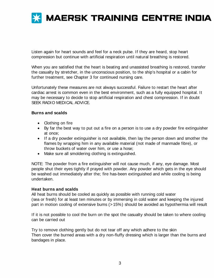
Listen again for heart sounds and feel for a neck pulse. If they are heard, stop heart compression but continue with artificial respiration until natural breathing is restored. When you are satisfied that the heart is beating and unassisted breathing is restored, transfer the casualty by stretcher, in the unconscious position, to the ship’s hospital or a cabin for further treatment, see Chapter 3 for continued nursing care. Unfortunately these measures are not always successful. Failure to restart the heart after cardiac arrest is common even in the best environment, such as a fully equipped hospital. It may be necessary to decide to stop artificial respiration and chest compression. If in doubt SEEK RADIO MEDICAL ADVICE. Burns and scalds
• Clothing on fire • By far the best way to put out a fire on a person is to use a dry powder fire extinguisher
at once; • If a dry powder extinguisher is not available, then lay the person down and smother the
flames by wrapping him in any available material (not made of manmade fibre), or throw buckets of water over him, or use a hose;
• Make sure all smoldering clothing is extinguished. NOTE: The powder from a fire extinguisher will not cause much, if any, eye damage. Most people shut their eyes tightly if prayed with powder. Any powder which gets in the eye should be washed out immediately after the; fire has-been extinguished and while cooling is being undertaken. Heat burns and scalds All heat burns should be cooled as quickly as possible with running cold water (sea or fresh) for at least ten minutes or by immersing in cold water and keeping the injured part in motion cooling of extensive bums (>15%) should be avoided as hypothermia will result If it is not possible to cool the burn on the spot the casualty should be taken to where cooling can be carried out Try to remove clothing gently but do not tear off any which adhere to the skin Then cover the burned areas with a dry non-fluffy dressing which is larger than the burns and bandages in place.
3
Electrical burns and electrocution
• Make sure you do not become the next casualty when approaching any person who is in contact with electricity;
• If possible, switch off the current; • Otherwise, insulate yourself. Remove your watch and rings, wear rubber boots or stand
on an insulating mat, thick DRY newspaper or wood; • Alternatively, pull the casualty from the source of supply with an insulated flex or push
him away with a strong non-conductor, such as a piece of DRY wood; • Check immediately for breathing and heartbeat; • If not breathing, give artificial respiration; • If heart is stopped, give chest compression and artificial respiration; • Send for help; • When the casualty is breathing, cool any burned areas and apply a clean, dry, non-fluffy
covering to the burned area. Chemical splashes Remove contaminated clothing. Drench with water to wash the chemical away; Carry on washing for at least ten minutes. If you are in any doubt that the chemical has been completely cleared from the skin, repeat the washing for a further ten minutes; Give priority to washing the eyes if affected, as they are particularly vulnerable to chemical splashes. If only one eye is affected, incline the head to that side to prevent the chemical from running across into the other eye.
4
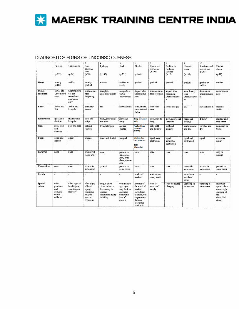
DIAGNOSTICS SIGNS OF UNCONSCIOUSNESS
5
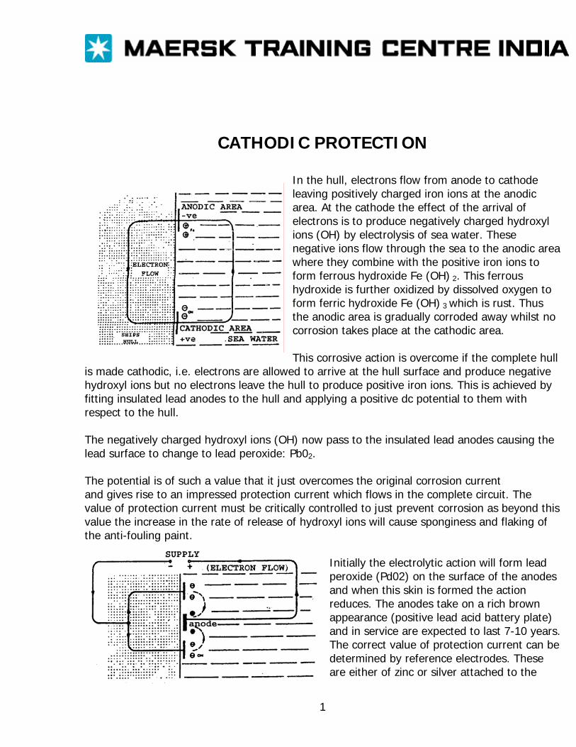
CATHODIC PROTECTION
In the hull, electrons flow from anode to cathode leaving positively charged iron ions at the anodic area. At the cathode the effect of the arrival of electrons is to produce negatively charged hydroxyl ions (OH) by electrolysis of sea water. These negative ions flow through the sea to the anodic area where they combine with the positive iron ions to form ferrous hydroxide Fe (OH) 2. This ferrous hydroxide is further oxidized by dissolved oxygen to form ferric hydroxide Fe (OH) 3 which is rust. Thus the anodic area is gradually corroded away whilst no corrosion takes place at the cathodic area. This corrosive action is overcome if the complete hull
is made cathodic, i.e. electrons are allowed to arrive at the hull surface and produce negative hydroxyl ions but no electrons leave the hull to produce positive iron ions. This is achieved by fitting insulated lead anodes to the hull and applying a positive dc potential to them with respect to the hull. The negatively charged hydroxyl ions (OH) now pass to the insulated lead anodes causing the lead surface to change to lead peroxide: Pb02. The potential is of such a value that it just overcomes the original corrosion current and gives rise to an impressed protection current which flows in the complete circuit. The value of protection current must be critically controlled to just prevent corrosion as beyond this value the increase in the rate of release of hydroxyl ions will cause sponginess and flaking of the anti-fouling paint.
Initially the electrolytic action will form lead peroxide (Pd02) on the surface of the anodes and when this skin is formed the action reduces. The anodes take on a rich brown appearance (positive lead acid battery plate) and in service are expected to last 7-10 years. The correct value of protection current can be determined by reference electrodes. These are either of zinc or silver attached to the
1
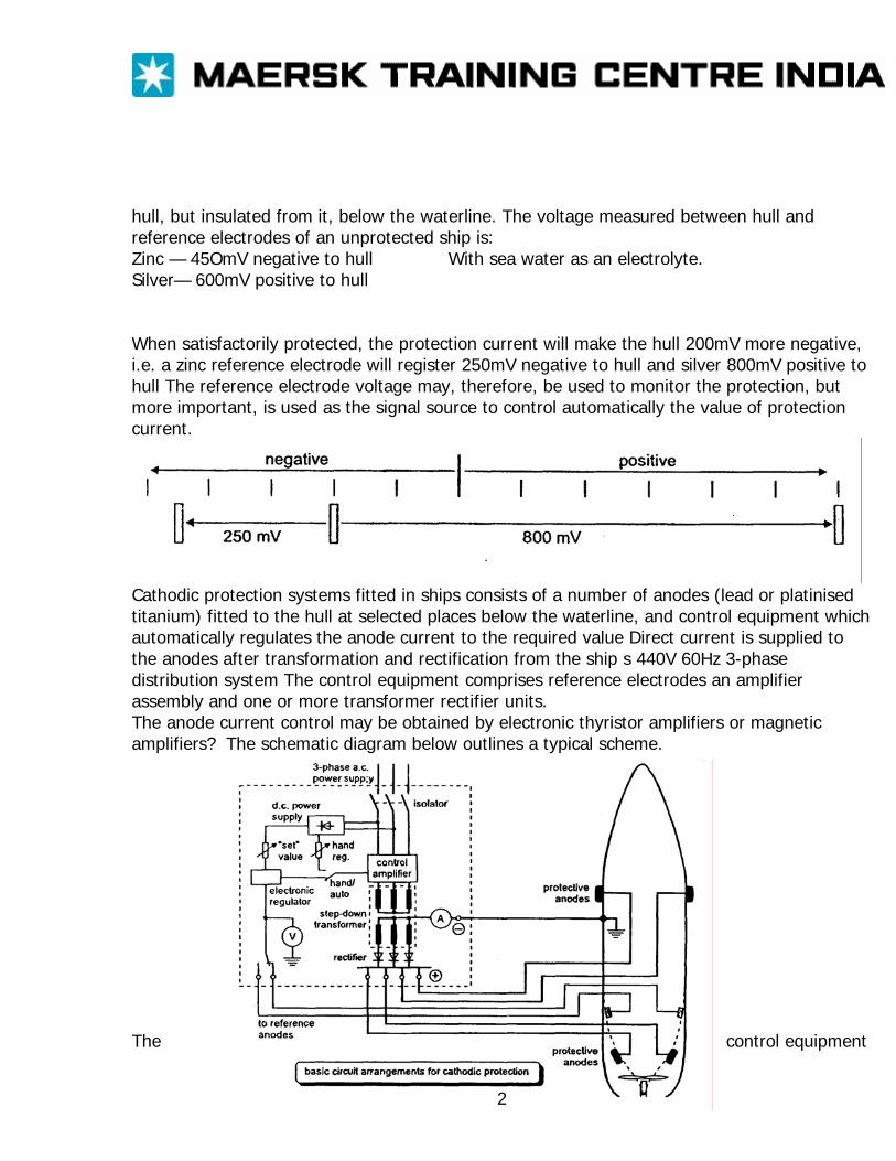
hull, but insulated from it, below the waterline. The voltage measured between hull and reference electrodes of an unprotected ship is: Zinc — 45OmV negative to hull With sea water as an electrolyte. Silver— 600mV positive to hull When satisfactorily protected, the protection current will make the hull 200mV more negative, i.e. a zinc reference electrode will register 250mV negative to hull and silver 800mV positive to hull The reference electrode voltage may, therefore, be used to monitor the protection, but more important, is used as the signal source to control automatically the value of protection current.
Cathodic protection systems fitted in ships consists of a number of anodes (lead or platinised titanium) fitted to the hull at selected places below the waterline, and control equipment which automatically regulates the anode current to the required value Direct current is supplied to the anodes after transformation and rectification from the ship s 440V 60Hz 3-phase distribution system The control equipment comprises reference electrodes an amplifier assembly and one or more transformer rectifier units. The anode current control may be obtained by electronic thyristor amplifiers or magnetic amplifiers? The schematic diagram below outlines a typical scheme. The control equipment
2

automatically monitors the size of anode current required which will vary with the ship’s speed, water temperature and salinity, condition of paint work etc. Typical anode current densities range from 1 OmA/m2 to 4OmA/m2 for protection of painted surfaces and 100 to 150 mNm2 for bare surfaces. The total controller current for a hull in good condition may be as low as 20A. Maximum controller outputs may be up to about 600A at 8V. Cathodic protection does not appear to deter molluscular growth on the ship’s hull, so a topcoat of anti-foul (poisonous) paint is still necessary.
3
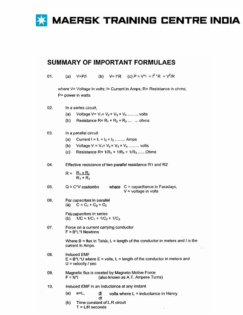
1
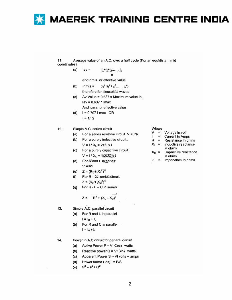
2
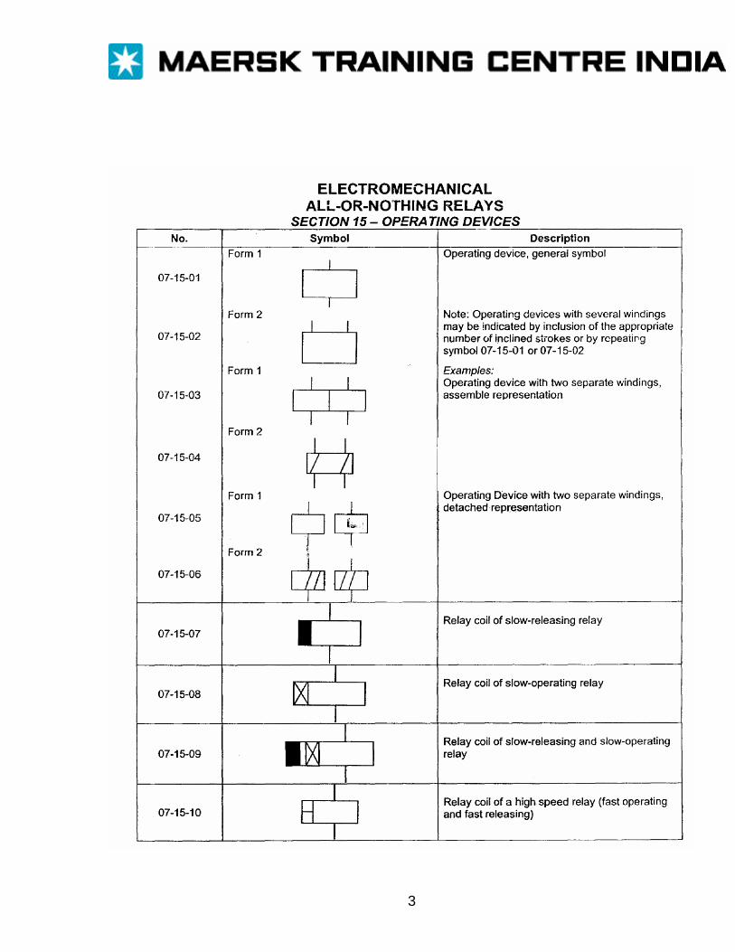
3
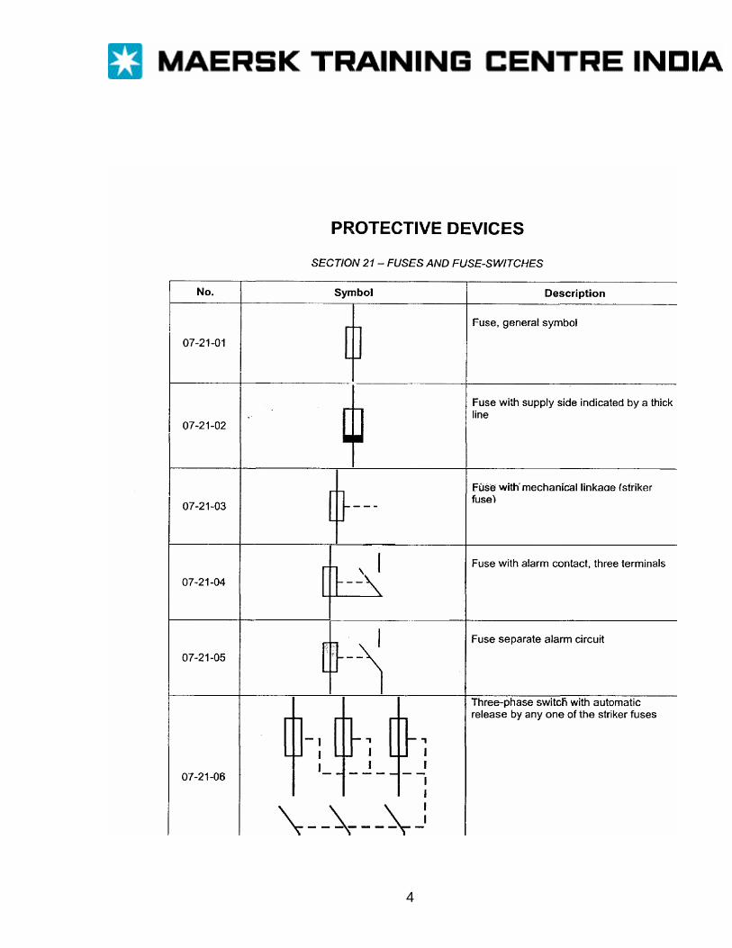
4
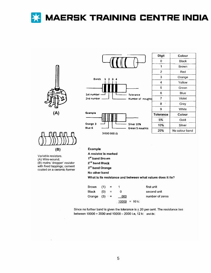
5


![EPISODE 02 [0:00:00.0] JM - Software Engineering Dailysoftwareengineeringdaily.com/wp-content/uploads/2017/04/... · 2017-04-27 · SEDT 02 Transcript EPISODE 02 [0:00:00.0] JM: Brendan](https://img.pdfslide.us/doc/110x75/5f76537838944d1b91780940/episode-02-000000-jm-software-engineering-dailysoft-2017-04-27-sedt-02.jpg)