Embed Size (px)
Citation preview
357
C H A P T E R 1 9
Engine Reassembly and Break-In
Learning Objectives Key Terms
After studying this chapter, you will be able to:
• Summarize the steps in reassembling L-head and overhead valve engines.
• Explain how crankshafts and camshafts should be reinstalled.
• Summarize the steps in reassembling a piston and rod assembly and installing rings.
• Explain the purpose of ring end gap.
• Describe methods of adjusting crankshaft endplay.
• Summarize what happens during piston ring wear-in.
assembly lubebearing crushbearing spread
break-indampening coils
IntroductionAfter the engine has been disassembled and all
the parts have been cleaned, inspected, and recon-ditioned as needed, the engine must be properly reassembled. Always reassemble the engine in a clean work area. If dirt or other abrasives get into the engine during reassembly, it can undo all of the hard work that went into the engine rebuild.
Have all of the necessary repair parts, supplies, and instructions handy and well organized. Read through the manufacturer’s instructions for reas-sembling the engine and be sure you understand them before beginning. The instructions provided in this chapter are general in nature, and may not apply to the engine you are servicing.
Reinstalling Internal Engine Components
The steps followed to reassemble an engine are essentially the reverse of the steps used to disas-semble it. Begin by making sure that all bearings or bushings are properly installed in the crankcase and crankcase cover. Next, install replacement oil seals in the crankcase and crankcase cover. Apply sealant around the outside of the shell of the seal before pressing it in place. Often, seals can be replaced by tapping them into the bore with a seal driver. If a seal driver is not available, a socket of the appropriate size can be used. See Figure 19-1.
If the engine is equipped with a centrifugal gov-ernor, the governor shaft should be installed next.
This sample chapter is for review purposes only. Copyright © The Goodheart-Willcox Co., Inc. All rights reserved.
358 Section 4 Engine Service
Installing Valves (L-Head Engine)If the engine being serviced is an L-head engine,
engine reassembly should continue with reinstal-lation of the valves. If an overhead valve engine is being reassembled, the valves are located in the cyl-inder head rather than the block. Overhead valves can be reinstalled toward the end of the reassembly process. Overhead valve installation is covered in a separate section later in this chapter.
After the valves and seats have been properly reconditioned, apply valve guide lubricant to the valve stems and then place each valve in its respec-tive guide. Use a valve spring compressor to com-press the spring and, then, install the keepers. See Figure 19-2.
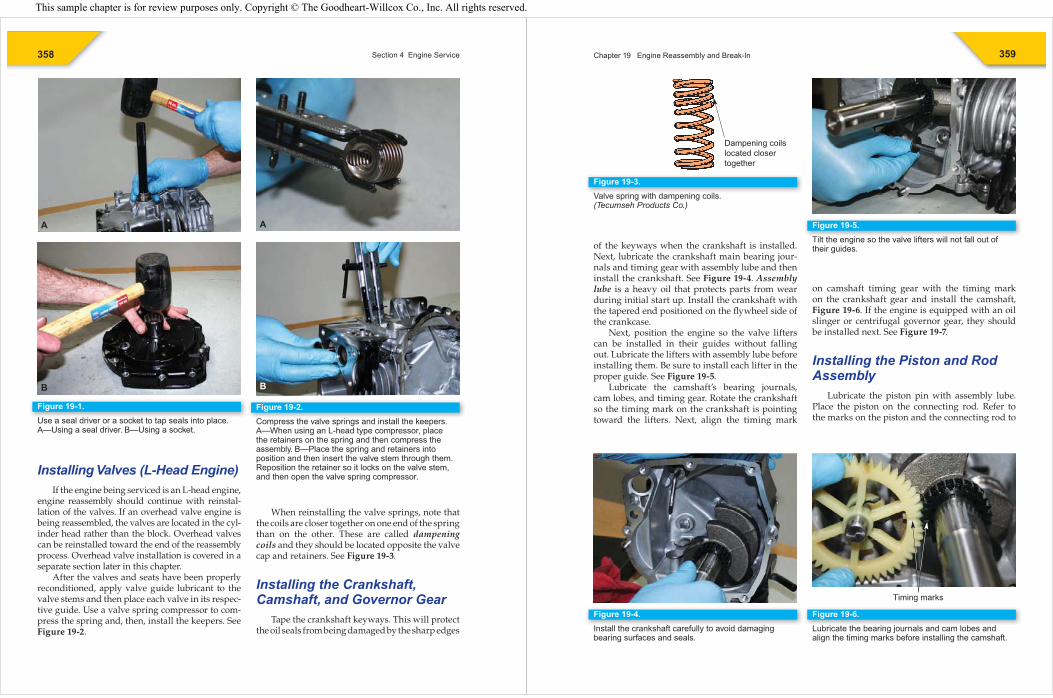
When reinstalling the valve springs, note that the coils are closer together on one end of the spring than on the other. These are called dampening coils and they should be located opposite the valve cap and retainers. See Figure 19-3.
Installing the Crankshaft, Camshaft, and Governor Gear
Tape the crankshaft keyways. This will protect the oil seals from being damaged by the sharp edges
Figure 19-1.Use a seal driver or a socket to tap seals into place. A—Using a seal driver. B—Using a socket.
A
B
Figure 19-2.Compress the valve springs and install the keepers. A—When using an L-head type compressor, place the retainers on the spring and then compress the assembly. B—Place the spring and retainers into position and then insert the valve stem through them. Reposition the retainer so it locks on the valve stem, and then open the valve spring compressor.
A
B
359Chapter 19 Engine Reassembly and Break-In
of the keyways when the crankshaft is installed. Next, lubricate the crankshaft main bearing jour-nals and timing gear with assembly lube and then install the crankshaft. See Figure 19-4. Assembly lube is a heavy oil that protects parts from wear during initial start up. Install the crankshaft with the tapered end positioned on the fl ywheel side of the crankcase.
Next, position the engine so the valve lifters can be installed in their guides without falling out. Lubricate the lifters with assembly lube before installing them. Be sure to install each lifter in the proper guide. See Figure 19-5.
Lubricate the camshaft’s bearing journals, cam lobes, and timing gear. Rotate the crankshaft so the timing mark on the crankshaft is pointing toward the lifters. Next, align the timing mark
on camshaft timing gear with the timing mark on the crankshaft gear and install the camshaft, Figure 19-6. If the engine is equipped with an oil slinger or centrifugal governor gear, they should be installed next. See Figure 19-7.
Installing the Piston and Rod Assembly
Lubricate the piston pin with assembly lube. Place the piston on the connecting rod. Refer to the marks on the piston and the connecting rod to
Figure 19-3.Valve spring with dampening coils.(Tecumseh Products Co.)
Dampening coilslocated closertogether
Figure 19-4.Install the crankshaft carefully to avoid damaging bearing surfaces and seals.
Figure 19-5.Tilt the engine so the valve lifters will not fall out of their guides.
Figure 19-6.Lubricate the bearing journals and cam lobes and align the timing marks before installing the camshaft.
Timing marks
This sample chapter is for review purposes only. Copyright © The Goodheart-Willcox Co., Inc. All rights reserved.
360 Section 4 Engine Service
ensure the piston is installed in the proper direc-tion. Push the piston pin through the piston and connecting rod and secure it with new retainers. See Figure 19-8.
Checking Ring End GapThe inside diameter of a piston ring is always
made smaller than the piston’s diameter. This being the case, each ring must be expanded to get it over the piston head and into the ring groove. The amount of end gap is critical and should match the manufacturer’s specifi cations. As a rule of thumb, however, allow .004″ of end gap for every inch of cylinder diameter. For example, the minimum end gap for a 2.5″ cylinder is .010″.
Too much end gap will allow the gases to leak between the ring ends. Too little gap is even more serious. When the rings heat up in service, they will expand and close up. If the rings continue to heat and expand, they will break and score the cyl-inder wall.
To measure ring end gap, place the ring in the cylinder. Then, turn a piston upside down and push the ring to the lower end of the cylinder. When the ring reaches the proper depth, remove the piston.
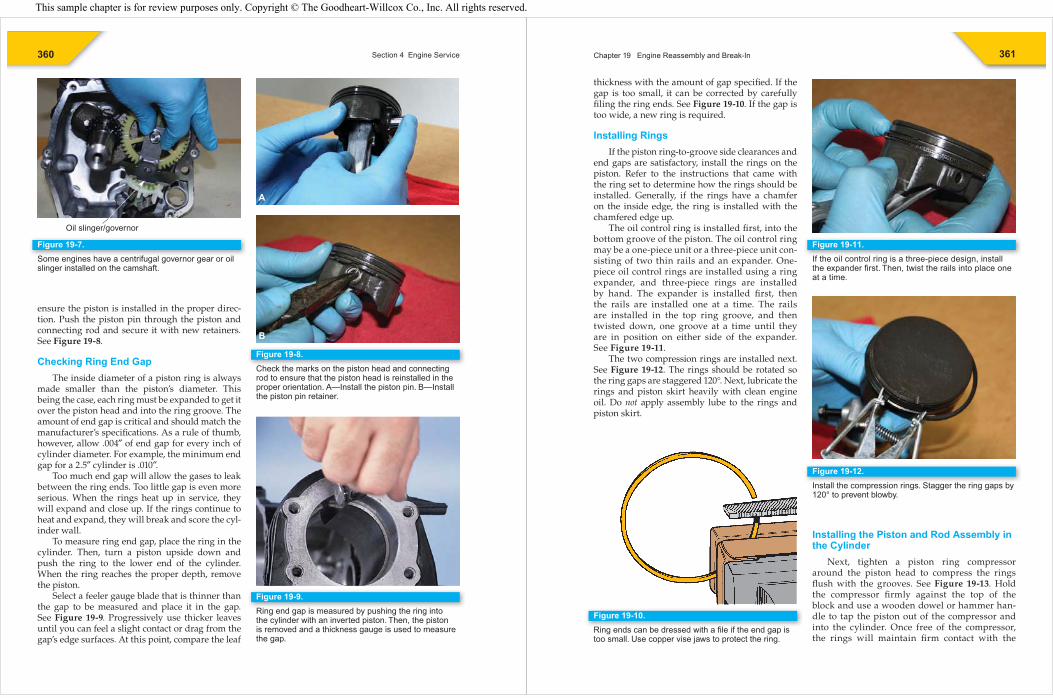
Select a feeler gauge blade that is thinner than the gap to be measured and place it in the gap. See Figure 19-9. Progressively use thicker leaves until you can feel a slight contact or drag from the gap’s edge surfaces. At this point, compare the leaf
Figure 19-7.Some engines have a centrifugal governor gear or oil slinger installed on the camshaft.
Oil slinger/governor
Figure 19-8.Check the marks on the piston head and connecting rod to ensure that the piston head is reinstalled in the proper orientation. A—Install the piston pin. B—Install the piston pin retainer.
A
B
Figure 19-9.Ring end gap is measured by pushing the ring into the cylinder with an inverted piston. Then, the piston is removed and a thickness gauge is used to measure the gap.
361Chapter 19 Engine Reassembly and Break-In
thickness with the amount of gap specifi ed. If the gap is too small, it can be corrected by carefully fi ling the ring ends. See Figure 19-10. If the gap is too wide, a new ring is required.
Installing RingsIf the piston ring-to-groove side clearances and
end gaps are satisfactory, install the rings on the piston. Refer to the instructions that came with the ring set to determine how the rings should be installed. Generally, if the rings have a chamfer on the inside edge, the ring is installed with the chamfered edge up.
The oil control ring is installed fi rst, into the bottom groove of the piston. The oil control ring may be a one-piece unit or a three-piece unit con-sisting of two thin rails and an expander. One- piece oil control rings are installed using a ring expander, and three-piece rings are installed by hand. The expander is installed fi rst, then the rails are installed one at a time. The rails are installed in the top ring groove, and then twisted down, one groove at a time until they are in position on either side of the expander. See Figure 19-11.
The two compression rings are installed next. See Figure 19-12. The rings should be rotated so the ring gaps are staggered 120°. Next, lubricate the rings and piston skirt heavily with clean engine oil. Do not apply assembly lube to the rings and piston skirt.
Installing the Piston and Rod Assembly in the Cylinder
Next, tighten a piston ring compressor around the piston head to compress the rings fl ush with the grooves. See Figure 19-13. Hold the compressor fi rmly against the top of the block and use a wooden dowel or hammer han-dle to tap the piston out of the compressor and into the cylinder. Once free of the compressor, the rings will maintain fi rm contact with the
Figure 19-10.Ring ends can be dressed with a fi le if the end gap is too small. Use copper vise jaws to protect the ring.
Figure 19-11.If the oil control ring is a three-piece design, install the expander fi rst. Then, twist the rails into place one at a time.
Figure 19-12.Install the compression rings. Stagger the ring gaps by 120° to prevent blowby.
This sample chapter is for review purposes only. Copyright © The Goodheart-Willcox Co., Inc. All rights reserved.
362 Section 4 Engine Service
Installing Insert-Type Rod BearingsThe diameter across the parting surfaces of
insert bearing halves is slightly larger than the diameter across the curve machined into the rod and rod cap. This condition is called bearing spread. The correct amount of bearing spread gives tight insert-to-bore contact around the entire bearing and provides support and alignment. It also helps to carry heat away through the rod and bearing cap and holds the bearing in place during assembly.
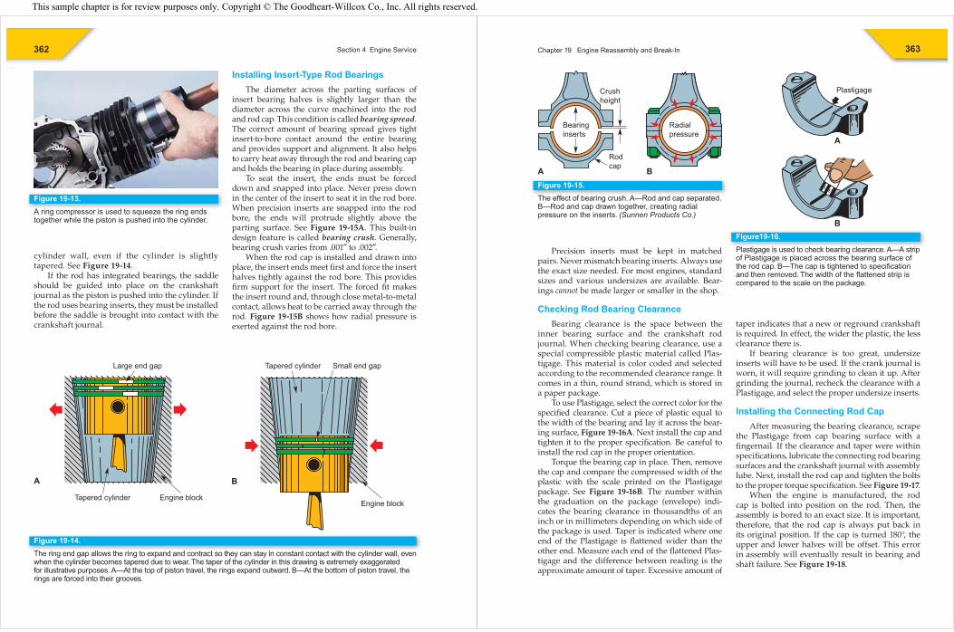
To seat the insert, the ends must be forced down and snapped into place. Never press down in the center of the insert to seat it in the rod bore. When precision inserts are snapped into the rod bore, the ends will protrude slightly above the parting surface. See Figure 19-15A. This built-in design feature is called bearing crush. Generally, bearing crush varies from .001″ to .002″.
When the rod cap is installed and drawn into place, the insert ends meet fi rst and force the insert halves tightly against the rod bore. This provides fi rm support for the insert. The forced fi t makes the insert round and, through close metal-to-metal contact, allows heat to be carried away through the rod. Figure 19-15B shows how radial pressure is exerted against the rod bore.
Figure 19-13.A ring compressor is used to squeeze the ring ends together while the piston is pushed into the cylinder.
Figure 19-14.The ring end gap allows the ring to expand and contract so they can stay in constant contact with the cylinder wall, even when the cylinder becomes tapered due to wear. The taper of the cylinder in this drawing is extremely exaggerated for illustrative purposes. A—At the top of piston travel, the rings expand outward. B—At the bottom of piston travel, the rings are forced into their grooves.
Large end gap
Tapered cylinder
Tapered cylinder Small end gap
Engine block
A B
Engine block
cylinder wall, even if the cylinder is slightly tapered. See Figure 19-14.
If the rod has integrated bearings, the saddle should be guided into place on the crankshaft journal as the piston is pushed into the cylinder. If the rod uses bearing inserts, they must be installed before the saddle is brought into contact with the crankshaft journal.
363Chapter 19 Engine Reassembly and Break-In
Precision inserts must be kept in matched pairs. Never mismatch bearing inserts. Always use the exact size needed. For most engines, standard sizes and various undersizes are available. Bear-ings cannot be made larger or smaller in the shop.
Checking Rod Bearing ClearanceBearing clearance is the space between the
inner bearing surface and the crankshaft rod journal. When checking bearing clearance, use a special compressible plastic material called Plas-tigage. This material is color coded and selected according to the recommended clearance range. It comes in a thin, round strand, which is stored in a paper package.
To use Plastigage, select the correct color for the specifi ed clearance. Cut a piece of plastic equal to the width of the bearing and lay it across the bear-ing surface, Figure 19-16A. Next install the cap and tighten it to the proper specifi cation. Be careful to install the rod cap in the proper orientation.
Torque the bearing cap in place. Then, remove the cap and compare the compressed width of the plastic with the scale printed on the Plastigage package. See Figure 19-16B. The number within the graduation on the package (envelope) indi-cates the bearing clearance in thousandths of an inch or in millimeters depending on which side of the package is used. Taper is indicated where one end of the Plastigage is fl attened wider than the other end. Measure each end of the fl attened Plas-tigage and the difference between reading is the approximate amount of taper. Excessive amount of
taper indicates that a new or reground crankshaft is required. In effect, the wider the plastic, the less clearance there is.
If bearing clearance is too great, undersize inserts will have to be used. If the crank journal is worn, it will require grinding to clean it up. After grinding the journal, recheck the clearance with a Plastigage, and select the proper undersize inserts.
Installing the Connecting Rod CapAfter measuring the bearing clearance, scrape
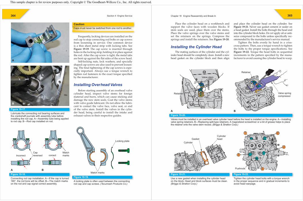
the Plastigage from cap bearing surface with a fi ngernail. If the clearance and taper were within specifi cations, lubricate the connecting rod bearing surfaces and the crankshaft journal with assembly lube. Next, install the rod cap and tighten the bolts to the proper torque specifi cation. See Figure 19-17.
When the engine is manufactured, the rod cap is bolted into position on the rod. Then, the assembly is bored to an exact size. It is important, therefore, that the rod cap is always put back in its original position. If the cap is turned 180°, the upper and lower halves will be offset. This error in assembly will eventually result in bearing and shaft failure. See Figure 19-18.
Figure 19-15.The effect of bearing crush. A—Rod and cap separated. B—Rod and cap drawn together, creating radial pressure on the inserts. (Sunnen Products Co.)
Radialpressure
A B
Bearinginserts
Crushheight
Rodcap
Figure19-16.Plastigage is used to check bearing clearance. A—A strip of Plastigage is placed across the bearing surface of the rod cap. B—The cap is tightened to specifi cation and then removed. The width of the fl attened strip is compared to the scale on the package.
Plastigage
A
B
This sample chapter is for review purposes only. Copyright © The Goodheart-Willcox Co., Inc. All rights reserved.
364 Section 4 Engine Service
Caps must never be switched from one rod to another.
Frequently, locking devices are installed on the rod cap to stop connecting rod bolts or cap screws from loosening in service. One common device is a thin sheet metal strip with locking tabs. See Figure 19-19. The cap screw is inserted through holes in the locking strip, holding it in place against the rod. After the cap screw is tight, the metal tabs are bent up against the fl at sides of the screw head.
Self-locking nuts, lock washers, and specially shaped cap screws are also used to prevent loosen-ing. The fi nal tightening of the cap screws is espe-cially important. Always use a torque wrench to tighten rod fasteners to the exact torque specifi ed by the manufacturer.
Installing Overhead ValvesBefore starting assembly of an overhead valve
cylinder head, inspect valve stems for foreign material and burrs, which can cause sticking and damage the new stem seals. Coat the valve stems with valve guide lubricant. Do not allow the lubri-cant to contact the valve face, valve seat, or end of the valve stem. Install the valves in the cylin-der head, being careful to install the intake and exhaust valves in their respective guides.
CautionCCCaaappss mmmuusst nneeveer bee swiitched from one rod to another.CCC t b iit h d f d t th
Figure 19-17.Lubricate the connecting rod bearing surfaces and the crankshaft journals with assembly lube before installing the rod cap. A—Assembly lube being applied to rod cap. B—Rod cap installed on rod.
A
B
Figure 19-18.Connecting rod cap installation. A—If the cap is turned 180°, the rod bore will be offset. B—The match marks on the rod and cap signal correct assembly.
A B
Incorrect correctCapreversed
Matchmarks
Figure 19-19.A locking plate is often used between the connecting rod cap and cap screws. (Tecumseh Products Co.)
Match marks
Locking plate
365Chapter 19 Engine Reassembly and Break-In
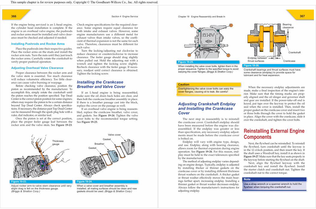
Place the cylinder head on a workbench and support the valve faces with wooden blocks. If stem seals are used, place them over the stems. Place the valve springs over the valve stems and set the retainers on the springs. Compress the springs and install the retainers. See Figure 19-20.
Installing the Cylinder HeadThe mating surfaces of the cylinder and the cyl-
inder head should be completely clean. Install a new head gasket on the cylinder block and then align
and place the cylinder head on the cylinder. See Figure 19-21. Never use gasket cement or sealer on a head gasket. Install the bolts through the head and into the cylinder block holes. Do not apply oil or anti-seize compound to the bolts unless specifi cally rec-ommended by the manufacturer’s service manual.
Tighten the bolts evenly by hand in a criss-cross pattern. Then, use a torque wrench to tighten the bolts to the proper torque specifi cations. See Figure 19-22. Torque the head bolts in sequential increments in the pattern specifi ed by the manu-facturer to avoid causing the cylinder head to warp.
Figure 19-20.Valves must be installed in an overhead valve cylinder head before the head is installed on the engine. A—Installing valve spring retainers. B—Replacing split-type retainers. A magnetized screwdriver or a bit of grease helps to place the retainer onto the valve stem recess. (Briggs & Stratton Corp.)
A B
Valve stem
Retainer
Retainer
Valve springcompressor
Figure 19-21.Use a new gasket when installing the cylinder head on the block. Head and block surfaces must be clean. (Briggs & Stratton Corp.)
Cylinder
CylinderheadGasket
Figure 19-22.Tighten the cylinder head bolts with a torque wrench in the proper sequence and in gradual increments to avoid head warpage.
Pushrods
1 4
2
5
3
This sample chapter is for review purposes only. Copyright © The Goodheart-Willcox Co., Inc. All rights reserved.
366 Section 4 Engine Service
If the engine being serviced is an L-head engine, the cylinder head installation is complete. If the engine is an overhead valve engine, the pushrods and rocker arms must be installed and valve clear-ance must be checked and adjusted if needed.
Installing Pushrods and Rocker ArmsPlace the pushrods into their respective guides.
Place the rocker arms on the studs and install the rocker arm nuts. Turn the nuts until they just touch the rocker arms. Carefully rotate the crankshaft to verify proper pushrod operation.
Adjusting Overhead Valve ClearanceProper clearance between the rocker arm and
the valve stem is essential. Too much clearance will reduce volumetric effi ciency. Too little clear-ance can cause valve burning or warpage.
Before checking valve clearance, position the piston as recommended by the manufacturer. To accomplish this, simply rotate the crankshaft until the piston reaches the position specifi ed. Top Dead Center is the correct piston position for some engines; others may require the piston to be a certain distance beyond Top Dead Center. Always check specifi ca-tions. If necessary, the distance past Top Dead Center can be measured through the spark plug hole with a ruler, dial indicator, or similar tool.
Once the piston is set at the correct position, place the proper feeler gauge leaf between the rocker arm and the valve stem. See Figure 19-23.
Check engine specifi cations for the required clear-ance. Some engines require equal clearance for both intake and exhaust valves. However, some engine manufacturers use a different metal for exhaust valves than intake valves, so the coeffi -cient of thermal expansion is not the same for each valve. Therefore, clearances must be different for each valve.
Turn the locking/adjusting nut clockwise to reduce clearance or counterclockwise to increase clearance. The feeler gauge should drag slightly when pulled out. Hold the adjusting nut with a wrench and tighten the locking screw slightly. Recheck clearance with the feeler gauge. If neces-sary, readjust until correct clearance is obtained. Tighten the locking screw.
Installing the Crankcase Breather and Valve Cover
If an L-head engine is being reassembled, make sure the oil drain back holes are clear, and then bolt the crankcase breather assembly in place. If there is a breather passage cast into the block, replace the cover on the passage as well.
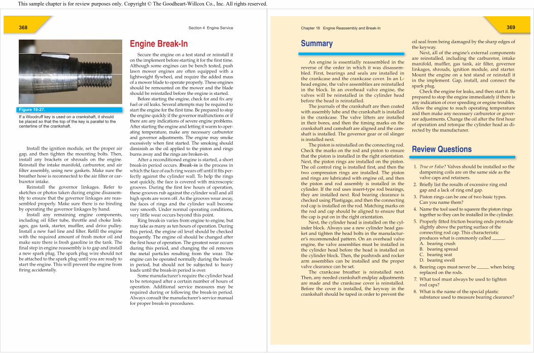
If an overhead valve engine is being reassem-bled, replace the crankcase breather, valve cover, and gaskets. See Figure 19-24. Tighten the valve cover bolts to the recommended torque setting. See Figure 19-25.
Figure 19-23.Adjust rocker arm-to-valve stem clearance until very slight drag is felt on the thickness gauge.(Briggs & Stratton Corp.)
Thicknessgauge
Figure 19-24.When a valve cover and breather assembly is installed, all mating surfaces should be clean and new gaskets should be used. (Briggs & Stratton Corp.)
GasketBreather
Gasket
Valve cover
367Chapter 19 Engine Reassembly and Break-In
Overtightening the valve cover bolts can warp the cover fl anges, causing oil to leak. Be careful!
Adjusting Crankshaft Endplay and Installing the Crankcase Cover
The next step in reassembly is to reinstall the crankcase cover. Crankshaft endplay should have been measured before the engine was dis-assembled. If the endplay was greater or less than specifi cation, any necessary endplay adjust-ments must be made before the crankcase cover is bolted on.
Endplay will vary with engine type, design, and use. Endplay, along with bearing clearance, allows room for thermal expansion during engine operation. See Figure 19-26. For this reason, end-play must be held to the exact tolerances specifi ed by the manufacturer.
The method of adjusting endplay varies depend-ing on engine design. Typically, endplay is adjusted by installing thicker or thinner gaskets on the crankcase cover or by installing different thickness thrust washers on the crankshaft. A thicker gasket or thrust washer effectively moves the main bear-ings farther apart, increasing endplay. Installing a thinner gasket or thrust washer decreases endplay. Always follow the manufacturer’s instructions for adjusting endplay.
CautionOOOvvveerttighteeningg thhe valvee cover bolts can warp theccoooovveerr flflanggees,, caaaussing ooil to leak. Be careful!OOO tti ht i thh l b lt th When the necessary endplay adjustments are
made, make a fi nal inspection of the engine’s inte-rior. Make sure that the timing marks are prop-erly aligned and the oil slinger and governor shaft and gear are installed. If the power-take-off end is keyed, put tape over the keyway to protect the oil seal when the cover is installed. Then, install the proper gasket on the crankcase cover and insert two or three bolts through the cover to hold the gasket in place. Align the cover with the crankcase, slide it over the crankshaft, and tighten the cover bolts.
Reinstalling External Engine Components
Next, the fl ywheel can be reinstalled. To reinstall the fl ywheel, turn crankshaft until the keyway is in the 12 o’clock position, and then insert the key. If the shaft uses a Woodruff key, install it as shown in Figure 19-27. Make sure that the key seats properly in the keyway before starting the fl ywheel on the shaft.
Next, align the fl ywheel keyway with the crankshaft key and install the fl ywheel. Install the starter clutch and crankshaft nut. Tighten the crankshaft nut to the correct torque.
Use a strap wrench or a spanner wrench to hold the fl ywheel when torquing the crankshaft nut.
NoteUUUsse aa stttrapp wwrench or a sppanner wrench to hold the flflyywhhheell whhenn torrquing thee crankshaft nut.
Figure 19-25.When installing the valve cover bolts, tighten them in the proper sequence. Tighten to the specifi ed torque to avoid warping the cover fl anges. (Briggs & Stratton Corp.)
1 4
3 2
Figure 19-26.Crankshaft bearings and thrust surfaces must have some clearance (endplay) to provide space for lubricant and for heat expansion.
Crankshaft
Crankcase
Bearingclearance
Endplay betweenthrust surfaces
This sample chapter is for review purposes only. Copyright © The Goodheart-Willcox Co., Inc. All rights reserved.
368 Section 4 Engine Service
Install the ignition module, set the proper air gap, and then tighten the mounting bolts. Then, install any brackets or shrouds on the engine. Reinstall the intake manifold, carburetor, and air fi lter assembly, using new gaskets. Make sure the breather hose is reconnected to the air fi lter or car-buretor intake.
Reinstall the governor linkages. Refer to sketches or photos taken during engine disassem-bly to ensure that the governor linkages are reas-sembled properly. Make sure there is no binding by operating the governor linkages by hand.
Install any remaining engine components, including oil fi ller tube, throttle and choke link-ages, gas tank, starter, muffl er, and drive pulley. Install a new fuel line and fi lter. Refi ll the engine with the required amount of fresh motor oil and make sure there is fresh gasoline in the tank. The fi nal step in engine reassembly is to gap and install a new spark plug. The spark plug wire should not be attached to the spark plug until you are ready to start the engine. This will prevent the engine from fi ring accidentally.
Engine Break-InSecure the engine on a test stand or reinstall it
on the implement before starting it for the fi rst time. Although some engines can be bench tested, push lawn mower engines are often equipped with a lightweight fl ywheel, and require the added mass of a mower blade to operate properly. These engines should be remounted on the mower and the blade should be reinstalled before the engine is started.
Before starting the engine, check for and fi x any fuel or oil leaks. Several attempts may be required to start the engine for the fi rst time. Be prepared to stop the engine quickly if the governor malfunctions or if there are any indications of severe engine problems. After starting the engine and letting it warm to oper-ating temperature, make any necessary carburetor and governor adjustments. The engine may smoke excessively when fi rst started. The smoking should diminish as the oil applied to the piston and rings burns away and the rings are broken-in.
After a reconditioned engine is started, a short break-in period occurs. Break-in is the process in which the face of each ring wears off until it fi ts per-fectly against the cylinder wall. To help the rings seat quickly, the face is covered with microscopic grooves. During the fi rst few hours of operation, these grooves rub against the cylinder wall and all high spots are worn off. As the grooves wear away, the faces of rings and the cylinder wall become very smooth. Under normal operating conditions, very little wear occurs beyond this point.
Ring break-in varies from engine to engine, but may take as many as ten hours of operation. During this period, the engine oil level should be checked frequently. The engine oil should be changed after the fi rst hour of operation. The greatest wear occurs during this period, and changing the oil removes the metal particles resulting from the wear. The engine can be operated normally during the break-in period, but should not be subjected to heavy loads until the break-in period is over.
Some manufacturer’s require the cylinder head to be retorqued after a certain number of hours of operation. Additional service measures may be required during or following the break-in period. Always consult the manufacturer’s service manual for proper break-in procedures.
Figure 19-27.If a Woodruff key is used on a crankshaft, it should be placed so that the top of the key is parallel to the centerline of the crankshaft.
Summary
An engine is essentially reassembled in the reverse of the order in which it was disassem-bled. First, bearings and seals are installed in the crankcase and the crankcase cover. In an L-head engine, the valve assemblies are reinstalled in the block. In an overhead valve engine, the valves will be reinstalled in the cylinder head before the head is reinstalled.
The journals of the crankshaft are then coated with assembly lube and the crankshaft is installed in the crankcase. The valve lifters are installed in their bores, and then the timing marks on the crankshaft and camshaft are aligned and the cam-shaft is installed. The governor gear or oil slinger is installed next.
The piston is reinstalled on the connecting rod. Check the marks on the rod and piston to ensure that the piston is installed in the right orientation. Next, the piston rings are installed on the piston. The oil control ring is installed fi rst, and then the two compression rings are installed. The piston and rings are lubricated with engine oil, and then the piston and rod assembly is installed in the cylinder. If the rod uses insert-type rod bearings, they are installed next. Rod bearing clearance is checked using Plastigage, and then the connecting rod cap is installed on the rod. Matching marks on the rod and cap should be aligned to ensure that the cap is put on in the right orientation.
Next, the cylinder head is installed on the cyl-inder block. Always use a new cylinder head gas-ket and tighten the head bolts in the manufactur-er’s recommended pattern. On an overhead valve engine, the valve assemblies must be installed in the cylinder head before the head is installed on the cylinder block. Then, the pushrods and rocker arm assemblies can be installed and the proper valve clearance can be set.
The crankcase breather is reinstalled next. Then, any needed crankshaft endplay adjustments are made and the crankcase cover is reinstalled. Before the cover is installed, the keyway in the crankshaft should be taped in order to prevent the
369Chapter 19 Engine Reassembly and Break-In
oil seal from being damaged by the sharp edges of the keyway.
Next, all of the engine’s external components are reinstalled, including the carburetor, intake manifold, muffl er, gas tank, air fi lter, governor linkages, shrouds, ignition module, and starter. Mount the engine on a test stand or reinstall it in the implement. Gap, install, and connect the spark plug.
Check the engine for leaks, and then start it. Be prepared to stop the engine immediately if there is any indication of over speeding or engine troubles. Allow the engine to reach operating temperature and then make any necessary carburetor or gover-nor adjustments. Change the oil after the fi rst hour of operation and retorque the cylinder head as di-rected by the manufacturer.
Review Questions
1. True or False? Valves should be installed so the dampening coils are on the same side as the valve caps and retainers.
2. Briefl y list the results of excessive ring end gap and a lack of ring end gap.
3. Piston rings can be one of two basic types. Can you name them?
4. Name the tool used to squeeze the piston rings together so they can be installed in the cylinder.
5. Properly fi tted friction bearing ends protrude slightly above the parting surface of the connecting rod cap. This characteristic produces what is commonly called .
A. bearing crush B. bearing spread C. bearing seat D. bearing swell
6. Bearing caps must never be when being replaced on the rods.
7. What tool must always be used to tighten rod caps?
8. What is the name of the special plastic substance used to measure bearing clearance?
This sample chapter is for review purposes only. Copyright © The Goodheart-Willcox Co., Inc. All rights reserved.
370 Section 4 Engine Service
9. When new or reconditioned valves are being installed in guides, what should be placed on the valve stems fi rst?
10. How is valve clearance checked on an overhead valve engine?
11. Why should valve cover screws never be tightened excessively?
12. What two methods are typically used to adjust crankshaft endplay?
13. Why should lawn mower engines be reinstalled in the equipment before they are test run?
14. True or False? Engine oil should be changed after the fi rst hour of operation following an engine overhaul.
15. Some manufacturers require the to be retorqued after a certain number of hours of operation following an engine overhaul.
Suggested Activities
1. Replace oil seals in the crankcase. 2. Time the camshaft to the crankshaft. 3. Measure crankshaft bearing clearances with
Plastigage and telescoping gauges. 4. Install new main and rod bearing inserts.
Observe rules of cleanliness and torque rod bolts to specifi ed value.
5. Using an old ring, demonstrate the method of dressing ring ends with a fi le to increase ring end gap.
6. Replace piston rings with a ring expander. 7. Using ring compressor, replace a
reconditioned piston assembly in the cylinder. 8. Adjust valve clearances in an overhead valve
assembly.
371Chapter 19 Engine Reassembly and Break-In
Small gas engines are used in a wide range of construction equipment, such as this power tamper.(Christina Richards/Shutterstock)
This sample chapter is for review purposes only. Copyright © The Goodheart-Willcox Co., Inc. All rights reserved.


![Chapter IX Measures on Fractalsjswlamb/M345PA46/[B] chap IX...332 Chapter IX Measures on Fractals Figure IX.247. The Random Iteration Algo-rithm, Program 1 in Chap-ter III, is applied](https://img.pdfslide.us/doc/110x75/5e523483009e794eb04a4a25/chapter-ix-measures-on-fractals-jswlambm345pa46b-chap-ix-332-chapter-ix-measures.jpg)