Embed Size (px)
DESCRIPTION
check valve
Citation preview

Check Valves 91
CHECK VALVE Check valves are also described as refl ux, non-return, back pressure, retaining and clack valves. In some areas of usage the term ‘refl ux’ is reserved for the swing disk type of valve and the description ‘check’ is largely associated with the lifting disk type of valve. Current British Standards use the term ‘check valves’ and this includes both swing and lift types.
The purpose of a check valve is to permit flow in one direction and to prevent it in the reverse direction. Commonly such valves are automatic in operation, the pressure of the fl uid fl owing in one direction holding the valve disk open and reverse fl ow, together with the weight of the disk, acting to seat the disk and so cut off the fl ow.
Most check valves are based on either the swing concept or the lift concept. There are many variants and some of the more commonly used of these are referred to in the following. A brief description is also given of a new concept in this fi eld, the cone and diaphragm check valve.
Swing Check ( Conventional) In this design (Fig. 1) a hinged, gatelike disk is free to swing against a body seating face which is tilted. To ensure that the disk takes up a satisfactory seating position at all times, the disk to hinge connection is designed so that the disk has suffi cient freedom to swivel and make true and full contact with the body seat. Disks may be all metal or may be fi tted with leather, rubber, or compostion facings, depending on the nature of the service. In the fully open position, there is little obstruction to fl ow in a swing type chack valve and consequently the pressure drop across the valve is relatively small.
Swing Check with Outside Lever and Weight In this arrangement (Fig. 2), the disk hinge pin is extended through the body and fi tted with an outside lever and weight, which can be set in various positions. In the position illustrated, the weight will assist the disk to close quickly once forward fl ow ceases. Quick closing action is desirable in systems where sudden reversals of fl ow may occur and accumulate considerable momentum before an ordinary unweighted valve disk would close. Quick closing minimizes possible damaging shock and disk chatter. The lever and weight may be mounted so that the weight balances or partly balances the weight of the disk. The valve will then be more sensitive to low pressures and velocities.
Swing Check with Shock-free Operation This is the type of swing valve (Fig. 5) in which the design criteria are directed particularly towards the prevention of shock closure in conditions of very rapid reversal of fl ow, for example in the case of discharge by electrically driven centrifugal pumps. Special features are incorporated to achieve valve closure in the shortest possible time combined with low head loss.
Tilting Disk Check A sophisticated design (Fig. 6) of swing check valve in which a specially shaped disk is pivoted at a selected point, instead of being hinged as in the conventional type of swing check valve. The seat faces on the disk and in the body are bevelled and in the closed position the valve resembles a simple ‘lift’ valve with conical seat. Characteristics are low pressure drop at low velocities and, depending on the design, a quick response to fl ow reversal.
Dual Plate Check (Fig. 7) The valve body is cylindrical in shape and the disk is in the form of two semicircular plates attached to a central hinge pin located in the body. The disk plates are acted upon by one or more torsion springs mounted on the hinge and these hold the plates against a flat seating in the body. The pressure of reverse flow on the plates causes the springs to deflect and allow the plates to deflect and allow the plates to move to an open position. Each plate may be acted upon by a spring or springs independently supported. The incorporation of such fea-tures improves plate response when rapid changes of flow rates are experienced and reduces the severity of pressure surges.
Types

Check Valves92
Swing Check with Outside Lever and Quadrant (Fig. 3) The lever has a drilled hole and a locking pin fastens the lever to a quadrant, thereby holding the valve disk in the open position. Used mainly to assist in line pressure testing.
Swing Check with Fusible Link (Fig. 4) The disk is held in the open position by means of a fusible link attached to the lever. The fusible link has a predeter-mined melting point and the valve is used mainly as a fi re control device.
Lift Check (Fig. 8) The disk sits on a seat face provided on a horizontal bridge wall across the valve body, rather as in a globe valve except that in this case the disk is free to rise. Flow pressure lifts the disk from its seat and back flow, or no flow, causes the disk to drop back on to the seat and so shut off the flow. The disk is usually guided in both the body seat opening and the body cap but sometimes within the seat opening only. For some applications, a spring may be fitted above the disk to ensure that the valve is normallyclosed.
Cover
Cover Gasket
Cover Bolt
Hinge Pin
Hinge
Disk
Body Seat Ring
Body
Fig. 1. Typical swing check valve
Fig. 3. Swing Check valve with outside lever and quadrant
Fig. 4. Swing check valve with fusible link for holding open
Fig. 2. Swing check valve with outside lever and weight

Check Valves 93
Types of Valves Cone and Diaphragm Check This is a modern development (Fig. 11) and a new concept in the fi eld of check valves. The essential elements are a stainless steel perforated cone and a fl exible diaphragm of natural or synthetic rubber. Service fl uid passes through holes in the cone and defl ects the rubber diaphragm inwards. As the fl ow increases the diaphragm is progressively defl ected inwards until the valve is fully open. When fl ow is reduced, the diaphragm tends to open outwards to its original shape and when fl ow ceases the diaphragm snap shot, closing the valve. There are no metallic moving parts in the valve, which is extremely lightweight and can be installed in horizontal or vertical pipes even where the fl ow is vertically downwards. Operating temperatures and pressures are limitedto capabilities of the diaphragm material. Sizing of Check Valves Care should be taken to avoid oversizing of conventional swing and lift check valves. To obtain the minimum velocity required to lift the disk to the full open and stable position it may be necessary on some applications to fi t valves smaller in size than the pipe in which they are installed.
Depending on the service conditions, disks may be of all metal construction or may be in the form of a disk holder fi tted with a rubber or composition disk ring. Like the globe valve the fl ow path through a lift check valve follows a twisting course. Consequently, the pressure drop across the valve is greater than in the swing type of check valve where the fl ow is less restricted.
Lift Check with Dashpot In this design (Fig. 9) a dashpot is arranged above the disk so as to provide a cushion effect on services where pulsations in the line may cause an ordinary check valve to hammer.
Ball Check Similar to the normal lift type check valve but utilizing a ball as the disk. The ball is guided in the body cap but free to rise and rotate.
Screw-down Stop and Check Also known as a screw-down non-return (SDNR) valve (Fig. 10). This is a globe type of valve except that the disk is not attached to the screwed stem. The stem is used to regulate the lift of the disk when it is acting as a check valve, or, to hold the disk closed in the same manner as an ordinary globe valve.
Fig. 5. Swing check valve with shock free operation
Fig. 6. Tilting disk check valve with pressure sealed top closure
Fig. 7. Dual plate check valve

Check Valves94
Fig. 8. Typical lift check valve (with composition disk seating ring)
Fig. 9. Lift check valve with dashpot
Fig. 11. Cone and diaphragm check valve
Stem
Cover
Disk
Body
Seat
Type of Check Valve

Check Valves 95
3
4
5
2
1 Corrugated steel gasket for 150lb valves, spiral wound gasket for 300lb & 600lb valves, and
ring joint for 900lb & above valves as an optional for the 600lb valves on customer request.
A hinge and hinge pin provided and mounted so as to permit full movement of the disc.
Standard renewable seal welded seat with satellite 6 while optional screwed-in seat.
Standard swing type disc only in horizontal pipe lines handling liquids.
Normal provision for a drain tapping at location G while additional bosses on customer request.
Check Valve
1
2
4
5
3
2

Check Valves96
Check Valve Material List

Check Valves 97
Check Valve Dimension & Weight
Class 150 Cast Carbon Steel Check Valve
Class 300 Cast Carbon Steel Check Valve

Check Valves98
Class 600 Cast Carbon Steel Check Valve
Class 900 Cast Carbon Steel Check Valve

Check Valves 99
Class 1500 Cast Carbon Steel Check Valve
Class 2500 Cast Carbon Steel Check Valve

Check Valves100
12
543
6
Pressure Seal Check Valve
7
5
3
1
2
6
7
Segmental thrust ring absorb all the thrust applied by the internal pressure.
Thrust ring to provide bearing surface and prevent deformation of the gaskets.
No external leakage hinge pin design.
4 Stainless steel inlay to ensure soundness and corrosion-resistance in the vital body sealing
zone for carbon and alloy steel valves.
Soft Steel gasket seal to provide large contact area for perfect sealing.
Standard swing type disc only used in horizontal pipe lines handling liquids.
A hinge and hinge pin provided and mounted so as to permit full movement of the disc.

Check Valves 101
Pressure Seal Check Valve Material List

Check Valves102
Pressure Seal Check Valve Dimension & Weight
Class 600 Cast Carbon Steel Check Valve
Class 900 Cast Carbon Steel Check Valve

Check Valves 103
Class 1500 Cast Carbon Steel Check Valve
Class 2500 Cast Carbon Steel Check Valve
Pressure Seal Check Valve Dimension & Weight

Check Valves104
1
2
5
4
3
This series SBN check valve has a shorter face-to-face dimension and dual plate design, the end connection options include water type, tug type and double-fl ange type, and are available in size from 2” to 60” and in pressure ratings from ASME class 150 through 2500. A wide range of body and trim materials are optional on customer’s request. Compared to conventional swing check valves, NEWAY’s dual plate check valves have the advantage of zero leakage
toward outside (no bottled or threaded connections), cost savings, they can be installed in any line orientation, superior seal performance, offer minimal line shock, lower pressure loss and zero seatwear. This series of valves are widely used in oil & gas production, petroleum refi ning, petrochemical, pulp & paper, shipbuilding, and other fl uid back fl ow prevention application.
Dual Plate Check Valve
Retainless Body Design. (Patent Protected)
Shock Bumpers
Two independent Torsion Springs
Uninterrupted Gasket Surface
Body Slot Designed to fi t the Hinge Pin
3
4
1
2
5

Check Valves 105
Dual Plate Check Valve Dimension & Weight
Wafer type - ASME Class 150
Wafer type

Check Valves106
Dual Plate Check Valve Dimension & Weight
Lug type - ASME Class 300
Lug type

Check Valves 107
Dual Plate Check Valve Dimension & Weight
Lug type - ASME Class 150
Lug type

Check Valves108
Dual Plate Check Valve Dimension & Weight
Wafer type - ASME Class 900
Wafer type - ASME Class 1500

Check Valves 109
Dual Plate Check Valve Dimension & Weight
Wafer type - ASME Class 600
Wafer type

Check Valves110
Wafer type - ASME Class 300
Dual Plate Check Valve Dimension & Weight
Wafer type

Check Valves 111
Dual Plate Check Valve Dimension & Weight
Lug type - ASME Class 600
Lug type

Check Valves112
Lug type - ASME Class 900
Dual Plate Check Valve Dimension & Weight
Lug type - ASME Class 1500

Check Valves 113
Dual Plate Check Valve Dimension & Weight
Double Flanged type - ASME Class 150
Double fl anged type

Check Valves114
Dual Plate Check Valve Dimension & Weight
Double Flanged type - ASME Class 900
Double Flanged type - ASME Class 600
Double Flanged type - ASME Class 300
Note:1. A = OD 2. B = F to F 3. D = ID 4. E = Minimum ID 5. Yellow part is amened by technical Dept. 6. Above data are origined from Velan cataloge VEL-PQCV-2006

Check Valves 115
Axial Flow Check Valve
This series SA axial fl ow check valve is a streamlined venturl port design and is available in size from 2” to 48” and in pressure rating from ASME class 150 through 2500 and a wide range of body and trim materials for special application requirement. In Neway axial fl ow check valve, the disc is the only moving part to minimize internal wear, and the confi guration of disc, seating and body provides streamlined fl ow path with a venture effect so as to reduce pressure loss as small as possible. The compressed disc springs initiates valve closure as
fl ow slows down and provides quick reaction on fl ow velocity change. These unique design features ensure Neway series SA valves can deliver an effective dynamic reaction under various fl ow deceleration conditions, this design valve can be used in a wide range of critical and demanding service applications, such as fast-reversing reciprocating compressor system or in installations where the check valve must be placed in close proximity to the pump inlet or outlet.
12
5
4
3
6
Integrated rigid casting of valve outer body and inner housing to ensure the safe and no leakage
toward outside.
4
5 Spring subassembly as the most core components to ensure the effective reaction and adjustment
for the change of the fl ow velocity.
Treamlined Venturl Shape Design to ensure fl ow effi ciency and minimize pressure loss.1
Flow Outlet Side Designed to ensure pressure recovery and minimize fl uid turbulence.2
3 Disc with metal seal surface to effectively prevent scratching from lumps in fl ow.
Seat & Flow Inlet Side designed for maximizing fl ow impact on disc and providing streamlined fl ow
to minimize pressure loss.
6

Check Valves116
Axial Flow Check Valve Dimension & Weight
Flanged End - ASME Class 150
Flanged End - ASME Class 300
Long Pattern Short Pattern
Note: Long pattern is a Neway standard dimension
Note: Long pattern is a Neway standard dimension

Check Valves 117
Axial Flow Check Valve Dimension & Weight
Flanged End - ASME Class 400
Long Pattern Short Pattern

Check Valves118
Axial Flow Check Valve Dimension & Weight
Flanged End - ASME Class 600
Flanged End - ASME Class 900
Note: Long pattern is a Neway standard dimension
Note: Long pattern is a Neway standard dimension
Check Valves 119
Axial Flow Check Valve Dimension & Weight
Flanged End - ASME Class 2500
Long Pattern Short Pattern
Flanged End - ASME Class 1500
Note: Long pattern is a Neway standard dimension
Note: Long pattern is a Neway standard dimension
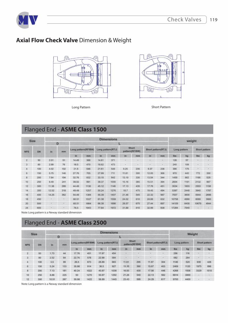
Check Valves120
Forged Steel Check Valve
1
2
3
1 Leak proof body-bonnet Joint Caving to eliminating the unwinding of the SSspiral metal.
2 Body guided disc to assure perfect alignment of disc and seat even at large fl ow velocities.
3 Swing Disc is Optional, While T-Pattern Piston Valve is available upon request.

Check Valves 121
Piston Check Valve G.A. Drawing of Piston Valve
Material List
Bolted Cover Welded Cover
Y Pattern Welded Cover Integral Flanged Ends

Check Valves122
Dimensions of Piston Valve
Class 800 Piston Type Bolted Cover or Welded Cover Regular and Full Port - ENISO 15761. Bolted Cover or Welded Cover - Threaded and Socket Weld Ends
Class 800 Y Pattern Welded Cover Full Port - ENISO 15761 Welded Cover - Threaded and Socket Weld Ends
Class 1500 Piston Type Bolted Cover or Welded Cover Regular and FullPort - ENISO 15761. Bolted Cover or Welded Cover - Threaded and Socket Weld Ends
Class 1500 Piston Type RTJ Cover Full Port - ENISO 15761. RTJ Cover - Threaded and SocketWeld Ends
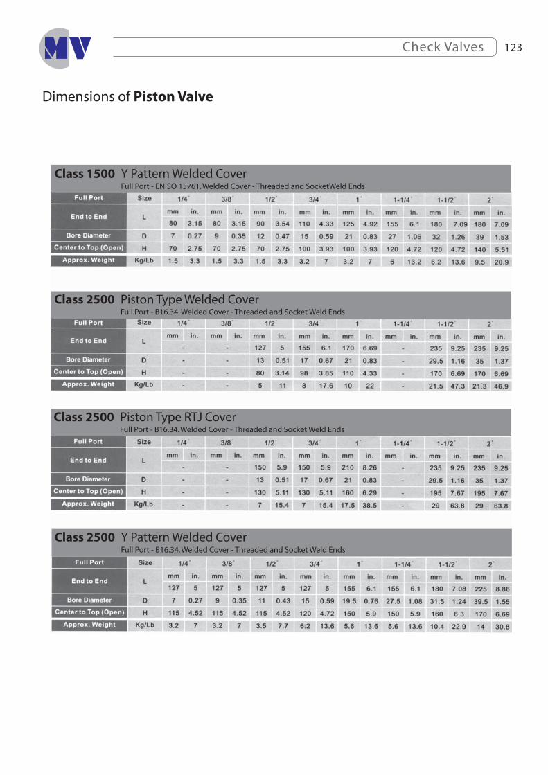
Check Valves 123
Dimensions of Piston Valve
Class 2500 Piston Type RTJ Cover Full Port - B16.34. Welded Cover - Threaded and Socket Weld Ends
Class 2500 Piston Type Welded Cover Full Port - B16.34. Welded Cover - Threaded and Socket Weld Ends
Class 1500 Y Pattern Welded Cover Full Port - ENISO 15761. Welded Cover - Threaded and SocketWeld Ends
Class 2500 Y Pattern Welded Cover Full Port - B16.34. Welded Cover - Threaded and Socket Weld Ends

Check Valves124
Dimensions of Piston Valve
Class 1500 RTJ Cover & Integral Flanged Ends Full Port - EN ISO 15761. RTJ Cover - Integral Flanged Ends according to ASME B 16.5
End to End dimensions according to ASME B 16.10
End to End dimensions according to ASME B 16.10
Class 150-300-600 Bolted Cover & Integral Flanged EndsRegular and Full Port - EN ISO 15761. Bolted Cover - Integral Flanged Ends according to ASME B 16.5

Check Valves 125
Swing Check Valve G.A. Drawing & Dimensions of Swing Check Valve
Material List
Class 800 Swing Type Bolted Cover Regular and Full Port - EN ISO 15761. Bolted Cover - Threaded and Socket Weld Ends
Bolted Cover

Check Valves126
Pressure Temperature Chart
Nylon Seats Tefl on Seats
PEEK Seats Delrin Seats
Carbon-f illed Seats Glass-f illed PTFE Seats
Check Valves 127
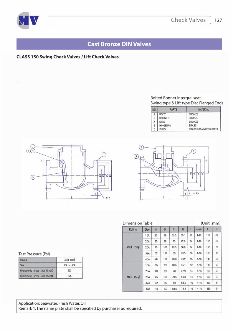
Application: Seawater, Fresh Water, OilRemark 1. The name plate shall be specifi ed by purchaser as required.
Cast Bronze DIN Valves
Bolted Bonnet Intergral seatSwing type & Lift type Disc Flanged Ends
(Unit : mm)Dimension Table
Test Pressure (Psi)
CLASS 150 Swing Check Valves / Lift Check Valves
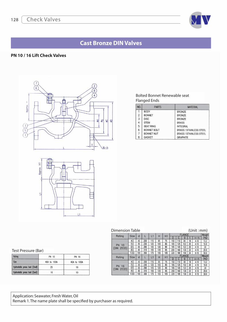
Check Valves128
Bolted Bonnet Renewable seatFlanged Ends
(Unit : mm)Dimension Table
Test Pressure (Bar)
FIG D3498 BZ
FIG D3497 BZ
Cast Bronze DIN Valves
PN 10 / 16 Lift Check Valves
Application: Seawater, Fresh Water, OilRemark 1. The name plate shall be specifi ed by purchaser as required.

Check Valves 129
Bolted Bonnet Renewable seatFlanged Ends
(Unit : mm)Dimension Table
Test Pressure (Bar)
Cast Iron DIN Valves
PN 10 / 16 Lift Check Valves
Application: Water, Oil, AirRemark 1. The name plate shall be specifi ed by purchaser as required.
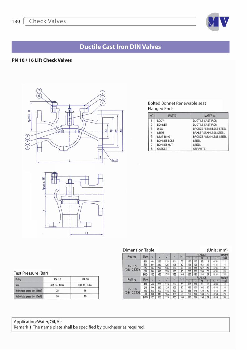
Check Valves130
Ductile Cast Iron DIN Valves
Bolted Bonnet Renewable seatFlanged Ends
(Unit : mm)Dimension Table
PN 10 / 16 Lift Check Valves
Test Pressure (Bar)
Application: Water, Oil, AirRemark 1. The name plate shall be specifi ed by purchaser as required.

Check Valves 131
Cast Bronze DIN Valves
Bolted Bonnet Renewable seatFlanged Ends
(Unit : mm)Dimension Table
Test Pressure (Bar)
PN 10 / 16 Feed Check Valves
Application: Seawater, Fresh Water, Oil, AirRemark 1. The name plate shall be specifi ed by purchaser as required.
Check Valves132
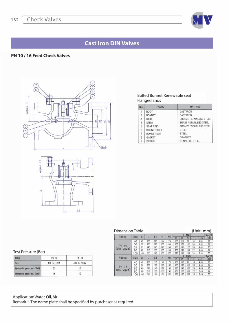
Cast Iron DIN Valves
Bolted Bonnet Renewable seatFlanged Ends
(Unit : mm)Dimension Table
Test Pressure (Bar)
FIG DS3101 CI
FIG DS3102 CI
PN 10 / 16 Feed Check Valves
Application: Water, Oil, AirRemark 1. The name plate shall be specifi ed by purchaser as required.

Check Valves 133
Ductile Cast Iron DIN Valves
Bolted Bonnet Renewable seatFlanged Ends
(Unit : mm)Dimension Table
Test Pressure (Bar)
PN 10 / 16 Feed Check Valves
Application: Water, Oil, AirRemark 1. The name plate shall be specifi ed by purchaser as required.
Check Valves134
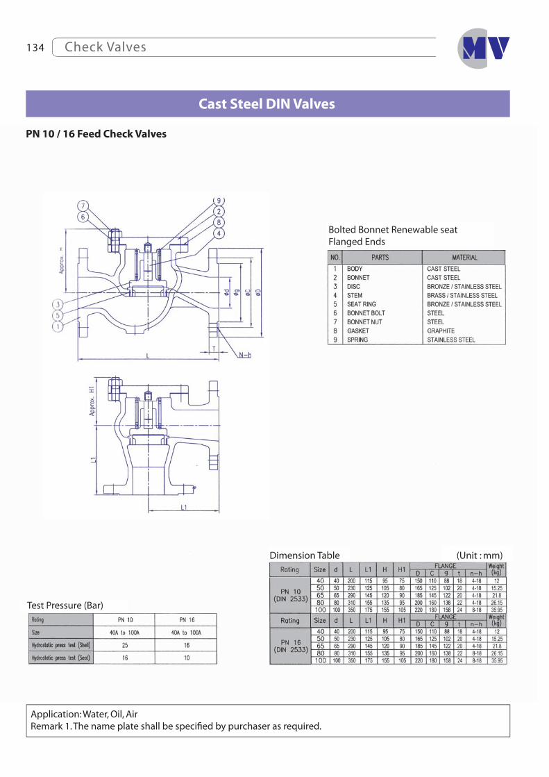
Cast Steel DIN Valves
Bolted Bonnet Renewable seatFlanged Ends
(Unit : mm)Dimension Table
Test Pressure (Bar)
PN 10 / 16 Feed Check Valves
Application: Water, Oil, AirRemark 1. The name plate shall be specifi ed by purchaser as required.

Check Valves 135
Cast Iron Marine Valves
Bolted Bonnet Renewable seatFlanged Ends
(Unit : mm)Dimension Table
Test Pressure (MPa)
Remark: 1. The fl anges shall conform to nominal pressure 5K and 10K of JIS B 2210.
Fluid Condition & Max. Working pressure (MPa)
JIS 5K Swing Check Valves JIS F7372
JIS 10K Swing Check Valves JIS F7373

Check Valves136
Cast Iron Marine Valves
Bolted Bonnet Renewable seatFlanged Ends
(Unit : mm)Dimension Table
Bolted Bonnet Renewable seatFlanged Ends
(Unit : mm)Dimension TableFluid Condition & Max. Working pressure (MPa)
Test Pressure (MPa)
Remark: 1. The fl anges shall conform to nominal pressure 5K of JIS B 2210.
JIS 5K Lift Check Globe Valves JIS F7358
JIS 5K Lift Check Angle Valves JIS F7359

Check Valves 137
Cast Iron Marine Valves
Bolted Bonnet Renewable seatFlanged Ends
(Unit : mm)Dimension Table
Test Pressure (MPa)
Application: Water, Oil, AirRemark: 1. The fl anges shall conform to nominal pressure 10K of JIS B2210.
JIS 10K Lift Check Globe Valves Ref. to JIS F7358
JIS 10K Lift Check Angle Valves Ref. to JIS F7359

Check Valves138
Cast Bronze Marine Valves
Bolted Bonnet Renewable seatFlanged Ends
(Unit : mm)Dimension TableFluid Condition & Max. Working pressure (MPa)
Test Pressure (MPa)
Remark: 1. The fl anges shall conform to nominal pressure 10K of JIS B 2240.
JIS 10K Swing Check Valves Ref. to JIS F7371
JIS 10K Lift Check Globe Valves Ref. to JIS F7356

Check Valves 139
Cast Bronze Marine Valves
Bolted Bonnet Renewable seatFlanged Ends
(Unit : mm)Dimension Table
Test Pressure (MPa)
Fluid Condition & Max. Working pressure (MPa)
Remark: 1. The fl anges shall conform to nominal pressure 5K of JIS B 2240.
JIS 5K Swing Check Valves JIS F7371
JIS 5K Lift Check Globe Valves JIS F7356
Check Valves140
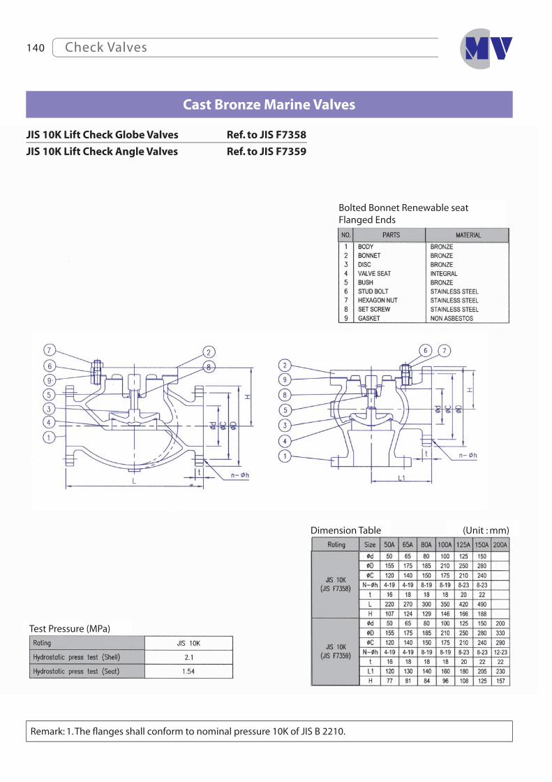
Cast Bronze Marine Valves
Bolted Bonnet Renewable seatFlanged Ends
(Unit : mm)Dimension Table
Test Pressure (MPa)
Remark: 1. The fl anges shall conform to nominal pressure 10K of JIS B 2210.
JIS 10K Lift Check Globe Valves Ref. to JIS F7358
JIS 10K Lift Check Angle Valves Ref. to JIS F7359


![Algorithms for Data Compression [Unlocked] – chap 9 [CLRS] – chap 16.3](https://img.pdfslide.us/doc/110x75/56649cfa5503460f949cc100/algorithms-for-data-compression-unlocked-chap-9-clrs-chap-163.jpg)