Embed Size (px)
Citation preview
Appl Phys A (2011) 102: 885–889DOI 10.1007/s00339-011-6318-z
Chaotic memristor
T. Driscoll · Y.V. Pershin · D.N. Basov · M. Di Ventra
Received: 18 October 2010 / Accepted: 22 December 2010 / Published online: 5 February 2011© The Author(s) 2011. This article is published with open access at Springerlink.com
Abstract We suggest and experimentally demonstrate achaotic memory resistor (memristor). The core of our ap-proach is to use a resistive system whose equations of mo-tion for its internal state variables are similar to those de-scribing a particle in a multi-well potential. Using a mem-ristor emulator, the chaotic memristor is realized and itschaotic properties are measured. A Poincaré plot showingchaos is presented for a simple nonautonomous circuit in-volving only a voltage source directly connected in seriesto a memristor and a standard resistor. We also explore the-oretically some details of this system, plotting the attractorand calculating Lyapunov exponents. The multi-well poten-tial used resembles that of many nanoscale memristive de-vices, suggesting the possibility of chaotic dynamics in otherexisting memristive systems.
1 Introduction
The class of memory circuit elements consisting of mem-ristors, memcapacitors and meminductors [1, 2] is a rela-tively new paradigm based on the understanding that many
T. Driscoll · D.N. Basov · M. Di Ventra (�)Department of Physics, University of California,9500 Gilman Drive, San Diego, La Jolla, CA 92093, USAe-mail: [email protected]
Present address:T. DriscollCenter for Metamaterials and Integrated Photonics,Department of Computer and Electrical Engineering,Duke University, Durham, NC 27708, USA
Y.V. PershinDepartment of Physics and Astronomy and USC Nanocenter,University of South Carolina, Columbia, SC 29208, USA
physical realizations of basic circuit elements (resistors, ca-pacitors and indicators) may involve an intrinsic memorymechanism, at least on certain time scales. Currently, a lotof attention is devoted to such elements and their potentialapplications—with a primary focus on memristive elements[3–5]. Physical manifestations of memristors range fromthermistors [6] to complex oxide [7–11] and spintronic [12–14] materials. A number of possible intriguing applicationsof memristors have already been discussed including digi-tal memory [15–17], neuromorphic systems [18–20], adap-tive filters [21, 22], tunable and reconfigurable metamateri-als [11], and others [23–25].
By definition [1, 4], an nth-order voltage-controlledmemristive system is described by the relations
I (t) = R−1M (x,VM, t)VM(t) (1)
x = f (x,VM, t) (2)
where VM(t) and I (t) denote the voltage across and currentthrough the device, RM is a scalar called the memristance,x is a vector representing n internal state variables, and f isan n-component vector function. Following present conven-tion, we will call a device described by (1)–(2) a memristor,even though the latter was originally defined when RM de-pends on charge or flux (time integral of voltage) only [3].
In this paper, we consider a specific type of second-ordermemristor described by (2) of the form
d
dt
[x
x
]=
[x
− 1m
∂U∂x
− γ x + F(VM)m
], (3)
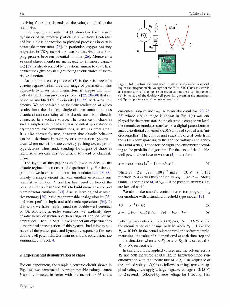
where x and x are internal state variables, m is an effec-tive mass associated with the internal state of the device,U(x) is a multi-well potential such that U(±∞) = ∞ (seeschematic in Fig. 1), γ is a damping coefficient and F is
886 T. Driscoll et al.
a driving force that depends on the voltage applied to thememristor.
It is important to note that (3) describes the classicaldynamics of an effective particle in a multi-well potentialand has a close connection to physical processes in certainnanoscale memristors [26]. In particular, oxygen vacancymigration in TiO2 memristors can be described as a hop-ping process between potential minima [26]. Moreover, astrained elastic membrane memcapacitor (memory capaci-tor) [27] is also described by equations similar to (3). Theseconnections give physical grounding to our choice of mem-ristive function.
An important consequence of (3) is the existence of achaotic regime within a certain range of parameters. Thisapproach to chaos with memristors is unique and radi-cally different from previous proposals [22, 28–30] that arebased on modified Chua’s circuits [31, 32] with active el-ements. We emphasize also that our realization of chaosresults from the simplest single-element nonautonomouschaotic circuit consisting of the chaotic memristor directlyconnected to a voltage source. The presence of chaos insuch a simple system certainly has potential applications incryptography and communications, as well as other areas.It is also conversely true, however, that chaotic behaviorcan be a detriment in memory or computation systems—areas where memristors are currently pushing toward proto-type devices. Thus, understanding the origins of chaos inmemristive systems may be critical to avoid or eliminatechaos.
The layout of this paper is as follows: In Sect. 2, thechaotic regime is demonstrated experimentally. For the ex-periment, we have built a memristor emulator [20, 23, 33],namely a simple circuit that can emulate essentially anymemristive function f , and has been used by two of thepresent authors (YVP and MD) to build memcapacitor andmeminductor emulators [33], discuss learning and associa-tive memory [20], build programmable analog circuits [23],and even perform logic and arithmetic operations [34]. Inthis work we have implemented the double-well potentialof (3). Applying ac-pulse sequences, we explicitly showchaotic behavior within a certain range of applied voltageamplitudes. Then, in Sect. 3, we connect our experiment toa theoretical investigation of this system, including explo-ration of the phase space and Lyapunov exponents for suchdouble-well potentials. Our main results and conclusions aresummarized in Sect. 4.
2 Experimental demonstration of chaos
For our experiment, the simple electronic circuit shown inFig. 1(a) was constructed. A programmable voltage sourceV (t) is connected in series with the memristor M and a
Fig. 1 (a) Electronic circuit used in chaos measurements consist-ing of the programmable voltage source V (t), 510 Ohms resistor R0and memristor M . The memristor specifications are given in the text.(b) Schematic of the double-well potential governing the memristor.(c) Optical photograph of memristor emulator
current-sensing resistor R0. A memristor emulator [20, 23,33] whose circuit image is shown in Fig. 1(c) was em-ployed for the memristor. At the electronic component level,the memristor emulator consists of a digital potentiometer,analog-to-digital converter (ADC) unit and control unit (mi-crocontroller). The control unit reads the digital code fromthe ADC (corresponding to the applied voltage) and gener-ates (and writes) a code for the digital potentiometer accord-ing to the predefined algorithm. For the case of the double-well potential we have re-written (3) in the form
x = −c1x − c2x(x2 − 1
) + c3VM(t), (4)
where c1 = 2 s−1, c2 = 100 s−2 and c3 = 30 V−1 s−2. Thefunction RM(x) was then chosen as RM = (4875 + 1560x)
Ohms. According to (4) at VM = 0 the potential minima ±x0
are located at ±1.We also make use of a control memristor, programming
our emulator with a standard threshold-type model [19]
I (t) = x−1VM(t), (5)
x = −βVM + 0.5β(|VM + VT | − |VM − VT |) (6)
with the parameters β = 62 k�/(V·s), VT = 0.625 V, andthe memristance can change only between R1 = 1 k� andR2 = 10 k�. In the actual microcontroller’s software imple-mentation, the value of x is monitored at each time step andin the situations when x < R1 or x > R2, it is set equal toR1 or R2, respectively.
In this circuit, the applied voltage and the voltage acrossR0 are both measured at 800 Hz, in hardware-timed syn-chronization with the update rate of V (t). The sequence ofthe applied voltage V (t) is as follows: starting from zero ap-plied voltage, we apply a large negative voltage (−2.25 V)for 2 seconds, followed by zero voltage for 1 second. This
Chaotic memristor 887
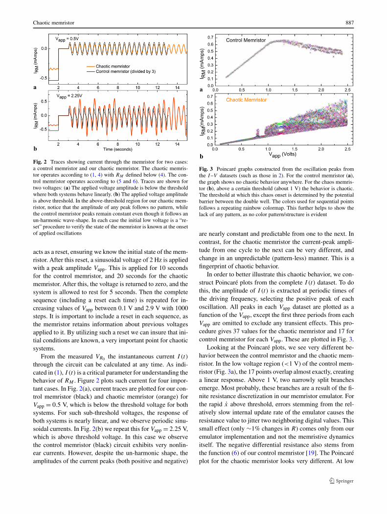
Fig. 2 Traces showing current through the memristor for two cases:a control memristor and our chaotic memristor. The chaotic memris-tor operates according to (1, 4) with RM defined below (4). The con-trol memristor operates according to (5 and 6). Traces are shown fortwo voltages: (a) The applied voltage amplitude is below the thresholdwhere both systems behave linearly. (b) The applied voltage amplitudeis above threshold. In the above-threshold region for our chaotic mem-ristor, notice that the amplitude of any peak follows no pattern, whilethe control memristor peaks remain constant even though it follows anun-harmonic wave-shape. In each case the initial low voltage is a “re-set” procedure to verify the state of the memristor is known at the onsetof applied oscillations
acts as a reset, ensuring we know the initial state of the mem-ristor. After this reset, a sinusoidal voltage of 2 Hz is appliedwith a peak amplitude Vapp. This is applied for 10 secondsfor the control memristor, and 20 seconds for the chaoticmemristor. After this, the voltage is returned to zero, and thesystem is allowed to rest for 5 seconds. Then the completesequence (including a reset each time) is repeated for in-creasing values of Vapp between 0.1 V and 2.9 V with 1000steps. It is important to include a reset in each sequence, asthe memristor retains information about previous voltagesapplied to it. By utilizing such a reset we can insure that ini-tial conditions are known, a very important point for chaoticsystems.
From the measured VR0 the instantaneous current I (t)
through the circuit can be calculated at any time. As indi-cated in (1), I (t) is a critical parameter for understanding thebehavior of RM . Figure 2 plots such current for four impor-tant cases. In Fig. 2(a), current traces are plotted for our con-trol memristor (black) and chaotic memristor (orange) forVapp = 0.5 V, which is below the threshold voltage for bothsystems. For such sub-threshold voltages, the response ofboth systems is nearly linear, and we observe periodic sinu-soidal currents. In Fig. 2(b) we repeat this for Vapp = 2.25 V,which is above threshold voltage. In this case we observethe control memristor (black) circuit exhibits very nonlin-ear currents. However, despite the un-harmonic shape, theamplitudes of the current peaks (both positive and negative)
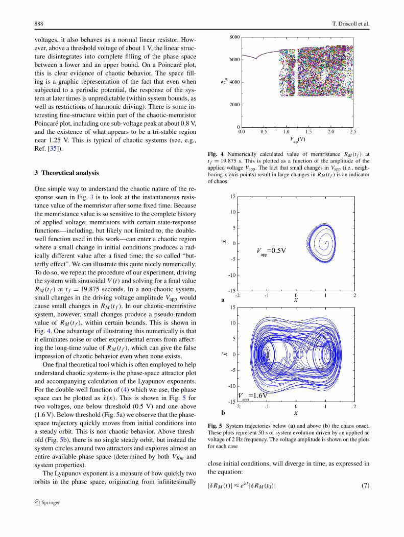
Fig. 3 Poincaré graphs constructed from the oscillation peaks fromthe I–V datasets (such as those in 2). For the control memristor (a),the graph shows no chaotic behavior anywhere. For the chaos memris-tor (b), above a certain threshold (about 1 V) the behavior is chaotic.The threshold at which this chaos onset is determined by the potentialbarrier between the double well. The colors used for sequential pointsfollows a repeating rainbow colormap. This further helps to show thelack of any pattern, as no color pattern/structure is evident
are nearly constant and predictable from one to the next. Incontrast, for the chaotic memristor the current-peak ampli-tude from one cycle to the next can be very different, andchange in an unpredictable (pattern-less) manner. This is afingerprint of chaotic behavior.
In order to better illustrate this chaotic behavior, we con-struct Poincaré plots from the complete I (t) dataset. To dothis, the amplitude of I (t) is extracted at periodic times ofthe driving frequency, selecting the positive peak of eachoscillation. All peaks in each Vapp dataset are plotted as afunction of the Vapp, except the first three periods from eachVapp are omitted to exclude any transient effects. This pro-cedure gives 37 values for the chaotic memristor and 17 forcontrol memristor for each Vapp. These are plotted in Fig. 3.
Looking at the Poincaré plots, we see very different be-havior between the control memristor and the chaotic mem-ristor. In the low voltage region (<1 V) of the control mem-ristor (Fig. 3a), the 17 points overlap almost exactly, creatinga linear response. Above 1 V, two narrowly split branchesemerge. Most probably, these branches are a result of the fi-nite resistance discretization in our memristor emulator. Forthe rapid x above threshold, errors stemming from the rel-atively slow internal update rate of the emulator causes theresistance value to jitter two neighboring digital values. Thissmall effect (only ∼1% changes in R) comes only from ouremulator implementation and not the memristive dynamicsitself. The negative differential resistance also stems fromthe function (6) of our control memristor [19]. The Poincaréplot for the chaotic memristor looks very different. At low
888 T. Driscoll et al.
voltages, it also behaves as a normal linear resistor. How-ever, above a threshold voltage of about 1 V, the linear struc-ture disintegrates into complete filling of the phase spacebetween a lower and an upper bound. On a Poincaré plot,this is clear evidence of chaotic behavior. The space fill-ing is a graphic representation of the fact that even whensubjected to a periodic potential, the response of the sys-tem at later times is unpredictable (within system bounds, aswell as restrictions of harmonic driving). There is some in-teresting fine-structure within part of the chaotic-memristorPoincaré plot, including one sub-voltage peak at about 0.8 V,and the existence of what appears to be a tri-stable regionnear 1.25 V. This is typical of chaotic systems (see, e.g.,Ref. [35]).
3 Theoretical analysis
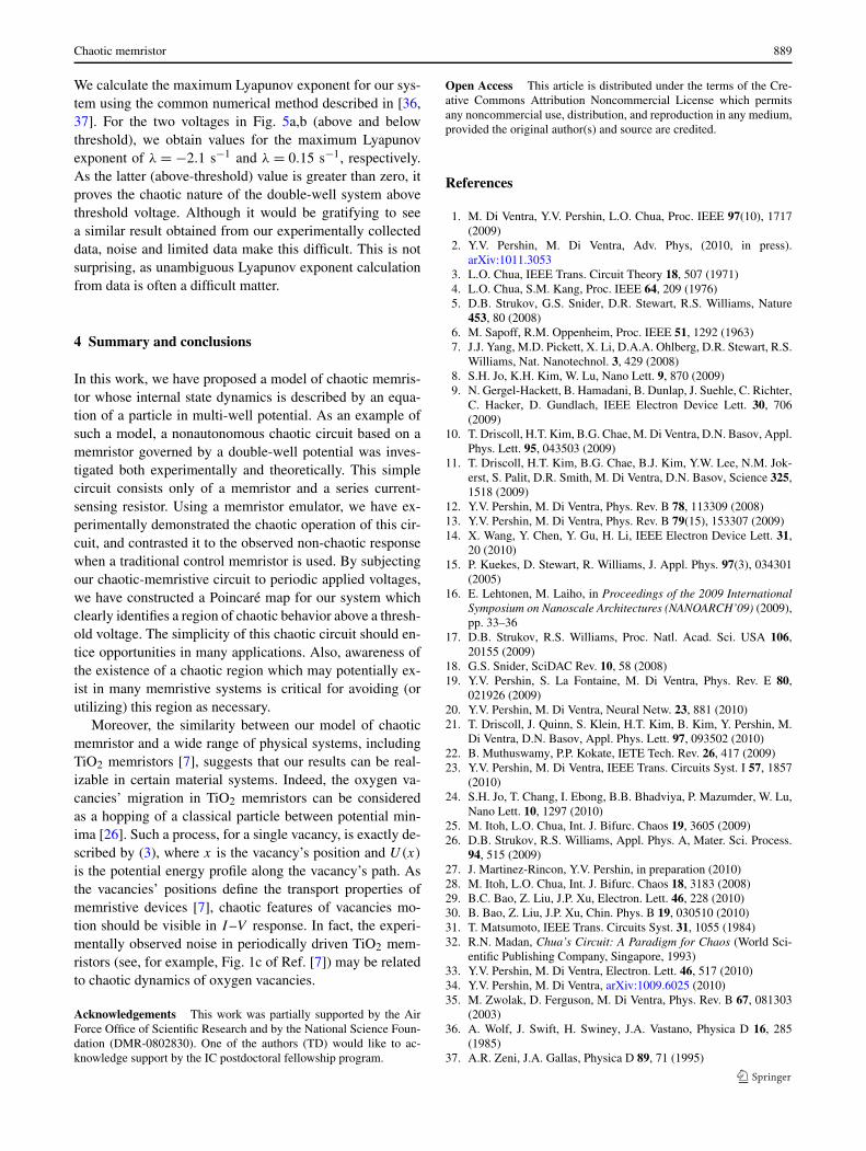
One simple way to understand the chaotic nature of the re-sponse seen in Fig. 3 is to look at the instantaneous resis-tance value of the memristor after some fixed time. Becausethe memristance value is so sensitive to the complete historyof applied voltage, memristors with certain state-responsefunctions—including, but likely not limited to, the double-well function used in this work—can enter a chaotic regionwhere a small change in initial conditions produces a rad-ically different value after a fixed time; the so called “but-terfly effect”. We can illustrate this quite nicely numerically.To do so, we repeat the procedure of our experiment, drivingthe system with sinusoidal V (t) and solving for a final valueRM(tf ) at tf = 19.875 seconds. In a non-chaotic system,small changes in the driving voltage amplitude Vapp wouldcause small changes in RM(tf ). In our chaotic-memristivesystem, however, small changes produce a pseudo-randomvalue of RM(tf ), within certain bounds. This is shown inFig. 4. One advantage of illustrating this numerically is thatit eliminates noise or other experimental errors from affect-ing the long-time value of RM(tf ), which can give the falseimpression of chaotic behavior even when none exists.
One final theoretical tool which is often employed to helpunderstand chaotic systems is the phase-space attractor plotand accompanying calculation of the Lyapunov exponents.For the double-well function of (4) which we use, the phasespace can be plotted as x(x). This is shown in Fig. 5 fortwo voltages, one below threshold (0.5 V) and one above(1.6 V). Below threshold (Fig. 5a) we observe that the phase-space trajectory quickly moves from initial conditions intoa steady orbit. This is non-chaotic behavior. Above thresh-old (Fig. 5b), there is no single steady orbit, but instead thesystem circles around two attractors and explores almost anentire available phase space (determined by both VRm andsystem properties).
The Lyapunov exponent is a measure of how quickly twoorbits in the phase space, originating from infinitesimally
Fig. 4 Numerically calculated value of memristance RM(tf ) attf = 19.875 s. This is plotted as a function of the amplitude of theapplied voltage Vapp. The fact that small changes in Vapp (i.e., neigh-boring x-axis points) result in large changes in RM(tf ) is an indicatorof chaos
Fig. 5 System trajectories below (a) and above (b) the chaos onset.These plots represent 50 s of system evolution driven by an applied acvoltage of 2 Hz frequency. The voltage amplitude is shown on the plotsfor each case
close initial conditions, will diverge in time, as expressed inthe equation:
|δRM(t)| ≈ eλt |δRM(t0)| (7)
Chaotic memristor 889
We calculate the maximum Lyapunov exponent for our sys-tem using the common numerical method described in [36,37]. For the two voltages in Fig. 5a,b (above and belowthreshold), we obtain values for the maximum Lyapunovexponent of λ = −2.1 s−1 and λ = 0.15 s−1, respectively.As the latter (above-threshold) value is greater than zero, itproves the chaotic nature of the double-well system abovethreshold voltage. Although it would be gratifying to seea similar result obtained from our experimentally collecteddata, noise and limited data make this difficult. This is notsurprising, as unambiguous Lyapunov exponent calculationfrom data is often a difficult matter.
4 Summary and conclusions
In this work, we have proposed a model of chaotic memris-tor whose internal state dynamics is described by an equa-tion of a particle in multi-well potential. As an example ofsuch a model, a nonautonomous chaotic circuit based on amemristor governed by a double-well potential was inves-tigated both experimentally and theoretically. This simplecircuit consists only of a memristor and a series current-sensing resistor. Using a memristor emulator, we have ex-perimentally demonstrated the chaotic operation of this cir-cuit, and contrasted it to the observed non-chaotic responsewhen a traditional control memristor is used. By subjectingour chaotic-memristive circuit to periodic applied voltages,we have constructed a Poincaré map for our system whichclearly identifies a region of chaotic behavior above a thresh-old voltage. The simplicity of this chaotic circuit should en-tice opportunities in many applications. Also, awareness ofthe existence of a chaotic region which may potentially ex-ist in many memristive systems is critical for avoiding (orutilizing) this region as necessary.
Moreover, the similarity between our model of chaoticmemristor and a wide range of physical systems, includingTiO2 memristors [7], suggests that our results can be real-izable in certain material systems. Indeed, the oxygen va-cancies’ migration in TiO2 memristors can be consideredas a hopping of a classical particle between potential min-ima [26]. Such a process, for a single vacancy, is exactly de-scribed by (3), where x is the vacancy’s position and U(x)
is the potential energy profile along the vacancy’s path. Asthe vacancies’ positions define the transport properties ofmemristive devices [7], chaotic features of vacancies mo-tion should be visible in I–V response. In fact, the experi-mentally observed noise in periodically driven TiO2 mem-ristors (see, for example, Fig. 1c of Ref. [7]) may be relatedto chaotic dynamics of oxygen vacancies.
Acknowledgements This work was partially supported by the AirForce Office of Scientific Research and by the National Science Foun-dation (DMR-0802830). One of the authors (TD) would like to ac-knowledge support by the IC postdoctoral fellowship program.
Open Access This article is distributed under the terms of the Cre-ative Commons Attribution Noncommercial License which permitsany noncommercial use, distribution, and reproduction in any medium,provided the original author(s) and source are credited.
References
1. M. Di Ventra, Y.V. Pershin, L.O. Chua, Proc. IEEE 97(10), 1717(2009)
2. Y.V. Pershin, M. Di Ventra, Adv. Phys, (2010, in press).arXiv:1011.3053
3. L.O. Chua, IEEE Trans. Circuit Theory 18, 507 (1971)4. L.O. Chua, S.M. Kang, Proc. IEEE 64, 209 (1976)5. D.B. Strukov, G.S. Snider, D.R. Stewart, R.S. Williams, Nature
453, 80 (2008)6. M. Sapoff, R.M. Oppenheim, Proc. IEEE 51, 1292 (1963)7. J.J. Yang, M.D. Pickett, X. Li, D.A.A. Ohlberg, D.R. Stewart, R.S.
Williams, Nat. Nanotechnol. 3, 429 (2008)8. S.H. Jo, K.H. Kim, W. Lu, Nano Lett. 9, 870 (2009)9. N. Gergel-Hackett, B. Hamadani, B. Dunlap, J. Suehle, C. Richter,
C. Hacker, D. Gundlach, IEEE Electron Device Lett. 30, 706(2009)
10. T. Driscoll, H.T. Kim, B.G. Chae, M. Di Ventra, D.N. Basov, Appl.Phys. Lett. 95, 043503 (2009)
11. T. Driscoll, H.T. Kim, B.G. Chae, B.J. Kim, Y.W. Lee, N.M. Jok-erst, S. Palit, D.R. Smith, M. Di Ventra, D.N. Basov, Science 325,1518 (2009)
12. Y.V. Pershin, M. Di Ventra, Phys. Rev. B 78, 113309 (2008)13. Y.V. Pershin, M. Di Ventra, Phys. Rev. B 79(15), 153307 (2009)14. X. Wang, Y. Chen, Y. Gu, H. Li, IEEE Electron Device Lett. 31,
20 (2010)15. P. Kuekes, D. Stewart, R. Williams, J. Appl. Phys. 97(3), 034301
(2005)16. E. Lehtonen, M. Laiho, in Proceedings of the 2009 International
Symposium on Nanoscale Architectures (NANOARCH’09) (2009),pp. 33–36
17. D.B. Strukov, R.S. Williams, Proc. Natl. Acad. Sci. USA 106,20155 (2009)
18. G.S. Snider, SciDAC Rev. 10, 58 (2008)19. Y.V. Pershin, S. La Fontaine, M. Di Ventra, Phys. Rev. E 80,
021926 (2009)20. Y.V. Pershin, M. Di Ventra, Neural Netw. 23, 881 (2010)21. T. Driscoll, J. Quinn, S. Klein, H.T. Kim, B. Kim, Y. Pershin, M.
Di Ventra, D.N. Basov, Appl. Phys. Lett. 97, 093502 (2010)22. B. Muthuswamy, P.P. Kokate, IETE Tech. Rev. 26, 417 (2009)23. Y.V. Pershin, M. Di Ventra, IEEE Trans. Circuits Syst. I 57, 1857
(2010)24. S.H. Jo, T. Chang, I. Ebong, B.B. Bhadviya, P. Mazumder, W. Lu,
Nano Lett. 10, 1297 (2010)25. M. Itoh, L.O. Chua, Int. J. Bifurc. Chaos 19, 3605 (2009)26. D.B. Strukov, R.S. Williams, Appl. Phys. A, Mater. Sci. Process.
94, 515 (2009)27. J. Martinez-Rincon, Y.V. Pershin, in preparation (2010)28. M. Itoh, L.O. Chua, Int. J. Bifurc. Chaos 18, 3183 (2008)29. B.C. Bao, Z. Liu, J.P. Xu, Electron. Lett. 46, 228 (2010)30. B. Bao, Z. Liu, J.P. Xu, Chin. Phys. B 19, 030510 (2010)31. T. Matsumoto, IEEE Trans. Circuits Syst. 31, 1055 (1984)32. R.N. Madan, Chua’s Circuit: A Paradigm for Chaos (World Sci-
entific Publishing Company, Singapore, 1993)33. Y.V. Pershin, M. Di Ventra, Electron. Lett. 46, 517 (2010)34. Y.V. Pershin, M. Di Ventra, arXiv:1009.6025 (2010)35. M. Zwolak, D. Ferguson, M. Di Ventra, Phys. Rev. B 67, 081303
(2003)36. A. Wolf, J. Swift, H. Swiney, J.A. Vastano, Physica D 16, 285
(1985)37. A.R. Zeni, J.A. Gallas, Physica D 89, 71 (1995)
![Modeling of the Memristor in SPICE Introduction In 1971, professor Chua predicted the existence of the fourth circuit element – memristor [3]. The memristor](https://img.pdfslide.us/doc/110x75/56649e3b5503460f94b2d7a3/modeling-of-the-memristor-in-spice-introduction-in-1971-professor-chua-predicted.jpg)