Embed Size (px)
Citation preview

Chaotic Advection in MultiChaotic Advection in Multi--component Meltscomponent Meltsfor thefor thefor thefor the
Manufacture of Composite MaterialsManufacture of Composite Materials
Presented to a Session on Complex FluidsPresented to a Session on Complex FluidsMeeting of the Southeast Section of the American Physical Society
October 20, 2011by
D. A. (Dave) ZumbrunnenWarren H. Owen-Duke Energy Professor
y
Department of Mechanical EngineeringClemson University
[email protected] 656 5625

DedicationDedication
Dr. Hassan Aref: The father of chaotic advection and the person who most profoundly influenced my research. Smart blending was truly enabled by chaotic advection.
D. A. Zumbrunnen
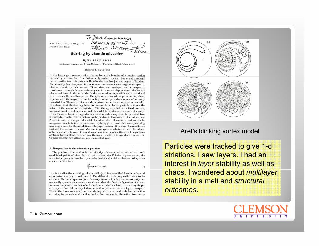
Aref’s blinking vortex model
Particles were tracked to give 1-d striations. I saw layers. I had an interest in layer stability as well as h I d d b t ltilchaos. I wondered about multilayer
stability in a melt and structural outcomes.
D. A. Zumbrunnen

Contents of this seminar• Chaotic advection and its application to controllable in situstructure formation (smart blending)
• Computational modeling and physics of in situ structureformation
• Physical properties of some novel plastic materials producedPhysical properties of some novel plastic materials produced
Toughness
Electrical conductivity Controlled release
Solvent resistancey
Permeation reduction (barrier)
• Other applications (manufacturing and rheology)
Patterning (wood grains)
Not covered• Suggested areas for further study
• Discussion
Not covered
D. A. Zumbrunnen

Acknowledgements
Financial support: NSF, DARPA, US Dept. of the Army, US Dept. of Commerce 3M Company Appleton Kuraray America ILC Dover
Acknowledgements
of Commerce, 3M Company, Appleton, Kuraray America, ILC Dover, Dow Chemical Company, Pliant Corporation Research assistants: V. Chougule, C. Chhibber, R. Danescu , A. Dhoble S Inamdar B Gomillion A Joshi * Y Liu C Mahesha KDhoble, S. Inamdar, B. Gomillion, A. Joshi,* Y. Liu, C. Mahesha, K. Miles, B. Nagarajan, Y. Parulekar, P. Keener, P. Verma, W. Wright, D. Zhang
*Lattice Boltzmann modeling that is presented in this talk was performed by Abhijit Joshi in conjunction with his doctoral studies.
Post-doctoral research associates: R. Danescu, O. Kwon, B.Post doctoral research associates: R. Danescu, O. Kwon, B. Kulshreshtha, X. Jin
D. A. Zumbrunnen

Co-extrusion: To putCo-extrusion: To put together only in one manner.
Mixing: To put together indiscriminately or confusedlyy y(Ref: American College Dictionary).
Observation: Plastics that combine different polymertypes or polymers and solids are either co-extruded ormixed. Structural outcomes are limited and are notnecessarily associated with optimal results.
D. A. Zumbrunnen
Progressive structure (morphology) development
Processing conditions where fine-scale shapes amongProcessing conditions where fine-scale shapes amongmelt components or arrangements among solidadditives are formed progressively in situ. A variety of
l bl d h l i bt i d ipolymer blend morphologies are obtained viasequential morphology transitions.
Chaotic advection is enabling to progressive structure development and thereby smart blending.
D. A. Zumbrunnen

Chaotic advection: What is it?
Chaotic motion of passive particlesChaotic motion of passive particles in a fluid.
Wh t i it l t t bl di ?What is its relevance to smart blending?
The collective chaotic motions of melt domains cause successivemelt domains cause successive shear deformations and reorientations. A layered morphology first arises that may lead to other ymorphologies. Morphology development can be controlled.
D. A. Zumbrunnen
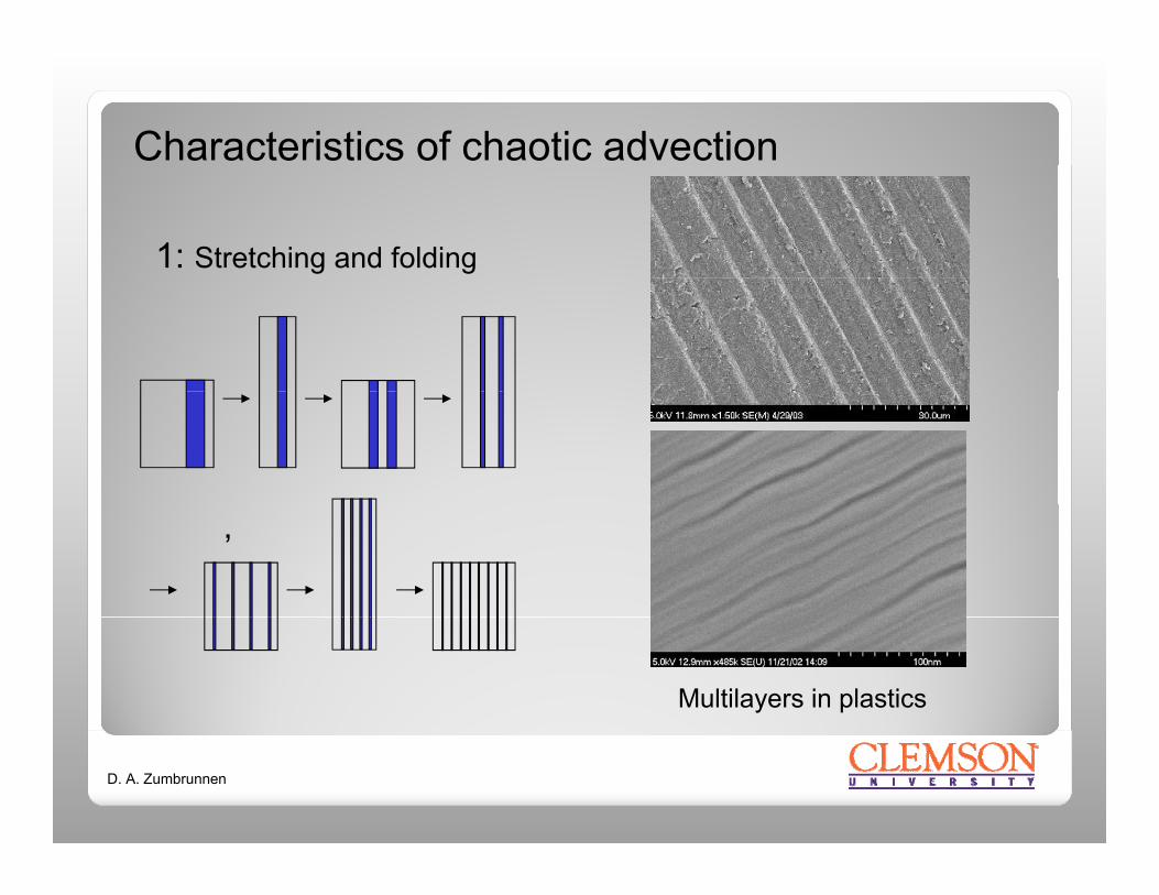
Characteristics of chaotic advection
1: Stretching and folding
‚
Multilayers in plastics
D. A. Zumbrunnen

Characteristics of chaotic advection
2: Sensitivity to initial conditions
Initial Particle Cluster
2: Sensitivity to initial conditions
Electrically conducting plastics
D. A. Zumbrunnen
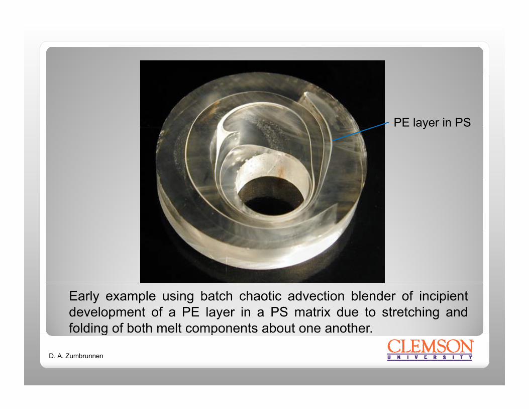
PE layer in PSy
Early example using batch chaotic advection blender of incipientdevelopment of a PE layer in a PS matrix due to stretching andfolding of both melt components about one another.g p
D. A. Zumbrunnen

Laboratory smart blender test bed
Various dies can be installed to produce structured materials of essentially any shape.
D. A. Zumbrunnen
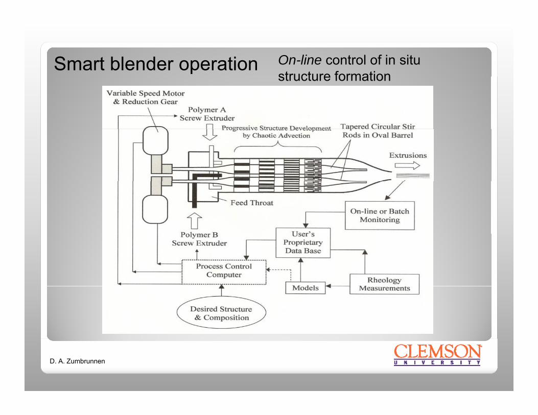
Smart blender operation On-line control of in situstructure formationstructure formation
D. A. Zumbrunnen

Progressive structure development in PP/LDPE 70/30% blends
Droplets finally result such as obtaining by conventional processing.
D. A. Zumbrunnen
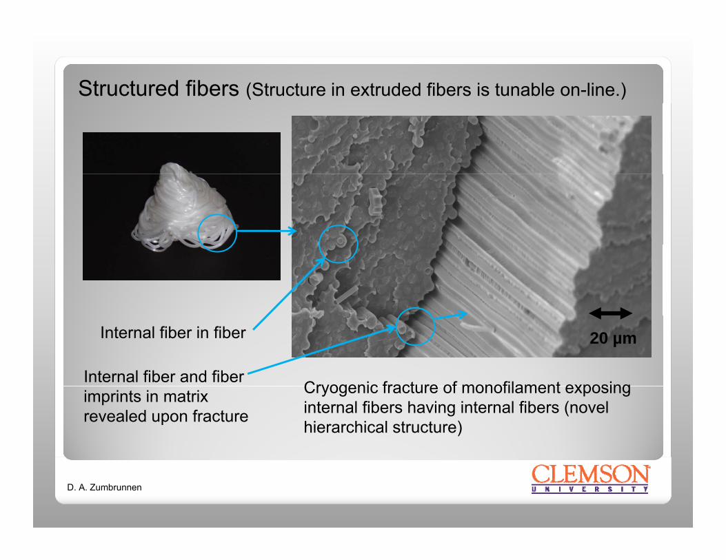
Structured fibers (Structure in extruded fibers is tunable on-line.)
Cryogenic fracture of monofilament exposing
Internal fiber in fiber
Internal fiber and fiber
20 µm
Cryogenic fracture of monofilament exposing internal fibers having internal fibers (novel hierarchical structure)
imprints in matrix revealed upon fracture
D. A. Zumbrunnen
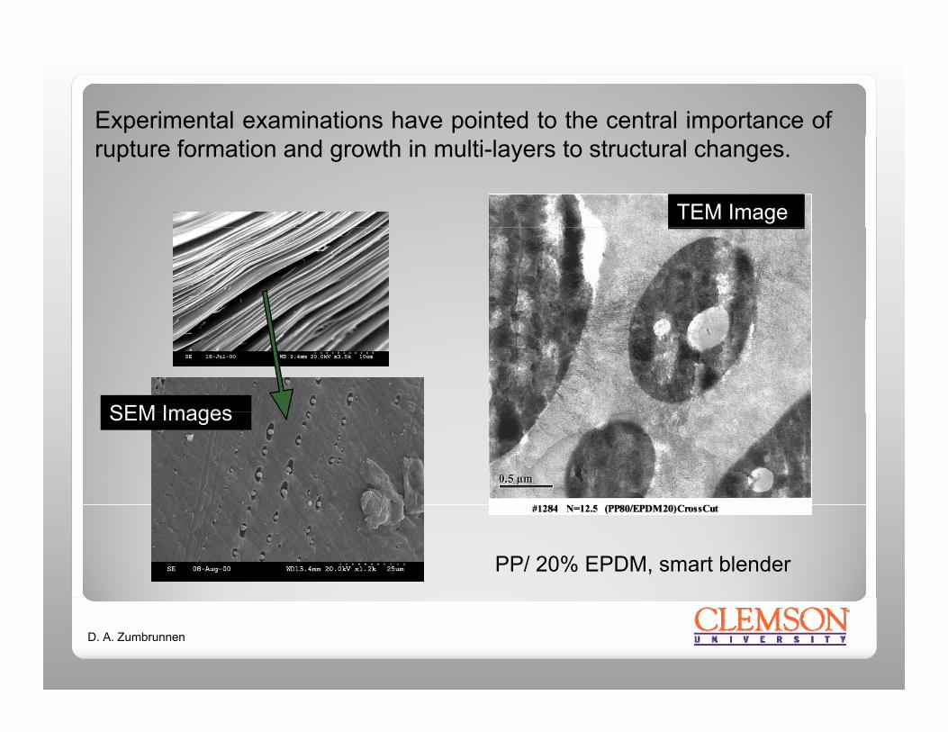
Experimental examinations have pointed to the central importance ofrupture formation and growth in multi-layers to structural changes.
TEM Image
SEM ImagesSEM Images
PP/ 20% EPDM, smart blender
D. A. Zumbrunnen

Shape of the hole interface resembles the t bl t idstable catenoid
shape, but does not have fixed edges.
Soap film between two rings forms a stable catenoid surface under certain Hole in a fluid layer
g
• A single hole formed in a fluid layer can NEVER BE IN STABLE EQUILIBRIUM.
conditions
• The hole either grows or shrinks.
• How and why do holes form in thin layers ?
D. A. Zumbrunnen

A3h
AP
P = conjoining pressure
h = layer thickness
A = Hamaker constantA = Hamaker constant
Conjoining pressure causes instability (Kheshgi & Scriven,1991)
D. A. Zumbrunnen
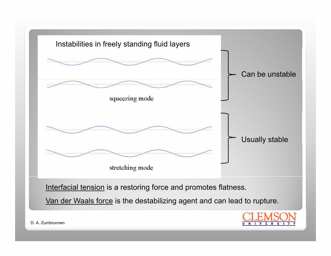
Instabilities in freely standing fluid layersy g y
Can be unstable
Usually stable
Interfacial tension is a restoring force and promotes flatness.
Van der Waals force is the destabilizing agent and can lead to rupture.
D. A. Zumbrunnen

Local modeling by Lattice Boltzmann Method (LBM)
F1
*
F2
A single hole can grow if the hole diameter d is greater than twice the layerthickness h1. Interfacial force F2 dominates F1 under this condition.
D. A. Zumbrunnen

Local modeling by Lattice Boltzmann Method (LBM)
3D analog to more familiarmore familiar dewetting of a surface by a
Growth in ruptures
yliquid layer
Growth in ruptures of multi-layers occurs in tandem with melt redistribution and
h l hmorphology changes.
D. A. Zumbrunnen

Fiber formation at low minor component compositionsFiber formation at low minor component compositions(single component continuity)
M i liMovie clip
At low compositions, little layer interaction occurs and fibers emerge fromand fibers emerge from rupture growth and coalescence.
D. A. Zumbrunnen

Formation of interpenetrating blend morphologyFormation of interpenetrating blend morphology(dual component continuity)
Movie clip
At intermediate compositions, layer interaction occurs as ruptures grow to give sponge-like blend morphologies.
D. A. Zumbrunnen

Formation of interpenetratingFormation of interpenetratingblend morphology with initialrandom rupture locations
D. A. Zumbrunnen

Formation of sieve-like structures and small dropletsp
Random holes
OrganizedOrganized holes
Droplet diameter is related to the parentlayer thicknesses so very small diameterslayer thicknesses so very small diameterscan result.
D. A. Zumbrunnen

Impact toughness improvements in PP/EPDM 80/20 blends
(J)
1000
(b)N=10
p g p
(Increase
pact
Str
engt
h (
600
800(Increase for blend relative to PP alone)
ncre
ase
in Im
p0
200
400
N
4 6 8 10 12 14 16 18
% In 0
Interconnected multilayer morphology is shown subsequent to cryogenic fracture and solvent removal of EPDM. Coalesced layers via ruptures increase toughness.
D. A. Zumbrunnen

Impact toughness improvements in polypropyleneImpact toughness improvements in polypropylene
Multilayer, N=8 Droplet N=16Thin, interconnected
In addition to toughness increases, the impact failure of PP-EPDM
Multilayer, N 8 Droplet, N=16Thin, interconnected layers, N=10
g , pfilms was qualitatively changed by blend morphology. Crack propagation was suppressed.
D. A. Zumbrunnen
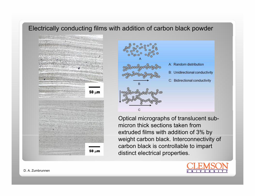
Electrically conducting films with addition of carbon black powder
Optical micrographs of translucent sub-micron thick sections taken from extruded films with addition of 3% by yweight carbon black. Interconnectivity of carbon black is controllable to impart distinct electrical properties.
D. A. Zumbrunnen

Electrically conducting films with addition of carbon black powder
107
CB wt%3cm
)
Novel reverse percolation effect
105
1063
2.5 2 1.5
ivity
(Ohm
-c
103
104
lum
e R
esis
t
0 4 8 12 16 20 24 28102
Vo
N
Resistivites pertain to the extrusion (or machine) direction for various overall carbon black compositions. Electrical properties can be selected or tuned via on-line process control.
D. A. Zumbrunnen
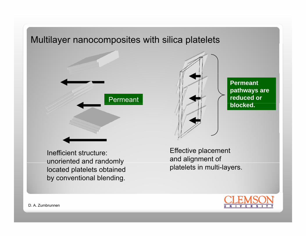
Multilayer nanocomposites with silica plateletsy p p
Permeant
Permeant pathways are reduced or bl k dblocked.
Inefficient structure: unoriented and randomly
Effective placement and alignment of unoriented and randomly
located platelets obtained by conventional blending.
platelets in multi-layers.
D. A. Zumbrunnen

Multilayer nanocomposites with silica plateletsy p p
(Masterbatch)Recursive horseshoe mappings (or baker’s transformations), platelets become oriented within the layers that contain them which also decrease in thickness to nano-scales.
(Masterbatch)
D. A. Zumbrunnen
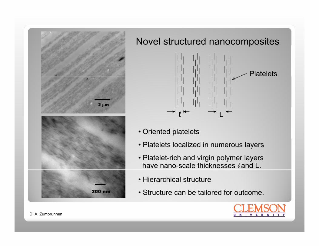
Novel structured nanocompositesp
Platelets
• Oriented platelets
ℓ L
• Platelets localized in numerous layers
• Platelet-rich and virgin polymer layershave nano-scale thicknesses l and L.
• Hierarchical structure
• Structure can be tailored for outcome.
D. A. Zumbrunnen

“Ultra-dispersion” of nano-platelets (TEM image)
Chaotic advection can be continued until layerbe continued until layer thicknesses are thinner than the nano-platelet dimensions. The result is an ultra-dispersion where the nano-platelets are shown obliquely.
D. A. Zumbrunnen

In situ structuring rheometer(Chaotic advection applied to rheology)
Blending cavity
Smart blender prior to installation
y
p
Applications: Rheological properties of polymer blends, nanocomposites, mixtures, biological fluids, percolating networks in melts……..
D. A. Zumbrunnen

Industrial smart blenders(Cast film or sheet, general purpose)
Smart blender prior to installationp
Research has resulted in industrial smart blenders that expand greatly the variety and properties of plastic products producible. Various dies can be attached.
D. A. Zumbrunnen

Additional information:Zumbrunnen, D. A., Miles, K. C., and Liu, Y. H, "Auto-Processing of Very Fine-Scale Composite Materials by Chaotic Mixing of Melts," Composites Part A, Vol. 27A, pp. 37-47, 1996.
Liu, Y. H. and Zumbrunnen, D. A., "Emergence of Fibrillar Composites Due to Chaotic Mixing of Molten Polymers," Polymer Composites, Vol. 17, pp. 187-197, 1996.
Zhang, D. and Zumbrunnen, D. A., "Influences of Fluidic Interfaces on the Formation of Fine-Scale Structures by Chaotic Mixing,"Journal of Fluids Engineering Vol 118 pp 40 47 1996Journal of Fluids Engineering, Vol. 118, pp. 40-47, 1996.
Danescu, R. I. and Zumbrunnen, D. A., "Creation of Conducting Networks among Particles in Polymer Melts by Chaotic Mixing," Journal of Thermoplastic Composite Materials, Vol. 11, pp. 299-320, 1998.
Zumbrunnen, D. A. and Inamdar, S., “Novel Sub-micron Highly Multi-layered Polymer Films Formed by Continuous Flow Chaotic Mixing,” Chemical Engineering Science, Vol. 56, pp. 3893-3897, 2001.
Kwon O and Zumbrunnen D A “Progressive Morphology Development to Produce Multilayer Films and Interpenetrating Blends byKwon O. and Zumbrunnen, D. A., Progressive Morphology Development to Produce Multilayer Films and Interpenetrating Blends byChaotic Mixing,” Journal of Applied Polymer Science, Vol. 82, pp. 1569-1579, 2001 (featured on cover).
Zumbrunnen, D. A. and Chhibber, C., “Morphology Development in Polymer Blends Produced by Chaotic Mixing at Various Compositions,” Polymer, Vol. 43, pp. 3267-3277, 2002.
Zumbrunnen, D. A., Inamdar, S., Kwon, O., and Verma, P., “Chaotic Advection as a Means to Develop Nanoscale Structures in Viscous Melts,” Nano Letters, Vol. 2, pp. 1143-1148, 2002. , , , pp ,
Kwon, O. and Zumbrunnen, D. A., “Production of Barrier Films by Chaotic Mixing of Plastics,” Polymer Engineering and Science, Vol. 43, pp. 1443-1459, 2003.
Chougule, V. and Zumbrunnen, D. A., “In Situ Assembly Using a Continuous Chaotic Advection Blending Process of Electrically Conducting Networks in Carbon Black-Thermoplastic Extrusions,” Chemical Engineering Science, Vol. 60, pp. 2459-2467, 2005.
Joshi, A. S. and Zumbrunnen, D. A., “Computational Clarifications of Experimental Blend Morphology Development in Immiscible , , , p p p gy pPolymer Melts Organized by Chaotic Advection,” Chemical Engineering Communications, Vol. 193, pp. 765-781, 2006.
Zumbrunnen, D. A., Subrahmanian, R., Kulshreshtha, B., and Mahesha, C., “Smart Blending Technology Enabled by Chaotic Advection,” Advances in Polymer Technology, Vol. 25, pp. 152-169, 2006.
Jin, X., Zumbrunnen, D. A., Balasubramanian, A., and Yam, K., “Tailored Additive Release Rates in Extruded Plastic Films Produced with Smart Blending Machines,” Journal of Plastic Film and Sheeting, Vol. 25, pp. 115-140, 2009.
D. A. Zumbrunnen

Suggested areas of further study:Suggested areas of further study:
1. Chaotic advection in multicomponent flows with interfacial effects
2. Multiscale (i.e., time and size) models of in situ structure formation
3. Mechanisms for hole formation and interactive growth in multilayer melts
4 Further clarifications of progressive structure development and4. Further clarifications of progressive structure development and morphology transitions
5. Viscoelastic and shear thinning effects on progressive structure development and chaotic advectiondevelopment and chaotic advection
6. Morphology changes in extrusion steps
7. Properties of structured nanocompositesThank you!
8. Utilization as a rheological toolThank you!
D. A. Zumbrunnen