Embed Size (px)
Citation preview

ELEC6040, Mobile Radio Communications, Dept. of E.E.E., HKUp. 51
Scram. #0 +Chan. #0
Scram. #0 +Chan. #1
Scram. #1 +Chan. #0
R.Scram. #0 +Chan. #0
R.Scram. #0 +Chan. #1
R.Scram. #1 +Chan. #0 R.Scram. #1
+Chan. #1
Channelisation Codes (2)

ELEC6040, Mobile Radio Communications, Dept. of E.E.E., HKUp. 52
No, Does not affect transmission bandwidth
Yes, increases transmission bandwidthSpreading
Long 10ms code: Gold codeShort code: Extended S(2) code family
OVSFCode Family
Uplink: several millionsDownlink: 512
Number of codes under one scrambling code=spreading factor
Number of Codes
Uplink: (1) 10ms=38,400chips or (2) 66.7µs=256 chipsOption (2) can be used with advanced base station receiversDownlink: 10ms=38400 chips
4-256 chips (1.0-66.7µs)Downlink also 512 chips
Length
Uplink: Separation of terminalDownlink: Separation of sectors or cells
Uplink: Separation of DPDCH and DPCCH from the same terminalDownlink: Separation of downlink connections to different users in one cell
Usage
Scrambling CodeChannelisation Code
Channelisation Codes (3)

ELEC6040, Mobile Radio Communications, Dept. of E.E.E., HKUp. 53
Transmit Diversity (1)WCDMA system: performance degraded by multipath channels– use several transmit antennas at the BS (transmit diversity) to improve the downlink
transmission performance– using multiple antennas at a MS: increase the complexity, not preferred
Two categories of transmit diversity– open loop mode: space time transmit diversity (STTD) (space time code: Alamouti
code)

ELEC6040, Mobile Radio Communications, Dept. of E.E.E., HKUp. 54
Transmit Diversity (2)Transmit diversity via space time coding– Alamouti scheme: simple but ingenious– channel information is not required at transmitter side!!!– two transmit antennas systems
Tx Rx
1s
2s
1 1 1 2 2 1y h s h s n= + +*2s
*1s−
* *2 1 2 2 1 2y h s h s n= − +
1 111 2* ** *2 1 22 2
effH
y nsh hY
h h sy n⎡ ⎤ ⎡ ⎤⎡ ⎤⎡ ⎤
= = +⎢ ⎥ ⎢ ⎥⎢ ⎥⎢ ⎥−⎣ ⎦ ⎣ ⎦⎣ ⎦ ⎣ ⎦
h1
h2
{ } { } { }2 2 21 2
1 12 2 sigE s E s E s P= = =

ELEC6040, Mobile Radio Communications, Dept. of E.E.E., HKUp. 55
Transmit Diversity (3)Alamouti scheme– SNR at receive side
1 111 2* ** *2 1 22 2
effH
y nsh hY
h h sy n⎡ ⎤ ⎡ ⎤⎡ ⎤⎡ ⎤
= = +⎢ ⎥ ⎢ ⎥⎢ ⎥⎢ ⎥−⎣ ⎦ ⎣ ⎦⎣ ⎦ ⎣ ⎦
11 2* * *2 1 2
HHeff
yh hZ H Y
h h y⎡ ⎤⎡ ⎤
= = ⎢ ⎥⎢ ⎥−⎣ ⎦ ⎣ ⎦
( )2 2
* * * *2 21 2 1 1 1 2 2 1 1 1 2 2
1 22 2 * * * *2 22 1 1 2 2 1 1 21 2
0
0
h h s h n h n s h n h nh h
s sh n h n h n h nh h
⎡ ⎤+ ⎡ ⎤ ⎡ ⎤+ +⎡ ⎤ ⎡ ⎤⎢ ⎥= + = + +⎢ ⎥ ⎢ ⎥⎢ ⎥ ⎢ ⎥⎢ ⎥ − −⎢ ⎥ ⎢ ⎥⎣ ⎦ ⎣ ⎦⎣ ⎦ ⎣ ⎦+⎢ ⎥⎣ ⎦
* *111 21 2 1 2
* ** * *2 1 22 1 2 1 2
nsh hh h h hh h sh h h h n
⎡ ⎤⎡ ⎤ ⎡ ⎤⎡ ⎤⎡ ⎤= + ⎢ ⎥⎢ ⎥ ⎢ ⎥⎢ ⎥⎢ ⎥−− −⎣ ⎦ ⎣ ⎦⎣ ⎦ ⎣ ⎦ ⎣ ⎦
Matched Filter
useful signal
noise
( ){ }
( )( )
( )2 22 2 2 2 2 2
1 2 1 1 2 1 2
22 2 2 2* *1 21 1 2 2
12SNR at receiver: SNR=
2
sig sigE h h s h h P h h P
h hE h n h n σσ
⎧ ⎫+⎨ ⎬ + ⋅ + ⋅⎩ ⎭ = =++
useful signal noise

ELEC6040, Mobile Radio Communications, Dept. of E.E.E., HKUp. 56
Transmit Diversity (4)Two categories of transmit diversity (con't)– close loop mode: based on the feedback information (FBI) sent via uplink
DPCCH
DPDCHDPCH
ΣCPICH1
ΣCPICH2
Determine FBI message from
Uplink DPCCH
Weight generation
w1
w2
Rx
Rx
Tx
Tx
Ant1
Ant2
w1 w2
Spread/scramble
ELEC6040, Mobile Radio Communications, Dept. of E.E.E., HKUp. 57
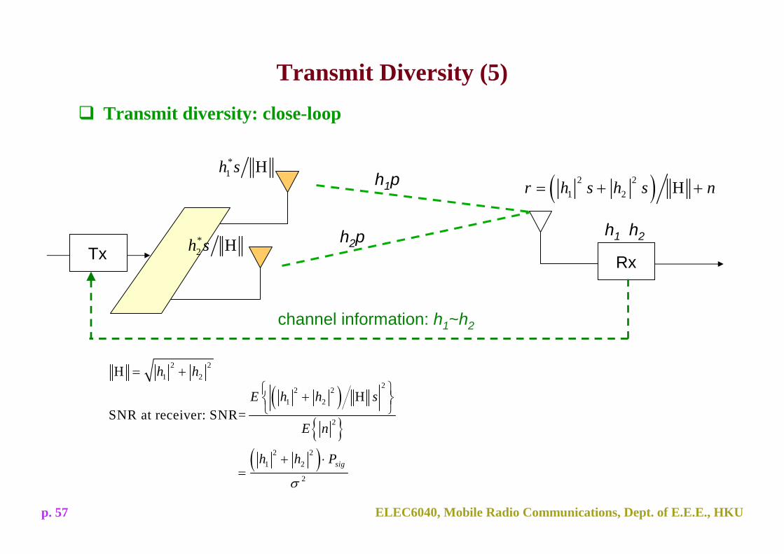
Transmit Diversity (5)Transmit diversity: close-loop
Tx Rx
h1p
h2ph1 h2
channel information: h1~h2
( )2 21 2 Hr h s h s n= + +
*1 Hh s
*2 Hh s
( ){ }
( )
22 21 2
2
2 21 2
2
HSNR at receiver: SNR=
sig
E h h s
E n
h h P
σ
⎧ ⎫+⎨ ⎬⎩ ⎭
+ ⋅=
2 21 2H h h= +

ELEC6040, Mobile Radio Communications, Dept. of E.E.E., HKUp. 58
Transmit Diversity (6)Performance comparison– two transmit antennas, BPSK modulation– identical independent distributed (i.i.d.) Rayleigh fading channel
( )2 21 2
alamouti 2SNR =2
sigh h P
σ
+ ⋅
( )2 21 2
tran_MRC 2SNRsigh h P
σ
+ ⋅=

ELEC6040, Mobile Radio Communications, Dept. of E.E.E., HKUp. 59
Handover (1)
Intra-mode handover– FDD mode– relies on the Ec/N0 measurement performed on the common pilot channel (CPICH)– can be soft handover, softer handover or hard handover– soft handover needs relative timing information between the cells. BSs in WCDMA
is asynchronous; timing adjustment is needed to carry out coherent combining in the Rake receiver in soft handover
Inter-mode handover– Dual-mode FDD-TDD terminals operating in FDD handover to the TDD mode
Inter-system handover– Handover between UTRA (WCDMA) and GSM systems, UTRA (WCDMA) and
Multi-carrier CDMA systems

ELEC6040, Mobile Radio Communications, Dept. of E.E.E., HKUp. 60
Handover (2)SSDT (site selection diversity transmit power control)– is a macro diversity method in soft handover mode
Benefits of SSDT– only one BS is transmitting signals to the MS=>reduce the interference caused by
multiple transmissions in a soft handover mode– when multiple BSs transmit to the same signals to the MS, a number of Rake fingers
are needed; if only one BS is considered, less fingers are needed– no power imbalance problem due to power control command reception error
Old BS
New BS
• Soft Handoff
New BS
1. The MS selects one of the cells from its active set to be primary and others non-primary2. Each cell is assigned a temporary identification (ID). MS periodically informs a primary cell ID to the connecting cells3. The non-primary cells switch off the transmission power
ELEC6040, Mobile Radio Communications, Dept. of E.E.E., HKUp. 61
Power Control
Fast closed loop power control (inner loop power control)– one command per slot (1500Hz) (IS-95: 800Hz)– basic power adjustment step size: 1dB– applied to both uplink and downlink
Open loop power control– applied only prior to initiating the transmission on the RACH or CPCH (uplink)– adjust the transmit power on uplink based on the measurement on downlink– not very accurate: variation in the component properties, impact of environment,
different frequencies– in IS-95, being active in parallel with close loop power control, allow corner effects
or other sudden environmental changes to be recovered in UTRA (WCDMA), not needed to be operated simultaneously with fast closed loop power control
ELEC6040, Mobile Radio Communications, Dept. of E.E.E., HKUp. 62
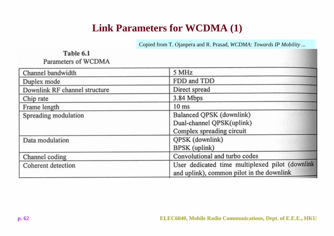
Link Parameters for WCDMA (1)Copied from T. Ojanpera and R. Prasad, WCDMA: Towards IP Mobility ...
ELEC6040, Mobile Radio Communications, Dept. of E.E.E., HKUp. 63
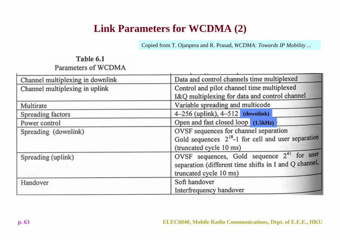
Link Parameters for WCDMA (2)Copied from T. Ojanpera and R. Prasad, WCDMA: Towards IP Mobility ...
(downlink)(1.5kHz)

ELEC6040, Mobile Radio Communications, Dept. of E.E.E., HKUp. 64
Summary - WCDMA vs. GSM Air Interface

ELEC6040, Mobile Radio Communications, Dept. of E.E.E., HKUp. 65
Summary - WCDMA vs. IS-95 Air Interface
ELEC6040, Mobile Radio Communications, Dept. of E.E.E., HKUp. 66
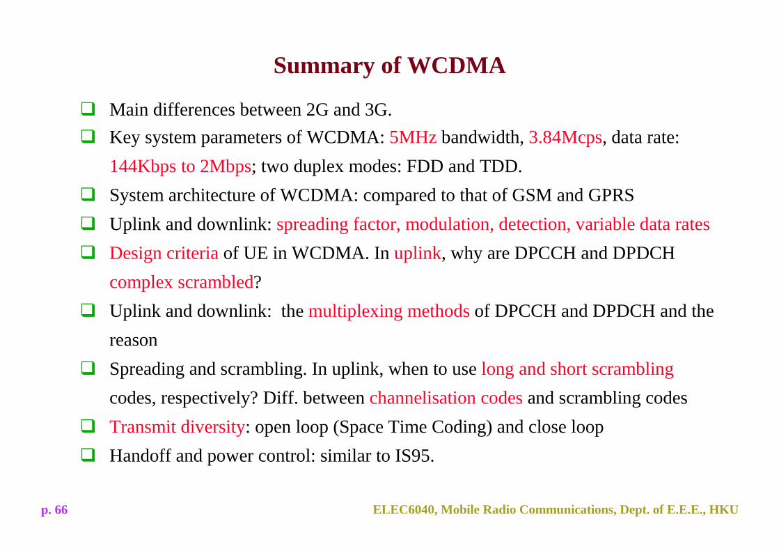
Main differences between 2G and 3G.Key system parameters of WCDMA: 5MHz bandwidth, 3.84Mcps, data rate: 144Kbps to 2Mbps; two duplex modes: FDD and TDD. System architecture of WCDMA: compared to that of GSM and GPRSUplink and downlink: spreading factor, modulation, detection, variable data ratesDesign criteria of UE in WCDMA. In uplink, why are DPCCH and DPDCH complex scrambled?Uplink and downlink: the multiplexing methods of DPCCH and DPDCH and the reasonSpreading and scrambling. In uplink, when to use long and short scramblingcodes, respectively? Diff. between channelisation codes and scrambling codesTransmit diversity: open loop (Space Time Coding) and close loopHandoff and power control: similar to IS95.
Summary of WCDMA
ELEC6040, Mobile Radio Communications, Dept. of E.E.E., HKUp. 67
CDMA2000
ELEC6040, Mobile Radio Communications, Dept. of E.E.E., HKUp. 68
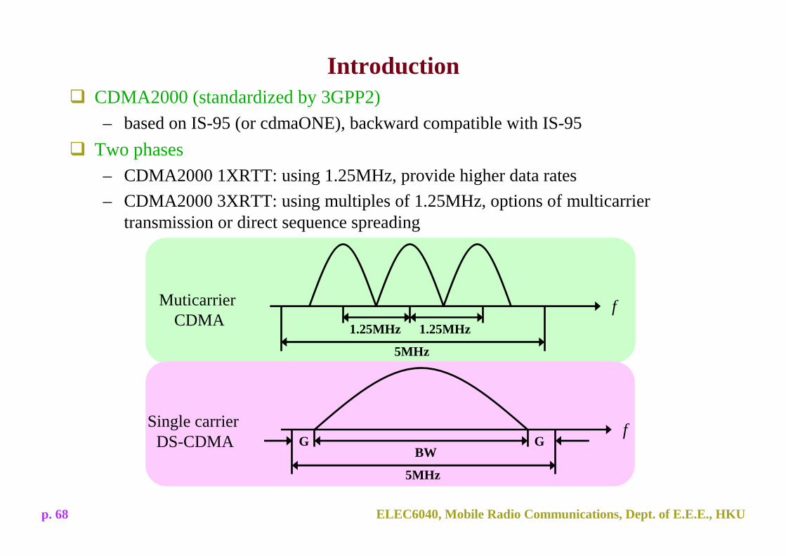
IntroductionCDMA2000 (standardized by 3GPP2)– based on IS-95 (or cdmaONE), backward compatible with IS-95
Two phases– CDMA2000 1XRTT: using 1.25MHz, provide higher data rates– CDMA2000 3XRTT: using multiples of 1.25MHz, options of multicarrier
transmission or direct sequence spreading
MuticarrierCDMA
5MHz
1.25MHz 1.25MHz
f
Single carrier DS-CDMA
5MHz
BW
fG G

ELEC6040, Mobile Radio Communications, Dept. of E.E.E., HKUp. 69
System Architecture
New functional elements for packet
data service

ELEC6040, Mobile Radio Communications, Dept. of E.E.E., HKUp. 70
Network Elements (1)Mobile Station (MS)– all functionalities of IS-95 terminals + additional features and capabilities to support
new packet data services + enhanced signaling messagesBase Station (BS)– base transceiver station (BTS) + base station controller (BSC)– compared to IS-95: similar basic functionalities, significant hardware and software
changes to provide multimedia servicesPacket Control Function (PCF)– belongs to radio access network– manages the buffering and relay of packet between the BS and the PDSN
Packet Data Service Node (PDSN)– acting as a foreign agent (FA), providing routing services– managing the radio-packet (R-P) interface and PPP sessions for mobile users– Initiating authentication, authorization and accounting for the mobile user to the
AAA server and receiving service parameters for the mobile user from the AAA server

ELEC6040, Mobile Radio Communications, Dept. of E.E.E., HKUp. 71
Network Elements (2)
Home Agent (HA)– mobile IP registration– packet forwarding
Authentication, Authorization and Accounting (AAA)– authentication: user and device identity verification for network access and user-
based QoS requests, authentication to establish dynamic security associations between network entities
– authorization: has access to subscribers profiles, the device register and the operator's policy repository; decides whether a user or device is authorized for a particular service with a specific QoS
– accounting: collecting and storing the billing-related data concerning the offered services, their associated QoS and the multimedia resources requested and used y individual subscribers

ELEC6040, Mobile Radio Communications, Dept. of E.E.E., HKUp. 72
Forward Channels
Common channels
Pilot channels: Pilot Channel (F-PICH)Transmit Diversity Pilot Channel (F-TDPICH)Auxiliary Pilot Channel (F-APICH)Auxiliary Transmit Diversity Channel (F-ATDPICH)
Synchronization Channel (F-SYNCH)Broadcast channel: Broadcast Control Channel (F-BCCH)Paging channels: Paging Channel (F-PCH)
Quick Paging Channel (F-QPCH)Control channels: Packet Data Control Channel (F-PDCCH)
Common Assignment Channel (F-CACH)Common Power Control Channel (F-CPCCH)Common Control Channel (F-CCCH)
Dedicated channels
Fundamental Channel (F-FCH)Supplemental Channel (F-SCH)Dedicated Control Channel (F-DCCH)Auxiliary Pilot Channel (F-APICH)
Trafficchannels
Sharedchannel Packet Data Channel (F-PDCH) Traffic
channel
Radio Interface - Physical Layer
ELEC6040, Mobile Radio Communications, Dept. of E.E.E., HKUp. 73
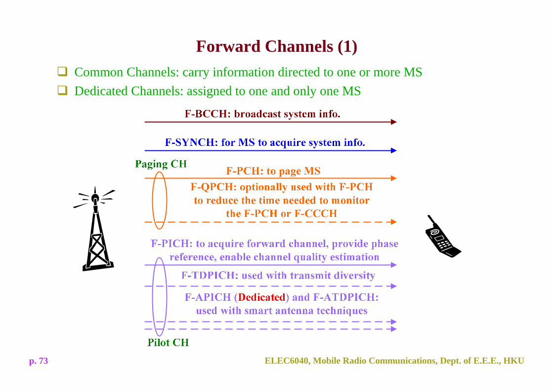
Forward Channels (1)Common Channels: carry information directed to one or more MSDedicated Channels: assigned to one and only one MS

ELEC6040, Mobile Radio Communications, Dept. of E.E.E., HKUp. 74
Forward Channels (2)
F-PDCH– the only shared channel– similar to a dedicated channel in many physical characteristics, only a single MS
decodes this channel at a time– assigned to a MS by Layer 2 signaling, short assignment: 1.25, 2.5 or 5ms
F-FCH and F-SCH: user data
F-PDCCH: signaling support for F-PDCHF-CACH and F-CPCCH: support a
form of reverse link access procedure(reservation access mode)
F-DCCH: control + user data
F-PDCH: bursty data, high speed, non-real time
Traffic CH
Control CH

ELEC6040, Mobile Radio Communications, Dept. of E.E.E., HKUp. 75
Forward Channels (3)Functional Construction– Modulation, coding and spreading (MCS) characteristics of physical channels vary
greatly as the standard evolved– In case of traffic channels, the fundamental functional building blocks are common
to all channelsFunctional Block Diagram for Forward Traffic Channels
Block encoder
Conv. orTurbo
encoder
Symbol repetition or puncturing
Interleaver
Modulator Orthogonal spreading
Quadraturespreading Filter
source bits
long code
Scrambling
cos(2πfct)
sin(2πfct)
s(t)
CRC: Error detection Rate matching
PNI PNQ

ELEC6040, Mobile Radio Communications, Dept. of E.E.E., HKUp. 76
Functional Blocks (1)Forward link data scrambling– provides privacy of communication: scrambling sequences unique among users– uses a long PN sequence, maximum length linear shift sequences (MLLSRS),
sequence period 242-1– applies a user-specific (for dedicated channels) or code channel-specific (for
common channels) mask to get a unique sequence– the masking process effectively shifts the MLLSRS, resulting in a unique long PN
sequence
user-specific or code channel-specific

ELEC6040, Mobile Radio Communications, Dept. of E.E.E., HKUp. 77
Functional Blocks (2)Forward link modulation– forward link: strong common pilot signal, higher order modulation
BPSKF-SYNCH
un-modulatedF-PICH
QPSKAll Others
adaptive modulation with QPSK, 8PSK, 16QAMF-PDCH
BPSKF-PCH
Modulation schemeForward link channel
known pilot symbols
important, low BER
to provide higher data rate when channel is good

ELEC6040, Mobile Radio Communications, Dept. of E.E.E., HKUp. 78
Functional Blocks (3)
QPSK vs. BPSK– Advantages of QPSK: higher bandwidth efficiency, increase coding gain

ELEC6040, Mobile Radio Communications, Dept. of E.E.E., HKUp. 79
Functional Blocks (4)QPSK vs. BPSK (cont'd)– Disadvantages of QPSK: more sensitive to inaccurate carrier-phase recovery, larger
SINR degradation– Advantages of BPSK: less sensitive to inaccurate carrier-phase recovery, smaller
SINR degradation
– Forward link: carrier phase estimated by higher powered F-PICH, resulting in small phase error => QPSK is better than BPSK
carrier phaseerror
decisionerror
carrier phaseerror
correctdecision
QPSK BPSK

ELEC6040, Mobile Radio Communications, Dept. of E.E.E., HKUp. 80
Functional Blocks (5)Forward link orthogonal spreading– orthogonal code: Walsh code– spreading factor: 4~128, exceptions: F-APICH and F-ATDPICH: 512– achieves bandwidth expansion
– at most 61 length-64 Walsh codes for traffic transmission
Source: V. K. Garg, IS-95 CDMA and cdma2000
ELEC6040, Mobile Radio Communications, Dept. of E.E.E., HKUp. 81
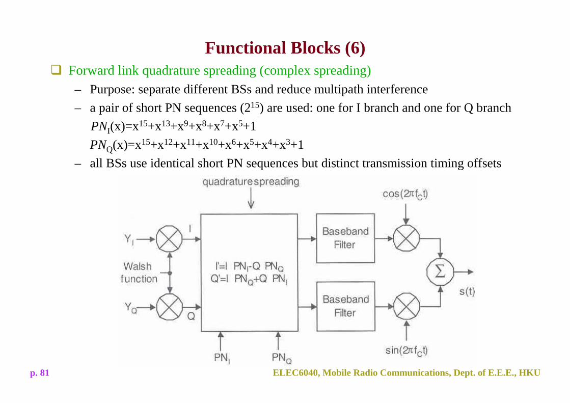
Functional Blocks (6)Forward link quadrature spreading (complex spreading)– Purpose: separate different BSs and reduce multipath interference– a pair of short PN sequences (215) are used: one for I branch and one for Q branch
PNI(x)=x15+x13+x9+x8+x7+x5+1PNQ(x)=x15+x12+x11+x10+x6+x5+x4+x3+1
– all BSs use identical short PN sequences but distinct transmission timing offsets

82ELEC6040, Mobile Radio Communications, Dept. of E.E.E., HKUp. 82
Input power
Out
put p
ower
Operationpoint
Peak
Back-off
AveragePeak
time
Why is complex spreading necessary?
Peak-to-average ratio
The power amplifier can be used more efficiently by reducing the peak-to-average ratio, resulting in reducing the power consumption of power amplifier

83ELEC6040, Mobile Radio Communications, Dept. of E.E.E., HKUp. 83
( )kk tE φω +0cos
( )kk tE φω +− 0sin
)(, nCg kPk ⋅
)()( , nCmjD kDk ⋅
)()( njSnS QI +
( )tSk
)(th
)(th
)Re(⋅
)Im(⋅complex spreading
It can reduce the signal envelope variation, due to the correlation of Re(.) and Im(.)
Transmitter Model of Complex Spreading

84ELEC6040, Mobile Radio Communications, Dept. of E.E.E., HKUp. 84
( )kk tE φω +0cos
( )kk tE φω +− 0sin
)(, nCg kPk ⋅
)()( , nCmD kDk ⋅
)(nSI( )tSk
)(th
)(th
)(nSQ
Transmitter Model of Dual-Channel Spreading
I and Q channels are uncorrelated.

85ELEC6040, Mobile Radio Communications, Dept. of E.E.E., HKUp. 85
Normalized deviation of complex spreading and dual-channel spreading signals
00.2
0.25
0.3
0.35
0.4
0.45
I/Q unbalanced power ratio -- g
ND
50.2 0.4 0.6 0.8 1.25 1.67 2.51 ∞
Dual-channel spreadingComplex spreading
Normalized Deviation of Envelope

ELEC6040, Mobile Radio Communications, Dept. of E.E.E., HKUp. 86
Forward Link Transmit DiversityTransmit diversity– two antennas are used to transmit the same code channel– achieve increased diversity gain, improve forward-link performance
Two modes– Orthogonal Transmit Diversity (OTD): take advantage of the decoding process,
achieve diversity in the Viterbi decoder path metrics, code dependent, the more powerful the code, the better the performance
– Space Time Spreading (STS): based on Alamouti code
0T2T
dk(n+1) dk
(n)
OTD encoder
0T2T
dk(n) dk
(n)
-dk(n+1) dk
(n+1)
0T2T
dk(n+1) dk
(n)
STS encoder
0T2T
dk(n)+ [dk
(n+1)]*
dk(n+1)+ [dk
(n)]*
dk(n)- [dk
(n+1)]*
dk(n+1)- [dk
(n)]*
Source: A. Dabak, S. Hosur, T. Schmidl, and C. Sengupta, “A comparison of open loop transmit diversity schemes for third generation wireless systems,” in Proc. WCNC, vol. 1, 2000.

ELEC6040, Mobile Radio Communications, Dept. of E.E.E., HKUp. 87
Reverse Channels (1)
Reverse Channels
Common channels
Access Channel (R-ACH)Enhanced Access Channel (R-EACH)Common Control Channel (R-CCCH)
Dedicated channels
Fundamental Channel (R-FCH)Supplemental Channel (R-SCH)Dedicated Control Channel (R-DCCH)Pilot Channel (R-PICH)Channel Quality Indicator Channel (R-CQICH)Acknowledgment Channel (R-ACKCH)
Trafficchannels

ELEC6040, Mobile Radio Communications, Dept. of E.E.E., HKUp. 88
Reverse Channels (2)
Common Channels– employ a base station-specific PN sequence, simultaneous transmissions by multiple
MSs on the same common channel cannot be discriminated, possibility for collisions– contention-based channels, use specialized random access protocols– carry signaling in support of registration, authentication, call origination, or small
amounts of user data
Dedicated Channels– spread by mobile-specific PN sequences, can be discriminated at BS– R-FCH, R-DCCH: carry signaling or user traffic– R-SCH: carry only user traffic– R-CQICH and R-ACKCH: in support of F-PDCH (Forward-Packet Data CHannels)

ELEC6040, Mobile Radio Communications, Dept. of E.E.E., HKUp. 89
Reverse Channels (3)Functional Block Diagram for Reverse Traffic Channels
Block encoder
Conv. orTurbo
encoder
Symbol repetition or puncturing
Interleaver
Orthogonal spreading
Quadraturespreading Filter
source bits
cos(2πfct)
sin(2πfct)
s(t)
CRC: Error detection Rate matching
long code
PNI PNQOther channels' modulation symbols

ELEC6040, Mobile Radio Communications, Dept. of E.E.E., HKUp. 90
Functional Blocks (1)Reverse link modulation– reverse link: dedicated pilot channel, code-multiplexed with data symbols, limited
transmit power, carrier-phase estimation error is large => BPSK modulationReverse link orthogonal spreading– orthogonal code: Walsh code, spreading factor: 2~64

ELEC6040, Mobile Radio Communications, Dept. of E.E.E., HKUp. 91
Functional Blocks (2)W1,0
W2,0 W2,1
W4,0 W4,2
W8,0 W8,4
W16,0 W16,8
W8,2 W8,6
W4,1 W4,3
W8,1 W8,5 W8,3 W8,7
W32,0W32,16
W64,0W64,32 W64,16 W64,48
W16,12W16,4 W16,2W16,10 W16,6W16,14 W16,1 W16,9 W16,5W16,13 W16,3W16,11 W16,7W16,15
R-SCH 1R-SCH 2
R-PICH R-DCCH R-FCHR-EACH or
R-CCCHR-CQICHR-ACKCH
Tree Structure of Walshfunctions for reverse
physical channels

ELEC6040, Mobile Radio Communications, Dept. of E.E.E., HKUp. 92
Functional Blocks (3)Reverse link quadrature spreading– Purpose: separate different MSs and code channels– a pair of short PN sequences (215) are used: one for I branch and one for Q branch– a long code mask is needed to discriminate users' signals at the BS
PNI' PNQ'Same as
those used in forward
link
PNI' PNQ'

ELEC6040, Mobile Radio Communications, Dept. of E.E.E., HKUp. 93
Handoff (1)Hard handoff– interfrequency handoff– CDMA2000: operate on multiple carriers, sometimes require a MS's handoff to a
different carrierSoft handoff– forward link: multiple BSs transmit identical traffic channels data symbols, the MS
combines the demodulated signals prior to frame decoding, spatial diversity– reverse link: multiple BSs receive same data symbols from the MS, decode
independently and send to BSC, BSC chooses the one with the highest quality, selection combining, weaker spatial diversity
Softer handoff– forward link: same as that in soft handoff– reverse link: some BSs are with the same BTS, the BTS can combine the
demodulated signals prior to frame decoding

ELEC6040, Mobile Radio Communications, Dept. of E.E.E., HKUp. 94
Handoff (2)Softer handoff– when MS has n+m BSs in the active set, n of them corresponds to different BTSs,
the MS is in n-way soft, m-way softer handoff
BTS1BTS2
two way soft handoff
one way soft two way softer
handoff
two way softer handoff

ELEC6040, Mobile Radio Communications, Dept. of E.E.E., HKUp. 95
Power Control (1)Review– Power control is especially important in CDMA systems.
Reverse link power control– consists of open loop and close loop power controls, two control loops operate
concurrently (different to WCDMA)– Open loop: long-term channel variation (distance, shadowing)– Close loop: short-term channel variation (fast fading) and open loop inaccuracy
Reverse link open loop power control– Principle: the larger the received signal strength, the smaller the transmission loss
between MS and BS is expected to be, and vice versa – MS sets its transmit power inversely proportional to the total received power

ELEC6040, Mobile Radio Communications, Dept. of E.E.E., HKUp. 96
Power Control (2)Reverse link close loop power control– cooperate with BS: inner loop and outer loop– MS receives power control commands on the F-PCSCH– power control step size: 1dB, frequency: 800Hz (same as IS-95)
close loop power control - inner loop– BS estimates the received SNR on R-PICH, compares it against that allocated to the
MS (target), and sets the power control bitclose loop power control - outer loop– tracks QoS and adjust the R-PICH target SNR used by the inner loop– A measure of QoS: R-FCH FER
close loop imperfections– power control commands received in error: power control commands are transmitted
uncoded to minimize the turnaround time– incorrect SNR estimate: the received R-PICH SNR is only on average equal to the
target but exhibits fluctuations that are more pronounced when the MS moves at high speed (fast fading)
ELEC6040, Mobile Radio Communications, Dept. of E.E.E., HKUp. 97
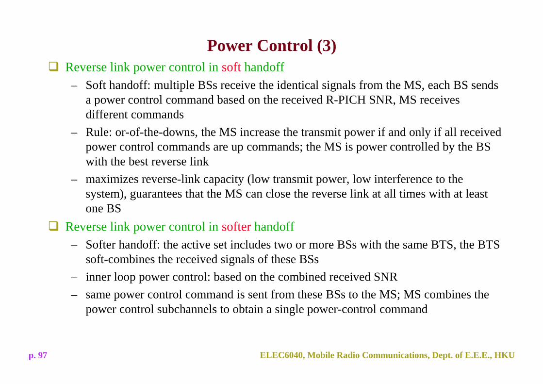
Power Control (3)Reverse link power control in soft handoff– Soft handoff: multiple BSs receive the identical signals from the MS, each BS sends
a power control command based on the received R-PICH SNR, MS receives different commands
– Rule: or-of-the-downs, the MS increase the transmit power if and only if all received power control commands are up commands; the MS is power controlled by the BS with the best reverse link
– maximizes reverse-link capacity (low transmit power, low interference to the system), guarantees that the MS can close the reverse link at all times with at least one BS
Reverse link power control in softer handoff– Softer handoff: the active set includes two or more BSs with the same BTS, the BTS
soft-combines the received signals of these BSs– inner loop power control: based on the combined received SNR– same power control command is sent from these BSs to the MS; MS combines the
power control subchannels to obtain a single power-control command

ELEC6040, Mobile Radio Communications, Dept. of E.E.E., HKUp. 98
Power Control (4)Forward link power control– consists of open loop and close loop power controls (different to WCDMA)
Forward link open-loop power control– used when the forward traffic channel is initialized (e.g., call setup), the BS selects
its initial transmit power level and initializes the code channel gain, no reference, implementation dependent
– simplest solution: initialize the transmit power to the maximum allowable level to maximize call setup reliability
– done once and only once at call set up (different to reverse link)Forward link close-loop power control– activated when the MS receives two consecutive good frames at call set up and starts
reverse link transmission– BS receives power control commands on the R-PCSCH and adjusts the transmit
power accordingly

ELEC6040, Mobile Radio Communications, Dept. of E.E.E., HKUp. 99
Power Control (5)
Forward link close-loop power control: inner loop– MS estimates the SNR of received F-FCH, compares it against the target value, and
sets the power control command– power control rate: 800Hz
Forward link close-loop power control: outer loop– BS sends the target F-FCH FER to MS; MS measures the FER, compares it against
the target FER, and decides the target SNR value of F-FCH– implementation dependent
Forward link power control in soft handoff– MS sends the power control command to multiple BSs in the handoff active set– due to transmission error, some BSs may receive an up command while others may
get a down command => a drift of the F-FCH transmit power of one BS relative to the other
– degrades MS receiver performance => researches on reducing the transmit power drift

ELEC6040, Mobile Radio Communications, Dept. of E.E.E., HKUp. 100
Summary - Link Parameters for cdma2000
Copied from T. Ojanpera and R. Prasad, WCDMA: Towards IP Mobility ...

ELEC6040, Mobile Radio Communications, Dept. of E.E.E., HKUp. 101
Summary - Link Parameters for cdma2000 (Con't)
cdma2000 1x cdma2000 3x
2 - 512

ELEC6040, Mobile Radio Communications, Dept. of E.E.E., HKUp. 102
Comparison between WCDMA & cdma2000 (1)
Adapted from T. Ojanpera and R. Prasad, “An overview of air interface multiple access for IMT-2000 / UMTS,” IEEE Communication Magazine, vol. 36, p. 85, Sep. 1998.
3.84Mchips/s
WCDMA CDMA20005MHz 1.25, 5MHz
1.2288 Mchips/s for direct spreading3.6864 Mchips/s for multicarrier spreading

ELEC6040, Mobile Radio Communications, Dept. of E.E.E., HKUp. 103
Comparison between WCDMA & cdma2000 (2)
Adapted from T. Ojanpera and R. Prasad, “An overview of air interface multiple access for IMT-2000 / UMTS,” IEEE Communication Magazine, vol. 36, p. 85, Sep. 1998.
WCDMA CDMA2000
( 3.84Mchips/s)
( 1.5KHz)
215
2-512

ELEC6040, Mobile Radio Communications, Dept. of E.E.E., HKUp. 104
Summary of cdma2000
cdma2000 1xRTT and 3xRTT: bandwidth: 1.25MHz and 5MHz, respectively.cdma2000 system architecture: compare to that of IS-95 and WCDMAUnderstand the concepts of common channel, dedicated channel and shared channel. Detailed names and functions of specific channels: not requested.Why do different channels employ different modulation schemes? Comparison between QPSK and BPSK.Understand complex spreading and dual channel spreading: diagrams, comparisons.Transmit diversity: compared to that of WCDMA.Handoff and power control: similar to IS95 with some new operations.Measures or techniques employed in physical layer (uplink/downlink) of cdma2000 to increase the transmission rate compared to IS95: spreading factors, channel coding, modulation, multi-code transmission.