Embed Size (px)
Citation preview
Chinese Journal of Aeronautics, (2014),27(5): 1171–1179
Chinese Society of Aeronautics and Astronautics& Beihang University
Chinese Journal of Aeronautics
Changing law of launching pitching angular
velocity of rotating missile
* Corresponding author at: Department of Mechanics and Engi-
neering Science, Fudan University, Shanghai 200433, China. Tel.: +86
21 24185555.E-mail addresses: [email protected] (G. Liu), Zhengts@
fudan.edu.cn (T. Zhen).
Peer review under responsibility of Editorial Committee of CJA.
Production and hosting by Elsevier
http://dx.doi.org/10.1016/j.cja.2014.09.0041000-9361 ª 2014 Production and hosting by Elsevier Ltd. on behalf of CSAA & BUAA. Open access under CC BY-NC-ND license.
Liu Guang a,b,*, Xu Bin a,b, Jiao Xiaojuan a, Zhen Tiesheng a
a Department of Mechanics and Engineering Science, Fudan University, Shanghai 200433, Chinab Shanghai Electro-Mechanical Engineering Institute, Shanghai 201109, China
Received 22 March 2013; revised 2 April 2014; accepted 1 August 2014Available online 28 September 2014
KEYWORDS
LPAV;
MFBD;
Modeling;
Rotating missile;
Simulation;
Virtual prototyping
Abstract In order to provide accurate launching pitching angular velocity (LPAV) for the exterior
trajectory optimization design, multi-flexible body dynamics (MFBD) technology is presented to
study the changing law of LPAV of the rotating missile based on spiral guideway. AnMFBD virtual
prototypemodel of the rotatingmissile launching system is built usingmulti-body dynamicsmodeling
technology based on the built flexible body models of key components and the special force model.
The built model is verified with the frequency spectrum analysis.With the flexible body contact theory
and nonlinear theory of MFBD technology, the research is conducted on the influence of a series of
factors on LPAV, such as launching angle change, clearance between launching canister and missile,
thrust change, thrust eccentricity andmass eccentricity, etc. Through this research, some useful values
of the key design parameters which are difficult to be measured in physical tests are obtained. Finally,
a simplified mathematical model of the changing law of LPAV is presented through fitting virtual test
results using the linear regression method and verified by physical flight tests. The research results
have important significance for the exterior trajectory optimization design.ª 2014 Production and hosting by Elsevier Ltd. on behalf of CSAA & BUAA.Open access under CC BY-NC-ND license.
1. Introduction
A rotating missile is a terminal defense weapon with quickreactions, high launching efficiency and simple structure, etc.,
the main function of which is to intercept and attack sea-
skimming flight anti-ship missiles and high-speed aircrafts.The missile has important practical significance to the coastaldefense of the South China Sea. When the missile is launched,
the empennage seat is used as a support and contact with theside of spiral guideway in the launching canister so that themissile moves along with the spiral guideway to achieve
the rotation movement of the missile launching. In the processof launching the rotating missile, its launching pitchingangular velocity (LPAV) must be some dispersed and difficultto be determined due to a variety of influencing factors such
as launching angle change, clearance between launchingcanister and missile, thrust change, thrust eccentricity andmass eccentricity, etc.
1172 G. Liu et al.
LPAV is an important initial parameter in the exterior tra-jectory design.1 The past flight test results prove that theimproper parameter value would result in large deviation
between theoretical and flight test trajectories, and lead toflight test failure eventually. Therefore, the changing law ofLPAV has some significance for the exterior trajectory optimi-
zation design. In order to find out the changing law of LPAVof the rotating missile and provide an accurate initial parame-ter for the exterior trajectory design, it is of necessity to make
dynamic modeling and simulation of the rotating missilelaunching process.2–4 The traditional mathematic modelingmethod of launching dynamics is very tedious and the builtmodel is largely simplified, therefore it cannot accurately con-
sider the complex collision between the launching canister andthe missile, and even the elastic vibration, large deformationand nonlinear vibration of the missile, the launching canister
and the rack.5–7 Multi-rigid body launching dynamics model-ing and simulation technology provides an effective solutionto the rotating missile development problems, which considers
only the complex collision between the launching canister andthe missile but the vibration and deformation of the missilebody, the launching canister and the rack.8,9 The past flight
test results prove that LPAV from multi-rigid body launchingdynamics simulation cannot satisfy the exterior trajectorydesign requirement. Rigid-flexible coupling launching dynam-ics modeling and simulation technology based on the Craig-
Bampton modal synthesis method considers only the linearelastic deformation of parts, but the collision between flexiblebodies, and not even the larger deformation and nonlinear
analysis.10–14 Therefore, multi-flexible body dynamics(MFBD) modeling and simulation technology is presented tosolve the above problems.15 MFBD technology enables design-
ers to simulate the mechanical environment more really atrotating missile launching.
Therefore, in this paper the rotating missile launching sys-
tem is taken as an example, and its multi-body dynamicsmodel is built based on the MFBD technology using the modalsynthesis method and the nodal method. Based on the builtmodel, the research is conducted on the influence of a series
of factors on LPAV such as launching angle change, clearance
Fig. 1 Topological structu
between launching canister and missile, thrust change, thrusteccentricity and mass eccentricity, etc., using the flexible bodycontact theory and the nonlinear theory of MFBD technology
and we obtain some significant values of the key design param-eters which are difficult to be measured in physical tests.Finally, a simplified mathematical model of the changing law
of LPAV is presented through fitting the virtual test resultsby means of the linear regression method and is verified byphysical flight tests. The research results have important signif-
icance for the exterior trajectory optimization design.
2. Components of launching system and analysis of launching
process
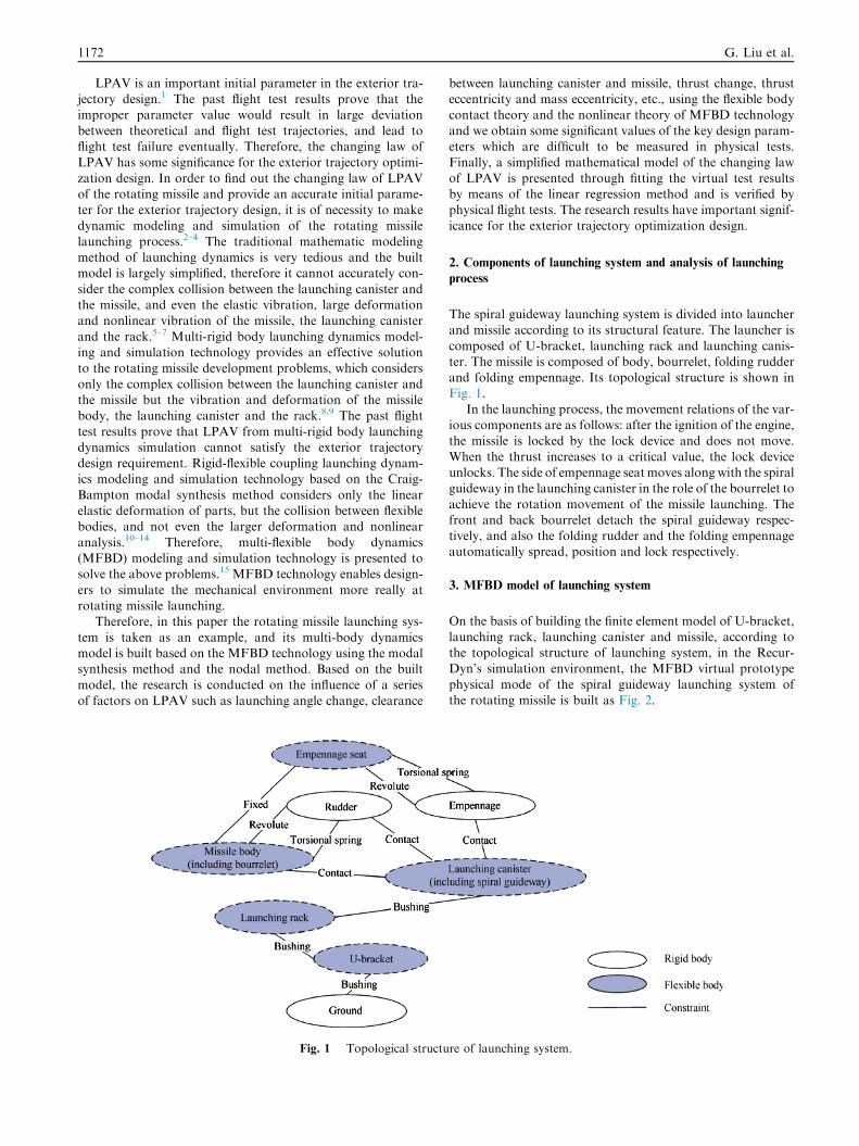
The spiral guideway launching system is divided into launcherand missile according to its structural feature. The launcher is
composed of U-bracket, launching rack and launching canis-ter. The missile is composed of body, bourrelet, folding rudderand folding empennage. Its topological structure is shown inFig. 1.
In the launching process, the movement relations of the var-ious components are as follows: after the ignition of the engine,the missile is locked by the lock device and does not move.
When the thrust increases to a critical value, the lock deviceunlocks. The side of empennage seat moves along with the spiralguideway in the launching canister in the role of the bourrelet to
achieve the rotation movement of the missile launching. Thefront and back bourrelet detach the spiral guideway respec-tively, and also the folding rudder and the folding empennageautomatically spread, position and lock respectively.
3. MFBD model of launching system
On the basis of building the finite element model of U-bracket,launching rack, launching canister and missile, according tothe topological structure of launching system, in the Recur-Dyn’s simulation environment, the MFBD virtual prototype
physical mode of the spiral guideway launching system ofthe rotating missile is built as Fig. 2.
re of launching system.
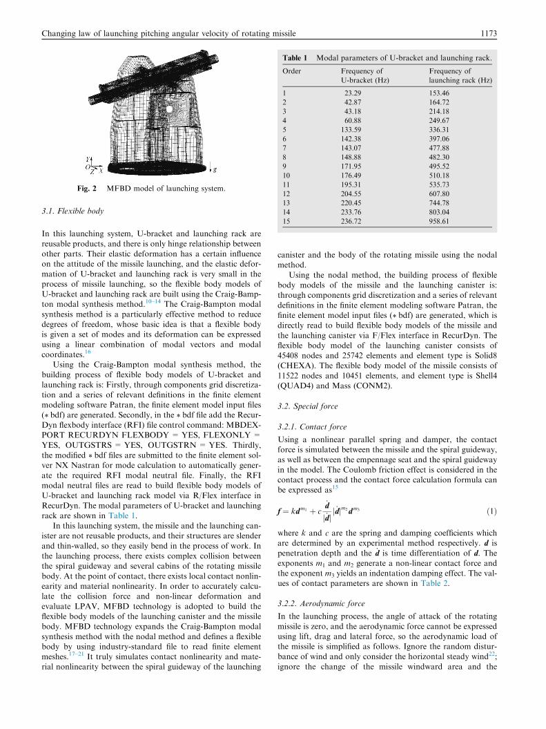
Fig. 2 MFBD model of launching system.
Table 1 Modal parameters of U-bracket and launching rack.
Order Frequency of
U-bracket (Hz)
Frequency of
launching rack (Hz)
1 23.29 153.46
2 42.87 164.72
3 43.18 214.18
4 60.88 249.67
5 133.59 336.31
6 142.38 397.06
7 143.07 477.88
8 148.88 482.30
9 171.95 495.52
10 176.49 510.18
11 195.31 535.73
12 204.55 607.80
13 220.45 744.78
14 233.76 803.04
15 236.72 958.61
Changing law of launching pitching angular velocity of rotating missile 1173
3.1. Flexible body
In this launching system, U-bracket and launching rack are
reusable products, and there is only hinge relationship betweenother parts. Their elastic deformation has a certain influenceon the attitude of the missile launching, and the elastic defor-
mation of U-bracket and launching rack is very small in theprocess of missile launching, so the flexible body models ofU-bracket and launching rack are built using the Craig-Bamp-ton modal synthesis method.10–14 The Craig-Bampton modal
synthesis method is a particularly effective method to reducedegrees of freedom, whose basic idea is that a flexible bodyis given a set of modes and its deformation can be expressed
using a linear combination of modal vectors and modalcoordinates.16
Using the Craig-Bampton modal synthesis method, the
building process of flexible body models of U-bracket andlaunching rack is: Firstly, through components grid discretiza-tion and a series of relevant definitions in the finite elementmodeling software Patran, the finite element model input files
(\Æbdf) are generated. Secondly, in the \Æbdf file add the Recur-Dyn flexbody interface (RFI) file control command: MBDEX-PORT RECURDYN FLEXBODY = YES, FLEXONLY =
YES, OUTGSTRS = YES, OUTGSTRN =YES. Thirdly,the modified \Æbdf files are submitted to the finite element sol-ver NX Nastran for mode calculation to automatically gener-
ate the required RFI modal neutral file. Finally, the RFImodal neutral files are read to build flexible body models ofU-bracket and launching rack model via R/Flex interface in
RecurDyn. The modal parameters of U-bracket and launchingrack are shown in Table 1.
In this launching system, the missile and the launching can-ister are not reusable products, and their structures are slender
and thin-walled, so they easily bend in the process of work. Inthe launching process, there exists complex collision betweenthe spiral guideway and several cabins of the rotating missile
body. At the point of contact, there exists local contact nonlin-earity and material nonlinearity. In order to accurately calcu-late the collision force and non-linear deformation and
evaluate LPAV, MFBD technology is adopted to build theflexible body models of the launching canister and the missilebody. MFBD technology expands the Craig-Bampton modal
synthesis method with the nodal method and defines a flexiblebody by using industry-standard file to read finite elementmeshes.17–21 It truly simulates contact nonlinearity and mate-rial nonlinearity between the spiral guideway of the launching
canister and the body of the rotating missile using the nodalmethod.
Using the nodal method, the building process of flexiblebody models of the missile and the launching canister is:through components grid discretization and a series of relevant
definitions in the finite element modeling software Patran, thefinite element model input files (\Æbdf) are generated, which isdirectly read to build flexible body models of the missile and
the launching canister via F/Flex interface in RecurDyn. Theflexible body model of the launching canister consists of45408 nodes and 25742 elements and element type is Solid8(CHEXA). The flexible body model of the missile consists of
11522 nodes and 10451 elements, and element type is Shell4(QUAD4) and Mass (CONM2).
3.2. Special force
3.2.1. Contact force
Using a nonlinear parallel spring and damper, the contactforce is simulated between the missile and the spiral guideway,as well as between the empennage seat and the spiral guideway
in the model. The Coulomb friction effect is considered in thecontact process and the contact force calculation formula canbe expressed as15
f ¼ kdm1 þ c_d
j _djj _djm2dm3 ð1Þ
where k and c are the spring and damping coefficients whichare determined by an experimental method respectively. d is
penetration depth and the _d is time differentiation of d. Theexponents m1 and m2 generate a non-linear contact force andthe exponent m3 yields an indentation damping effect. The val-ues of contact parameters are shown in Table 2.
3.2.2. Aerodynamic force
In the launching process, the angle of attack of the rotating
missile is zero, and the aerodynamic force cannot be expressedusing lift, drag and lateral force, so the aerodynamic load ofthe missile is simplified as follows. Ignore the random distur-bance of wind and only consider the horizontal steady wind22;
ignore the change of the missile windward area and the
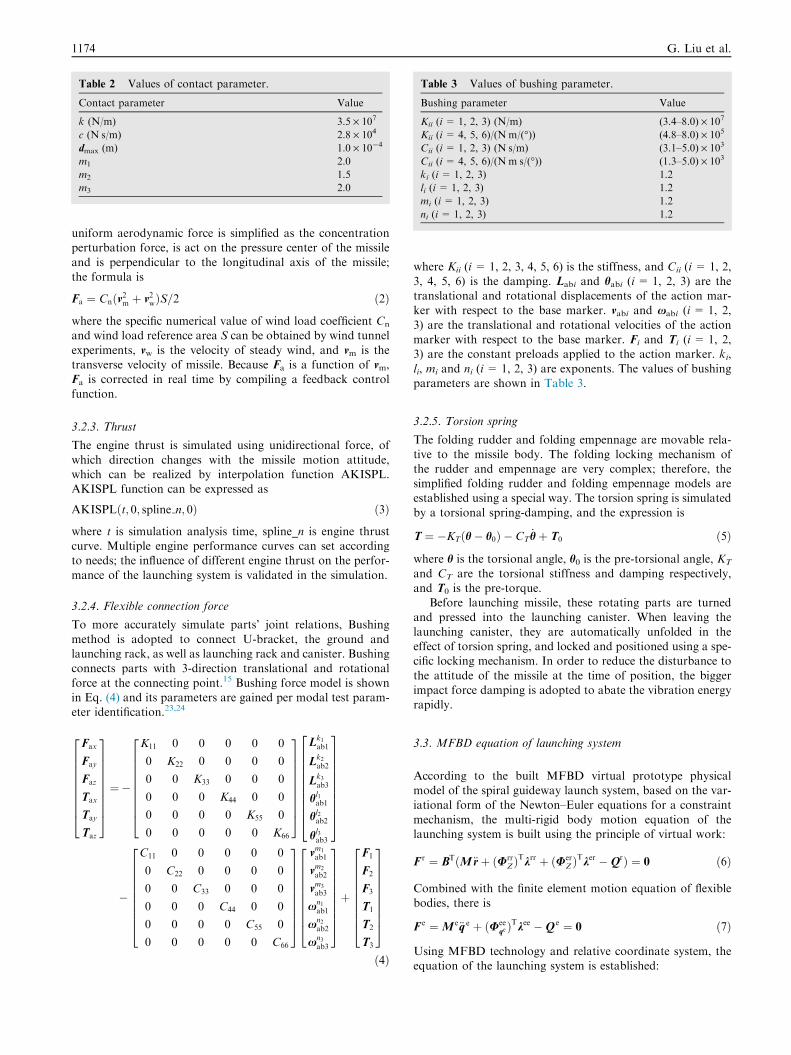
Table 2 Values of contact parameter.
Contact parameter Value
k (N/m) 3.5 · 107
c (NÆs/m) 2.8 · 104
dmax (m) 1.0 · 10�4
m1 2.0
m2 1.5
m3 2.0
Table 3 Values of bushing parameter.
Bushing parameter Value
Kii (i= 1, 2, 3) (N/m) (3.4–8.0) · 107
Kii (i= 4, 5, 6)/(NÆm/(�)) (4.8–8.0) · 105
Cii (i= 1, 2, 3) (NÆs/m) (3.1–5.0) · 103
Cii (i= 4, 5, 6)/(NÆmÆs/(�)) (1.3–5.0) · 103
ki (i= 1, 2, 3) 1.2
li (i= 1, 2, 3) 1.2
mi (i= 1, 2, 3) 1.2
ni (i= 1, 2, 3) 1.2
1174 G. Liu et al.
uniform aerodynamic force is simplified as the concentrationperturbation force, is act on the pressure center of the missile
and is perpendicular to the longitudinal axis of the missile;the formula is
Fa ¼ Cnðv2m þ v2wÞS=2 ð2Þ
where the specific numerical value of wind load coefficient Cn
and wind load reference area S can be obtained by wind tunnel
experiments, vw is the velocity of steady wind, and vm is thetransverse velocity of missile. Because Fa is a function of vm,Fa is corrected in real time by compiling a feedback control
function.
3.2.3. Thrust
The engine thrust is simulated using unidirectional force, of
which direction changes with the missile motion attitude,which can be realized by interpolation function AKISPL.AKISPL function can be expressed as
AKISPLðt; 0; spline n; 0Þ ð3Þ
where t is simulation analysis time, spline_n is engine thrustcurve. Multiple engine performance curves can set accordingto needs; the influence of different engine thrust on the perfor-
mance of the launching system is validated in the simulation.
3.2.4. Flexible connection force
To more accurately simulate parts’ joint relations, Bushing
method is adopted to connect U-bracket, the ground andlaunching rack, as well as launching rack and canister. Bushingconnects parts with 3-direction translational and rotational
force at the connecting point.15 Bushing force model is shownin Eq. (4) and its parameters are gained per modal test param-eter identification.23,24
Fax
Fay
Faz
Tax
Tay
Taz
2666666664
3777777775¼�
K11 0 0 0 0 0
0 K22 0 0 0 0
0 0 K33 0 0 0
0 0 0 K44 0 0
0 0 0 0 K55 0
0 0 0 0 0 K66
2666666664
3777777775
Lk1ab1
Lk2ab2
Lk3ab3
hl1ab1
hl2ab2
hl3ab3
26666666664
37777777775
�
C11 0 0 0 0 0
0 C22 0 0 0 0
0 0 C33 0 0 0
0 0 0 C44 0 0
0 0 0 0 C55 0
0 0 0 0 0 C66
2666666664
3777777775
vm1
ab1
vm2
ab2
vm3
ab3
xn1ab1
xn2ab2
xn3ab3
2666666664
3777777775þ
F1
F2
F3
T1
T2
T3
2666666664
3777777775
ð4Þ
where Kii (i = 1, 2, 3, 4, 5, 6) is the stiffness, and Cii (i = 1, 2,3, 4, 5, 6) is the damping. Labi and habi (i= 1, 2, 3) are thetranslational and rotational displacements of the action mar-ker with respect to the base marker. vabi and xabi (i= 1, 2,
3) are the translational and rotational velocities of the actionmarker with respect to the base marker. Fi and Ti (i = 1, 2,3) are the constant preloads applied to the action marker. ki,
li, mi and ni (i= 1, 2, 3) are exponents. The values of bushingparameters are shown in Table 3.
3.2.5. Torsion spring
The folding rudder and folding empennage are movable rela-
tive to the missile body. The folding locking mechanism ofthe rudder and empennage are very complex; therefore, thesimplified folding rudder and folding empennage models areestablished using a special way. The torsion spring is simulated
by a torsional spring-damping, and the expression is
T ¼ �KTðh� h0Þ � CT_hþ T0 ð5Þ
where h is the torsional angle, h0 is the pre-torsional angle, KT
and CT are the torsional stiffness and damping respectively,and T0 is the pre-torque.
Before launching missile, these rotating parts are turnedand pressed into the launching canister. When leaving the
launching canister, they are automatically unfolded in theeffect of torsion spring, and locked and positioned using a spe-cific locking mechanism. In order to reduce the disturbance to
the attitude of the missile at the time of position, the biggerimpact force damping is adopted to abate the vibration energyrapidly.
3.3. MFBD equation of launching system
According to the built MFBD virtual prototype physicalmodel of the spiral guideway launch system, based on the var-iational form of the Newton–Euler equations for a constraint
mechanism, the multi-rigid body motion equation of thelaunching system is built using the principle of virtual work:
F r ¼ BTðM€rþ ðUrrZÞ
Tkrr þ ðUer
Z ÞTker �QrÞ ¼ 0 ð6Þ
Combined with the finite element motion equation of flexiblebodies, there is
F e ¼M e€q e þ ðUeeqeÞ
Tkee �Q e ¼ 0 ð7Þ
Using MFBD technology and relative coordinate system, theequation of the launching system is established:
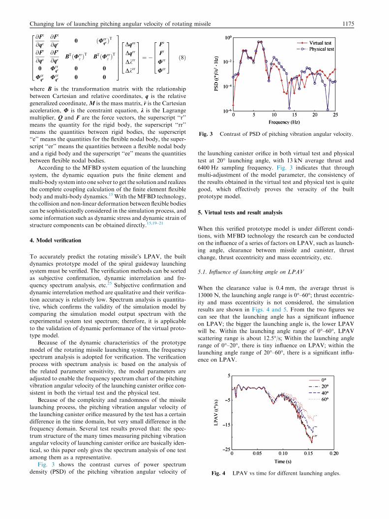
Fig. 3 Contrast of PSD of pitching vibration angular velocity.
Fig. 4 LPAV vs time for different launching angles.
Changing law of launching pitching angular velocity of rotating missile 1175
@Fe
@qe@Fe
@qr0 ðUer
qeÞT
@Fr
@qe@Fr
@qrBTðUrr
z ÞT
BTðUerz Þ
T
0 Urrqr 0 0
Uerqe Uer
qr 0 0
266666664
377777775
Dqee
Dqrr
Dkrr
Dker
26664
37775 ¼ �
Fe
Fr
Urr
Uer
26664
37775 ð8Þ
where B is the transformation matrix with the relationshipbetween Cartesian and relative coordinates, q is the relative
generalized coordinate, M is the mass matrix, €r is the Cartesianacceleration, U is the constraint equation, k is the Lagrangemultiplier, Q and F are the force vectors, the superscript ‘‘r’’
means the quantity for the rigid body, the superscript ‘‘rr’’means the quantities between rigid bodies, the superscript‘‘e’’ means the quantities for the flexible nodal body, the super-
script ‘‘er’’ means the quantities between a flexible nodal bodyand a rigid body and the superscript ‘‘ee’’ means the quantitiesbetween flexible nodal bodies.
According to the MFBD system equation of the launching
system, the dynamic equation puts the finite element andmulti-body system into one solver to get the solution and realizesthe complete coupling calculation of the finite element flexible
body and multi-body dynamics.15 With the MFBD technology,the collision and non-linear deformation between flexible bodiescan be sophisticatedly considered in the simulation process, and
some information such as dynamic stress and dynamic strain ofstructure components can be obtained directly.15,19–21
4. Model verification
To accurately predict the rotating missile’s LPAV, the builtdynamics prototype model of the spiral guideway launching
system must be verified. The verification methods can be sortedas subjective confirmation, dynamic interrelation and fre-quency spectrum analysis, etc.25 Subjective confirmation anddynamic interrelation method are qualitative and their verifica-
tion accuracy is relatively low. Spectrum analysis is quantita-tive, which confirms the validity of the simulation model bycomparing the simulation model output spectrum with the
experimental system test spectrum; therefore, it is applicableto the validation of dynamic performance of the virtual proto-type model.
Because of the dynamic characteristics of the prototypemodel of the rotating missile launching system, the frequencyspectrum analysis is adopted for verification. The verification
process with spectrum analysis is: based on the analysis ofthe related parameter sensitivity, the model parameters areadjusted to enable the frequency spectrum chart of the pitchingvibration angular velocity of the launching canister orifice con-
sistent in both the virtual test and the physical test.Because of the complexity and randomness of the missile
launching process, the pitching vibration angular velocity of
the launching canister orifice measured by the test has a certaindifference in the time domain, but very small difference in thefrequency domain. Several test results proved that: the spec-
trum structure of the many times measuring pitching vibrationangular velocity of launching canister orifice are basically iden-tical, so this paper only gives the spectrum analysis of one testamong them as a representative.
Fig. 3 shows the contrast curves of power spectrumdensity (PSD) of the pitching vibration angular velocity of
the launching canister orifice in both virtual test and physical
test at 20� launching angle, with 13 kN average thrust and6400 Hz sampling frequency. Fig. 3 indicates that throughmulti-adjustment of the model parameter, the consistency ofthe results obtained in the virtual test and physical test is quite
good, which effectively proves the veracity of the builtprototype model.
5. Virtual tests and result analysis
When this verified prototype model is under different condi-tions, with MFBD technology the research can be conducted
on the influence of a series of factors on LPAV, such as launch-ing angle, clearance between missile and canister, thrustchange, thrust eccentricity and mass eccentricity, etc.
5.1. Influence of launching angle on LPAV
When the clearance value is 0.4 mm, the average thrust is
13000 N, the launching angle range is 0�–60�; thrust eccentric-ity and mass eccentricity is not considered, the simulationresults are shown in Figs. 4 and 5. From the two figures wecan see that the launching angle has a significant influence
on LPAV; the bigger the launching angle is, the lower LPAVwill be. Within the launching angle range of 0�–60�, LPAVscattering range is about 12.5�/s; Within the launching angle
range of 0�–20�, there is tiny influence on LPAV; within thelaunching angle range of 20�–60�, there is a significant influ-ence on LPAV.
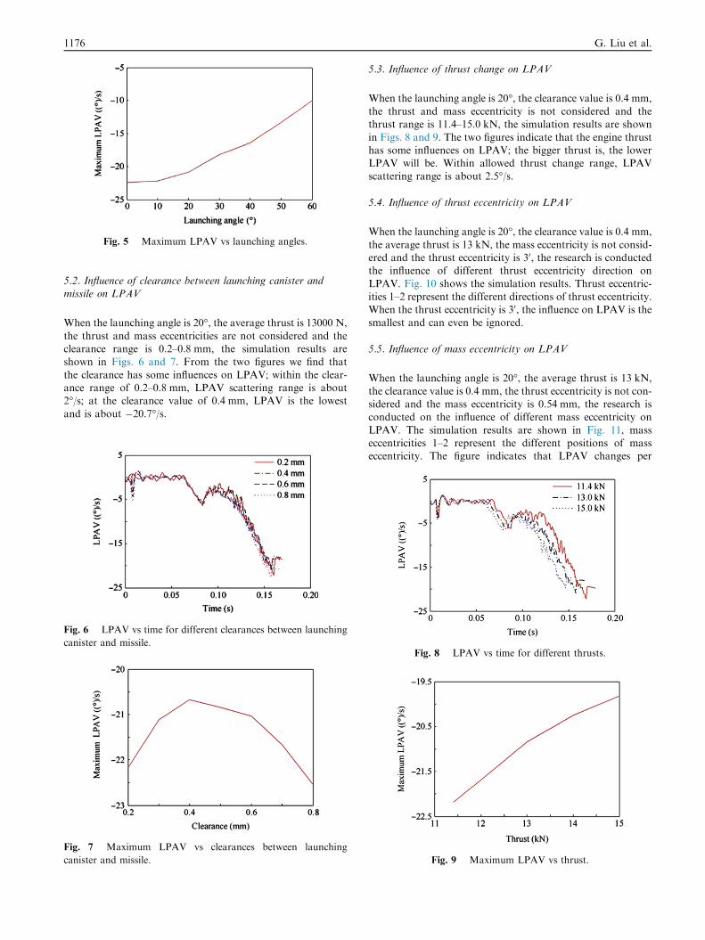
Fig. 5 Maximum LPAV vs launching angles.
1176 G. Liu et al.
5.2. Influence of clearance between launching canister andmissile on LPAV
When the launching angle is 20�, the average thrust is 13000 N,
the thrust and mass eccentricities are not considered and theclearance range is 0.2–0.8 mm, the simulation results areshown in Figs. 6 and 7. From the two figures we find that
the clearance has some influences on LPAV; within the clear-ance range of 0.2–0.8 mm, LPAV scattering range is about2�/s; at the clearance value of 0.4 mm, LPAV is the lowest
and is about �20.7�/s.
Fig. 6 LPAV vs time for different clearances between launching
canister and missile.
Fig. 7 Maximum LPAV vs clearances between launching
canister and missile.
5.3. Influence of thrust change on LPAV
When the launching angle is 20�, the clearance value is 0.4 mm,the thrust and mass eccentricity is not considered and thethrust range is 11.4–15.0 kN, the simulation results are shown
in Figs. 8 and 9. The two figures indicate that the engine thrusthas some influences on LPAV; the bigger thrust is, the lowerLPAV will be. Within allowed thrust change range, LPAVscattering range is about 2.5�/s.
5.4. Influence of thrust eccentricity on LPAV
When the launching angle is 20�, the clearance value is 0.4 mm,
the average thrust is 13 kN, the mass eccentricity is not consid-ered and the thrust eccentricity is 30, the research is conductedthe influence of different thrust eccentricity direction on
LPAV. Fig. 10 shows the simulation results. Thrust eccentric-ities 1–2 represent the different directions of thrust eccentricity.When the thrust eccentricity is 30, the influence on LPAV is the
smallest and can even be ignored.
5.5. Influence of mass eccentricity on LPAV
When the launching angle is 20�, the average thrust is 13 kN,
the clearance value is 0.4 mm, the thrust eccentricity is not con-sidered and the mass eccentricity is 0.54 mm, the research isconducted on the influence of different mass eccentricity on
LPAV. The simulation results are shown in Fig. 11, masseccentricities 1–2 represent the different positions of masseccentricity. The figure indicates that LPAV changes per
Fig. 8 LPAV vs time for different thrusts.
Fig. 9 Maximum LPAV vs thrust.
Fig. 11 LPAV vs time for different mass eccentricities.
Fig. 10 LPAV vs time for different thrust eccentricities.
Changing law of launching pitching angular velocity of rotating missile 1177
different mass eccentricity position. When the mass eccentric-
ity is 0.54 mm, LPAV scattering range is about 2.5�/s.
5.6. Influence of multifactor combination on LPAV
The influence of single factor on LPAV is analyzed in the pre-
vious paragraphs; however, all kinds of interference factors arevery complex. Therefore, it is quite necessary to have a combi-nation analysis on the factors.
According to the data offered by overall designer,multiple situations of these influence factors can be gained.Table 4 shows only 12 ones of these situations. According to
the defined parameter in Table 4, simulation results are shown
Fig. 12 LPAV vs time for multifactor combination.
Table 4 Multifactor combination.
Case Launching
angle (�)Clearance
(mm)
Thrust
(kN)
Mass
eccentricity
(mm)
Thrust
eccentricity
(0)
1 20 0.2 11.4 0.1 3
2 20 0.2 15.0 0.9 3
3 20 0.8 11.4 0.1 3
4 20 0.8 15.0 0.9 3
5 40 0.2 11.4 0.1 3
6 40 0.2 15.0 0.9 3
7 40 0.8 11.4 0.1 3
8 40 0.8 15.0 0.9 3
9 60 0.2 11.4 0.1 3
10 60 0.2 15.0 0.9 3
11 60 0.8 11.4 0.1 3
12 60 0.8 15.0 0.9 3
in Fig. 12, which indicate that LPAV scattering range is about
6�/s with the multi-factor combination; when the launchingangle is 20�, LPAV range is about (22 ± 3)�/s; when thelaunching angle is 40�, LPAV range is about (18 ± 3)�/s; whenthe launching angle is 20�, LPAV range is about (14 ± 3)�/s.
6. Changing law of LPAV
The virtual test simulation results reveal that among the influ-
ences of scattering factors on LPAV, the launching angle is themost significant one. The bigger launching angle is, the lowerLPAV will be; the influence of thrust eccentricity is tiny and
Fig. 13 Flight test validation.
1178 G. Liu et al.
can be ignored. With multifactor combination, at the same
launching angle, LPAV’s scattering range is about 6�/s, indi-cating a deviation of ±3�/s.
The virtual test data from the simulation can be fitted with
the linear regression method to obtain the changing law ofLPAV; its corrected and simplified mathematics model canbe expressed as26
_hp ¼ð0:15u� 25Þ � 3; 0o < u 6 20o
ð0:2u� 26Þ � 3; 20o < u 6 60o
�ð9Þ
where _hp is LPAV, and u is the launching angle. LPAV offeredby this corrected model enables better consistent between themultiple theoretic ballistic trajectory and flight test optical
measuring ballistic trajectory. So this model is quite applicable.Fig. 13 shows two flight trajectories of the closed-loop test.
7. Conclusions
(1) MFBD technology can truly simulate the contact non-linearity and material nonlinearity of complex objectsand be able to accurately and quickly calculate the con-
tact force between the flexible bodies and flexible bodyand rigid body, as well as non-linear deformation.
(2) Among the influences of scattering factors on LPAV, the
launching angle is the most one. The bigger the launchingangle is, the lower LPAV will be; the influence of thrusteccentricity is tiny and can be ignored. With combined
influence such as the clearance between missile and canis-ter, mass eccentricity and thrust change etc., at the samelaunching angle, LPAV’s scattering range is about 6�/s.
(3) Using the linear regression method, a simplified mathe-
matics model of corrected changing law of LPAV isobtained, which provides more accurate input forexterior trajectory optimization design and is verified by
physical flight tests.The research result has important engi-neering significance for tactical missile’s development.
Acknowledgements
The authors are grateful to the anonymous reviewers for theircritical and constructive review of the manuscript. This studywas supported by the Key Special Funds for National DefenseBasic Scientific Research of China (No. C0320110005).
References
1. Qian XF, Lin RX, Zhao YN. Missile flight mechanics. 1st
ed. Beijing: Beijing Institute of Technology Press; 2000. p.
136–43 [Chinese].
2. Bi SH, Li HB, Li LH, Fang YQ. Active control of initial
disturbance of rockets and missile. J B Inst Technol
2001;10(2):143–8.
3. Pamadi BN, Neirynck TA, Hotchko NJ, Tartabini PV, Scallion
WI, Murphy KJ, et al. Simulation and analysis of stage separation
of two-stage reusable launch vehicles; 2005. Report No.: AIAA-
2005-3247.
4. Liao SS, Wu C. Launching dynamics modeling of guided aircraft
missile and virtual prototype simulation. Trans B Inst Technol
2011;31(9):1013–7 [Chinese].
5. Cochran JE, Beaty JR. Simulation of the flight of a short
range air defense system rocket before radar acquisition.
Auburn (AL): Mechanical Engineering Department, School of
Engineering, Auburn University; 1977. Report No.:
ADA042036.
6. Cochran JE, Christensen DE. Launcher_rocket dynamics and
passive control; 1981. Report No.: AIAA-1981-1902.
7. Yao CR, Tang GL. Rocket and missile launching dynamics. 1st
ed. Beijing: Beijing Institute of Technology Press; 1996 [Chinese].
8. Bittle DA. TACAW/SFMTI launcher simulation. Alabama (CA):
Structures Directorate Research, Development, and Engineering
Center; 1997. Report No.: RD-ST-92-2.
9. Liu G, Lv JX. Dynamics simulation of rifle launching of certain
missile by means of virtual prototype technology. Tactical Missile
Technol 2005(5);61–5 [Chinese].
10. Cochran JE, No TS, Foster WA. Dynamics of flexible missile/
launcher systems; 1992. Report No.: AIAA-1992-4492-CP.
11. Cochran JE, Cheng YM, Bigelow S, Sandidge D, Benner J.
Multiple body missile launcher simulation; 1994. Report No.:
AIAA-1994-3451-CP.
12. Fu DB, Jiang Y. Dynamics simulation of guided missile launcher
based on coupled rigid and flexible model. J Syst Simul
2009;21(6):1789–91 [Chinese].
13. Gao XD, Bi SH, Chen Z. Flexible multi-body dynamics analysis
during missile launching based on improved Craig-Bampton
method. J Solid Rocket Technol 2011;34(5):559–63 [Chinese].
14. Baldesi G, Toso M. European Space Agency’s launcher multibody
dynamics simulator used for system and subsystem level analyses.
CEAS Space J 2012;3(1–2):27–48.
15. Jiao XJ, Zhang JW, Peng BB. RecurDyn multi-body system
optimization and simulation technology. Beijing: Tsinghua Pub-
lishing House; 2010 [Chinese].
16. Wijker J. Spacecraft structure. Heidelberg: Springer; 2008, p.
281–98.
17. Lee D, Hodges DH, Patil MJ. Multi-flexible-body dynamic
analysis of horizontal axis wind turbines. Wind Energ
2002;5(4):281–300.
18. Lee D, Hodges DH. Multi-flexible-body analysis for application to
wind turbine control design. Atlanta (GA): Georgia Tech
Research Corporation; 2004. Report No.: NREL/SR-500-35228.
19. Turtscher A, Fabbender F, Kelichhaus T. Simulation of dynamic
stresses including flexible contact s using MFBD technology. SAE;
2006. Report No.: 2006-01-2886.
20. Zaeh M, Siedl D. A new method for simulation of machining
performance by integrating finite element and multi-body simula-
tion for machine tools. Ann CIRP 2007;56(1):383–6.
21. Liu Y, Chen GD, Li JS, Xue YJ. Flexible multibody simulation
approach in the analysis of friction winder. Adv Mater Res
2010;97–101:2594–7.
22. Yao CR, Zhang B. The design of the launching device for rocket and
missile. 1st ed. Beijing: Beijing Institute of Technology Press;
1998 [Chinese].
Changing law of launching pitching angular velocity of rotating missile 1179
23. Li WL. A new method for structural model updating and joint
stiffness identification. Mech Syst Signal Process 2002;16(1):
155–67.
24. Mao KM, Li B, Wu J, Shao XY. Stiffness influential factors-based
dynamic modeling and its parameter identification method of fixed
joints in machine tools. Int J Mach Tools Manuf 2010;50(2):
156–64.
25. Wu DL, Ma JS, Li W. Verification validation and certification
based on virtual prototype simulation system. Comput Simul
2006;23(7):69–72 [Chinese].
26. Weisberg S. Applied linear regression. 3rd ed. New Jersey: John
Wiley & Sons, Inc.; 2005. p. 21–7.
Liu Guang is a Ph.D. candidate at Department of Mechanical and
Engineering Science, Fudan University, and a senior engineer at
Shanghai Electro-Mechanical Engineering Institute, China. His
research interests are mechanical system dynamics and aircraft design.
Xu Bin is a Ph.D. candidate at Department of Mechanical and Engi-
neering Science, Fudan University, and a senior engineer at Shanghai
Electro-Mechanical Engineering Institute, China. His research inter-
ests are nonlinear dynamics and aircraft design.
Jiao Xiaojuan is a Ph.D. candidate at Department of Mechanical and
Engineering Science, Fudan University, China. Her research interests
are in the areas of multi-body system dynamics.
Zheng Tiesheng is a professor and doctoral supervisor at Department
of Mechanical and Engineering Science, Fudan University, China. His
research fields are mechanical system dynamics, fluid-structure cou-
pling vibration, nonlinear dynamics, rotor dynamics and computa-
tional mechanics.