Embed Size (px)
Citation preview

ARIZONA DEPARTMENT OF TRANSPORTATION * MATERIALS GROUP
1221 NORTH 21ST AVENUE PHOENIX, ARIZONA 85009-3740 PHONE (602) 712 - 7231
CHANGE LETTER
MATERIALS TESTING MANUAL
CHANGE LETTER NO. 30
SUBJECT:
Title Page; Table of Contents; Series 100 Cover Sheet; Series 200 Cover Sheet; Series 400 Cover Sheet; Series 700 Cover Sheet; Arizona Test Methods 105e, 246b, 417d, 424c, 427a, 428, 732a, 743, and 744.
EFFECTIVE DATE:
April 19, 2013
SUMMARY:
NOTE: Unless otherwise specified, changes issued under this Change Letter are effective for projects with a bid opening date on or after April 19, 2013. Retain items removed from the Materials Testing Manual under this change letter for use as necessary on projects with a bid opening date prior to April 19, 2013.
1. TITLE PAGE - The Title Page has been revised to show the latest Change Letter
number and revision date. Please replace the existing Title Page with the attached. 2. TABLE OF CONTENTS - The Table of Contents has been revised to reflect the
changes made in this Change Letter. Please replace the existing Table of Contents with the attached.
3. The following items have been revised to reflect the changes made in this Change
Letter. Please replace the existing items with the attached.
Series 100 Cover Sheet - “SAMPLING”
Series 200 Cover Sheet - “SOILS AND AGGREGATES”
Series 400 Cover Sheet - “BITUMINOUS MIXTURES”
Series 700 Cover Sheet - “CHEMICAL AND SPECIALTY”
4. The following test methods have been revised. When necessary, the revisions include the use of the newly adopted format for Arizona Test Methods. Please replace the existing test methods with the attached.
MATERIALS TESTING MANUAL CHANGE LETTER NO. 30 April 19, 2013 Page 2
Arizona Test Method 105e - “SAMPLING SOILS AND AGGREGATES”
Revisions have been made to Table 1 in Subsection 1.4 [previously paragraph 1(d)].
A few editorial revisions have also been made to this test method.
Arizona Test Method 246b - “MOISTURE-DENSITY RELATIONSHIP USING TYPICAL MOISTURE-DENSITY CURVES (ONE POINT PROCTOR) ALTERNATE METHOD D”
In Subsection 5.10 [previously paragraph 5(j)], revisions have been made to the equation, and also the corresponding definition of the term “W”.
Table 1 has been revised to include column headings. A few editorial revisions have also been made to this test method.
Arizona Test Method 417d – “MAXIMUM THEORETICAL SPECIFIC GRAVITY AND DENSITY OF FIELD PRODUCED BITUMINOUS MIXTURES (RICE TEST)”
In the Note following Subsection 1.1 [previously paragraph 1(a)], the reference to “Arizona Test Method 416, Section 9” has been revised to read “Arizona Test Method 424”.
Revisions have been made to Subsection 5.4 [previously paragraph 5(d)]. Revisions have been made to Subsections 7.2 and 7.3 [previously
paragraphs 7(b) and 7(c)]. A new Note has also been inserted between Subsections 7.2 and 7.3.
A few editorial revisions have also been made to this test method, including a revision to the presentation of the equation in Subsection 6.1 [previously paragraph 6(a)].
Arizona Test Method 424c – “DETERMINATION OF AIR VOIDS IN COMPACTED BITUMINOUS MIXTURES”
An editorial revision (to delete repeated word “the”) has been made in Subsection 2.1.
Arizona Test Method 427a – “ASPHALT BINDER CONTENT OF ASPHALTIC CONCRETE MIXTURES BY THE IGNITION FURNACE METHOD”
Revisions have been made throughout this test method.

MATERIALS TESTING MANUAL CHANGE LETTER NO. 30 April 19, 2013 Page 3
Arizona Test Method 732a – “CALCIUM CARBONATE IN TOPSOIL (NEUTRALIZATION POTENTIAL OF TOPSOIL)”
Revisions have been made throughout this test method. 5. The following new test methods have been added to the Materials Testing Manual.
Arizona Test Method 428 – “ASPHALT BINDER CONTENT OF ASPHALTIC CONCRETE MIXTURES CONTAINING RECLAIMED ASPHALT PAVEMENT (RAP) BY THE IGNITION FURNACE METHOD”
Arizona Test Method 743 – “TITANIUM DIOXIDE IN PAINTS AND THERMOPLASTICS”
Arizona Test Method 744 – “ROCK SALT IN CRASH BARREL SAND”
Attachments


MATERIALS
TESTING MANUAL
SAMPLING AND TESTING PROCEDURES
PREPARED BY: ARIZONA DEPARTMENT OF TRANSPORTATION
INTERMODAL TRANSPORTATION DIVISION MATERIALS GROUP
REVISED TO CHANGE LETTER NO. 30 (April 19, 2013)


April 19, 2013 (5 Pages)
MATERIALS TESTING MANUAL
TABLE OF CONTENTS
Introduction (June 17, 2008) Glossary of Terms (July 15, 2005) SERIES 100 SAMPLING** ARIZ 103a Sampling Bituminous Materials ARIZ 104d Sampling Bituminous Mixtures ARIZ 105e Sampling Soils and Aggregates ARIZ 108 Sampling Hydrated Lime and Lime Products ARIZ 109 Sampling Metallic Materials ARIZ 110 Sampling Miscellaneous Materials ** The above Arizona Test Methods, and also commonly
used AASHTO procedures in this category, are shown on Series 100 Cover Sheet (April 19, 2013). SERIES 200 SOILS AND AGGREGATES** ARIZ 201c Sieving of Coarse and Fine Graded Soils and Aggregates ARIZ 205c Composite Grading ARIZ 210b Specific Gravity and Absorption of Coarse Aggregate ARIZ 211d Specific Gravity and Absorption of Fine Aggregate ARIZ 212e Percentage of Fractured Coarse Aggregate Particles ARIZ 220 Determination of Cement Content Required for Cement Treated Mixtures ARIZ 221 Moisture-Density Relations of Cement Treated Mixtures ARIZ 222b Rock Correction Procedure for Maximum Density Determination of Cement Treated Mixtures ARIZ 223 Field Density of Cement Treated Mixtures by Sand Cone Method or by Rubber Balloon Method ARIZ 225a Maximum Dry Density and Optimum Moisture of Soils by Proctor Method A ARIZ 226 Maximum Density and Optimum Moisture of Soils - Methods C and D ARIZ 227c Rock Correction Procedure for Maximum Dry Density and Optimum Moisture Content Determination

Materials Testing Manual Table of Contents April 19, 2013 Page 2 ARIZ 229a Calibration of Standard Sand and Sand Cone ARIZ 230a Field Density by the Sand Cone Method ARIZ 232b Moisture-Density Relationship Using Typical Moisture-Density Curves (One Point Proctor) Method A ARIZ 233c Flakiness Index of Coarse Aggregate ARIZ 235 Density and Moisture Content of Soil and Soil-Aggregate Mixtures by the Nuclear Method ARIZ 236c Determining pH and Minimum Resistivity of Soils and Aggregates ARIZ 237b Determining pH and Soluble Salts of Soils ARIZ 238a Percent Carbonates in Aggregate ARIZ 240a Sieve Analysis and Separation of Salvaged AC Pavement Particles for Recycled Asphaltic Concrete ARIZ 241a Compressive Strength of Molded Cement Treated Base or Soil-Cement Specimens ARIZ 242a Sand Equivalent Test for Mineral Aggregate for Asphaltic Concrete Friction Course ARIZ 244 Artificial Grading of Mineral Aggregate ARIZ 245 Maximum Dry Density and Optimum Moisture of Soils by Proctor Alternate Method D ARIZ 246b Moisture-Density Relationship using Typical Moisture-Density Curves (One Point Proctor) Alternate Method D ARIZ 247a Particle Shape and Texture of Fine Aggregate Using Uncompacted Void Content ARIZ 248 Alternate Procedures for Sieving of Coarse and Fine Graded Soils and Aggregates ARIZ 249 Remolded Ring Samples for Direct Shear, Swell, and Consolidation ARIZ 251a Combined Coarse and Fine Aggregate Specific Gravity and Absorption
** The above Arizona Test Methods, and also commonly used AASHTO procedures in this category, are shown on Series 200 Cover Sheet (April 19, 2013).
SERIES 300 CONCRETE** ARIZ 308a Method of Adjusting Concrete Mixes for Variations in Moisture Content ARIZ 309a Testing Impervious Materials and Compounds for Curing Concrete ARIZ 310a Measuring Texture Depth of Portland Cement Concrete with Metal Tine Finish ARIZ 311a Method of Test for Flow of Grout Mixtures (Flow Cone Method)

Materials Testing Manual Table of Contents April 19, 2013 Page 3 ARIZ 314b Compressive Strength of Cylindrical Concrete Specimens ARIZ 315 Precast Mortar Blocks Test ARIZ 317a Obtaining and Testing Drilled Cores and Sawed Beams of Concrete ARIZ 318 Estimating the Development of Concrete Strength by the Maturity Method
** The above Arizona Test Methods, and also commonly
used AASHTO and ASTM procedures in this category are show on Series 300 Cover Sheet (March 31, 2010).
SERIES 400 BITUMINOUS MIXTURES** ARIZ 406c Moisture Content of Bituminous Mixtures ARIZ 410e Compaction and Testing of Bituminous Mixtures Utilizing Four Inch Marshall Apparatus ARIZ 411a Determination of Bituminous Distributor Truck Transverse Spread Rate ARIZ 412b Density of Compacted Bituminous Mixtures by the Nuclear Method ARIZ 413 Extraction of Asphalt from Bituminous Mixtures by Soxhlet Extraction ARIZ 415c Bulk Specific Gravity and Bulk Density of Compacted Bituminous Mixtures ARIZ 416d Preparing and Splitting Field Samples of Bituminous Mixtures for Testing ARIZ 417d Maximum Theoretical Specific Gravity and Density of Field Produced Bituminous Mixtures (Rice Test) ARIZ 421 Bituminous Material Content of Asphaltic Concrete Mixtures by the Nuclear Method ARIZ 422 Compaction and Testing of Bituminous Mixtures Utilizing 152.4 mm (Six Inch) Marshall Apparatus ARIZ 424c Determination of Air Voids in Compacted Bituminous Mixtures ARIZ 427a Asphalt Binder Content of Asphaltic Concrete Mixtures by the Ignition Furnace Method ARIZ 428 Asphalt Binder Content of Asphaltic Concrete Mixtures Containing Reclaimed Asphalt Pavement (RAP) by the Ignition Furnace Method
** The above Arizona Test Methods, and also commonly used AASHTO procedures in this category, are show on Series 400 Cover Sheet (April 19, 2013).

Materials Testing Manual Table of Contents April 19, 2013 Page 4 SERIES 500 BITUMINOUS MATERIALS** ARIZ 502b Percentage of Uncoated Particles Using Asphalt Emulsions ARIZ 504 Vacuum Recovery of Asphalt Emulsion Residue ARIZ 505a Asphalt Rejuvenating Agent Residue Insoluble in Petroleum Ether ARIZ 509a Rapid Determination of Asphaltenes and Chemical Reactivity of Asphalts ARIZ 511 Recovery of Asphalt from Extraction Solution ARIZ 512a Residue by Evaporation ** The above Arizona Test Methods, and also commonly used AASHTO and ASTM procedures and specifications are
shown on Series 500 Cover Sheet (July 15, 2005). SERIES 600 CEMENT AND RELATED MATERIALS** ** Commonly used AASHTO and ASTM procedures in this category
are show on Series 600 Cover Sheet (July 15, 2005). SERIES 700 CHEMICAL AND SPECIALTY** ARIZ 702a Testing of Paint, Varnish, Lacquer, and Related Material ARIZ 714b Sampling and Sieving of Crumb Rubber ARIZ 719c Heating and Drying Materials in Microwave Oven ARIZ 725a Tensile Proof Dowel Test ARIZ 726a Reflectance, Dry Opacity, and Yellowness Index of Traffic Paint ARIZ 727a Chloride in Hardened Concrete ARIZ 729b Exchangeable Sodium in Topsoil ARIZ 732a Calcium Carbonate in Topsoil (Neutralization Potential of Topsoil) ARIZ 733a Sulfate in Soils ARIZ 734 Determination of Portland Cement Content in Cement Treated Base Material ARIZ 735a Testing of Thermoplastic Pavement Marking Material ARIZ 736a Chloride in Soils ARIZ 738 Chloride in Concrete Admixtures ARIZ 742 Mean Macrotexture Depth of Milled Pavement ARIZ 743 Titanium Dioxide in Paints and Thermoplastics ARIZ 744 Rock Salt in Crash Barrel Sand ** The above Arizona Test Methods, and also commonly used AASHTO and ASTM procedures in this category are
show on Series 700 Cover Sheet (April 19, 2013).

Materials Testing Manual Table of Contents April 19, 2013 Page 5 SERIES 800 DESIGN** ARIZ 801a Evaluation of Profiles ARIZ 802g Effect of Water on Strength of Compacted Bituminous Mixtures (Immersion Compression Test) ARIZ 805b Centrifuge Kerosene Equivalent of Aggregate, Including K-Factor ARIZ 806e Maximum Theoretical Specific Gravity of Laboratory Prepared Bituminous Mixtures (Rice Test) ARIZ 807 Design of Slurry Seal ARIZ 814a Design of Asphaltic Concrete Friction Course ARIZ 815d Marshall Mix Design Method for Asphaltic Concrete ARIZ 819a Design of Exposed Aggregate Seal Coats ARIZ 822 Determination of Additive or Asphalt Blend Required for Modification of Asphalt Viscosity ARIZ 825a Method of Test for Determining the Quantity of Asphalt Rejuvenating Agent Required for an Asphaltic Pavement ARIZ 829a Evaluation of Pavement Smoothness ARIZ 832a Marshall Mix Design Method for Asphaltic Concrete (Asphalt-Rubber) [AR-AC] ARIZ 833 Marshall Mix Design Method for Asphaltic Concrete with Reclaimed Asphalt Pavement (RAP) ** The above Arizona Test Methods are also shown on Series 800 Cover Sheet (February 22, 2013). SERIES 900 MATERIALS QUALITY ASSURANCE PROGRAM (January 7, 2011) Appendix A - BLANK
Appendix B - BLANK Appendix C - Sampling Guide Schedule SERIES 1000 CERTIFICATES (July 15, 2005) APPENDIX APPENDIX A1 Rounding Procedure (July 15, 2005) APPENDIX A2 Metric Guide (July 15, 2005) APPENDIX A3 Equipment Calibration and Verification (September 28, 2012)


April 19, 2013 (1 Page)
SERIES 100
SAMPLING
The following methods shall be performed in accordance with the respective designation: ARIZONA TEST METHODS: TITLE DESIGNATION Sampling Bituminous Materials…………………………………. ARIZ 103a Sampling Bituminous Mixtures………………………………….. ARIZ 104d Sampling Soils and Aggregates………………………………... ARIZ 105e Sampling Hydrated Lime and Lime Products…………………. ARIZ 108 Sampling Metallic Materials…………..…………………………. ARIZ 109 Sampling Miscellaneous Materials……………………………… ARIZ 110 Note: Sampling of crumb rubber is performed in accordance with Arizona Test Method 714.
AASHTO TEST METHODS: TITLE DESIGNATION Sampling and Testing Brick ……………………………………... T 32 Sampling and Amount of Testing of Hydraulic Cement .....….. T 127 Sampling Freshly Mixed Concrete .....................................….. T 141 Reducing Samples of Aggregate to Testing Size……………… T 248
NOTE: It shall be assured that the appropriate methods as given in the project requirements are being adhered to. NOTE: Refer to Series 900, “Materials Quality Assurance Program”, of the Materials Testing Manual for current guidelines on sampling of materials for acceptance, independent assurance, and correlation testing.


April 19, 2013 (4 Pages)
SERIES 200
SOILS AND AGGREGATES
The following test methods and standards shall be performed in accordance with the respective designation: ARIZONA TEST METHODS: TITLE DESIGNATION
Sieving of Coarse and Fine Graded Soils and Aggregates ………….……………………………..……... ARIZ 201c Composite Grading ………….………………………………….… ARIZ 205c Specific Gravity and Absorption of Coarse Aggregate ….….… ARIZ 210b Specific Gravity and Absorption of Fine Aggregate …….……... ARIZ 211d Percentage of Fractured Coarse Aggregate Particles ….….…. ARIZ 212e Determination of Cement Content Required for Cement Treated Mixtures …….………………………..…. ARIZ 220
Moisture-Density Relations of Cement Treated
Mixtures ……………….…………………………………..……. ARIZ 221 Rock Correction Procedure for Maximum Density Determination of Cement Treated Mixtures ……..…….....… ARIZ 222b Field Density of Cement Treated Mixtures by Sand Cone Method or by Rubber Balloon Method ....................... ARIZ 223 Maximum Dry Density and Optimum Moisture of Soils by Proctor Method A ………….………………..……. ARIZ 225a Maximum Density and Optimum Moisture of Soils – Methods C and D ………………..………….………… ARIZ 226 Rock Correction Procedure for Maximum Dry Density and Optimum Moisture Content Determination ….……..….. ARIZ 227c

SERIES 200 SOILS AND AGGREGATES April 19, 2013 Page 2 ARIZONA TEST METHODS: (continued)
TITLE DESIGNATION
Calibration of Standard Sand and Sand Cone …….……...…… ARIZ 229a
Field Density by the Sand Cone Method ………….…..…….….. ARIZ 230a
Moisture-Density Relationship Using Typical Moisture-Density Curves (One Point Proctor) Method A …….……….………………………..………..…….. ARIZ 232b Flakiness Index of Coarse Aggregate ……….………..……….... ARIZ 233c Density and Moisture Content of Soil and Soil-Aggregate Mixtures by the Nuclear Method ……..….… ARIZ 235 Determining pH and Minimum Resistivity of Soils and
Aggregates ……………….……………………....................... ARIZ 236c Determining pH and Soluble Salts of Soils ……….…..…..….… ARIZ 237b
Percent Carbonates in Aggregate ……………………...……...... ARIZ 238a
Sieve Analysis and Separation of Salvaged AC Pavement
Particles for Recycled Asphaltic Concrete …………….……. ARIZ 240a Compressive Strength of Molded Cement Treated Base or Soil-Cement Specimens ……….......…….. ARIZ 241a Sand Equivalent Test for Mineral Aggregate for Asphaltic Concrete Friction Course ……………………… ARIZ 242a
Artificial Grading of Mineral Aggregate ………………......…….. ARIZ 244
Maximum Dry Density and Optimum Moisture of Soils by Proctor Alternate Method D ………...…………… ARIZ 245 Moisture-Density Relationship using Typical Moisture-Density Curves (One Point Proctor) Alternate Method D ……………………………………………. ARIZ 246b Particle Shape and Texture of Fine Aggregate Using
Uncompacted Void Content …………...…………..……….... ARIZ 247a

SERIES 200 SOILS AND AGGREGATES April 19, 2013 Page 3
ARIZONA TEST METHODS: (continued)
TITLE DESIGNATION
Alternate Procedures for Sieving of Coarse and Fine Graded Soils and Aggregates ……………………………...…….……. ARIZ 248
Remolded Ring Samples for Direct Shear, Swell, and
Consolidation ………………………………….…………..…… ARIZ 249 Combined Coarse and Fine Aggregate Specific Gravity and
Absorption …………………………………………………...…. ARIZ 251a AASHTO STANDARDS: TITLE DESIGNATION Dry Preparation of Disturbed Soil and Soil-Aggregate Samples for Test ……….……………………. R 58 Bulk Density (“Unit Weight”) and Voids in Aggregate ….………. T 19 Determining the Liquid Limit of Soils ……….……………………. T 89 Determining the Plastic Limit and
Plasticity Index of Soils ………….…………………………...... T 90 Resistance to Degradation of Small-Size
Coarse Aggregate by Abrasion and Impact in the Los Angeles Machine …………….…………………….. T 96
Soundness of Aggregate by Use of
Sodium Sulfate or Magnesium Sulfate ……….……………… T 104 Wetting-and-Drying Test of Compacted Soil-Cement Mixtures …………………….……………………. T 135 Freezing-and-Thawing Tests of Compacted Soil-Cement Mixtures ……………….…………………………. T 136 Plastic Fines in Graded Aggregates and Soils by Use of the Sand Equivalent Test ……….………….……... T 176

SERIES 200 SOILS AND AGGREGATES April 19, 2013 Page 4 AASHTO STANDARDS: (continued) TITLE DESIGNATION Resistance R-Value and Expansion Pressure of Compacted Soils ……………………………..… T 190 Determination of Moisture in Soils by Means of a Calcium Carbide Gas Pressure Moisture Tester ……………………………………. T 217 Determination of Strength of Soil-Lime Mixtures ……………………….………………..…. T 220 Reducing Field Samples of Aggregates to Testing Size …………………………………………..…… T 248 Total Evaporable Moisture Content of Aggregate by Drying ……………………………………….... T 255 Laboratory Determination of Moisture Content of Soils …………………………………… T 265 NOTE: It shall be assured that the appropriate test methods and standards as given in the project requirements are being adhered to.
April 19, 2013 (2 Pages)
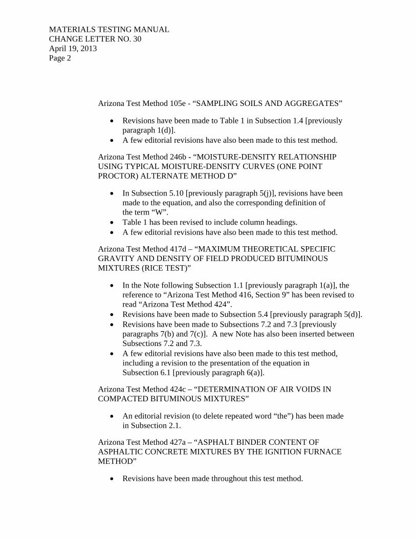
SERIES 400
BITUMINOUS MIXTURES
The following test methods shall be performed in accordance with the respective designation: ARIZONA TEST METHODS:
TITLE DESIGNATION
Moisture Content of Bituminous Mixtures………………………. ARIZ 406c
Compaction and Testing of Bituminous Mixtures Utilizing Four Inch Marshall Apparatus……………….………….……. ARIZ 410e Determination of Bituminous Distributor Truck Transverse Spread Rate……………………………………… ARIZ 411a
Density of Compacted Bituminous Mixtures by the Nuclear Method……………………………………………. ARIZ 412b Extraction of Asphalt from Bituminous Mixtures by Soxhlet Extraction………………………….…….……......….. ARIZ 413 Bulk Specific Gravity and Bulk Density of Compacted
Bituminous Mixtures…………………………………………... ARIZ 415c Preparing and Splitting Field Samples of Bituminous Mixtures for Testing………………………..………………..… ARIZ 416d Maximum Theoretical Specific Gravity and Density of Field Produced Bituminous Mixtures (Rice Test)…………….…... ARIZ 417d Bituminous Material Content of Asphaltic Concrete Mixtures by the Nuclear Method………………….………..… ARIZ 421 Compaction and Testing of Bituminous Mixtures Utilizing
152.4 mm (Six Inch) Marshall Apparatus…………………… ARIZ 422

SERIES 400 BITUMINOUS MIXTURES April 19, 2013 Page 2
ARIZONA TEST METHODS: (continued)
TITLE DESIGNATION
Determination of Air Voids in Compacted Bituminous Mixtures…………………………………………...……..….….. ARIZ 424c
Asphalt Binder Content of Asphaltic Concrete Mixtures by the Ignition Furnace Method………..………….…………. ARIZ 427a Asphalt Binder Content of Asphaltic Concrete Mixtures Containing Reclaimed Asphalt Pavement (RAP) by the Ignition Furnace Method…….…………..……. ARIZ 428
AASHTO TEST METHODS:
TITLE DESIGNATION
Quantitative Extraction of Bitumen from Bituminous Paving Mixtures………………………………………………... T 164 Preparing and Determining the Density of Hot-Mix
Asphalt (HMA) Specimens by Means of the Superpave Gyratory Compactor...………….………..….…... T 312
NOTE: It shall be assured that the appropriate test methods as given in the project requirements are being adhered to.

April 19, 2013 (2 Pages)
SERIES 700
CHEMICAL AND SPECIALTY
The following test methods shall be performed in accordance with the respective designation: ARIZONA TEST METHODS: TITLE DESIGNATION
Testing of Paint, Varnish, Lacquer, and Related Material………………………………………….... ARIZ 702a
Sampling and Sieving of Crumb Rubber………………….... ARIZ 714b Heating and Drying Materials in Microwave Oven…………. ARIZ 719c Tensile Proof Dowel Test……………………………………… ARIZ 725a Reflectance, Dry Opacity, and Yellowness Index of Traffic Paint…………………………………….... ARIZ 726a Chloride in Hardened Concrete…………………………….… ARIZ 727a
Exchangeable Sodium in Topsoil…………………………….. ARIZ 729b Calcium Carbonate in Topsoil (Neutralization Potential of Topsoil).…………………………….……..….. ARIZ 732a Sulfate in Soils……………………………………………..……. ARIZ 733a Determination of Portland Cement Content in Cement Treated Base Material……………………………. ARIZ 734
Testing of Thermoplastic Pavement Marking Material……… ARIZ 735a Chloride in Soils…………………………………………...…….. ARIZ 736a Chloride in Concrete Admixtures………………………………. ARIZ 738 Mean Macrotexture Depth of Milled Pavement………………. ARIZ 742

SERIES 700 CHEMICAL AND SPECIALTY April 19, 2013 Page 2
ARIZONA TEST METHODS: (continued) TITLE DESIGNATION
Titanium Dioxide in Paints and Thermoplastics…………….. ARIZ 743 Rock Salt in Crash Barrel Sand….…………………………… ARIZ 744
AASHTO & ASTM TEST METHODS:
DESIGNATION
TITLE AASHTO ASTM Quality of Water To Be Used in Concrete ................................ T 26 Sampling and Testing Brick ..................................................... T 32 Preformed Expansion Joint Filler for Concrete Construction ........................................................
T 42
Mass [Weight] of Coating on Iron or Steel Articles with Zinc or Zinc-Alloy Coatings ..........................................
T 65
Mechanical Testing of Steel Products ...................................... T 244 Roundness of Glass Spheres .................................................. D 1155 Rubber Property - Durometer Hardness .................................. D 2240 Water Permeability of Geotextiles by Permittivity .................... D 4491 Rockwell Hardness of Metallic Materials .................................. E 18 NOTE: It shall be assured that the appropriate test methods as given in the project requirements are being adhered to.

ARIZ 105e April 19, 2013 (7 Pages)
SAMPLING SOILS AND AGGREGATES
(An Arizona Method)
1. SCOPE 1.1 This method describes the methods which are to be used when sampling
soils and aggregates. 1.2 Sampling is equally as important as the testing, and the individual doing
the sampling shall use every precaution to obtain samples that will be representative of the materials being sampled.
1.3 This test method may involve hazardous material, operations, or
equipment. This test method does not purport to address all of the safety concerns associated with its use. It is the responsibility of the user to consult and establish appropriate safety and health practices and determine the applicability of any regulatory limitations prior to use.
1.4 Table 1 shall be used to determine minimum sample weights based on the
size of aggregate. The amount of material required may be greater depending on the tests that are to be performed on the material.
Table 1
Minimum Sample Sizes Sample Mass Nominal Maximum
Aggregate Size * kg lbs Fine Aggregate
#8 10 22 #4 10 22
Coarse Aggregate 3/8” 10 22 1/2” 15 35 3/4” 25 55 1” 50 110
1-1/2” 75 165 2” 100 220
2-1/2” 125 275 3” 150 330
* The smallest sieve opening through which the entire amount of material, by specification, is permitted to pass.

ARIZ 105e April 19, 2013 Page 2 2. SAMPLING FROM STOCKPILES 2.1 In sampling materials from stockpiles it is difficult to ensure unbiased
samples, due to the segregation which often occurs when the material is stockpiled with coarser particles rolling to the outside base of the pile. If power equipment is available then it would be advantageous to enlist the use of that equipment to develop a separate, small sampling pile composed of materials drawn from various levels and locations in the main stockpile. Once a small sampling pile has been established then a sample shall be taken from that pile by taking several increments and combining.
2.2 The stockpile may also be sampled by placing a wood or metal shield
upslope from the point of sampling to prevent loose aggregate from sliding down into the sampling area. Remove approximately 3 to 6 inches of material from the sampling area. Utilizing a square point shovel, take a sample near the top, at the middle and near the bottom of the stockpile. The sample taken at each location shall be one shovelful of material. Repeat this operation at the sampling locations as shown in Figure 1, and combine all samples taken from the stockpile.
3. SAMPLING FROM BINS 3.1 A sample shall be taken by passing a sampling device through the entire
cross-section of the flow of material as it is being discharged (see Figures 2 and 3). Sufficient material shall be allowed to pass at the beginning of discharge to ensure uniformity of material before the sample is taken. Repeat sampling procedure as necessary until the desired amount of material from each bin is obtained. Material from each bin shall be properly identified.
4. SAMPLING FROM A CONVEYOR BELT 4.1 Sampling from a conveyor belt may be performed either while the
conveyor belt is running (by using a sampling device which diverts or intercepts the flow of material) or by taking a sample while the conveyor belt is stopped. The stopped belt method is also used when approving a sampling device used for sampling while the belt is running.
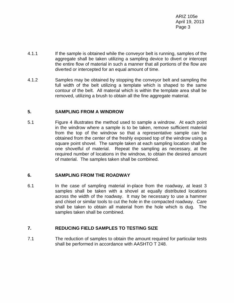
ARIZ 105e April 19, 2013 Page 3 4.1.1 If the sample is obtained while the conveyor belt is running, samples of the
aggregate shall be taken utilizing a sampling device to divert or intercept the entire flow of material in such a manner that all portions of the flow are diverted or intercepted for an equal amount of time.
4.1.2 Samples may be obtained by stopping the conveyor belt and sampling the
full width of the belt utilizing a template which is shaped to the same contour of the belt. All material which is within the template area shall be removed, utilizing a brush to obtain all the fine aggregate material.
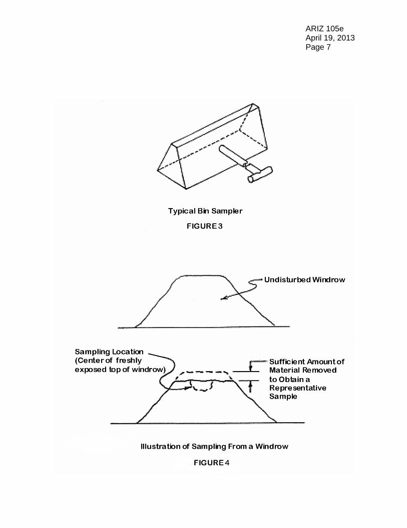
5. SAMPLING FROM A WINDROW 5.1 Figure 4 illustrates the method used to sample a windrow. At each point
in the windrow where a sample is to be taken, remove sufficient material from the top of the windrow so that a representative sample can be obtained from the center of the freshly exposed top of the windrow using a square point shovel. The sample taken at each sampling location shall be one shovelful of material. Repeat the sampling as necessary, at the required number of locations in the windrow, to obtain the desired amount of material. The samples taken shall be combined.
6. SAMPLING FROM THE ROADWAY 6.1 In the case of sampling material in-place from the roadway, at least 3
samples shall be taken with a shovel at equally distributed locations across the width of the roadway. It may be necessary to use a hammer and chisel or similar tools to cut the hole in the compacted roadway. Care shall be taken to obtain all material from the hole which is dug. The samples taken shall be combined.
7. REDUCING FIELD SAMPLES TO TESTING SIZE 7.1 The reduction of samples to obtain the amount required for particular tests
shall be performed in accordance with AASHTO T 248.

ARIZ 105e April 19, 2013 Page 4 8. SAMPLE IDENTIFICATION 8.1 Each sample shall be identified by an accompanying ticket. Sample
tickets shall be filled out as required to provide necessary information. The remarks area of the sample ticket should be used as necessary to provide additional information.
8.2 The source of the sample shall be the “original source” of the material, as
indicated on the sample ticket. 8.3 An example of a completed sample ticket used by ADOT for construction
projects is given below.
8.4 The sample ticket consists of three copies. The center copy in kept by the
person submitting the sample, the original copy is included inside the sample container, and the third copy is attached to the sample container. When filling out sample tickets, make certain information is clear and easily read on all three copies.

ARIZ 105e April 19, 2013 Page 5

ARIZ 105e April 19, 2013 Page 6
ARIZ 105e April 19, 2013 Page 7


ARIZ 246b April 19, 2013 (12 Pages)
MOISTURE - DENSITY RELATIONSHIP USING TYPICAL MOISTURE - DENSITY CURVES
(ONE POINT PROCTOR) ALTERNATE METHOD D
(An Arizona Method)
1. SCOPE 1.1 This method of test is for the determination of the optimum moisture
content and maximum dry density of a soil or soil-aggregate mixture utilizing one moisture-density determination on the portion of the sample passing the 3/4 inch sieve.
1.2 The one-point proctor is used with the typical moisture-density curves,
shown on the back of the One Point Proctor Density Test Card (Figures 1 and 2); or by utilizing a family of moisture-density curves developed for the immediate local conditions.
1.3 This method is not to be used for volcanic cinders or light porous material
on which the specific gravity cannot be determined with consistency or when the absorption of the coarse aggregate is greater than 4.0%.
1.4 This method may be used to determine if an existing proctor maximum
density determination is valid for the soil being tested. If the existing proctor maximum density determination is not valid, a full proctor according to Arizona Test Method 245 should normally be run to determine the maximum density required for that soil type.
1.5 An example is provided in Section 7, and Figures 3 and 4, for the
calculations and determinations referenced herein. 1.6 This test method may involve hazardous materials, operations, and
equipment. This test method does not purport to address all of the safety concerns associated with its use. It is the responsibility of who ever uses this test method to consult and establish appropriate safety and health practices and determine the applicability of regulatory limitations prior to use.

ARIZ 246b April 19, 2013 Page 2 2. APPARATUS 2.1 The apparatus shall consist of the following: 2.1.1 The apparatus utilized for this test method shall conform to the apparatus
requirements of Arizona Test Method 245. 2.1.1.1 Instead of the 230 9 F oven, a hot plate or stove capable of maintaining
a temperature of approximately 230 F may be used. A Speedy Moisture Tester with a conversion table or calibration curve may also be used for moisture determinations made in the field. Finally, a microwave oven may be used in accordance with Arizona Test Method 719.
2.1.1.2 Instead of the scale or balance capable of measuring the weight to be
determined to at least one gram, a scale capable of measuring the weight to at least 0.01 pound may be utilized.
3. CALIBRATION OF MOLD 3.1 Molds shall be calibrated in accordance with APPENDIX A of Arizona Test
Method 225. 4. SAMPLE 4.1 A representative sample of passing 3/4 inch material weighing
approximately 5000 grams shall be obtained for each one-point proctor. 5. PROCEDURE 5.1 If the Speedy Moisture Tester is not to be used in making the moisture
content determination, proceed to Subsection 5.4. 5.2 For testing performed in the field, the Speedy Moisture Tester (AASHTO
T 217) may be used to make the moisture content determination. The approximate 5000 gram sample of pass 3/4 inch material is sieved over a No. 4 sieve. Calculate the percent of coarse aggregate or rock particles retained on the No. 4 sieve by the following:
100 x WT
WR4 PR4

ARIZ 246b April 19, 2013 Page 3 Where: PR4 = Percentage of coarse aggregate or rock particles retained on the No. 4 sieve. WR4 = Weight of coarse aggregate or rock particles retained on the No. 4 sieve. WT = Total Weight of material sieved. 5.3 Recombine and thoroughly blend the plus No. 4 material with the passing
No. 4 material. 5.4 The approximate 5000 gram sample of passing 3/4 inch material shall be
thoroughly mixed with sufficient water to bring the sample to slightly less than its optimum moisture content.
5.5 Form a specimen by compacting the prepared soil in the six inch mold
(with extension collar attached) in three equal layers to give a total compacted depth of about 5 inches. Compact each layer with 56 uniformly distributed blows from the rammer, dropping free from a height of 12 inches. While each layer is being compacted, the remainder of material shall be in a pan covered by a damp cloth. During compaction, the mold shall rest firmly on a dense, uniform, rigid, and stable foundation.
Note: Each of the following has been found to be a satisfactory
base on which to rest the mold during compaction of the soil: a block of concrete, weighing not less than 200 lbs., supported by a stable foundation; a sound concrete floor; and for field application, such surfaces as found in concrete box culverts, bridges, and pavements.
5.6 When compacting granular, free-draining materials, at moisture contents
which are at or above optimum, the mold shall be prepared by first sealing the bottom of the mold with waterproofing grease. All excess grease shall be wiped from the mold and base plate.
5.7 Following compaction, carefully remove the extension collar. It may be
necessary to use a follower to retain the soil in the mold while removing the collar to prevent damage or disturbance of the soil below the top of the mold. Carefully trim the compacted soil even with the top of the mold by means of the straightedge. If any voids are created during trimming, these shall be filled with fine material and smoothed off. Determine the weight of compacted specimen and mold. Determine the wet density, “WD”, of the compacted soil by the following:

ARIZ 246b April 19, 2013 Page 4
*)(grams/lb. 453.6 x MV
M2 - M1 WD
Where: WD = Wet density of compacted soil, Ib./cu. ft. M1 = Weight of compacted specimen and mold, grams or lbs. M2 = Weight of the mold, grams or lbs. VM = Volume of the mold, cu. ft. (See Section 3 of this procedure).
* If the weights of the compacted specimen and mold, M1, and the empty mold, M2, are measured in pounds, eliminate “453.6 (grams/lb.)” from the denominator of the above equation.
5.8 The moisture content of the sample is determined either by drying (See
Subsection 5.9); or, when testing is performed in the field, the Speedy Moisture Tester may be used (See Subsection 5.10).
5.9 When the percent moisture is determined by drying, remove the material
from the mold and slice vertically through the center. Take a representative minimum 600 gram sample from the full length and width of one of the cut faces. Record the weight of wet soil to the nearest 0.1 gram as “WW”. Dry the sample to constant weight at approximately 230 F and record weight of dry soil to the nearest 0.1 gram as “DW”. The percent moisture shall be recorded to the nearest 0.1 percent. The equation below is used when the percent moisture is determined by drying the sample.
100 x DW
DW - WW Moisture %
Where: WW = Wet weight of moisture sample. DW = Dry weight of moisture sample. 5.10 For testing in the field, the percent moisture may be determined using the
Speedy Moisture Tester. Remove the material from the mold and slice vertically through the center. Obtain a minimum of 600 grams of material from the full length and width of one of the cut faces. This material is screened over a No. 4 sieve as rapidly as possible to avoid drying of the sample. A representative sample of the pass No. 4 material shall be utilized and tested in accordance with the instructional manual for that apparatus. The percent moisture of the pass No. 4 material determined

ARIZ 246b April 19, 2013 Page 5
by the Speedy Moisture Tester is recorded to the nearest 0.1 percent as “W”. The moisture content of the pass 3/4 inch material is determined and recorded as “TW” to the nearest 0.1 percent by the following:
100
PR4 PR4) - (100 W TW
Where: TW = % moisture in pass 3/4 material. W = % moisture in pass No. 4 material (determined by Speedy). PR4 = % rock retained on the No. 4 sieve (determined in Subsection 5.2). 6. MAXIMUM DENSITY DETERMINATION 6.1 The point representing the wet density and moisture content (dry basis) is
then plotted on the Typical Moisture-Density Curves (Figure 2) and the maximum wet density and optimum moisture content determined. When this plotted point falls between two moisture-density curves, a minor interpolation is necessary. The maximum dry density in lb/cu. ft. and the corresponding percent optimum moisture is then read directly or interpolated from the chart. The family of typical moisture-density curves provided should be periodically verified for the local conditions. If it is ascertained that the family of curves provided by Figure 2 is of questionable reliability for given local conditions, then an independent family of curves should be established and used.
6.2 The plotted point for wet density and moisture content should be on the
dry side of the curve at or near optimum, as it is difficult to interpolate between curves for friable soils when on the wet side of the peak.
6.3 If the plotted point representing the wet density and moisture content of
the compacted material is on the right of the peak, the test should be repeated using a lower moisture content. An exception to this rule must be made for those soils having high clay contents and relatively flat curves. These soils cannot readily be dried to optimum in the field due to the creation of a cloddy condition which will cause voids in the proctor. Proctors for these materials should be made as near to optimum as possible.

ARIZ 246b April 19, 2013 Page 6 7. EXAMPLE 7.1 An illustration of determining the maximum dry density and optimum
moisture content is described below, and shown in Figures 3 and 4: For: Wet Density = 122.5 lb./cu. ft. Moisture Content = 18.7%
By plotting this point on the Typical Moisture-Density Curves and interpolating to the peak, it shows a point which is approximately 20 percent of the distance from Curve P to Curve Q. From the chart, the dry density for Curve P is 104.7 lb./cu. ft. @ 19.2% moisture and the dry density for Curve Q is 102.4 lb./cu. ft. @ 20.3% moisture.
By interpolation: Density: 104.7 - 102.4 = 2.3 0.20 X 2.3 = 0.5 lb./cu. ft. difference Moisture: 20.3- 19.2 = 1.1 0.20 X 1.1 = 0.2% difference Therefore: Maximum dry density = 104.7 - 0.5 = 104.2 lb./cu. ft. Optimum Moisture = 19.2 + 0.2 = 19.4% 7.1.1 As an alternate to performing the interpolation procedure above, TABLE 1
can be used to determine the maximum dry density and optimum moisture content when the plotted point falls between two moisture-density curves.
ARIZ 246b April 19, 2013 Page 7
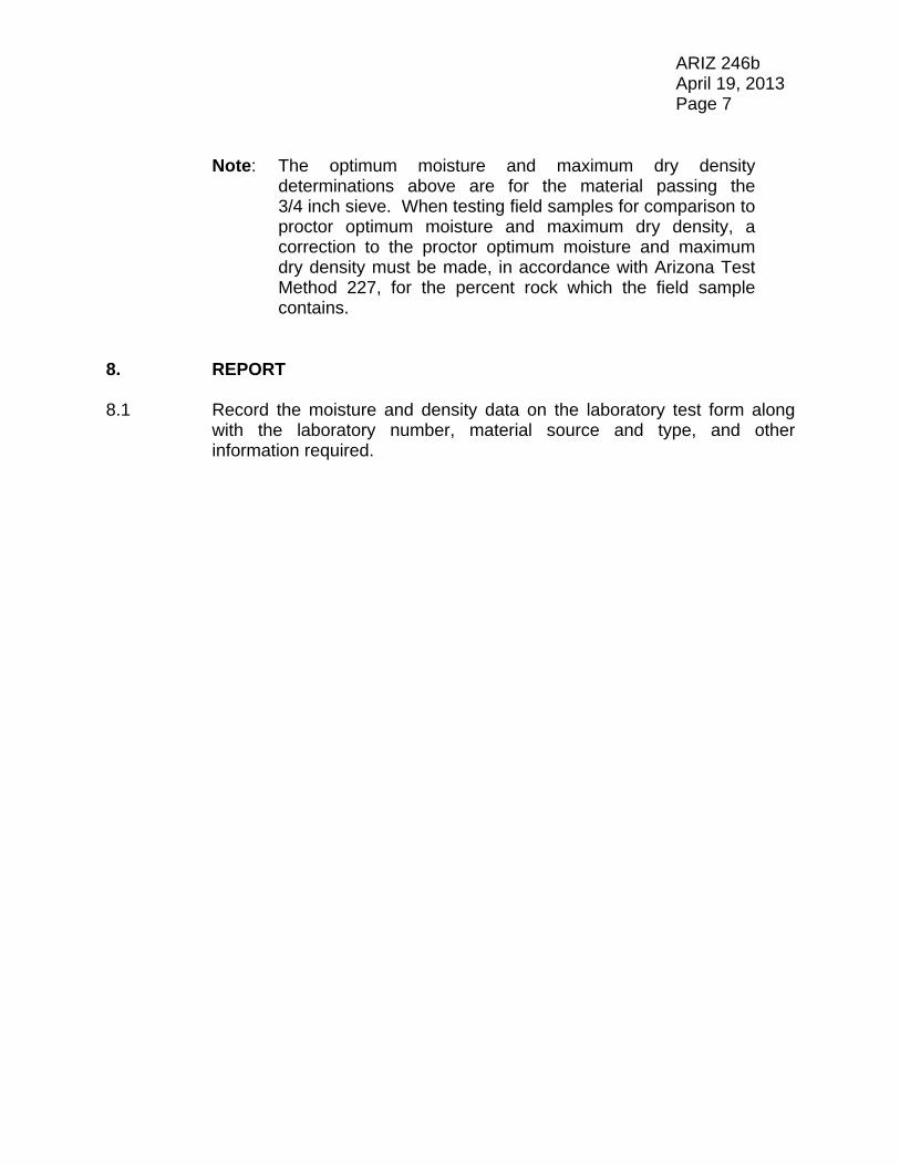
Note: The optimum moisture and maximum dry density determinations above are for the material passing the 3/4 inch sieve. When testing field samples for comparison to proctor optimum moisture and maximum dry density, a correction to the proctor optimum moisture and maximum dry density must be made, in accordance with Arizona Test Method 227, for the percent rock which the field sample contains.
8. REPORT 8.1 Record the moisture and density data on the laboratory test form along
with the laboratory number, material source and type, and other information required.

ARIZ 246b April 19, 2013 Page 8
TABLE 1

ARIZ 246b April 19, 2013 Page 9
ONE POINT PROCTOR DENSITY
Lab. No: Org No.: Date:
Project No. TRACS No.
Original Source: Type of Material:
Coarse Agg. % Absorp.: Coarse Agg. Bulk O.D. Sp. Gr.:
Proctor Method Used: Method A Alternate Method D
Test Operator: Date:
Supervisor: Date:
Wet Density Determination Volume of Mold = VM = cu. ft.
Weight of Mold = M2 = grams pounds
Weight of Sample and Mold = M1 = grams pounds M1 – M2
Wet Density = WD = = lb./cu.ft. VM x 453.6 (grams/lb.)*
*If M1 and M2 are in pounds, eliminate “453.6 (grams/lb.)” from denominator in above equation.
Percent Moisture Determination For either Method A or Alternate Method D, when sample is oven dried:
Wet Weight of Moisture Sample = WW = grams
Dry Weight of Moisture Sample = DW = grams
WW - DW % Moisture = x 100 = %
DW
For Method A, when Speedie Moisture Tester is used: % Moisture = % For Alternate Method D, when Speedie Moisture Tester is used:
WT = WR4 = PR4 = 1004 WTWR = %
% Moisture in Pass No. 4 material from Speedie = W = %
[W(100 — PR4)] + PR4 Total % Moisture = TW = = %
100
From Typical Moisture-Density Curves: Maximum Dry Density = MD = lb./cu. ft. Percent Optimum Moisture = OM = % REMARKS:
FIGURE 1

AR
IZ 246b
April 19, 2013
Page 10
FIG
UR
E 2

ARIZ 246b April 19, 2013 Page 11
ONE POINT PROCTOR DENSITY
Lab. No: Org No.: Date:
Project No. TRACS No.
Original Source: Type of Material:
Coarse Agg. % Absorp.: Coarse Agg. Bulk O.D. Sp. Gr.:
Proctor Method Used: Method A Alternate Method D X
Test Operator: Date:
Supervisor: Date:
Wet Density Determination Volume of Mold = VM = 0.0758 cu. ft.
Weight of Mold = M2 = 6608 grams pounds
Weight of Sample and Mold = M1 = 10820 grams pounds M1 – M2
Wet Density = WD = = 122.5 lb./cu.ft. VM x 453.6 (grams/lb.)*
*If M1 and M2 are in pounds, eliminate “453.6 (grams/lb.)” from denominator in above equation.
Percent Moisture Determination For either Method A or Alternate Method D, when sample is oven dried:
Wet Weight of Moisture Sample = WW = grams
Dry Weight of Moisture Sample = DW = grams
WW - DW % Moisture = x 100 = %
DW
For Method A, when Speedie Moisture Tester is used: % Moisture = % For Alternate Method D, when Speedie Moisture Tester is used:
WT = 5736 WR4 = 1274 PR4 = 1004 WTWR = 22 %
% Moisture in Pass No. 4 material from Speedie = W = 23.7 %
[W(100 — PR4)] + PR4 Total % Moisture = TW = = 18.7 %
100
From Typical Moisture-Density Curves: Maximum Dry Density = MD = 104.2 lb./cu. ft. Percent Optimum Moisture = OM = 19.4 % REMARKS:
FIGURE 3

AR
IZ 246b
April 19, 2013
Page 12
FIG
UR
E 4

ARIZ 417d April 19, 2013 (10 Pages)
MAXIMUM THEORETICAL SPECIFIC GRAVITY AND DENSITY OF FIELD PRODUCED BITUMINOUS MIXTURES (RICE TEST)
(A Modification of AASHTO T 209)
1. SCOPE 1.1 This method of test is intended for determining the maximum specific
gravity and density of uncompacted bituminous mixtures that have been field produced.
Note: Two methods are provided for determining the maximum
specific gravity. The method given in Section 6 is for determining results without fan drying the samples. Section 7 describes the procedure which is used when fan drying is necessary. For the first four samples taken at the beginning of production on a project the maximum specific gravity shall be determined in accordance with Section 6 and also shall be fan dried and maximum specific gravity determined in accordance with Section 7. If the difference in resultant air voids, when determined as described in Arizona Test Method 424 is greater than 0.2% subsequent samples will be subjected to fan drying. During the course of the project comparisons should be made on approximate 10 sample intervals to determine need for fan drying. In case of dispute, fan drying shall be used.
1.2 This test method may involve hazardous material, operations, or
equipment. This test method does not purport to address all of the safety concerns associated with its use. It is the responsibility of the user to consult and establish appropriate safety and health practices and determine the applicability of any regulatory limitations prior to use.
1.3 See Appendix A1 of the Materials Testing Manual for information
regarding the procedure to be used for rounding numbers to the required degree of accuracy.

ARIZ 417d April 19, 2013 Page 2 2. APPARATUS
Note: Requirements for the frequency of equipment calibration and verification are found in Appendix A3 of the Materials Testing Manual.
2.1 Balance - A balance capable of measuring the maximum weight to be
determined and conforming to the requirements of AASHTO M 231, except the readability and sensitivity of any balance utilized shall be at least 0.1 gram.
2.2 Container - A heavy walled Erlenmeyer flask having a capacity of at least
1500 mL and strong enough to withstand a partial vacuum; the cover shall consist of a rubber stopper with a tight hose connection. A small piece of No. 200 wire mesh covering the hose opening shall be used to minimize the possibility of loss of fine material.
Note: If a procedure which subjects multiple flasks to a vacuum
simultaneously is used, the vacuum gauge shall be placed beyond the last bottle to insure that all the bottles are being subjected to the same amount of vacuum.
2.3 Flat glass plate large enough to cover mouth of the flask. 2.4 Vacuum pump for evacuating air from the container. 2.5 All water used in this procedure shall be distilled or de-mineralized water. 3. CALIBRATION OF FLASK 3.1 Record the weight of the flask and flat glass plate separately to the
nearest 0.1 gram on the work card. Using water at a temperature of 77 1 F, fill the flask to approximately 90% full. Using a long narrow rod, remove air bubbles adhering to the walls of the flask. Confirm that the temperature of the water is at 77 1 F. Fill to the top and slide the flat glass plate over the mouth of the flask. Verify that no air is trapped under the flat glass plate. Dry the outside of the flask and glass plate and weight to the nearest 0.1 gram. Subtract the weight of the glass plate and record the weight of the “flask and water” as "B".

ARIZ 417d April 19, 2013 Page 3 4. PREPARATION OF SAMPLES 4.1 Obtain 3 representative 1050 50 gram samples of the material, as
described in Arizona Test Method 416.
Note: If necessary, heat the sample for not more than one hour at a maximum temperature of 285 F ONLY until it is pliable enough to allow separation of the coated aggregate.
4.2 Spread each sample on a sheet of heavy paper or in a large flat bottom
pan. Before the samples are completely cooled, separate the particles of the mixture, taking care not to fracture the coarse aggregate particles, so that the particles of the fine aggregate portion are not larger than 1/4 inch. Allow the samples to cool to room temperature.
5. PROCEDURE 5.1 Place the sample in the flask and determine the weight to the nearest
0.1 gram. Subtract the weight of the flask and record the “weight of sample in air" as "Wmm".
5.2 Add sufficient water to cover the sample. The water shall be at a
temperature of approximately 77 F and shall have been treated with a wetting agent.
Note: Aerosol OT in a concentration of 0.01%, or one mL of 10%
solution per 1000 mL of water, has been found to be a suitable wetting agent and shall be used to facilitate the release of entrapped air.
5.3 Remove entrapped air by subjecting the contents of the flask to a partial
vacuum with a minimum of 20 inches of mercury (gauge) for 15 2 minutes, agitating the contents of the flask four times at evenly spaced intervals throughout this period.
CAUTION: Do not agitate the sample too frequently or vigorously,
as that can cause stripping of the asphalt film from some particles, resulting in erroneous specific gravities.
5.4 After the evacuation period, fill the flask with water to approximately one
inch below the top of the flask. Gently stir the sample with a long narrow rod in such a way to release any trapped air bubbles, avoiding breakage

ARIZ 417d April 19, 2013 Page 4
of the aggregates. Using the long narrow rod, carefully remove any air bubbles adhering to the walls of the flask. Fill completely to the top and confirm that the temperature is at 77 2 F. Slide the pre-weighed flat glass plate over the mouth of the flask. Verify that no air is trapped under the flat glass plate. Dry the outside of the flask and glass plate and weigh immediately to the nearest 0.1 gram. Subtract the weight of the glass plate and record the weight of the "flask + water + sample" as "C".
6. CALCULATIONS 6.1 The Volume of Voidless Mix, "Vvm", in mL, is determined for each sample
by the following:
Vvm = Wmm + B - C Where: Wmm = Wt. of Sample in Air B = Wt. of Flask + Water C = Wt. of Flask + Water + Sample 6.2 The Maximum Specific Gravity, "Gmm", is determined for each sample by
the following:
Vvm
Wmm = Gmm
6.3 Compare the three individual values for maximum specific gravity. If the
range of the three is within 0.024, all are used to determine the average maximum specific gravity as shown in Subsection 6.4. If the range is greater than 0.024, the average of two may be used if they are within a range of 0.012. If values are not achieved within the above criteria, the samples shall be discarded and a set of three new samples shall be tested. If material is not available, results should be used cautiously in the analysis of the bituminous mix. If results are used for specification compliance, additional material must be obtained for retesting.
6.4 The average maximum specific gravity of the bituminous mix is
determined for the samples with acceptable maximum specific gravity values, and recorded to the nearest 0.001.
6.5 To determine the maximum density, the average maximum specific gravity
is multiplied by 62.3 lbs./cu. ft.

ARIZ 417d April 19, 2013 Page 5 7. PROCEDURE FOR FAN DRYING SAMPLES 7.1 The entire contents of the flask shall be poured into a nest of sieves
consisting of a No. 40 and a No. 200 screen.
Note: If stripping has occurred, as evidenced by discoloration of water in the flask, significant loss of Minus No. 200 material may be expected. Provisions for the recovery and addition of this material to the Plus No. 200 material shall be made.
7.2 Allow the mix to drain through the sieves until excess moisture is removed
from the mix. Separate the sieves and place both sieves in a tared pan. Place the pan in front of a fan (see Note below) and dry the material retained on the No. 40 and No. 200 sieves until the material can be easily removed from the sieves. Remove the material from the sieves and spread it in the pan. Determine and record the initial weight of the pan and the material.
Note: The air through the fan shall be at room temperature and no
heat shall be used to dry the material. 7.3 Continue fan drying the material, determining and recording the weight of
the pan and the material at 15 minute intervals. When the weight loss is 0.5 gram or less for a 15 minute interval, the mix is considered to be surface dry. Record the surface dry weight as "Wsd". Intermittent stirring of the sample is required during the drying period. Conglomerations of the mix shall be broken by hand. Care must be taken to prevent loss of particles of the mixture.
Note: If the "Wsd" weight for any of the three samples is less than
its corresponding "Wmm" weight, the samples shall be discarded and a set of three new samples shall be tested. If material is not available, the maximum specific gravity shall be determined utilizing the "Wmm" weight and results should be used cautiously in the analysis of the bituminous mix. If results are used for specification compliance, additional material must be obtained for retesting.
7.4 To calculate the "Vvm" and maximum specific gravity, "Gmm", of each
sample, the surface dry weight, "Wsd", is substituted for "Wmm" only in the equation given for "Vvm" in Subsection 6.1.

ARIZ 417d April 19, 2013 Page 6 8. EXAMPLE 8.1 Examples of the calculations are shown in Figures 1 and 2. 8.2 Figures 3 and 4 are illustrations of the front and back of a blank form.

AR
IZ 417d
A
pril 19, 2013
P
age 7

AR
IZ 417d
April 19, 2013
Page 8

AR
IZ 417d
A
pril 19, 2013
P
age 9

AR
IZ 417d
April 19, 2013
Page 10

ARIZ 424c April 19, 2013 (6 Pages)
DETERMINATION OF AIR VOIDS IN COMPACTED BITUMINOUS MIXTURES
(A Modification of AASHTO Designation T 269)
1. SCOPE 1.1 This procedure is used to determine the air voids in compacted bituminous
mixtures. It is applicable for specimens which are either laboratory compacted or field compacted (for example, cores).
1.2 See Appendix A1 of the Materials Testing Manual for information
regarding the procedure to be used for rounding numbers to the required degree of accuracy.
2. CALCULATION 2.1 For specimens which are either Marshall laboratory compacted or field
compacted (e.g., cores), the percent air voids shall be calculated using the bulk density of the compacted bituminous mixture (Arizona Test Method 415) and maximum density of the mixture from the Rice Test (Arizona Test Method 417).
2.1.1 The percent air voids are calculated by the following equation:
100 x Density Maximum
Density Bulk - 1 = Voids AirPercent
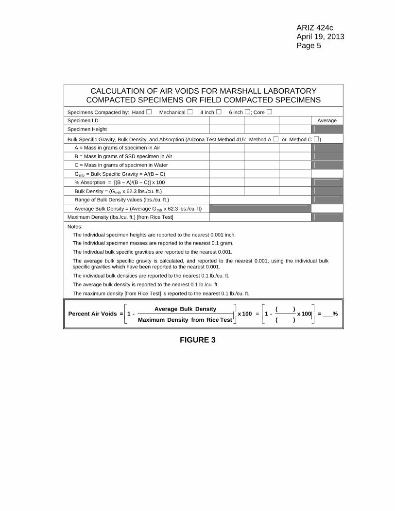
2.1.1.1 An example of the calculations is given in Figure 1. 2.1.1.2 A blank form for perfoming the calculations is given in Figure 3. 2.2 For specimens which are gyratory laboratory compacted, the percent air
voids shall be calculated using the average relative density of the compacted bituminous mixture at Ndesign (AASHTO T 312).

ARIZ 424c April 19, 2013 Page 2 2.2.1 The percent air voids are calculated by the following equation:
Percent Air Voids = (100) – (Average Relative Density, % Gmm, at Ndesign) 2.2.1.1 An example of the calculations is given in Figure 2. 2.2.1.2 A blank form for perfoming the calculations is given in Figure 4. 3. REPORT 3.1 The percent air voids shall be reported to the nearest 0.1%.

ARIZ 424c April 19, 2013 Page 3
CALCULATION OF AIR VOIDS FOR MARSHALL LABORATORY COMPACTED SPECIMENS OR FIELD COMPACTED SPECIMENS
Specimens Compacted by: Hand Mechanical 4 inch 6 inch ; Core
Specimen I.D. 1 2 3 Average
Specimen Height 2.516 2.515 2.519
Bulk Specific Gravity, Bulk Density, and Absorption (Arizona Test Method 415: Method A or Method C ) A = Mass in grams of specimen in Air 1155.9 1155.4 1158.2
B = Mass in grams of SSD specimen in Air 1156.9 1156.3 1159.2
C = Mass in grams of specimen in Water 647.9 649.6 651.8
Gmb = Bulk Specific Gravity = A/(B – C) 2.271 2.280 2.283 2.283
% Absorption = [(B – A)/(B – C)] x 100 0.20 0.18 0.20
Bulk Density = (Gmb x 62.3 lbs./cu. ft.) 141.4 142.0 142.2
Range of Bulk Density values (lbs./cu. ft.) 0.8
Average Bulk Density = (Average Gmb x 62.3 lbs./cu. ft) 142.2
Maximum Density (lbs./cu. ft.) [from Rice Test] 149.4
Notes:
The Individual specimen heights are reported to the nearest 0.001 inch.
The Individual specimen masses are reported to the nearest 0.1 gram.
The Indivdual bulk specific gravities are reported to the nearest 0.001.
The average bulk specific gravity is calculated, and reported to the nearest 0.001, using the individual bulk specific gravities which have been reported to the nearest 0.001.
The individual bulk densities are reported to the nearest 0.1 lb./cu. ft.
The average bulk density is reported to the nearest 0.1 lb./cu. ft.
The maximum density [from Rice Test] is reported to the nearest 0.1 lb./cu. ft.
100 x Test Rice from Density Maximum
Density Bulk Average - 1 = VoidsrPercent Ai
=
100 x149.4
142.2 - 1 = 4.8%
EXAMPLE AIR VOIDS CALCULATION FOR MARSHALL LABORATORY COMPACTED SPECIMENS
FIGURE 1

ARIZ 424c April 19, 2013 Page 4
CALCULATION OF AIR VOIDS FOR GYRATORY LABORATORY COMPACTED SPECIMENS
Specimen I.D. 1 2 Average
hini = Height, in mm, of specimen at Nini (8 gyrations) 128.7 129.3
hdes = Height, in mm, of specimen at Ndes (100 gyrations) 117.0 117.4
hmax = Height, in mm, of specimen at Nmax (160 gyrations) 115.6 116.0
Bulk Specific Gravity and Absorption (Arizona Test Method 415: Method A or Method C )
A = Mass, in grams, of specimen at Nmax in Air 4747.4 4744.6
B = Mass, in grams, of SSD specimen at Nmax in Air 4759.4 4756.0
C = Mass, in grams, of specimen at Nmax in Water 2752.7 2751.2
Gmb = Bulk Specific Gravity of specimen at Nmax C - B
A 2.366 2.367
% Absorption = [(B – A)/(B – C)] x 100 0.60 0.57
Gmm = Maximum Specific Gravity [from Rice Test] 2.449
*Relative Density, %Gmm, of specimen at Nini 86.8 86.7 86.8
*Relative Density, %Gmm, of specimen at Ndes 95.5 95.5 95.5
*Relative Density, %Gmm, of specimen at Nmax 96.6 96.7 96.7
100 x
h x G
h x G G % Density, Relative*
xmm
maxmbmmx
Where: %Gmmx = Relative Density, %Gmm, of specimen at Nini, Ndes, or Nmax
Gmb = Bulk Specific Gravity of specimen at Nmax hmax = Height, in mm, of specimen at Nmax Gmm = Maximum Specific Gravity [from Rice Test] hx = Height of specimen, in mm, at Nini, Ndes, or Nmax
Notes:
The Individual specimen heights are reported to the nearest 0.1 mm.
The Individual specimen masses are reported to the nearest 0.1 gram.
The Indivdual bulk specific gravities are reported to the nearest 0.001.
The maximum specific gravity [from Rice Test] is reported to the nearest 0.001.
The individual relative densities are reported to the nearest 0.1 percent.
The average relative density for each set of specimens (at Nini, Ndes, and Nmax) is calculated, and reported to the nearest 0.1 percent, using the corresponding individual relative densities which have been reported to the nearest 0.1 percent.
Three specimens are used when referee testing is performed.
Percent Air Voids = (100) – (Average Relative Density, % Gmm, at Ndes)
= 100 – 95.5 = 4.5%
EXAMPLE AIR VOIDS CALCULATION FOR GYRATORY LABORATORY COMPACTED SPECIMENS
FIGURE 2
ARIZ 424c April 19, 2013 Page 5
CALCULATION OF AIR VOIDS FOR MARSHALL LABORATORY COMPACTED SPECIMENS OR FIELD COMPACTED SPECIMENS
Specimens Compacted by: Hand Mechanical 4 inch 6 inch ; Core
Specimen I.D. Average
Specimen Height
Bulk Specific Gravity, Bulk Density, and Absorption (Arizona Test Method 415: Method A or Method C ) A = Mass in grams of specimen in Air
B = Mass in grams of SSD specimen in Air
C = Mass in grams of specimen in Water
Gmb = Bulk Specific Gravity = A/(B – C)
% Absorption = [(B – A)/(B – C)] x 100
Bulk Density = (Gmb x 62.3 lbs./cu. ft.)
Range of Bulk Density values (lbs./cu. ft.)
Average Bulk Density = (Average Gmb x 62.3 lbs./cu. ft)
Maximum Density (lbs./cu. ft.) [from Rice Test]
Notes:
The Individual specimen heights are reported to the nearest 0.001 inch.
The Individual specimen masses are reported to the nearest 0.1 gram.
The Indivdual bulk specific gravities are reported to the nearest 0.001.
The average bulk specific gravity is calculated, and reported to the nearest 0.001, using the individual bulk specific gravities which have been reported to the nearest 0.001.
The individual bulk densities are reported to the nearest 0.1 lb./cu. ft.
The average bulk density is reported to the nearest 0.1 lb./cu. ft.
The maximum density [from Rice Test] is reported to the nearest 0.1 lb./cu. ft.
100 x Test Rice from Density Maximum
Density Bulk Average - 1 = VoidsrPercent Ai
=
100 x) (
) ( - 1 = ___%
FIGURE 3

ARIZ 424c April 19, 2013 Page 6
CALCULATION OF AIR VOIDS FOR GYRATORY LABORATORY COMPACTED SPECIMENS
Specimen I.D. Average
hini = Height, in mm, of specimen at Nini (8 gyrations)
hdes = Height, in mm, of specimen at Ndes (100 gyrations)
hmax = Height, in mm, of specimen at Nmax (160 gyrations)
Bulk Specific Gravity and Absorption (Arizona Test Method 415: Method A or Method C )
A = Mass, in grams, of specimen at Nmax in Air
B = Mass, in grams, of SSD specimen at Nmax in Air
C = Mass, in grams, of specimen at Nmax in Water
Gmb = Bulk Specific Gravity of specimen at Nmax C - B
A
% Absorption = [(B – A)/(B – C)] x 100
Gmm = Maximum Specific Gravity [from Rice Test]
*Relative Density, %Gmm, of specimen at Nini
*Relative Density, %Gmm, of specimen at Ndes
*Relative Density, %Gmm, of specimen at Nmax
100 x
h x G
h x G G % Density, Relative*
xmm
maxmbmmx
Where: %Gmmx = Relative Density, %Gmm, of specimen at Nini, Ndes, or Nmax
Gmb = Bulk Specific Gravity of specimen at Nmax hmax = Height, in mm, of specimen at Nmax Gmm = Maximum Specific Gravity [from Rice Test] hx = Height of specimen, in mm, at Nini, Ndes, or Nmax
Notes:
The Individual specimen heights are reported to the nearest 0.1 mm.
The Individual specimen masses are reported to the nearest 0.1 gram.
The Indivdual bulk specific gravities are reported to the nearest 0.001.
The maximum specific gravity [from Rice Test] is reported to the nearest 0.001.
The individual relative densities are reported to the nearest 0.1 percent.
The average relative density for each set of specimens (at Nini, Ndes, and Nmax) is calculated, and reported to the nearest 0.1 percent, using the corresponding individual relative densities which have been reported to the nearest 0.1 percent.
Three specimens are used when referee testing is performed.
Percent Air Voids = (100) – (Average Relative Density, % Gmm, at Ndes)
= (100) – ( _______ ) = ______%
FIGURE 4
ARIZ 427a April 19, 2013 (15 Pages)
ASPHALT BINDER CONTENT OF ASPHALTIC CONCRETE MIXTURES BY THE IGNITION FURNACE METHOD
(A Modification of AASHTO T 308)
1. SCOPE 1.1 This procedure describes the method for determining the percent asphalt
binder content of asphaltic concrete mixtures, by use of an ignition furnace. The aggregate remaining after ignition can be used for sieve analysis, as indicated in Section 6.
1.1.1 This procedure does not address the use of reclaimed asphalt pavement
(RAP) in asphaltic concrete mixtures. See Arizona Test Method 428 when testing is to be performed on asphaltic concrete mixtures containing RAP.
1.2 This test method involves hazardous material, operations, and equipment.
This test method does not purport to address all of the safety concerns associated with its use. It is the responsibility of the user to consult and establish appropriate safety and health practices and determine the applicability of regulatory limitations prior to use.
1.3 See Appendix A1 of the Materials Testing Manual for information
regarding the procedure to be used for rounding numbers to the required degree of accuracy.
1.4 A listing of subsequent Sections and Figures in this procedure is given
below:
Section or Figure #
Title Page #
Section 2 Apparatus 2 Section 3 Sampling 3 Section 4 Calibration 4 Section 5 Procedure 7 Section 6 Sieve Anaylsis of Aggregate 9 Section 7 Report and Example 12
Figure 1 Example Completed Asphaltic Concrete Tabulation - Ignition Furnace Laboratory Card (for the testing performed on a field sample)
14
Figure 2 Blank Asphaltic Concrete Tabulation - Ignition Furnace Laboratory Card 15

ARIZ 427a April 19, 2013 Page 2 2. APPARATUS 2.1 Requirements for the frequency of equipment calibration and verification
are found in Appendix A3 of the Materials Testing Manual. Apparatus for this test procedure shall consist of the following:
2.1.1 Ignition Furnace - a forced-air ignition furnace that heats the sample by
the convection method. The furnace must be capable of heating to temperatures up to 538 C (1000 F), and able to maintain a given temperature at 5 C ( 9 F). The furnace shall have an internal weighing system thermally isolated from the furnace chamber and accurate to 0.1 gram. The balance shall be capable of weighing a 3500 gram sample in addition to the sample baskets. A data collection system shall also be included so that the sample mass loss can be automatically determined to an accuracy of 0.1 gram and displayed during a test. The furnace shall provide a printout that includes, as a minimum, the initial sample mass, sample mass loss, test time, and test temperature. The furnace shall provide an audible alarm and indicator light when the sample mass loss does not exceed 0.01 percent of the total sample mass for three consecutive one minute intervals. A filter capable of reducing emissions to an acceptable level shall also be incorporated into the furnace. The furnace shall be vented into a hood or to the outside and be set up properly so that there are no noticeable odors escaping into the laboratory. The furnace shall have a fan with the capability to pull air through the furnace to expedite the test and to reduce escape of smoke into the laboratory. The furnace shall be equipped so that the door cannot be opened until testing is complete.
2.1.2 Stainless Steel Perforated Baskets - the baskets shall be an appropriate
size that allow the samples to be a thickness which allows air to flow up through and around the sample particles. The sample shall be completely enclosed with screen mesh, perforated stainless steel plate, or other suitable material. Screen mesh or other suitable material with openings of No. 8 has been found to perform well.
2.1.3 Stainless Steel Catch Pan - of sufficient size to hold the sample baskets
so that aggregate particles and melting asphalt binder falling through the screen mesh are caught.
2.1.4 Oven(s) - capable of heating to temperatures up to 350 F, and able to
maintain a given temperature at the tolerances specified herein.

ARIZ 427a April 19, 2013 Page 3 2.1.5 Scale(s) or balance(s) - capable of measuring the maximum mass to be
determined and conforming to the requirements of AASHTO M 231, except the readability and sensitivity of any balance or scale utilized shall be at least 0.1 gram.
2.1.6 Safety Equipment - safety glasses or face shield, high temperature
gloves, and long sleeve jacket. Additionally, a heat resistant surface capable of withstanding 1200 F and a protective cage capable of surrounding the sample baskets shall be provided.
2.1.7 Miscellaneous Equipment - a pan larger than the sample basket(s) for
transferring samples after ignition, spatulas, bowls, spoons, and wire brushes.
2.1.8 Mixing apparatus - Mechanical mixing is recommended; 20 quart
capacity mixer is required. (Hand mixing may be performed if desired.) 2.1.9 Thermometer - with a temperature range of 50 to 500 F. 2.1.10 Hot plate - capable of heating to temperatures up to 350 F, and able to
maintain a given temperature at 5 F. 2.1.11 For performing sieve analysis, apparatus as specified in Arizona Test
Method 201. 3. SAMPLING 3.1 For preparing calibration samples, obtain representative samples of
aggregates in accordance with Arizona Test Method 105. Samples shall be sufficiently large to provide enough material for calibration testing. The samples shall be adequately dried, if necessary, to a free-flowing condition in the portion passing the 4.75 mm (No. 4) sieve.
3.2 For testing field samples of asphaltic concrete, obtain a representative
sample of the freshly produced mix in accordance with Arizona Test Method 104. Obtain representative test samples, in accordance with the appropriate sections of Arizona Test Method 416, for the determination of moisture content (if required) and asphalt binder content.
3.2.1 The size of the asphalt binder content test sample shall be within 150
grams of the sample size used for calibration and must also conform to the mass requirement shown in Table 1. When the mass of the test sample exceeds the capacity of the equipment used, the test sample shall

ARIZ 427a April 19, 2013 Page 4
be divided into suitable increments, tested, and the results appropriately combined.
TABLE 1
Size of Test Sample
Nominal Maximum Aggregate Size (See Note)
Mass of Sample, grams
1-1/2 in. 4000 – 4500 1 in. 3000 – 3500
3/4 in. 2000 – 2500 1/2 in. 1500 – 2000 3/8 in. 1200 – 1700 No. 4 1200 – 1700
Note: The smallest sieve opening through which the entire amount of material, by specification, is permitted to pass.
4. CALIBRATION 4.1 Asphalt binder content results may be affected by the type of aggregate
and binder in the mixture. A calibration factor for the asphalt binder content must be established for each mix design. Certain aggregate types may result in an unusually high calibration factor and erroneous gradation results due to aggregate breakdown. Such mixes should be calibrated and tested at a lower temperature as described in Subsection 4.14.
4.2 Dry the aggregate samples to constant mass at 290 10 F. Allow the
material to cool. 4.3 Screen the aggregate stockpile samples and separate into individual sizes
for No. 8 and larger, and minus No. 8 material.
Note: In lieu of screening the aggregate sample for each individual stockpile, a bulk-batched sample may be used as described in Subsection 4.3.1.
4.3.1 Using the aggregate stockpile percentages shown in the mix design
composite, the material from the individual stockpiles may be bulk-batched in a single sample of an adequate amount of material necessary to prepare the required calibration samples. Screen the bulk-batched material and separate into individual sizes for No. 8 and larger, and minus No. 8 material.

ARIZ 427a April 19, 2013 Page 5 4.4 Using the individual sizes of aggregate for No. 8 and larger, and minus
No. 8 material, as obtained either by screening the material from the individual aggregate stockpiles or by screening the the bulk-batched sample, weigh up four aggregate samples representative of the mix design gradation without mineral admixture. These samples will be used for a gradation check, two calibration samples, and a butter mix. The appropriate type and quantity of mineral admixture (by weight of aggregate) shall be added to the aggregate, and thoroughly blended. The weight of the gradation check sample shall conform to the requirements of Table 1. The weight of the two calibration samples and the butter mix shall be such that when the required amount of asphalt binder is added, they conform to the requirements of Table 1.
4.5 Using the aggregate and mineral admixture sample prepared for the
gradation check, perform a gradation analysis according to Section 6 to determine the actual gradation. The gradation shall be representative of the mix design gradation with mineral admixture. If the gradation is not representative of the mix design, four new aggregate and mineral admixture samples shall be prepared.
4.6 Using the remaining three aggregate and mineral admixture samples, two
calibration samples and a butter mix are prepared as described below at the design asphalt binder content. The asphalt binder grade and type shall be the same as will be used in the asphalt concrete mixture to be tested during production. Heat the samples to the laboratory mixing temperature prescribed in the mix design. (See Note following Subsection 4.7). Allow the samples to cool. Weigh and determine the mass of each sample to the nearest 0.1 gram. If mass is lost during the heating of the samples, do not add make-up material, as this will change the gradation of the samples. The percent asphalt binder content is based on the mass of total mix. For each sample, the weight of asphalt binder to be used is determined by the following:
Binder Asphalt
of Percent x
Binder Asphalt
of Percent - 100
AdmixtureMineral and
Aggregateof Weight
= Binder Asphalt
of t Weigh
4.7 All bowls, sample pans, and mixing tools shall be preheated to
approximately the laboratory mixing temperature prescribed in the mix design. At the time mixing of the samples begins, the temperature of the asphalt binder, aggregate, and mineral admixture shall be in accordance with the prescribed laboratory mixing temperature 5 F. Each individual

ARIZ 427a April 19, 2013 Page 6
sample shall be thoroughly mixed. All samples shall be mixed at the same mixing temperature 5 F.
Note: If the mix design laboratory mixing temperature is not
specified, a temperature of 300 5 F shall be used for mixes which do not use asphalt-rubber, and 325 5 F for asphalt-rubber mixes.
4.8 Preheat the ignition furnace to 538 5 C (1000 9 F), or as modified in
Subsection 4.14. Do not preheat the sample basket. 4.9 Weigh and record the mass of the basket assembly to the nearest
0.1 gram. 4.10 The freshly mixed samples may be placed directly in the sample basket
assembly. If the samples are allowed to cool, they must be reheated in a 290 10 F oven for 25 minutes.
4.11 Test samples in accordance with Subsections 5.6 through 5.14. 4.12 If the difference between the measured asphalt binder content of the two
samples exceeds 0.07, repeat the test using two additional samples, and from the four results discard the high and the low values.
4.13 Subtract the actual asphalt binder content for each of the two samples
from their respective measured asphalt binder content. The asphalt binder content calibration factor is the average of the two resultant values expressed in percent by mass of the asphalt mixture.
4.14 If the asphalt binder content calibration factor exceeds 1.0 percent,
lower the test temperature to 482 5 C (900 9 F) and repeat the test to determine a new calibration factor. If the calibration factor continues to exceed 1.0 percent, lower the test temperature to 427 5 C (800 9 F) and repeat the test to determine a new calibration factor. Use the calibration factor obtained at 427 5 C (800 9 F) even if it exceeds 1.0 percent.
4.15 Perform a gradation analysis on the residual aggregate as indicated in
Section 6. Subtract the actual percent passing the No. 200 sieve for each sample from the measured percent passing the No. 200 sieve (as determined in Subsection 4.5). Determine the average of the two values. If the resultant average value is greater than 0.50, an aggregate gradation correction factor (equal to the resultant average value) for the

ARIZ 427a April 19, 2013 Page 7
passing No. 200 material may be applied to the production field sample test results.
5. PROCEDURE 5.1 The moisture content of the asphaltic concrete shall be determined in
accordance with Arizona Test Method 406. The moisture content sample shall be obtained at the same time and subjected to the same treatment prior to testing as the asphalt binder content test sample. As an alternate to performing the moisture determination, the test sample may be dried to a constant mass in an oven at 290 10 F.
5.2 Preheat the ignition furnace to 538 5 C (1000 9 F), or to the alternate
temperature determined during the calibration (Subsection 4.14). Do not preheat the sample basket. Record the furnace temperature set point prior to the initiation of the test.
5.3 Record the asphalt binder content calibration factor, determined in
accordance with Subsections 4.12 through 4.14, for the specific mix to be tested.
5.4 Weigh and record the mass of the basket assembly to the nearest
0.1 gram. 5.5 Obtain the asphalt binder content test sample in accordance with
Subsection 3.2, ensuring that the size of the test sample is within 150 grams of the sample size used for calibration and that the test sample conforms to the requirements shown in Table 1.
5.6 Evenly distribute the test sample over the center of the sample basket(s)
and level the material. Use a spatula or trowel to pull material approximately one inch away from the outside edge of basket(s).
5.7 Weigh and record the mass of the sample and basket assembly to the
nearest 0.1 gram. 5.8 Calculate and record the initial mass of the sample to the nearest
0.1 gram. 5.9 Set the ignition furnace controller print mode to give a printout of the test
data required in Subsection 2.1.1. Input the initial mass of the sample into the ignition furnace controller. Verify that the correct mass has been entered.

ARIZ 427a April 19, 2013 Page 8 5.10 Open the furnace door and place the sample and basket assembly so that
it is centered in the chamber. After assuring that the sample basket assembly is not in contact with any wall, close the door. Initiate the test by pressing the start button. This will lock the furnace door and start testing.
5.11 Allow the test to continue until the stable light and audible stable indicator
indicates the test is complete. The test is deemed complete when the measured mass loss does not exceed 0.01 percent of the sample mass for three consecutive one minute intervals. If required, press the stop button. This will unlock the furnace door and cause the printer to print out the test results.
5.12 Open the furnace door and remove the sample and basket assembly.
Allow the sample to cool 30 5 minutes in the basket assembly. Weigh and record the mass of the sample and basket assembly after ignition to the nearest 0.1 gram.
5.13 Calculate and record the mass of sample after ignition to the nearest
0.1 gram. 5.14 Calculate and record the corrected asphalt binder content of the sample,
to the nearest 0.01%, as follows:
%M - C - 100 x W
WW = %AC F
i
A i
-
Where: %AC = measured (corrected) asphalt binder content in percent by mass of the sample
Wi = mass of the sample prior to ignition WA = mass of the sample after ignition CF = asphalt binder content calibration factor, percent by mass of the sample %M = percent moisture in the sample
Note: During calibration, CF and %M are zero.
5.14.1 If an ignition furnace correction (tank stab correction) is made, the %AC
determined in Subsection 5.14 is adjusted by that correction. 5.15 Attach the original printed ticket to the back of the card. 5.16 Empty the contents of the baskets into a flat pan. Use a small wire sieve
brush to ensure that any residual fines are removed from the

ARIZ 427a April 19, 2013 Page 9
baskets. Take care not to lose any material, as this will affect gradation results.
5.17 If needed, perform a gradation analysis of the residual aggregate
according to Section 6. 6. SIEVE ANALYSIS OF AGGREGATE 6.1 If required, the aggregate shall be subjected to sieve analysis as
described below. The coarse sieving shall be performed in accordance with Subsection 6.2, and the fine sieving in accordance with Subsection 6.3. The quantity of material on a given sieve at the completion of sieving shall not exceed the amount shown in Table 2.
TABLE 2
Maximum Mass Allowed (grams) Sieve
Size
Maximum Mass Allowed (grams/sq. in.) 8 inch
Diameter Sieve
12 inch Diameter
Sieve 1-1/2” 25 --- 2827
1” 18 --- 2036 3/4” 14 --- 1583 1/2” 10 --- 1131 3/8” 8 --- 905 1/4” 6 --- 679
No. 4 5 --- 565 No. 8 and smaller 4 201 452
6.2 The coarse sieving of the aggregate shall be performed as follows: 6.2.1 Weigh and record the mass of the sample to be sieved to the nearest
gram. Place sample on the top sieve of a nest of 12 inch sieves. The nest of sieves shall consist of sieves starting with the smallest size sieve that 100% of the material will pass, down through and including the No. 8 sieve and pan. Place lid on nested sieves and screen the material by either mechanical or hand shaking, until not more than 0.5 percent by mass of sample passes any sieve during one minute.

ARIZ 427a April 19, 2013 Page 10 6.2.2 Weigh and record separately, to the nearest gram, the mass of the
material retained on the individual sieves and in the pan. The material retained in the pan is recorded as the minus No. 8 material.
6.2.3 Do not discard any of the sieved material until the sum of the individual
masses is compared to the mass of the sample prior to sieving. If the difference between the two masses is less than or equal to 1.0% of the mass of the sample prior to sieving, an adjustment in mass shall be made on the sieve which has the largest mass retained, except no adjustment shall be made on the minus No. 8 material. If the difference is greater than 1.0%, the sample shall be recombined, resieved, and carefully reweighed.
6.2.4 Determine the coarse sieve factor by dividing 100 by the total mass
sieved. Record the factor to six decimal places. 6.2.5 The percent passing for each sieve in the coarse sieve analysis is
determined by multiplying the mass retained on that sieve by the coarse sieve factor, and subtracting the result from the unrounded % passing for the next larger sieve. Values for "mass retained multiplied by the coarse sieve factor" and "percent passing each sieve" shall be determined and used in the calculations to six decimal places. The percent passing value for each sieve is recorded in the sieve analysis to the nearest percent.
6.2.6 As a check on the coarse sieve analysis, multiply the mass of minus No. 8
material by the coarse sieve factor. The result of this calculation, rounded to the nearest percent, should be the same as the value for percent passing the No. 8 sieve determined in Subsection 6.2.5 above.
6.2.7 The material passing the No. 8 sieve is split, if necessary, to obtain a
minimum 500 gram sample for fine sieving; however, the sample size may be less than 500 grams if a minimum of 500 grams is not obtained from coarse sieving. If less than 800 grams passes the No. 8 sieve, the entire amount shall be subjected to fine sieving. The mass of the sample for fine sieving is recorded to the nearest gram as mass of pass No. 8 split.
6.3 The elutriation and fine sieving of the pass No. 8 material shall be
performed as follows: 6.3.1 Subject sample to elutriation through a No. 200 screen either by hand or
mechanical washing.

ARIZ 427a April 19, 2013 Page 11 6.3.2 Dry sample to constant mass, allow to cool, then weigh and record the
dry mass to the nearest gram. 6.3.3 Place sample on the top sieve of a nest of fine sieves. The nest of
sieves shall consist of sieves starting with the No. 10 sieve, down through and including the No. 200 sieve and pan. Place lid on nested sieves and screen the material by either mechanical or hand shaking, until not more than 0.5 percent by mass of sample passes any sieve during one minute.
6.3.4 Weigh and record separately, to the nearest gram, the mass of material
retained on the individual sieves and in the pan. 6.3.5 Do not discard any of the sieved material until the sum of the individual
masses is compared to the mass of the sample prior to sieving. If the difference between the two masses is less than or equal to 1.0% of the mass of the sample prior to sieving, an adjustment in mass shall be made on the sieve which has the largest mass retained, except no adjustment shall be made on the minus No. 200 material. If the difference is greater than 1.0%, the sample shall be recombined, resieved, and carefully reweighed.
6.3.6 Determine and record elutriation to nearest gram by determining the
difference between the dry mass and the mass of the pass No. 8 split. 6.3.7 Determine a factor for calculating the fine sieve analysis by dividing the
percent passing the No. 8 sieve (recorded to the nearest percent) by the mass of pass No. 8 split. Record the factor to six decimal places. If all the pass No. 8 material from coarse sieving was subjected to elutriation and fine sieving, a fine sieve factor is not determined. Rather, the coarse sieve factor is utilized and the calculation of the percent passing each sieve is continuous through the entire sieve analysis.
6.3.8 The percent passing for each sieve in the fine sieve analysis is determined
by multiplying the mass retained on that sieve by the fine sieve factor, and subtracting the result from the unrounded % passing the next larger sieve, with the exception of the percent passing the No. 8 which has previously been recorded to the nearest percent. Values for "mass retained multiplied by the fine sieve factor" and "percent passing each sieve" shall be determined and used in the calculations to six decimal places. The percent passing value for each sieve is recorded in the sieve analysis to the nearest percent, except the percent passing the No. 200 sieve is recorded to the nearest 0.1 percent.

ARIZ 427a April 19, 2013 Page 12 6.3.9 As a check on the fine sieve analysis, the mass of material passing the
No. 200 sieve is added to the elutriation mass, and this total is multiplied by the fine sieve factor. The result of this calculation, rounded to the nearest 0.1 percent, should be the same as the value for the percent passing the No. 200 sieve determined in Subsection 6.3.8 above.
6.3.10 If an aggregate gradation correction factor is utilized, the percent passing
the No. 200 sieve shall be adjusted by subtracting the correction factor determined in Subsection 4.15.
6.4 Other methods may be used that differ from that specified in Subsections
6.2 and 6.3 above to determine % passing each sieve, so long as the method utilized has been proven to give equivalent results. However, any procedure which includes recording percent retained values prior to completing the calculation of all percent passing values is not allowed.
7. REPORT AND EXAMPLE 7.1 Report test information on the Asphaltic Concrete Tabulation – Ignition
Furnace laboratory card. An example for the testing performed on a field sample is shown in Figure 1. Only the portion of the laboratory card relevant to the ignition furnace test is used for the example. A blank Asphaltic Concrete Tabulation – Ignition Furnace laboratory card is shown in Figure 2.
7.1.1 Mass of basket assembly. 7.1.2 Mass of sample and basket assembly. 7.1.3 Calculated initial mass of the sample. 7.1.4 Mass of sample and basket assembly after ignition. 7.1.5 Calculated mass of sample after ignition. 7.1.6 Asphalt binder content calibration factor. 7.1.7 Percent moisture from moisture test, if one was performed. 7.1.8 Corrected percent asphalt binder content. 7.1.9 Elapsed time of test.

ARIZ 427a April 19, 2013 Page 13 7.1.10 Name of the operator. 7.1.11 Sample test date. 7.1.12 Design percent asphalt binder content. 7.2.13 Ignition furnace set temperature. 7.2.14 If determined, the sieve analysis of the residual aggregate (corrected for
passing the No. 200 sieve if applicable).

ARIZ 427a April 19, 2013 Page 14
FIGURE 1
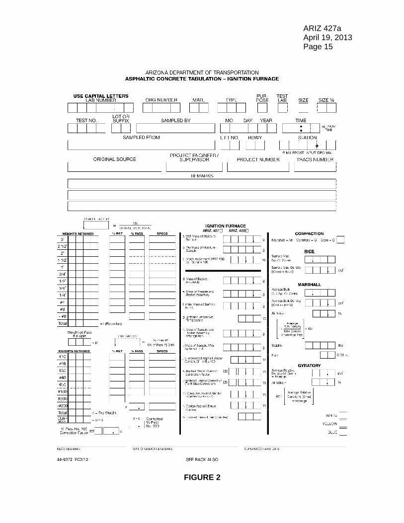
ARIZ 427a April 19, 2013 Page 15
FIGURE 2


ARIZ 428 April 19, 2013 (33 Pages)
ASPHALT BINDER CONTENT OF ASPHALTIC CONCRETE MIXTURES CONTAINING RECLAIMED ASPHALT
PAVEMENT (RAP) BY THE IGNITION FURNACE METHOD
(A Modification of AASHTO T 308)
1. SCOPE 1.1 This procedure describes the method for determining the percent asphalt
binder content of asphaltic concrete mixtures containing reclaimed asphalt pavement (RAP), by use of an ignition furnace. The aggregate remaining after ignition can be used for sieve analysis, as indicated in Section 6.
1.1.1 The gradation, moisture content, and binder content of the RAP material
are determined as described in Appendix A of this test method. The determination of the RAP aggregate gradation is also discussed in Appendix A. The procedure for determining the RAP binder content correction factor is described in Appendix B.
1.1.2 This procedure addresses the use of reclaimed asphalt pavement (RAP)
in asphaltic concrete mixtures. See Arizona Test Method 427 when testing is to be performed on asphaltic concrete mixtures which do not contain RAP.
1.2 This test method involves hazardous material, operations, and equipment.
This test method does not purport to address all of the safety concerns associated with its use. It is the responsibility of the user to consult and establish appropriate safety and health practices and determine the applicability of regulatory limitations prior to use.
1.3 See Appendix A1 of the Materials Testing Manual for information
regarding the procedure to be used for rounding numbers to the required degree of accuracy.
1.4 A listing of subsequent Sections and Figures in this procedure is given
below:

ARIZ 428 April 19, 2013 Page 2
Section or Figure #
Title Page #
Section 2 Apparatus 2 Section 3 Sampling 4 Section 4 Calibration 4 Section 5 Procedure 13 Section 6 Sieve Anaylsis of Aggregate 15 Section 7 Report and Example 18 Figure 1 Example Ignition Furnace Calibration Mix Design Weigh-Up Information 20
Figure 2 Example Ignition Furnace Calibration Weigh-Up Requirements for Gradation Check
21
Figure 3 Example Ignition Furnace Calibration Weigh-Up Requirements for Burn 1 and 2
22
Figure 4 Example Completed Asphaltic Concrete Tabulation - Ignition Furnace Laboratory Card (for the testing performed on a field sample)
23
Figure 5 Blank Asphaltic Concrete Tabulation - Ignition Furnace Laboratory Card 24
Appendix A Determination of Gradation, Moisture Content, and Binder Content of the RAP Material
25
Figure 6 Example Completed RAP Material Tabulation - Ignition Furnace Laboratory Card
29
Figure 7 Blank RAP Material Tabulation - Ignition Furnace Laboratory Card 30 Apppendix
B Determination of the Rap Binder Correction Factor 31
Figure 8 Example Completed RAP Binder Content Correction Factor Laboratory Card 32 Figure 9 Blank RAP Binder Content Correction Factor Laboratory Card 33
2. APPARATUS 2.1 Requirements for the frequency of equipment calibration and verification
are found in Appendix A3 of the Materials Testing Manual. Apparatus for this test procedure shall consist of the following:
2.1.1 Ignition Furnace - a forced-air ignition furnace that heats the sample by
the convection method. The furnace must be capable of heating to temperatures up to 538 C (1000 F), and able to maintain a given temperature at 5 C ( 9 F). The furnace shall have an internal weighing system thermally isolated from the furnace chamber and accurate to 0.1 gram. The balance shall be capable of weighing a 3500 gram sample in addition to the sample baskets. A data collection system shall also be included so that the sample mass loss can be automatically determined to an accuracy of 0.1 gram and displayed during a test. The furnace shall provide a printout that includes, as a minimum, the initial sample mass, sample mass loss, test time, and test temperature. The furnace shall provide an audible alarm and indicator light when the sample mass loss does not exceed 0.01 percent of the total sample mass for three consecutive one minute intervals. A filter capable of reducing

ARIZ 428 April 19, 2013 Page 3
emissions to an acceptable level shall also be incorporated into the furnace. The furnace shall be vented into a hood or to the outside and be set up properly so that there are no noticeable odors escaping into the laboratory. The furnace shall have a fan with the capability to pull air through the furnace to expedite the test and to reduce escape of smoke into the laboratory. The furnace shall be equipped so that the door cannot be opened until testing is complete.
2.1.2 Stainless Steel Perforated Baskets - the baskets shall be an appropriate
size that allow the samples to be a thickness which allows air to flow up through and around the sample particles. The sample shall be completely enclosed with screen mesh, perforated stainless steel plate, or other suitable material. Screen mesh or other suitable material with openings of No. 8 has been found to perform well.
2.1.3 Stainless Steel Catch Pan - of sufficient size to hold the sample baskets
so that aggregate particles and melting asphalt binder falling through the screen mesh are caught.
2.1.4 Oven(s) - capable of heating to temperatures up to 350 F, and able to
maintain a given temperature at the tolerances specified herein. 2.1.5 Scale(s) or balance(s) - capable of measuring the maximum mass to be
determined and conforming to the requirements of AASHTO M 231, except the readability and sensitivity of any balance or scale utilized shall be at least 0.1 gram.
2.1.6 Safety Equipment - safety glasses or face shield, high temperature
gloves, and long sleeve jacket. Additionally, a heat resistant surface capable of withstanding 1200 F and a protective cage capable of surrounding the sample baskets shall be provided.
2.1.7 Miscellaneous Equipment - a pan larger than the sample basket(s) for
transferring samples after ignition, spatulas, bowls, spoons, and wire brushes.
2.1.8 Mixing apparatus - Mechanical mixing is recommended; 20 quart
capacity mixer is required. (Hand mixing may be performed if desired.) 2.1.9 Thermometer - with a temperature range of 50 to 500 F. 2.1.10 Hot plate - capable of heating to temperatures up to 350 F, and able to
maintain a given temperature at 5 F.
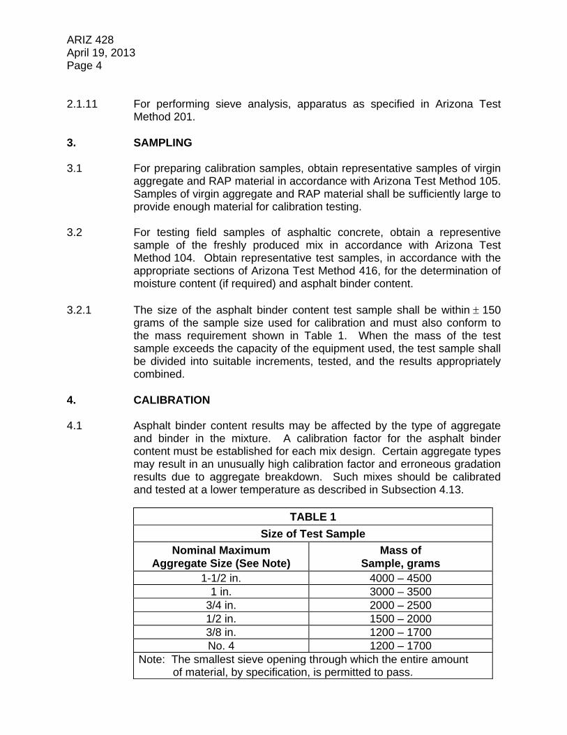
ARIZ 428 April 19, 2013 Page 4 2.1.11 For performing sieve analysis, apparatus as specified in Arizona Test
Method 201. 3. SAMPLING 3.1 For preparing calibration samples, obtain representative samples of virgin
aggregate and RAP material in accordance with Arizona Test Method 105. Samples of virgin aggregate and RAP material shall be sufficiently large to provide enough material for calibration testing.
3.2 For testing field samples of asphaltic concrete, obtain a representive
sample of the freshly produced mix in accordance with Arizona Test Method 104. Obtain representative test samples, in accordance with the appropriate sections of Arizona Test Method 416, for the determination of moisture content (if required) and asphalt binder content.
3.2.1 The size of the asphalt binder content test sample shall be within 150
grams of the sample size used for calibration and must also conform to the mass requirement shown in Table 1. When the mass of the test sample exceeds the capacity of the equipment used, the test sample shall be divided into suitable increments, tested, and the results appropriately combined.
4. CALIBRATION 4.1 Asphalt binder content results may be affected by the type of aggregate
and binder in the mixture. A calibration factor for the asphalt binder content must be established for each mix design. Certain aggregate types may result in an unusually high calibration factor and erroneous gradation results due to aggregate breakdown. Such mixes should be calibrated and tested at a lower temperature as described in Subsection 4.13.
TABLE 1
Size of Test Sample
Nominal Maximum Aggregate Size (See Note)
Mass of Sample, grams
1-1/2 in. 4000 – 4500 1 in. 3000 – 3500
3/4 in. 2000 – 2500 1/2 in. 1500 – 2000 3/8 in. 1200 – 1700 No. 4 1200 – 1700
Note: The smallest sieve opening through which the entire amount of material, by specification, is permitted to pass.

ARIZ 428 April 19, 2013 Page 5 4.2 Spread the RAP material from each individual RAP stockpile to be used
for the calibration in separate pans at 1 to 1-1/2 inches in depth and dry overnight at 140 10 F, and continue drying until the mass, after successive one-half hour periods of drying, indicates no change in mass. Allow the material to cool. Screen the RAP material from the individual stockpiles and separate into individual sizes for No. 8 and larger sieves, and minus No. 8 material. The RAP material shall be screened for 5 minutes 15 seconds per Arizona Test Method 240 to prevent excessive breakdown of the RAP agglomerations.
4.3 Dry the individual virgin aggregate stockpile samples to constant mass at
290 10 F. Allow the material to cool. Screen the virgin aggregate from the individual stockpiles and separate into individual sizes for No. 8 and larger sieves, and minus No. 8 material.
Note: In lieu of drying and screening the virgin aggregate samples
for each individual stockpile, a bulk-batched sample may be used as described in Subsection 4.3.1.
4.3.1 Using the adjusted stockpile percentages shown in Mix Design
Composite #2 (Virgin Aggregate Composite), the material from the individual stockpiles may be bulk-batched into a single sample of an adequate amount of material necessary to prepare the required calibration samples. Dry the bulk-batched sample to constant mass at 290 10 F. Allow the material to cool. Screen the bulk-batched material and separate into individual sizes for No. 8 and larger sieves, and minus No. 8 material.
4.4 The RAP aggregate [extracted aggregate (AASHTO T 164 - Method A)
from the RAP material] shall be dried to constant mass at 290 10 F. Allow the material to cool. Screen the RAP aggregate material from the individual stockpiles and separate into individual sizes for No. 8 and larger sieves, and minus No. 8 material.
Note: The batching of samples described below in Subsection 4.5
and Subsection 4.6 is based on the mix design weigh-up information, as shown in the example in Figure 1.
4.5 A gradation check sample is batched using:
The virgin mineral aggregate component (individual stockpile material or bulk-batched material), which has been screened into individual sizes for No. 8 and larger sieves, and minus No. 8 material.

ARIZ 428 April 19, 2013 Page 6
The RAP aggregate component, which has been screened into individual sizes for No. 8 and larger sieves, and minus No. 8 material.
Mineral admixture.
4.5.1 Batch the virgin aggregate portion to Mix Design Composite #2 (Virgin
Aggregate Composite). If the individual virgin aggregate stockpiles were screened, batch to the individual accumulative weights required for each individual stockpile, as shown in the example in Figure 2. If bulk-batched virgin aggregate material is used, batch to the accumulative weights required for the total batch weight as shown in the example in Figure 2.
4.5.1.1 The weight of the virgin aggregate portion is determined as follows:
taW x 100
praT - 100 vaW
Where: Wva = Weight of virgin aggregate Tpra = Total percent of RAP aggregate in mix design Wta = Weight of total aggregate desired (combined virgin aggregate and RAP aggregate) Example:
grams 1650 (2200) x 100
10) (15 - 100 Wva
4.5.2 Batch the RAP aggregate portion to Mix Design Composite #1 (Virgin
Aggregate and RAP Aggregate Composite), utilizing the accumulative weights required for each individual RAP aggregate material, as shown in the example in Figure 2.
4.5.2.1 The weight of RAP aggregate portion required for each RAP stockpile is
determined as follows:
taW x 100Pra raW
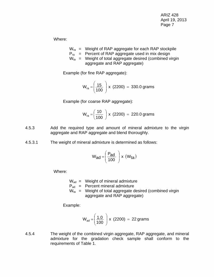
ARIZ 428 April 19, 2013 Page 7 Where: Wra = Weight of RAP aggregate for each RAP stockpile Pra = Percent of RAP aggregate used in mix design Wta = Weight of total aggregate desired (combined virgin aggregate and RAP aggregate) Example (for fine RAP aggregate):
grams 330.0 (2200) x 10015 Wra
Example (for coarse RAP aggregate):
grams 220.0 (2200) x 100
10 Wra
4.5.3 Add the required type and amount of mineral admixture to the virgin
aggregate and RAP aggregate and blend thoroughly. 4.5.3.1 The weight of mineral admixture is determined as follows:
taW x 100adP
adW
Where: Wad = Weight of mineral admixture Pad = Percent mineral admixture Wta = Weight of total aggregate desired (combined virgin aggregate and RAP aggregate) Example:
grams 22 (2200) x 1001.0 Wad
4.5.4 The weight of the combined virgin aggregate, RAP aggregate, and mineral
admixture for the gradation check sample shall conform to the requirements of Table 1.

ARIZ 428 April 19, 2013 Page 8 4.5.5 Perform a gradation analysis on the gradation check sample in
accordance with Section 6 to determine the actual gradation. 4.6 Two calibration (burn) samples and also a “butter mix” sample are batched
using:
The virgin mineral aggregate component (individual stockpile material or bulk-batched material), which has been screened into individual sizes for No. 8 and larger sieves, and minus No. 8 material.
The RAP material (dry screened RAP) component, which has been
screened into individual sizes for No. 8 and larger sieves, and minus No. 8 material.
Mineral admixture.
4.6.1 Batch the virgin aggregate portion to Mix Design Composite #2 (Virgin
Aggregate Composite). If the individual virgin aggregate stockpiles were screened, batch to the individual accumulative weights required for each individual stockpile, as shown in the example in Figure 3. If bulk-batched virgin aggregate material is used, batch to the accumulative weights required for the total batch weight as shown in as shown in the example in Figure 3.
4.6.1.1 The weight of the virgin aggregate portion is detemined as shown in
Subsection 4.5.1.1. 4.6.2 Add the required type and amount of mineral admixture to each of the
batched virgin aggregate samples and blend thoroughly. 4.6.2.1 The weight of the mineral admixture is detemined as shown in
Subsection 4.5.3.1. 4.6.3 Form a shallow crater in the center of each of the blended virgin
aggregate/mineral admixture samples. 4.6.4 Batch the dry screened RAP portion to Mix Design Composite #3 (Virgin
Aggregate and Dry Screened RAP Composite), utilizing the accumulative weights required for each individual dry screened RAP material, as shown in the example in Figure 3.
4.6.4.1 The weight of the dry screened RAP portion from each RAP stockpile is
determined as follows:

ARIZ 428 April 19, 2013 Page 9
100Pbr - 1
Wra rapW
Where: Wrap = Weight of dry screened RAP from each RAP stockpile Wra = Weight of RAP aggregate for each RAP stockpile Pbr = Percent binder content of each RAP stockpile Example (for fine RAP stockpile):
grams 350.4
1005.82 - 1
330.0 Wrap
Example (for coarse RAP stockpile):
grams 227.8
1003.43 - 1
220.0 Wrap
4.6.5 Place the dry screened RAP material in the crater formed in each of the
blended virgin aggregate/mineral admixture samples. 4.6.6 The weight of the combined virgin aggregate, dry screened RAP, and
mineral admixture for each calibration sample and the “butter mix” sample shall be such that when the required amount of virgin asphalt binder is added, they conform to the requirements of Table 1.
Note: It is recommended that an initial calibration sample be
prepared and tested in accordance with the requirements of Subsection 4.6.7 prior to the preparation of additional samples. Doing so may help avoid the waste of the limited amount of dry screened RAP material.
4.6.7 Prior to the addition of the virgin binder, record the weight of the combined
virgin aggregate, dry screened RAP, and mineral admixture for each calibration sample to the nearest 0.1 gram as the “Weight of Initial Charge Before Drying”. Dry each charge to constant mass at 290 10 F, allow to cool, and record the weight to the nearest 0.1 gram as the “Weight of Initial Charge After Drying”. If the loss from drying is greater than
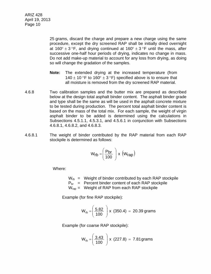
ARIZ 428 April 19, 2013 Page 10
25 grams, discard the charge and prepare a new charge using the same procedure, except the dry screened RAP shall be initially dried overnight at 160 3 F, and drying continued at 160 3 F until the mass, after successive one-half hour periods of drying, indicates no change in mass. Do not add make-up material to account for any loss from drying, as doing so will change the gradation of the samples.
Note: The extended drying at the increased temperature (from
140 10 F to 160 3 F) specified above is to ensure that all moisture is removed from the dry screened RAP material.
4.6.8 Two calibration samples and the butter mix are prepared as described
below at the design total asphalt binder content. The asphalt binder grade and type shall be the same as will be used in the asphalt concrete mixture to be tested during production. The percent total asphalt binder content is based on the mass of the total mix. For each sample, the weight of virgin asphalt binder to be added is determined using the calculations in Subsections 4.5.1.1, 4.5.3.1, and 4.5.6.1 in conjunction with Subsections 4.6.8.1, 4.6.8.2, and 4.6.8.3.
4.6.8.1 The weight of binder contributed by the RAP material from each RAP
stockpile is determined as follows:
rapW x 100Pbr rbW
Where: Wrb = Weight of binder contributed by each RAP stockpile Pbr = Percent binder content of each RAP stockpile Wrap = Weight of RAP from each RAP stockpile Example (for fine RAP stockpile):
grams 20.39 (350.4) x 1005.82 Wrb
Example (for coarse RAP stockpile):
grams 7.81 (227.8) x 1003.43 Wrb

ARIZ 428 April 19, 2013 Page 11 4.6.8.2 The weight of total binder is determined as follows:
tbP x tbP - 100
ad W wraT vaW tbW
Where: Wtb = Weight of total binder Wva = Weight of virgin aggregate Twra = Total weight of RAP aggregate Wad = Weight of mineral admixture Ptb = Percent total binder (mix design percent binder content) Example:
grams 126.84 (5.4) x 5.4 - 100
22 220) (330 1650 Wtb
4.6.8.3 The weight of virgin asphalt binder to be added is determined as follows:
trbW - tbW vbW
Where: Wvb = Weight of virgin asphalt binder to be added Wtb = Weight of total binder Wtrb = Total weight of binder contributed by RAP stockpiles Example:
7.81) (20.39 - (126.84) Wvb 98.6 grams
Note: If desired, the percent of the total binder which is contributed
by RAP can be calculated as follows:
(100) x tbWtrbW
RAPby
dContribute Binder
Total of Percent

ARIZ 428 April 19, 2013 Page 12 Where: Wtrb = Total weight of binder contributed by RAP stockpiles Wtb = Weight of total binder required Example:
(100) x
126.847.81) (20.39
RAPby
dContribute Binder
Total of Percent
22.23%
4.6.8.4 All bowls, sample pans, and mixing tools shall be preheated to
approximately the laboratory mixing temperature prescribed in the mix design. At the time mixing of the samples begins, the temperature of the asphalt binder, virgin aggregate, RAP, and mineral admixture shall be in accordance with the prescribed laboratory mixing temperature 5 F. Each individual sample shall be thoroughly mixed. All samples shall be mixed at the same mixing temperature 5 F.
Note: If the mix design laboratory mixing temperature is not
specified, a temperature of 300 5 F shall be used. 4.7 Preheat the ignition furnace to 538 5 C (1000 9 F), or as modified in
Subsection 4.13. Do not preheat the sample basket. 4.8 Weigh and record the mass of the basket assembly to the nearest
0.1 gram. 4.9 The freshly mixed samples may be placed directly in the sample basket
assembly. If the samples are allowed to cool, they must be reheated in a 290 10 F oven for 25 minutes.
4.10 Test samples in accordance with Subsections 5.6 through 5.14. 4.11 If the difference between the measured asphalt binder content of the two
samples exceeds 0.07, repeat the test using two additional samples, and from the four results discard the high and the low values.
4.12 Subtract the actual asphalt binder content for each of the two samples
from their respective measured asphalt binder content. The asphalt binder content calibration factor is the average of the two resultant values expressed in percent by mass of the asphalt mixture.

ARIZ 428 April 19, 2013 Page 13 4.13 If the asphalt binder content calibration factor exceeds 1.25 percent,
lower the test temperature to 482 5 C (900 9 F) and repeat the test to determine a new calibration factor. If the calibration factor continues to exceed 1.25 percent, lower the test temperature to 427 5 C (800 9 F) and repeat the test to determine a new calibration factor. Use the calibration factor obtained at 427 5 C (800 9 F) even if it exceeds 1.25 percent.
4.14 Perform a gradation analysis on the residual aggregate as indicated in
Section 6. Subtract the actual percent passing the No. 200 sieve for each sample from the measured percent passing the No. 200 sieve (as determined in Subsection 4.5.5). Determine the average of the two values. If the resultant average value is greater than 0.50, an aggregate gradation correction factor (equal to the resultant average value) for the passing No. 200 material may be applied to the production field sample test results.
5. PROCEDURE 5.1 The moisture content of the asphaltic concrete shall be determined in
accordance with Arizona Test Method 406. The moisture content sample shall be obtained at the same time and subjected to the same treatment prior to testing as the asphalt binder content test sample. As an alternate to performing the moisture determination, the test sample may be dried to a constant mass in an oven at 290 10 F.
5.2 Preheat the ignition furnace to 538 5 C (1000 9 F), or to the alternate
temperature determined during the calibration (Subsection 4.13). Do not preheat the sample basket. Record the furnace temperature set point prior to the initiation of the test.
5.3 Record the asphalt binder content calibration factor, determined in
accordance with Subsections 4.11 through 4.13, for the specific mix to be tested.
5.4 Weigh and record the mass of the basket assembly to the nearest
0.1 gram. 5.5 Obtain the asphalt binder content test sample in accordance with
Subsection 3.2, ensuring that the size of the test sample is within 150 grams of the sample size used for calibration and that the test sample conforms to the requirements shown in Table 1.
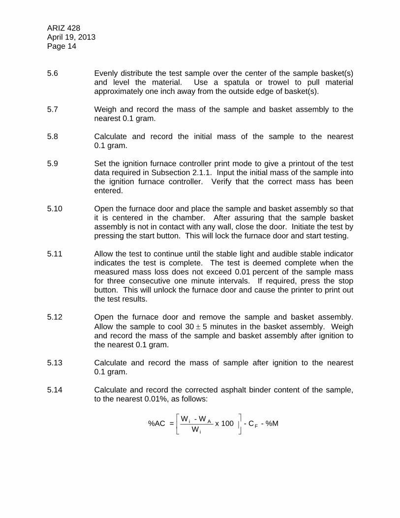
ARIZ 428 April 19, 2013 Page 14 5.6 Evenly distribute the test sample over the center of the sample basket(s)
and level the material. Use a spatula or trowel to pull material approximately one inch away from the outside edge of basket(s).
5.7 Weigh and record the mass of the sample and basket assembly to the
nearest 0.1 gram. 5.8 Calculate and record the initial mass of the sample to the nearest
0.1 gram. 5.9 Set the ignition furnace controller print mode to give a printout of the test
data required in Subsection 2.1.1. Input the initial mass of the sample into the ignition furnace controller. Verify that the correct mass has been entered.
5.10 Open the furnace door and place the sample and basket assembly so that
it is centered in the chamber. After assuring that the sample basket assembly is not in contact with any wall, close the door. Initiate the test by pressing the start button. This will lock the furnace door and start testing.
5.11 Allow the test to continue until the stable light and audible stable indicator
indicates the test is complete. The test is deemed complete when the measured mass loss does not exceed 0.01 percent of the sample mass for three consecutive one minute intervals. If required, press the stop button. This will unlock the furnace door and cause the printer to print out the test results.
5.12 Open the furnace door and remove the sample and basket assembly.
Allow the sample to cool 30 5 minutes in the basket assembly. Weigh and record the mass of the sample and basket assembly after ignition to the nearest 0.1 gram.
5.13 Calculate and record the mass of sample after ignition to the nearest
0.1 gram. 5.14 Calculate and record the corrected asphalt binder content of the sample,
to the nearest 0.01%, as follows:
%M - C - 100 x W
WW = %AC F
i
A i
-
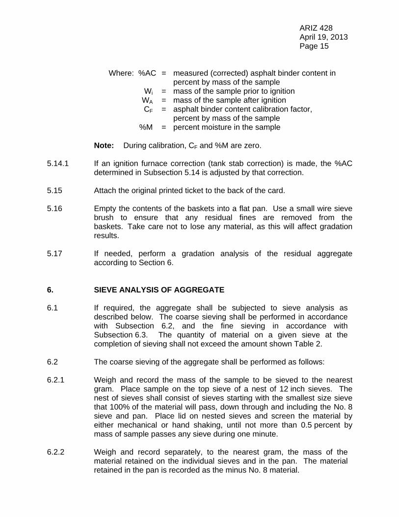
ARIZ 428 April 19, 2013 Page 15
Where: %AC = measured (corrected) asphalt binder content in percent by mass of the sample
Wi = mass of the sample prior to ignition WA = mass of the sample after ignition CF = asphalt binder content calibration factor, percent by mass of the sample %M = percent moisture in the sample
Note: During calibration, CF and %M are zero.
5.14.1 If an ignition furnace correction (tank stab correction) is made, the %AC
determined in Subsection 5.14 is adjusted by that correction. 5.15 Attach the original printed ticket to the back of the card. 5.16 Empty the contents of the baskets into a flat pan. Use a small wire sieve
brush to ensure that any residual fines are removed from the baskets. Take care not to lose any material, as this will affect gradation results.
5.17 If needed, perform a gradation analysis of the residual aggregate
according to Section 6. 6. SIEVE ANALYSIS OF AGGREGATE 6.1 If required, the aggregate shall be subjected to sieve analysis as
described below. The coarse sieving shall be performed in accordance with Subsection 6.2, and the fine sieving in accordance with Subsection 6.3. The quantity of material on a given sieve at the completion of sieving shall not exceed the amount shown Table 2.
6.2 The coarse sieving of the aggregate shall be performed as follows: 6.2.1 Weigh and record the mass of the sample to be sieved to the nearest
gram. Place sample on the top sieve of a nest of 12 inch sieves. The nest of sieves shall consist of sieves starting with the smallest size sieve that 100% of the material will pass, down through and including the No. 8 sieve and pan. Place lid on nested sieves and screen the material by either mechanical or hand shaking, until not more than 0.5 percent by mass of sample passes any sieve during one minute.
6.2.2 Weigh and record separately, to the nearest gram, the mass of the
material retained on the individual sieves and in the pan. The material retained in the pan is recorded as the minus No. 8 material.

ARIZ 428 April 19, 2013 Page 16
TABLE 2
Maximum Mass Allowed (grams) Sieve
Size
Maximum Mass Allowed (grams/sq. in.) 8 inch
Diameter Sieve
12 inch Diameter
Sieve 1-1/2” 25 --- 2827
1” 18 --- 2036 3/4” 14 --- 1583 1/2” 10 --- 1131 3/8” 8 --- 905 1/4” 6 --- 679
No. 4 5 --- 565 No. 8 and smaller 4 201 452
6.2.3 Do not discard any of the sieved material until the sum of the individual
masses is compared to the mass of the sample prior to sieving. If the difference between the two masses is less than or equal to 1.0% of the mass of the sample prior to sieving, an adjustment in mass shall be made on the sieve which has the largest mass retained, except no adjustment shall be made on the minus No. 8 material. If the difference is greater than 1.0%, the sample shall be recombined, resieved, and carefully reweighed.
6.2.4 Determine the coarse sieve factor by dividing 100 by the total mass
sieved. Record the factor to six decimal places. 6.2.5 The percent passing for each sieve in the coarse sieve analysis is
determined by multiplying the mass retained on that sieve by the coarse sieve factor, and subtracting the result from the unrounded % passing for the next larger sieve. Values for "mass retained multiplied by the coarse sieve factor" and "percent passing each sieve" shall be determined and used in the calculations to six decimal places. The percent passing value for each sieve is recorded in the sieve analysis to the nearest percent.
6.2.6 As a check on the coarse sieve analysis, multiply the mass of minus No. 8
material by the coarse sieve factor. The result of this calculation, rounded to the nearest percent, should be the same as the value for percent passing the No. 8 sieve determined in Subsection 6.2.5 above.

ARIZ 428 April 19, 2013 Page 17 6.2.7 The material passing the No. 8 sieve is split, if necessary, to obtain a
minimum 500 gram sample for fine fine sieving; however, the sample size may be less than 500 grams if a minimum of 500 grams is not obtained from coarse sieving. If less than 800 grams passes the No. 8 sieve, the entire amount shall be subjected to fine sieving. The mass of the sample for fine sieving is recorded to the nearest gram as mass of pass No. 8 split.
6.3 The elutriation and fine sieving of the pass No. 8 material shall be
performed as follows: 6.3.1 Subject sample to elutriation through a No. 200 screen either by hand or
mechanical washing. 6.3.2 Dry sample to constant mass, allow to cool, then weigh and record the
dry mass to the nearest gram. 6.3.3 Place sample on the top sieve of a nest of fine sieves. The nest of
sieves shall consist of sieves starting with the No. 10 sieve, down through and including the No. 200 sieve and pan. Place lid on nested sieves and screen the material by either mechanical or hand shaking, until not more than 0.5 percent by mass of sample passes any sieve during one minute.
6.3.4 Weigh and record separately, to the nearest gram, the mass of material
retained on the individual sieves and in the pan. 6.3.5 Do not discard any of the sieved material until the sum of the individual
masses is compared to the mass of the sample prior to sieving. If the difference between the two masses is less than or equal to 1.0% of the mass of the sample prior to sieving, an adjustment in mass shall be made on the sieve which has the largest mass retained, except no adjustment shall be made on the minus No. 200 material. If the difference is greater than 1.0%, the sample shall be recombined, resieved, and carefully reweighed.
6.3.6 Determine and record elutriation to nearest gram by determining the
difference between the dry mass and the mass of the pass No. 8 split. 6.3.7 Determine a factor for calculating the fine sieve analysis by dividing the
percent passing the No. 8 sieve (recorded to the nearest percent) by the mass of pass No. 8 split. Record the factor to six decimal places. If all the pass No. 8 material from coarse sieving was subjected to elutriation and fine sieving, a fine sieve factor is not determined. Rather, the coarse
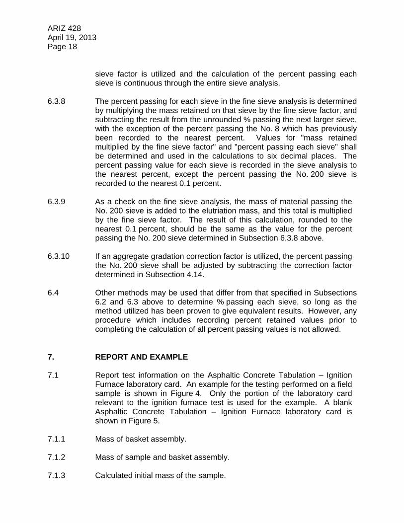
ARIZ 428 April 19, 2013 Page 18
sieve factor is utilized and the calculation of the percent passing each sieve is continuous through the entire sieve analysis.
6.3.8 The percent passing for each sieve in the fine sieve analysis is determined
by multiplying the mass retained on that sieve by the fine sieve factor, and subtracting the result from the unrounded % passing the next larger sieve, with the exception of the percent passing the No. 8 which has previously been recorded to the nearest percent. Values for "mass retained multiplied by the fine sieve factor" and "percent passing each sieve" shall be determined and used in the calculations to six decimal places. The percent passing value for each sieve is recorded in the sieve analysis to the nearest percent, except the percent passing the No. 200 sieve is recorded to the nearest 0.1 percent.
6.3.9 As a check on the fine sieve analysis, the mass of material passing the
No. 200 sieve is added to the elutriation mass, and this total is multiplied by the fine sieve factor. The result of this calculation, rounded to the nearest 0.1 percent, should be the same as the value for the percent passing the No. 200 sieve determined in Subsection 6.3.8 above.
6.3.10 If an aggregate gradation correction factor is utilized, the percent passing
the No. 200 sieve shall be adjusted by subtracting the correction factor determined in Subsection 4.14.
6.4 Other methods may be used that differ from that specified in Subsections
6.2 and 6.3 above to determine % passing each sieve, so long as the method utilized has been proven to give equivalent results. However, any procedure which includes recording percent retained values prior to completing the calculation of all percent passing values is not allowed.
7. REPORT AND EXAMPLE 7.1 Report test information on the Asphaltic Concrete Tabulation – Ignition
Furnace laboratory card. An example for the testing performed on a field sample is shown in Figure 4. Only the portion of the laboratory card relevant to the ignition furnace test is used for the example. A blank Asphaltic Concrete Tabulation – Ignition Furnace laboratory card is shown in Figure 5.
7.1.1 Mass of basket assembly. 7.1.2 Mass of sample and basket assembly. 7.1.3 Calculated initial mass of the sample.

ARIZ 428 April 19, 2013 Page 19 7.1.4 Mass of sample and basket assembly after ignition. 7.1.5 Calculated mass of sample after ignition. 7.1.6 Asphalt binder content calibration factor. 7.1.7 Percent moisture from moisture test, if one was performed. 7.1.8 Corrected percent asphalt binder content. 7.1.9 Elapsed time of test. 7.1.10 Name of the operator. 7.1.11 Sample test date. 7.1.12 Design percent asphalt binder content. 7.1.13 Ignition furnace set temperature. 7.1.14 If determined, the sieve analysis of the residual aggregate (corrected for
passing the No. 200 sieve if applicable).

ARIZ 428 April 19, 2013 Page 20
FIGURE 1

ARIZ 428 April 19, 2013 Page 21
FIGURE 2
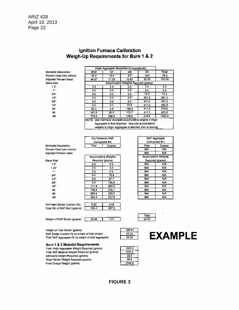
ARIZ 428 April 19, 2013 Page 22
FIGURE 3

ARIZ 428 April 19, 2013 Page 23
FIGURE 4

ARIZ 428 April 19, 2013 Page 24
FIGURE 5

ARIZ 428 April 19, 2013 Page 25
APPENDIX A
DETERMINATION OF GRADATION, MOISTURE CONTENT, AND BINDER CONTENT OF THE RAP MATERIAL
A.1 Obtain a representative sample of the RAP material in accordance with
Arizona Test Method 105. When multiple RAP stockpiles are used, a separate representative sample shall be obtained from each stockpile.
A.1.1 The sample shall be split to provide a sufficient amount of material for
gradation testing, moisture content testing, and binder content testing. A.2 The entire split sample of RAP material from each stockpile is dried at
140 F and the percent moisture content determined as described below.
Note: A higher drying temperature is not appropriate because it will soften the binder causing the RAP material to break into smaller particles and adhere to the drying pan.
A.2.1 The weight of the RAP material from each stockpile is determined and
recorded to the nearest 0.1 gram. A.2.2 The material is dried to constant weight at 140 10 F.
Note: Drying to constant weight at 140 F will typically take overnight.
A.2.3 After drying to constant weigtht at 140 10 F, cover the material and
allow to cool 30 10 minutes at room temperature. The weight of the RAP material is then determined and recorded to the nearest 0.1 gram.
A.2.4 The percent moisture content of the RAP material from each stockpile is
determined and recorded to the nearest 0.01 percent by the following:
100 x
Drying After
Material of Weight
Drying After
Material of Weight -
Drying to Prior
Material of Weight
Content
Moisture Percent

ARIZ 428 April 19, 2013 Page 26 A.3 After drying and determining the moisture content at 140 °F, the RAP
material shall be tested for gradation, moisture content (at 290 F), and binder content.
A.3.1 The gradation of the RAP material from each stockpile shall be
determined as described below. A.3.1.1 Split out a representative sample of the RAP material from each stockpile
which conforms to the size specified in Table 3.
TABLE 3
Maximum Size of Particle (See Note)
Minimum Weight of Sample, grams
3/4 in. and larger 5000 1/2 in. 2000 3/8 in. 1000
Note: The smallest sieve opening through which the entire amount of material will pass.
A.3.1.2 Dry sieve the material in accordance with Arizona Test Method 240, with
the exception that the No. 8 sieve shall be used as the smallest sieve. (Arizona Test Method 240 limits the time for shaking the sample to 5 minutes 15 seconds to control breakdown of the particles of RAP material into smaller size fractions.) The gradation of the RAP material from each stockpile is then determined in accordance with Arizona Test Method 248, Alternate #2.
A.3.2 The percent moisture content of the RAP material from each stockpile
shall be determined by drying at 290 F as described below.
Note: The sample for determining the moisture content at 290 F shall be obtained at the same time and subjected to the same treatment prior to testing as the sample obtained for determining the RAP binder content.
A.3.2.1 Split out a representative 1000 50 gram sample of the RAP material
from each stockpile. The weight of each sample is determined and recorded to the nearest 0.1 gram.
A.3.2.2 Each sample is dried at 290 10 F to constant weight. Constant weight
is defined as the weight at which further drying does not alter the weight more than 0.1 gram at intervals of a minimum of 30 minutes.

ARIZ 428 April 19, 2013 Page 27 A.3.2.3 After drying to constant weight at 290 10 F, cover the sample and allow
to cool 30 10 minutes at room temperature. The weight of the sample is then determined and recorded to the nearest 0.1 gram.
A.3.2.4 The percent moisture content of the RAP material from each stockpile is
determined and recorded to the nearest 0.01 percent by the following:
100 x
Drying to Prior
Material of Weight
Drying After
Material of Weight -
Drying to Prior
Material of Weight
Content
Moisture Percent
A.3.3 The total percent moisture content of the RAP material from each
stockpile is determined by adding the percent moisture content by drying at 140 F (Subsection A.2) to the percent moisture content by drying at 290 F (Subsection A.3.2).
A.3.4 The binder content of the RAP material from each stockpile shall be
determined as described below. A.3.4.1 Split out a representative sample of the RAP material from each stockpile
which conforms to the size specified in Table 4.
TABLE 4
Nominal Maximum RAP Aggregate Size (See Notes)
Mass of Sample, grams
1 in. 2500 – 3000 3/4 in. 2000 – 2500 1/2 in. 1500 – 2000 3/8 in. 1200 – 1700 No. 4 1200 – 1700
Note: The nominal maximum RAP aggregate size is defined as: One size larger than the first sieve that retains more than 10 percent RAP aggregate. Note: To determine the nominal maximum RAP aggregate size, the RAP aggregate gradation of each RAP stockpile, as shown in the mix design or as detemined from previous testing, may provide information.

ARIZ 428 April 19, 2013 Page 28 A.3.4.2 Preheat the ignition furnace to 538 5 C (1000 9 F). Do not preheat
the sample basket. A.3.4.3 Weigh and record the mass of the basket assembly to the nearest
0.1 gram. A.3.4.4 Perform ignition furnace testing on the RAP material from each stockpile
in accordance with Subsections 5.6 through 5.13. A.3.4.5 Calculate and record the binder content of the material from each RAP
stockpile, to the nearest 0.01%, as follows:
%M - 100 x W
WW = %AC
i
A i
-
Where: %AC = measured RAP binder content in percent by mass of the sample
Wi = mass of the sample prior to ignition WA = mass of the sample after ignition %M = percent moisture in the sample (determined by drying at 290 F, per Subsection A.3.2)
A.3.4.5.1 Retain the original printed ticket and save with other test documentation. A.3.4.6 Each measured binder content test result, as determined in Subsection
A.3.4.5, is adjusted by the appropriate RAP binder content correction factor (See Appendix B). This adjustment is made by adding the RAP binder correction factor to each measured binder content. The corrected RAP binder content is recorded to the nearest 0.01%.
A.4 If needed, determine the RAP aggregate gradation by performing a sieve
analysis of the residual aggregate in accordance with Section 6.
Note: Subsection 6.3.10 does not apply when determining the RAP aggregate gradation.
A.5 Report test information on the “RAP Material Tabulation - Ignition
Furnace” laboratory card. An example is shown in Figure 6. A blank “RAP Material Tabulation - Ignition Furnace” laboratory card is shown in Figure 7.

ARIZ 428 April 19, 2013 Page 29
FIGURE 6

ARIZ 428 April 19, 2013 Page 30
FIGURE 7

ARIZ 428 April 19, 2013 Page 31
APPENDIX B
DETERMINATION OF THE RAP BINDER CORRECTION FACTOR B.1 A RAP binder content correction factor is determined for each RAP
stockpile used in the asphaltic concrete mixture. B.2 At the start of asphaltic concrete production, the first two samples of RAP
material from each stockpile are split and tested for asphalt binder content; one split is tested by ignition furnace as described in Subsections A.3.4.2 through A.3.4.5.1, and the other split is tested by solvent extraction in accordance with AASHTO T 164. Note: Generally, 9000 grams of RAP material from each stockpile
will be adequate to obtain the split samples for determining the RAP binder content correction factor.
Note: At the discretion of the Engineer, the RAP binder correction
factor may be determined prior to the start of asphaltic concrete production provided representative RAP samples are available.
B.3 The average asphalt binder content determined by ignition furnace is
recorded to the nearest 0.001%. B.4 The average asphalt binder content determined by solvent extraction is
recorded to the nearest 0.001%. B.5 The RAP binder content correction factor is determined by subtracting the
average ignition furnace result from the average solvent extraction result. The RAP binder content correction factor is recorded to the nearest 0.01%.
B.6 A new RAP binder correction factor may be determined at any time the
Engineer believes it is necessary due to a change in material or other circumstances.
B.7 Report the determination of the RAP binder content correction factor on
the “RAP Binder Content Correction Factor” laboratory card. An example is shown in Figure 8. A blank “RAP Binder Content Correction Factor” laboratory card is shown in Figure 9.

ARIZ 428 April 19, 2013 Page 32
FIGURE 8
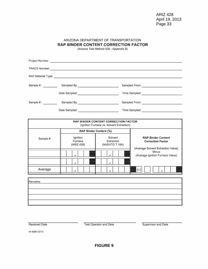
ARIZ 428 April 19, 2013 Page 33
FIGURE 9


ARIZ 732a April 19, 2013 (3 Pages)
CALCIUM CARBONATE IN TOPSOIL (NEUTRALIZATION POTENTIAL OF TOPSOIL)
(An Arizona Method)
1. SCOPE 1.1 This test method is used to determine the acid-consumption capacity or
alkalinity of a topsoil as defined by the conditions of the test itself. The principal mineral components of the topsoil which give rise to this alkalinity are generally taken to be alkali and alkaline earth metal carbonates. They are represented by calcium carbonate, the most abundant member of the group.
1.2 A large excess of Hydrochloric Acid Standard Solution is added to ensure
complete decomposition of the Calcium Carbonate. Then, the residual acid is backtitrated out with Sodium Hydroxide Standard Solution.
1.3 This test method involves hazardous material, operations, or
equipment. This test method does not purport to address all of the safety concerns associated with its use. It is the responsibility of the user to consult and establish appropriate safety and health practices and determine the applicability of any regulatory limitations prior to use.
1.4 See Appendix A1 of the Materials Testing Manual for information
regarding the procedure to be used for rounding numbers to the required degree of accuracy.
2. APPARATUS 2.1 Requirements for the frequency of equipment calibration and verification
are found in Appendix A3 of the Materials Testing Manual. Apparatus for this test procedure shall consist of the following:
2.1.1 25 mL, volumetric pipette, accurate to 0.05 mL. 2.1.2 A balance or scale capable of measuring the maximum weight to be
determined and conforming to the requirements of AASHTO M 231, except the readability and sensitivity of any balance or scale utilized shall be at least 0.01 gram.

ARIZ 732a April 19, 2013 Page 2 2.1.3 Filter paper equivalent to Whatman No. 40. 2.1.4 Filtration funnel, 7.5 cm, 60, long stem. 2.1.5 300 mL beaker, tall form, graduated. 2.1.6 25 mL burette, accurate to 0.01 mL. 2.1.7 Stirring rod (glass or plastic). 3. REAGENTS 3.1 1.00 0.10 Normal Hydrochloric Acid Standard Solution. Label this
solution “Reagent 1” or “R1” on the bottle. This reagent is available from laboratory chemical suppliers as a standardized solution. Its normality should be checked regularly against “Reagent 2” below, as required by frequency of use. Record the actual normality of this solution as “N1”.
3.2 1.00 0.10 Normal Sodium Hydroxide Standard Solution. Label this
solution “Reagent 2” or “R2” on the bottle. This reagent is available from laboratory chemical suppliers as a standardized solution. Its normality should be checked regularly against primary standard Potassium Biphthalate, as required by frequency of use. Record the actual normality of this solution as “N2”.
3.3 Phenolphthalein Indicator (1% Phenolphthalein in 50% Isopropyl Alcohol). 3.4 Demineralized Water. 4. PROCEDURE 4.1 Weigh 1.00 0.01 gram of soil passing a No. 12 sieve into a 300 mL
beaker. 4.2 Pipette 25.00 0.05 mL Hydrochloric Acid Solution (Reagent 1) into the
300 mL beaker. 4.3 Stir thoroughly with a stirring rod. 4.4 Let the mixture stand undisturbed for 15 minutes, or, if significant bubbling
is observed, 30 minutes.

ARIZ 732a April 19, 2013 Page 3 4.5 Filter the entire contents of the 300 mL beaker into another 300 mL beaker
and rinse three times with demineralized water, being careful to keep the total volume at or under 100 mL.
4.6 Dilute to 100 mL, if necessary, with demineralized water, and add one
drop of Phenolphthalein Indicator. 4.7 Backtitrate the residual Hydrochloric Acid with Sodium Hydroxide Solution
(Reagent 2) to a Phenolphthalein endpoint. 4.8 Record the volume of Reagent 2 delivered, to the nearest 0.05 mL,
as “V2”. 5. CALCULATIONS AND REPORT 5.1 Calculate Calcium Carbonate, in percent, using the following formula:
1N x
1N
2
x V2
N - 25 x 5 % Carbonate, Calcium
5.2 Report Calcium Carbonate to the nearest 0.1%.


ARIZ 743 April 19, 2013 (4 Pages)
TITANIUM DIOXIDE IN PAINTS AND THERMOPLASTICS
(An Arizona Method)
1. SCOPE 1.1 This test method may be used to make a rapid estimation of the amount of
Titanium Dioxide pigment in paints and thermoplastics, particularly those of white color used for traffic control markings.
1.2 The method is a non-instrumental, gravimetric method, which involves
removing, successively, all accompanying constituents of the material, leaving only the Titanium Dioxide analyte. The isolated analyte is weighed directly.
1.3 The method is applicable for paints and for thermoplastics, with or without
glass beads. 1.4 The procedure in this method consists of two parts. Part A is for
paints; Part B is for thermoplastics. 1.5 This test method involves hazardous material, operations, or
equipment. This test method does not purport to address all of the safety concerns associated with its use. It is the responsibility of the user to consult and establish appropriate safety and health practices and determine the applicability of any regulatory limitations prior to use.
1.6 See Appendix A1 of the Materials Testing Manual for information
regarding the procedure to be used for rounding numbers to the required degree of accuracy.
2. APPARATUS 2.1 Requirements for the frequency of equipment calibration and verification
are found in Appendix A3 of the Materials Testing Manual. Apparatus for this test procedure shall consist of the following:
2.1.1 600 mL beaker, graduated.

ARIZ 743 April 19, 2013 Page 2 2.1.2 Whatman No. 40 ashless filter paper, 125 mm, or equivalent. 2.1.3 A balance or scale capable of measuring the maximum weight to be
determined and conforming to the requirements of AASHTO M 231, except that the readability and sensitivity of any balance or scale utilized shall be at least 0.0001 gram.
2.1.4 50 mL porcelain crucible. 2.1.5 Filtration funnel, 7.5 cm, 60, long stem. 2.1.6 Watch glass, 3 inch. 2.1.7 Glass stirring rod. 2.1.8 Muffle furnace, capable of maintaining a constant temperature of 450 C. 2.1.9 Drying oven, capable of maintaining a constant temperature of 110 C. 2.1.10 Dessicator. 2.1.11 Hot plate. 3. REAGENTS 3.1 Concentrated Hydrochloric Acid Solution. 3.2 Concentrated Nitric Acid Solution. 3.3 Demineralized water. 4. PROCEDURE 4.1 PART A (FOR PAINTS): 4.1.1 Weigh 5.0000 0.2500 grams of paint into a crucible. Record the weight
of the paint specimen as “B” to the nearest 0.0001 gram. 4.1.2 Place crucible and specimen into the drying oven at temperature of
110 C.

ARIZ 743 April 19, 2013 Page 3 4.1.3 After 2 hours, remove crucible, place into cold muffle furnace, and set the
temperature to 450 C. 4.1.4 Ignite specimen at 450 C for 1 hour after the temperature of 450 C is
attained. 4.1.5 Remove crucible with ignition residue and allow to cool to room
temperature. 4.1.6 Place crucible with residue into 300 mL beaker. 4.1.7 Cautiously, dropwise, add 30 mL Concentrated Hydrochloric Acid to
crucible. 4.1.8 Cautiously add 10 mL Concentrated Nitric Acid to crucible. 4.1.9 After digestion of the residue is complete, add 250 mL of demineralized
water to beaker, add 1 boiling chip, cover with watchglass, and place on the hot plate.
4.1.10 Heat beaker contents to boiling and boil for 15 minutes. 4.1.11 Remove beaker from hotplate and filter contents, carefully washing and
decanting titanium dioxide, leaving boiling chip and glass beads, if any, in the beaker. Wash thoroughly with demineralized water.
4.1.12 Tightly fold filter and place into tared crucible. Record crucible weight
as “A,” to the nearest 0.0001 gram. 4.1.13 Place crucible and contents into cold furnace and set temperature to
450 C. 4.1.14 Ignite specimen at 450 C for 1 hour after temperature of 450 C is
attained. 4.1.15 Remove crucible and allow to cool to room temperature in dessicator. 4.1.16 Weigh crucible and contents. Record weight as “C,” to the nearest 0.0001
gram.

ARIZ 743 April 19, 2013 Page 4 4.2 PART B (FOR THERMOPLASTICS):
4.2.1 Weigh 5.0000 0.2500 grams of thermoplastic into a crucible. Record the
weight of the thermoplastic specimen as “B” to the nearest 0.0001 gram.
4.2.2 Place crucible and specimen into cold muffle furnace and set the temperature to 450 C.
4.2.3 Proceed as specified in Subsections 4.1.4 through 4.1.16. 5. CALCULATIONS AND REPORT 5.1 Calculate Titanium Dioxide, in percent, using the following formula:
100 x B
A- C % Dioxide, itaniumT
5.2 Report Titanium Dioxide to the nearest 0.001%.

ARIZ 744 April 19, 2013 (3 Pages)
ROCK SALT IN CRASH BARREL SAND
(An Arizona Method)
1. SCOPE 1.1 This test method is used to determine the amount of rock salt which has
been mixed with sand for use in crash barrel cushions. 1.2 The method is a non-instrumental, gravimetric method, which involves
removing the salt from the sand/salt mixture by dissolution and washing away the salt using demineralized water. The salt content is then determined by weight loss after drying.
1.3 See Appendix A1 of the Materials Testing Manual for information
regarding the procedure to be used for rounding numbers to the required degree of accuracy.
2. APPARATUS 2.1 Requirements for the frequency of equipment calibration and verification
are found in Appendix A3 of the Materials Testing Manual. Apparatus for this test procedure shall consist of the following:
2.1.1 1000 mL heavy-duty glass beaker, graduated; KIMAX No. 14005, or
equivalent. 2.1.2 A balance or scale capable of measuring the maximum weight to be
determined and conforming to the requirements of AASHTO M 231, except that the readability and sensitivity of any balance or scale utilized shall be at least 0.1 gram.
2.1.3 Stirring rod (glass, steel, or plastic). 2.1.4 Drying oven, capable of maintaining a constant temperature of 110 C. 2.1.5 Spot plate (black).

ARIZ 744 April 19, 2013 Page 2 3. REAGENTS 3.1 Silver Nitrate Test Solution, 1%. Weigh approximately 0.5 gram of Silver
Nitrate crystals into a 100 mL beaker and dilute to 50 mL. Stir to dissolve, and transfer contents to an amber dropping bottle.
3.2 Demineralized water. 4. PROCEDURE 4.1 Weigh a clean beaker. Record the weight as “A” to the nearest 0.1 gram. 4.2 Weigh 500.0 5.0 grams of sand/salt mixture into the beaker. Record the
weight of the sand/salt mixture as “B” to the nearest 0.1 gram. 4.3 Add enough demineralized water to cover the specimen and fill the beaker
to the 750 mL mark. 4.4 Stir the contents of the beaker vigorously and let the mix stand for one
hour. 4.5 Decant and discard the supernatant extract solution. 4.6 Repeat Subsections 4.3 and 4.4, and then continue to Subsection 4.7. 4.7 Test two drops of the extract solution for the presence of chloride with two
drops of the silver nitrate solution, in the spot plate. 4.8 If the test indicates the presence of chloride (by a white cloudy solution),
repeat Subsections 4.3, 4.4, and 4.7. If the test indicates the absence of chloride, decant and discard the extract solution.
4.9 Place the beaker and wet sand residue into the drying oven. Dry
thoroughly at 110 C. 4.10 After drying, remove the beaker with dry sand residue from the oven and
allow to cool to room temperature. 4.11 Weigh the beaker and contents. Record the weight as “C” to the nearest
0.1 gram.

ARIZ 744 April 19, 2013 Page 3 5. CALCULATIONS AND REPORT 5.1 Calculate the salt content, in percent, using the following formula:
100 x B
C - B) (A % Salt,
5.2 Report as Percent Rock Salt, to the nearest 0.1%.