Embed Size (px)
Citation preview
Change in Failure Type when Wind Turbine Blades Scale-up
Sandia Wind Turbine Workshop 2012
Find Mølholt Jensen1, Alexander Kling2, John Dalsgaard Sørensen3
1Bladena (CTO and founder)2DLR (German Aerospace center)3Aalborg University and Technical University of Denmark
Together, we make your blade stronger1
Outline
Together, we make your blade stronger2
• Motivation
• Overview of failure modes which are expected to be design
driven for future blades
• How can these problems be addressed and solved in the
future?
• Example on how to find the root cause of failures
• Summary
Bladena in brief
Together, we make your blade stronger3
• Spin-out from Risø DTU – one of the leading
research instituts in wind energy
• Our mission is to empower designers,
manufacturers, service organisation and
owners to make their blades stronger
• Unique technological platform from a decade
of research and 7 founding patents.
• We will be bridging between the world class
research and competitive applied solutions.
Together, we make your blade stronger
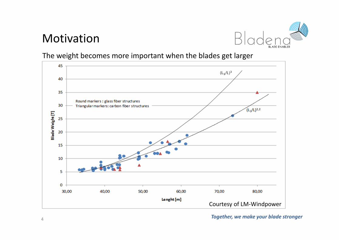
The weight becomes more important when the blades get larger
4
Motivation
Courtesy of LM-Windpower
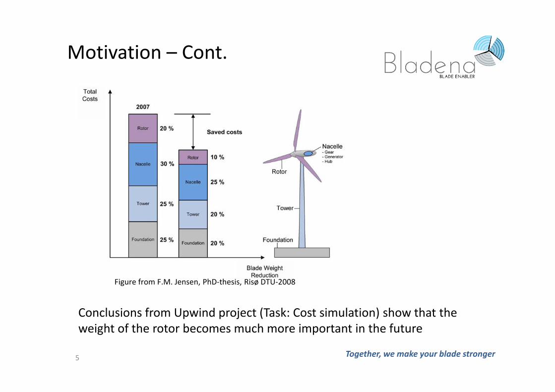
Conclusions from Upwind project (Task: Cost simulation) show that the
weight of the rotor becomes much more important in the future
Figure from F.M. Jensen, PhD-thesis, Risø DTU-2008
Motivation – Cont.
Together, we make your blade stronger5
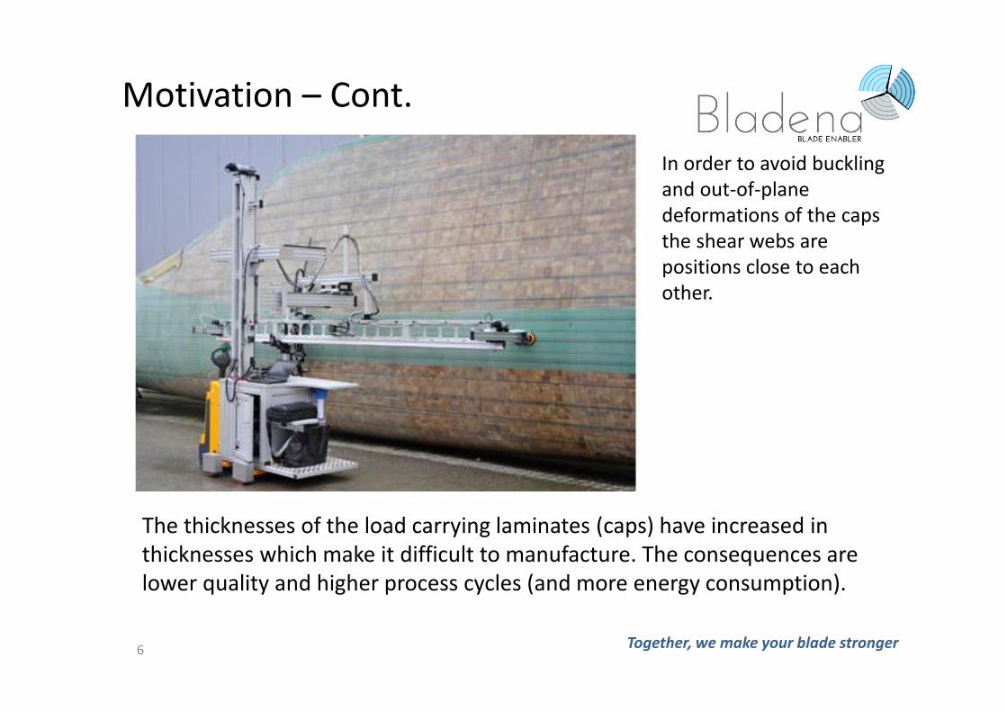
The thicknesses of the load carrying laminates (caps) have increased in
thicknesses which make it difficult to manufacture. The consequences are
lower quality and higher process cycles (and more energy consumption).
In order to avoid buckling
and out-of-plane
deformations of the caps
the shear webs are
positions close to each
other.
Motivation – Cont.
6 Together, we make your blade stronger
Together, we make your blade stronger
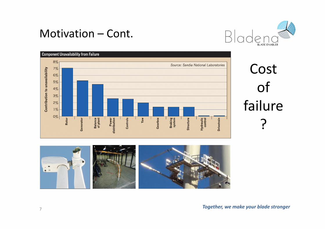
Motivation – Cont.
Cost
of
failure
?
7
Together, we make your blade stronger
The consequence of going offshore change the cost for repair and
replacement significantly.
Next generation of blade design are based on designs which still not have
proven to be reliable in operation over 20years.
In the past when blades were small the blades were mainly designed to be
aerodynamic optimal. Today, the consequence of having too thin
aerodynamic profiles result in heavier blades.
Tip deflection was a major design driver when the blades were small. Today
this do not drive the design in the way and there exist solutions which can
“compensate” for a too large tip deflections.
8
Shift in trends
Together, we make your blade stronger
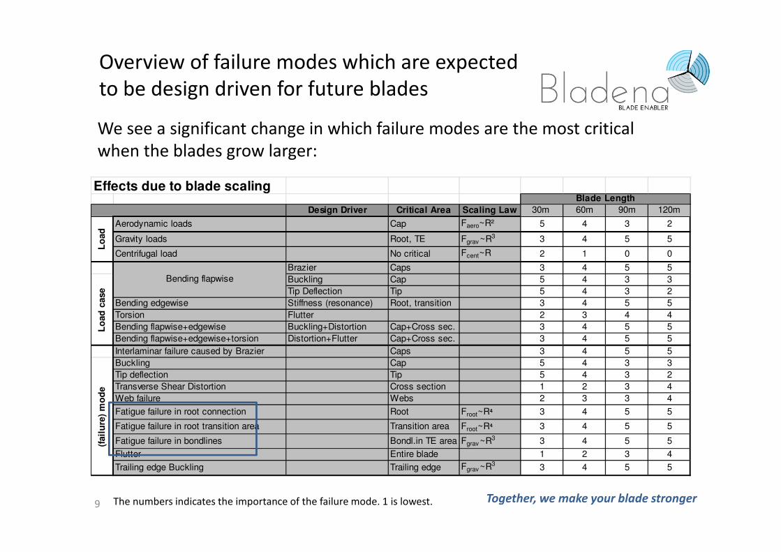
We see a significant change in which failure modes are the most critical
when the blades grow larger:
The numbers indicates the importance of the failure mode. 1 is lowest. 9
Overview of failure modes which are expected
to be design driven for future blades
Effects due to blade scaling
Design Driver Critical Area Scaling Law 30m 60m 90m 120m
Aerodynamic loads Cap Faero~R² 5 4 3 2
Gravity loads Root, TE Fgrav ~R3 3 4 5 5
Centrifugal load No critical Fcent~R 2 1 0 0
Brazier Caps 3 4 5 5
Buckling Cap 5 4 3 3
Tip Deflection Tip 5 4 3 2
Bending edgewise Stiffness (resonance) Root, transition 3 4 5 5
Torsion Flutter 2 3 4 4
Bending flapwise+edgewise Buckling+Distortion Cap+Cross sec. 3 4 5 5
Bending flapwise+edgewise+torsion Distortion+Flutter Cap+Cross sec. 3 4 5 5
Interlaminar failure caused by Brazier Caps 3 4 5 5
Buckling Cap 5 4 3 3
Tip deflection Tip 5 4 3 2
Transverse Shear Distortion Cross section 1 2 3 4
Web failure Webs 2 3 3 4
Fatigue failure in root connection Root Froot~R⁴ 3 4 5 5
Fatigue failure in root transition area Transition area Froot~R⁴ 3 4 5 5
Fatigue failure in bondlines Bondl.in TE area Fgrav ~R3 3 4 5 5
Flutter Entire blade 1 2 3 4
Trailing edge Buckling Trailing edge Fgrav ~R33 4 5 5
Blade Length
Lo
ad
case
Bending flapwise
Lo
ad
(fail
ure
) m
od
e
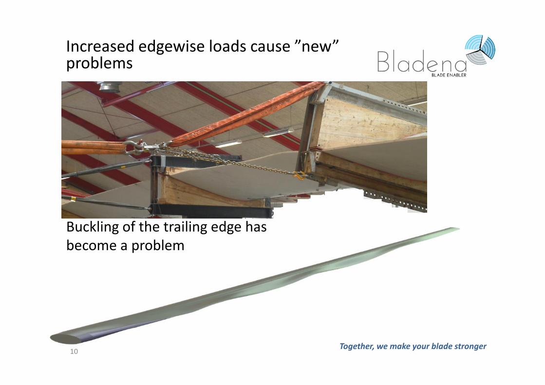
Buckling of the trailing edge has
become a problem
Increased edgewise loads cause ”new” problems
Together, we make your blade stronger 10
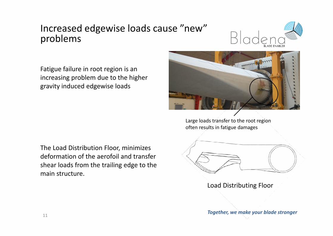
Fatigue failure in root region is an
increasing problem due to the higher
gravity induced edgewise loads
The Load Distribution Floor, minimizes
deformation of the aerofoil and transfer
shear loads from the trailing edge to the
main structure.
Large loads transfer to the root region
often results in fatigue damages
Increased edgewise loads cause ”new” problems
Together, we make your blade stronger 11
Load Distributing Floor
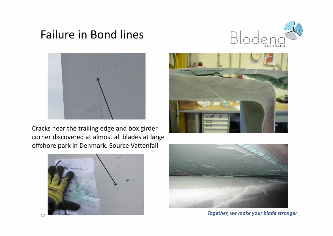
Cracks near the trailing edge and box girder
corner discovered at almost all blades at large
offshore park in Denmark. Source Vattenfall
12
Failure in Bond lines
Together, we make your blade stronger
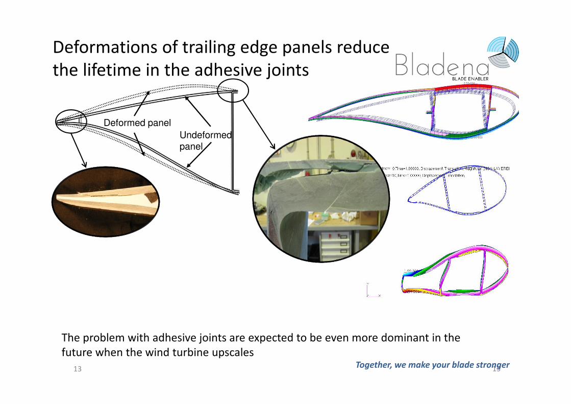
The problem with adhesive joints are expected to be even more dominant in the
future when the wind turbine upscales
Undeformed panel
Deformed panel
13
Deformations of trailing edge panels reduce
the lifetime in the adhesive joints
Together, we make your blade stronger13
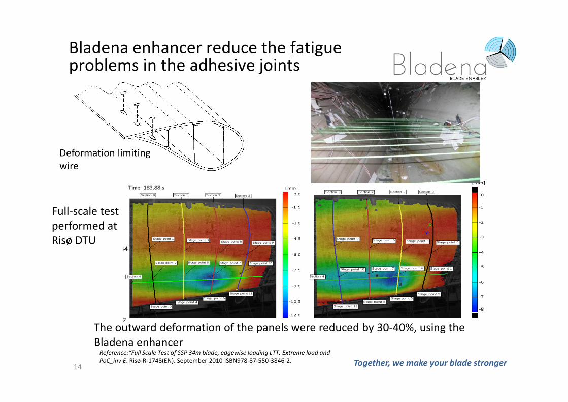
The outward deformation of the panels were reduced by 30-40%, using the
Bladena enhancer Reference:“Full Scale Test of SSP 34m blade, edgewise loading LTT. Extreme load and
PoC_inv E. Risø-R-1748(EN). September 2010 ISBN978-87-550-3846-2. Together, we make your blade stronger14
Bladena enhancer reduce the fatigue problems in the adhesive joints
Deformation limiting
wire
Full-scale test
performed at
Risø DTU
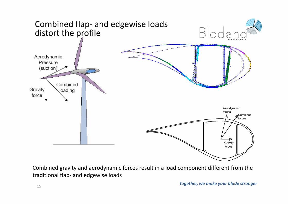
Combined gravity and aerodynamic forces result in a load component different from the
traditional flap- and edgewise loads
Combined flap- and edgewise loadsdistort the profile
Together, we make your blade stronger 15
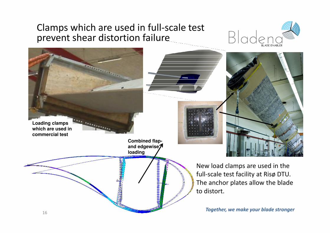
New load clamps are used in the
full-scale test facility at Risø DTU.
The anchor plates allow the blade
to distort.
Combined flap-
and edgewise
loading
Loading clamps
which are used in
commercial test
Clamps which are used in full-scale test prevent shear distortion failure
16Together, we make your blade stronger
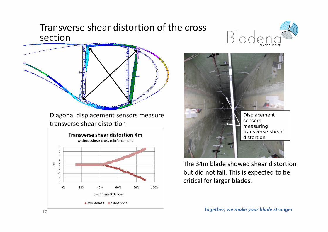
The 34m blade showed shear distortion
but did not fail. This is expected to be
critical for larger blades.
Diagonal displacement sensors measure
transverse shear distortion
Displacement sensors measuring transverse shear distortion
Transverse shear distortion of the crosssection
17 Together, we make your blade stronger
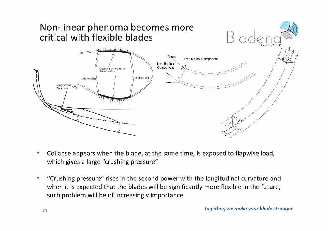
• Collapse appears when the blade, at the same time, is exposed to flapwise load,
which gives a large “crushing pressure”
• “Crushing pressure” rises in the second power with the longitudinal curvature and
when it is expected that the blades will be significantly more flexible in the future,
such problem will be of increasingly importance
Crushing pressure due to flexure bending
Trailing web Leading web
Non-linear phenoma becomes more critical with flexible blades
18 Together, we make your blade stronger
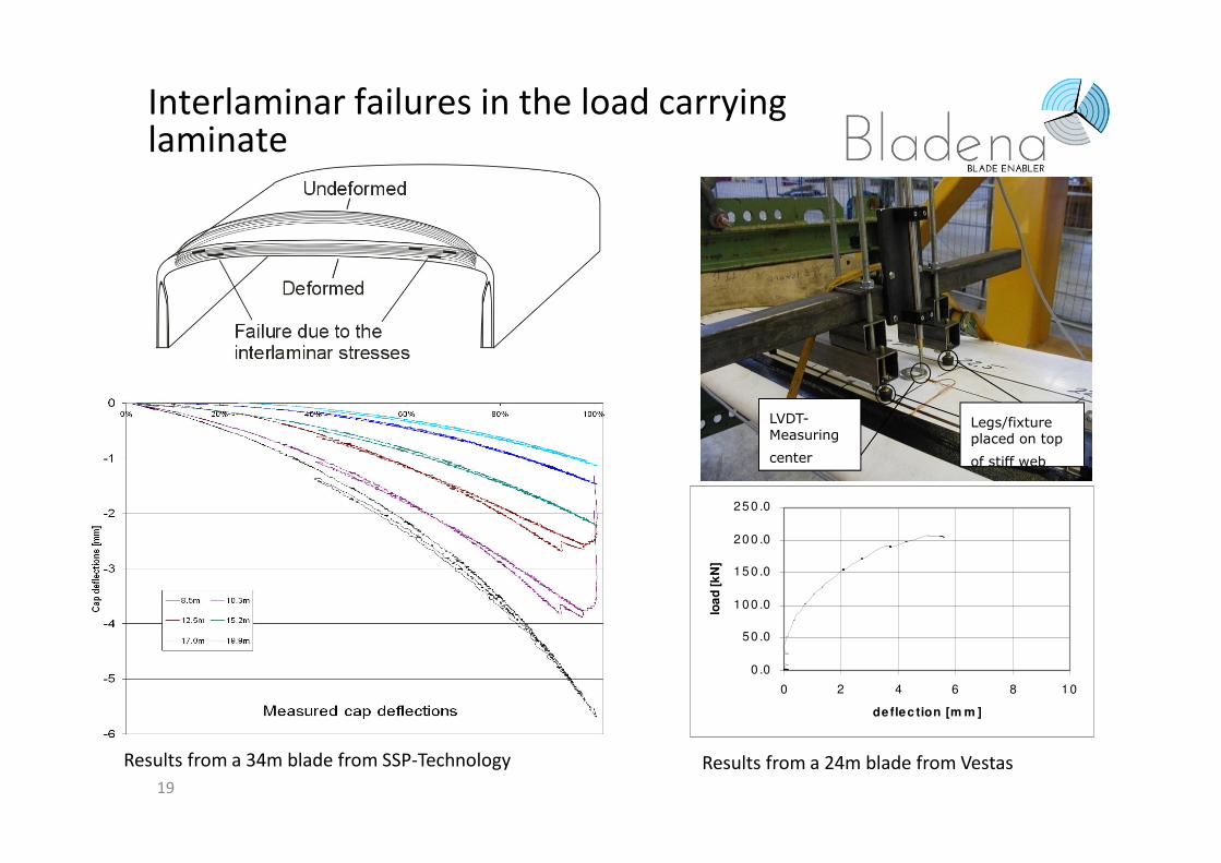
Legs/fixture placed on top
of stiff web
LVDT-Measuring
center
0 .0
50 .0
10 0 .0
15 0 .0
20 0 .0
25 0 .0
0 2 4 6 8 10
deflec tion [m m ]lo
ad
[k
N]
Results from a 34m blade from SSP-Technology Results from a 24m blade from Vestas
Interlaminar failures in the load carrying laminate
19
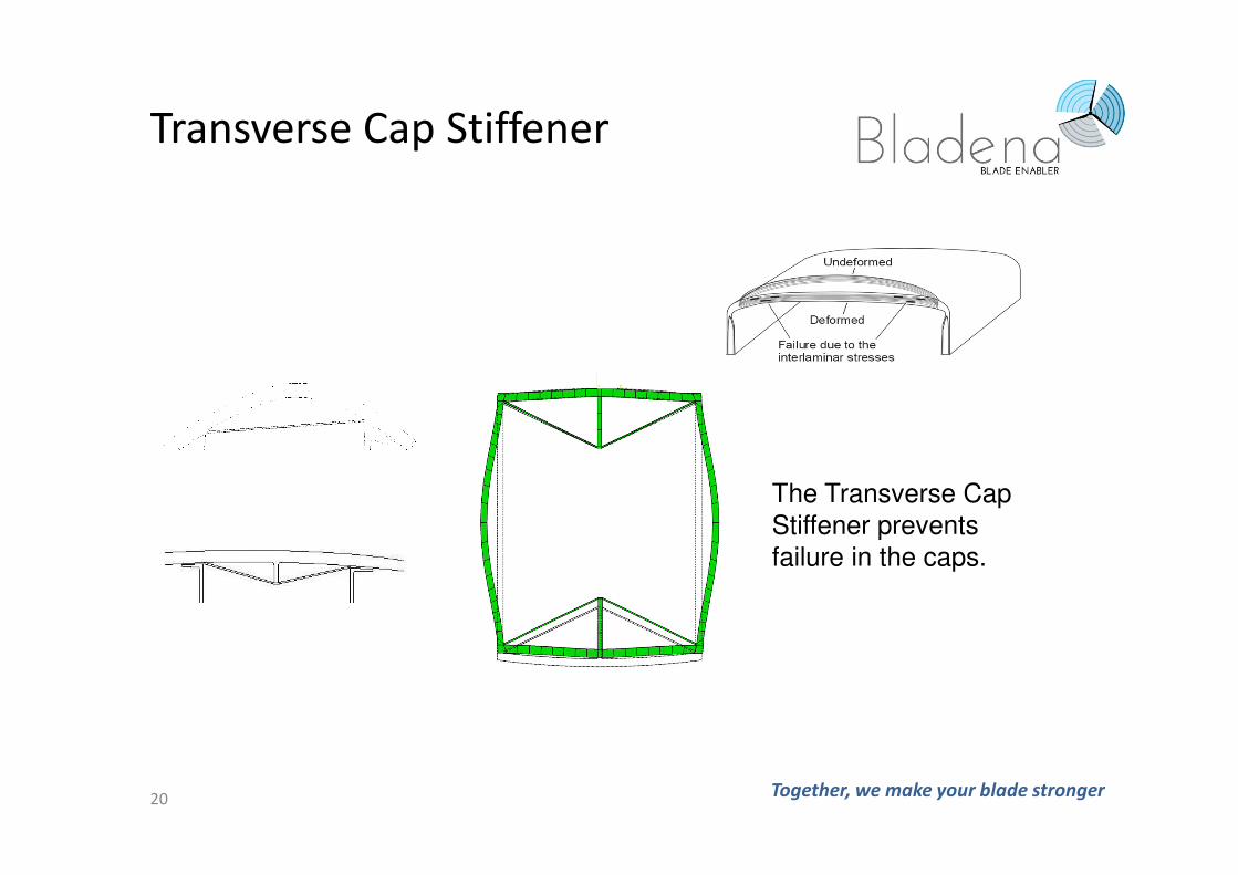
Transverse Cap Stiffener
Together, we make your blade stronger
The Transverse Cap
Stiffener prevents
failure in the caps.
20
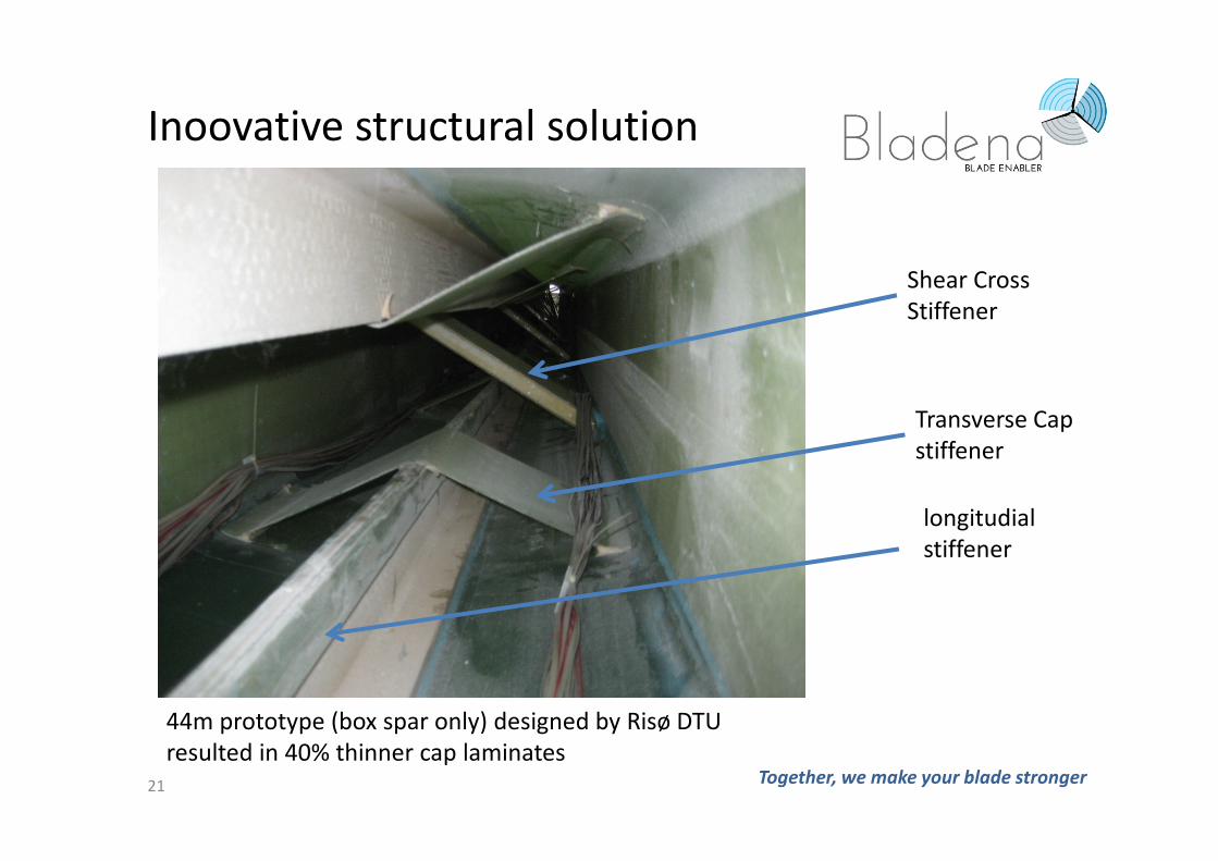
Inoovative structural solution
Together, we make your blade stronger
Shear Cross
Stiffener
Transverse Cap
stiffener
21
44m prototype (box spar only) designed by Risø DTU
resulted in 40% thinner cap laminates
longitudial
stiffener
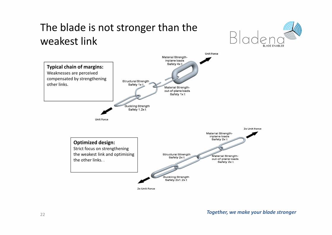
The blade is not stronger than the
weakest link
Together, we make your blade stronger
Typical chain of margins:Weaknesses are perceived
compensated by strengthening
other links.
Optimized design: Strict focus on strengthening
the weakest link and optimising
the other links. .
22
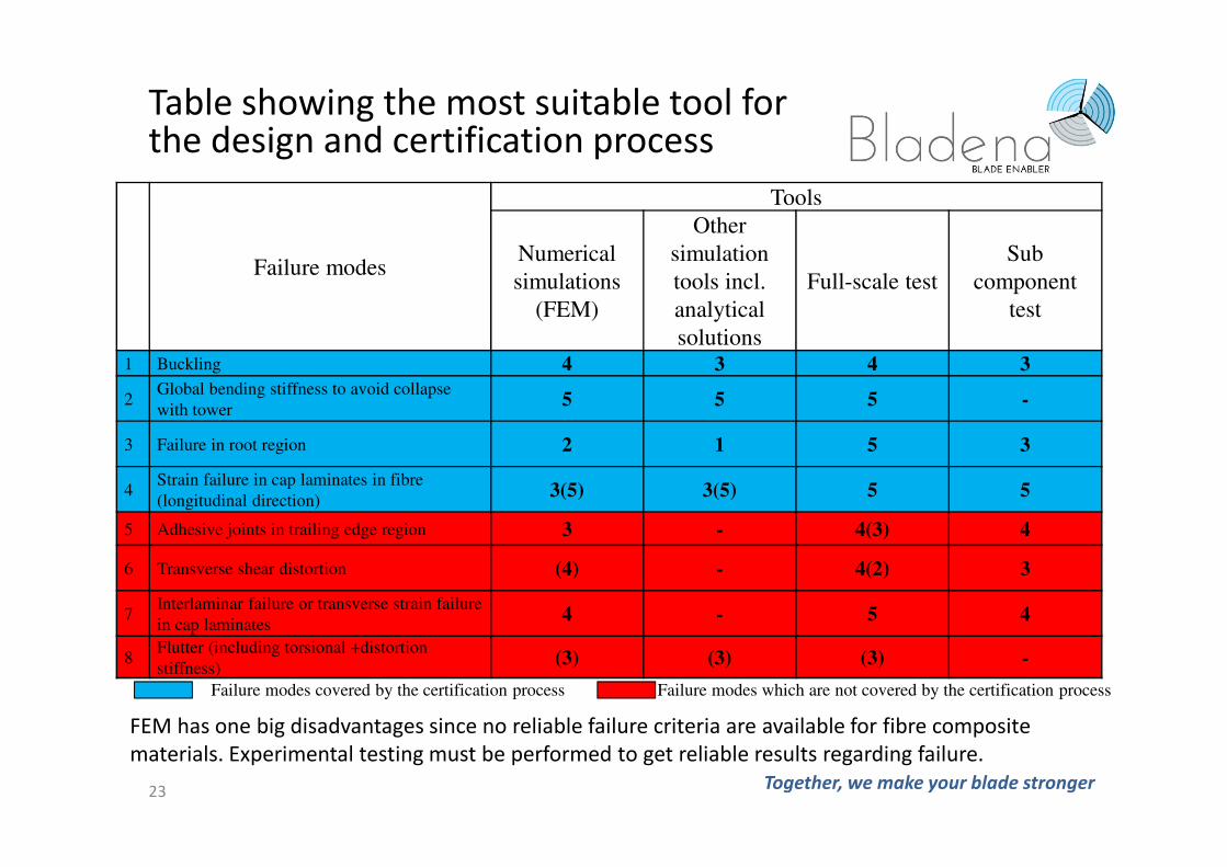
Failure modes
Tools
Numerical
simulations
(FEM)
Other
simulation
tools incl.
analytical
solutions
Full-scale test
Sub
component
test
1 Buckling 4 3 4 3
2Global bending stiffness to avoid collapse
with tower5 5 5 -
3 Failure in root region 2 1 5 3
4Strain failure in cap laminates in fibre
(longitudinal direction)3(5) 3(5) 5 5
5 Adhesive joints in trailing edge region 3 - 4(3) 4
6 Transverse shear distortion (4) - 4(2) 3
7Interlaminar failure or transverse strain failure
in cap laminates4 - 5 4
8Flutter (including torsional +distortion
stiffness)(3) (3) (3) -
Failure modes covered by the certification process Failure modes which are not covered by the certification process
FEM has one big disadvantages since no reliable failure criteria are available for fibre composite
materials. Experimental testing must be performed to get reliable results regarding failure.
Table showing the most suitable tool for the design and certification process
Together, we make your blade stronger23
Together, we make your blade stronger 24
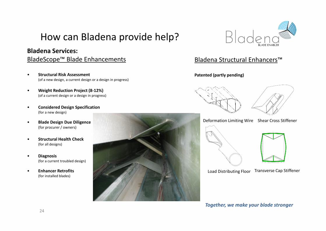
Bladena Services:
BladeScope™ Blade Enhancements
• Structural Risk Assessment(of a new design, a current design or a design in progress)
• Weight Reduction Project (8-12%)(of a current design or a design in progress)
• Considered Design Specification(for a new design)
• Blade Design Due Diligence (for procurer / owners)
• Structural Health Check (for all designs)
• Diagnosis(for a current troubled design)
• Enhancer Retrofits(for installed blades)
Bladena Structural Enhancers™
Patented (partly pending)
Transverse Cap Stiffener
Shear Cross StiffenerDeformation Limiting Wire
Load Distributing Floor
How can Bladena provide help?
Together, we make your blade stronger
Guide to Defects
An continuously updated guide supporting the inspector in writing an inspection report to make the
first and immediate categorization of the damages into damages and defects.
Defect Data Sheets
Detailed data sheets describing known defects including probable underlying failures and root causes,
risk profile, possible treatment solutions and next step recommendations.
Defect Report
Detailed report analyzing the defect and the possible underlying failures and root causes, and
producing a specific next step recommendation, either recommendation for repair, retrofit,
refurbishment or replacement, or diagnosis.
Diagnosis
Plan based on prioritized step for diagnosing the defects and identifying the underlying failure and root
causes. Included budget, partners and time line. Bladena can also support the actual diagnosis and
prepare a failure report with the found conclusions and treatment options.
25
Services offered via Service Partners
Together, we make your blade stronger
A service company has been asked to inspect some blades on a wind park
where blades has suffered damage.
Based on traditional approach the observation made by the service
company would have led to the repair of the surface coating, the only
“visible” sign of the underlying problem.
Bladena offers , through a service partner, a systematic approach on how to
identify the root cause of key issues seen on blades in service, and suggests
solutions aimed at reducing the impact of the problem in order to increase
the residual life of the damaged blades.
26
Inspections
Together, we make your blade stronger
1) The service partner find damages on a blade.
2) The damage may be “recognized” to be one of the failure types
addressed in this presentation, or another known defect. This is done
by using standard defect data sheets. The data sheets include a list of
root causes and some guidance on what needs to be done.
3) If one or more of the failures that are addressed may be related to
structural causes, a “defect report” is suggested.
4) In this “defect report”, Bladena analyze the available results including
the load history and failure type in more detail. The analysis will
probably help in excluding some root causes. Other will become more
relevant a more likely to be the source of the problem.
5) The few root causes remaining will be further analyzed in a “diagnostic
plan”. In this plan, a proposal on how the problem can be solved is
presented.
27
The analysis process
Together, we make your blade stronger
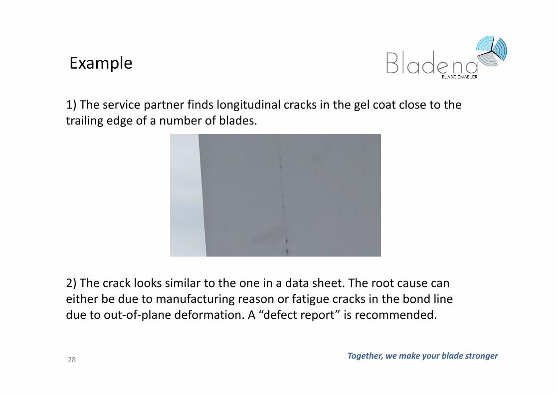
1) The service partner finds longitudinal cracks in the gel coat close to the
trailing edge of a number of blades.
28
Example
2) The crack looks similar to the one in a data sheet. The root cause can
either be due to manufacturing reason or fatigue cracks in the bond line
due to out-of-plane deformation. A “defect report” is recommended.
Together, we make your blade stronger
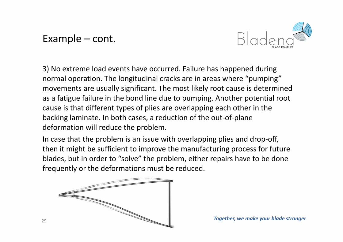
3) No extreme load events have occurred. Failure has happened during
normal operation. The longitudinal cracks are in areas where “pumping”
movements are usually significant. The most likely root cause is determined
as a fatigue failure in the bond line due to pumping. Another potential root
cause is that different types of plies are overlapping each other in the
backing laminate. In both cases, a reduction of the out-of-plane
deformation will reduce the problem.
In case that the problem is an issue with overlapping plies and drop-off,
then it might be sufficient to improve the manufacturing process for future
blades, but in order to “solve” the problem, either repairs have to be done
frequently or the deformations must be reduced.
29
Example – cont.
Together, we make your blade stronger
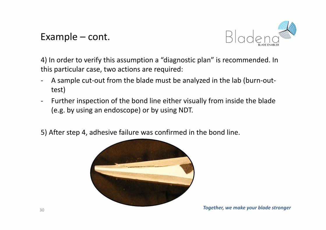
4) In order to verify this assumption a “diagnostic plan” is recommended. In
this particular case, two actions are required:
- A sample cut-out from the blade must be analyzed in the lab (burn-out-
test)
- Further inspection of the bond line either visually from inside the blade
(e.g. by using an endoscope) or by using NDT.
5) After step 4, adhesive failure was confirmed in the bond line.
30
Example – cont.
Together, we make your blade stronger
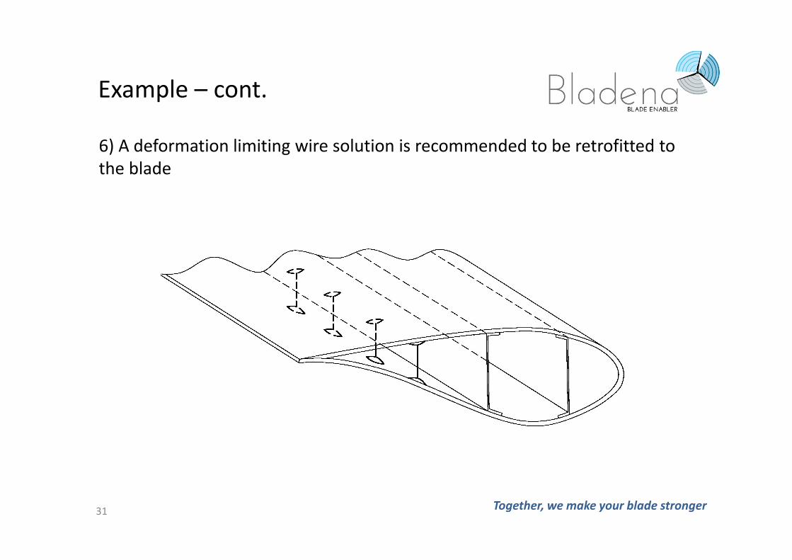
6) A deformation limiting wire solution is recommended to be retrofitted to
the blade
31
Example – cont.
Together, we make your blade stronger
The growing size of the blades have resulted in a change in which type of
loading which is critical and especially the edgewise gravity induced fatigue
loads are more dominant.
Also transverse shear distortion and tension failure in the UD-laminates
become more important.
The increased size of wind turbine blades demanding a better
understanding of their structural behaviour e.g. more complex test loads
and non-linear FEA.
New design and testing procedures must be implemented if the full
potential of the material should be used.
32
Summary
Thank you for your attention
Any Questions?
Any questions please contact:
Find Mølholt Jensen – [email protected]
+45 53700276
www.Bladena.com
Together, we make your blade stronger33