Embed Size (px)
Citation preview
39465 Paseo Padre Parkway. Suite 3700. Fremont, CA 94538 – Tel 510 252 1136 www.beecube.com
© BEEcube Inc. 2014
Challenges and Solutions in Prototyping 5G Radio Access Network
Abstract Breakthroughs in wireless networks will drive commerce and enhance society in entirely new and unexpected ways. A key component of the wireless future will be the widespread deployment of 5G wireless networks. The primary goals of 5G are to support a 1,000-‐fold gain in capacity, connections for at least 100 billion devices, and 10 Gb/s delivered to individual users. Additionally, these new networks will be capable of providing mass low-‐latency connectivity between people, machines, and devices. Deployment of 5G networks is expected to commence in 2020. 5G radio access will be built using evolved existing wireless radio access technologies (RAT) such as LTE and WiFi combined with entirely new technologies.
The detailed technical approaches for 5G are still uncertain, however, several things are clear. Future wireless systems will use existing bandwidth more efficiently by exploiting spatial diversity through massive MIMO, beam forming and related techniques. New allocations of spectrum will be dedicated to cellular, adding to the overall channel capacity. Higher user throughput will be achieved, mainly through carrier aggregation and the use of new frequency bands. Density of urban cell sites will be increased, simultaneously reducing power requirements and allowing much higher spectral re-‐use within a given area. The core network will make increased use of the cloud for both data and control purposes.
5G standards have not yet been set and those companies who can demonstrate working “over-‐the-‐air” systems will have an advantage in getting their ideas/specifications adopted by the international standards bodies.
FPGA based platforms with massive IO and computational capabilities will be the platforms of choice for those companies wishing to influence the 5G standards. These platforms enable rapid prototyping, making it easy to test out algorithms with real data in the field with run times of days or weeks. This White Paper develops a list of criteria that will aid reserchers when selecting such a prototyping platform.
5G Whitepaper
© BEEcube Inc. 2014 2
The 5G Vision: 5G technologies promise to usher in the next wave of a globally connected digital networks by fully realizing the convergence of the communications and IT network infrastructures. Eventually, any mobile application and mobile service will have the potential to connect in reliable and secure ways to anything at anytime – from people to physical things, processes, and content. This connectivity will enable the era of the Internet of things (IoT).
5G will also drive the evolution of the structure of the Internet. Because of convenience and cost benefits, progressively more of the Internet will become wireless. 5G will provide the communications infrastructure for building smart cities. Wireless mobile networks will be called on to reliably deliver services at ever increasing speeds and traffic levels from an expanding set of ubiquitous cloud and fog architectures to a widening set of mobile users, applications, and to the IoT.
To fulfill this vision, future development needs to address the infrastructure limitations to massive capacity and connectivity that currently exist.
Key Technology Challenges of 5G: The fundamental requirements for building 5G wireless networks will be providing capabilities for supporting massive capacity and connectivity, while supporting an increasingly diverse set of services, applications and users – all with extremely different needs.
Mobile wireless networks will become the primary means of network access for person-‐to-‐person, person-‐to-‐machine, and machine-‐to-‐machine connectivity. High definition video and other immersive multimedia interactions will require 10Gb/s data-‐rates and sub-‐millisecond person-‐to-‐person and person-‐to-‐machine latencies. Low latency and extreme reliability will also be essential for mobile industrial automation, vehicular connectivity, and other smart city applications. To meet these requirements, these new networks will need to match wired networks with respect to delivered data-‐rates, quality of service, reliability and security.
5G networks must be built to meet a number of individual end-‐user and enterprise needs:
• 1 to 10 Gb/s data rates to support ultra-‐high definition video and virtualreality applications
• Less than one millisecond latency to support real time mobile control andvehicle-‐to-‐vehicle applications and communications
• Rapid switching time between different radio access technologies to ensure aconsistently seamless delivery of services
5G Whitepaper
© BEEcube Inc. 2014 3
• Mobile network systems will need to expand to support tens of millions of applications and hundreds of billions of machines
• Increased battery life of terminal devices (handsets) • Increased capacity in dense urban environments • Coverage in airplanes and remote areas
To support the required thousand-‐fold capacity increase, it will be necessary to simultaneously make efficient use of all available continuous and non-‐continuous spectrum. Furthermore, freeing up additional spectrum will be required. How all-‐available and new spectrum will be used to achieve 10 Gb/s for end users is a major challenge for designing future 5G systems.
Key Innovations Needed For 5G: To support the 5G vision, technologies will need to evolve in the following ways:
• Utilization of any available spectrum and any access technology for the best delivery of services
• The air-‐interfaces and RAN approaches need to evolve to accommodate massive capacity, a huge number of connections, and ultra-‐fast network speeds
• 5G will need to support new kinds of network deployments, including ultra-‐dense radio networking with self-‐backhauling, direct device-‐to-‐device communications, dynamic spectrum reallocation and radio access infrastructure sharing
• New techniques in advanced waveform modulation, coding, multiple access, and full-‐duplex radios, along with algorithms for efficient and flexible spectrum use are all needed to improve spectrum efficiency and decrease energy per bit
• Key innovations are needed in energy efficient radios for mobile devices and sensors including the use of mmWave frequencies and physically small arrays of antennas for enabling Gb/s speeds with low power consumption
• Integrated designs that implement massive MIMO by combining a large number of radio and antenna elements into a single unit. These designs require more computationally efficient baseband algorithms
• Software-‐defined radio technologies will be integrated into 5G wireless access network architectures to allow flexible use of spectrum and access technology, and allow easy adoption of innovations as they appear
• Cloud-‐based radio access network (C-‐RAN) infrastructures to provide shared on-‐demand computation, storage and network capacity wherever needed
• Very dense and ad hoc deployments of access nodes and backhaul will require systems that self-‐organize their topology, adapt around available spectrum, and allow direct device-‐to-‐device communication
5G Whitepaper
© BEEcube Inc. 2014 4
• Core networks will be based around cloud computing to enable moreflexibility in the creation of new services while supporting integration oflegacy core networks
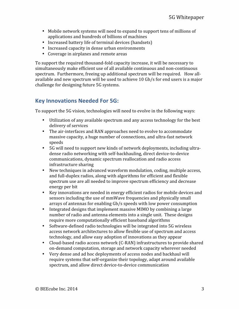
New radio backhaul and new fiber access for the fixed network will be an integral part of next generation commercial network solutions. The following figure gives a basic overview of such a 5G-‐radio access architecture.
Fig. 1 5G: A Technology Vision (Source: Huawei) example of a 5G-radio access architecture
Areas of Active 5G Development There are several communication areas which are being pushed forward rapidly from a development standpoint. These different areas utilize many of the technical innovations described earlier. RF Sampling, Carrier Aggregation, Massive MIMO, E-‐Band Backhaul, and C-‐RAN will be described in more detail below:
Direct RF Sampling of Cellular
With direct RF sampling, signals are immediately moved into the digital domain without the usual intermediate step of frequency down conversion. Similarly on the transmitter side, RF signals are digitally generated and sent directly to DACs for transmission without up-‐conversion. Direct sampling and synthesis of RF signals is a type of software defined radio (SDR), offering many advantages over traditional radio implementation: lower overall system complexity and cost, complete
5G Whitepaper
© BEEcube Inc. 2014 5
flexibility in modulation schemes and bands, simplification of the challenges associated with carrier aggregation, etc.
The SDR concept also allows for the radio to be re-‐configured as upgrades to standards arrive, or if the scope of its operation is changed in the field. A SDR provides flexibility in various dimensions, such as radio access technology (e.g., Wi-‐Fi, LTE, Bluetooth), frequency, and output power.
The software radio concept provides huge advantages for telecommunications applications. In deployments, such as in cellular base-‐stations, standards upgrades frequently occur. A generic hardware platform allows for upgrades of standards to be easily incorporated. Migrations, for example from LTE to newer standards, can simply be accommodated by uploading new software and reconfiguring the radios without any hardware changes, despite the different modulation schemes and frequencies that may be used.
Furthermore, the effectiveness of proposed baseband and air-‐interface techniques is uncertain, and radio developers need to be able to rapidly explore design alternations, and to do it in the context of real-‐time real world signals. A hardware platform capable of SDR, is an ideal vehicle for R&D where exploring a huge design space is needed.
While direct RF sampling and synthesis has long been desired, only recently has Digital-‐to-‐Analog Converters (DACs) and Analog-‐to-‐Digital Converters (DACs) technology progressed to the point that 5GHz direct RF sampling is possible and up to 10GHz will be possible by 2020.
Carrier Aggregation
Carrier aggregation is a class of techniques that will be key to satisfying the basic requirement of 5G deployments to make effective use of all available spectrum. Carrier aggregation allows a wireless provider to combine and operate separate, and often non-‐contiguous, blocks of spectrum as one. This will allow operators to take advantage of all presently available spectrum and allow newly available spectrum to be integrated. It will increase the network’s ability to provide consistent performance along with increased capacity.
Carrier Aggregation is an important feature of LTE Advanced, because a key to achieving higher data rates with LTE is to enable network operators to effectively employ bandwidths wider than the 20MHz currently specified in LTE today. A complicating factor is that the nature of spectrum allocation over the years is such that most operators have a mix and match of spectrum within and between frequency bands. This trend is expected to continue as we move towards 5G and as new spectrum becomes available.
In the simplest form of carrier aggregation, carriers are contiguous and lie within the same frequency band. In this case, it is feasible for a mobile device to handle the signals using a single transceiver, providing it is able to operate efficiently over the
5G Whitepaper
© BEEcube Inc. 2014 6
aggregate bandwidth. With intra-‐band non-‐contiguous carrier aggregation, the carriers lie within the same frequency band, but they are not adjacent. In this case it might be necessary for the mobile device to use a separate transceiver for each carrier. The most advanced form of carrier aggregation is based on inter-‐band non-‐contiguous carriers. In this case, the carriers fall in different parts of the radio spectrum. While challenging, particularly for mobile devices, the ability to combine such carriers is particularly useful for network operators with fragmented spectrum allocations. This form of carrier aggregation is the most promising form for satisfying the needs of 5G networks. Carriers from differing bands, possibly including ISM Wi-‐Fi bands along with traditional and new regulated bands, would be combined to greatly increase link data rates. In this advanced form it is necessary to include a transceiver for each carrier, creating the challenge of ensuring that the device can operate in multiple bands simultaneously. This requirement could significantly raise system design complexity, cost, and power consumption.
Recent advances in wide-‐band DAC and ADC technologies permit direct IF-‐ and RF-‐waveform sampling and synthesis. This capability provides an attractive alternative to the implementation of separate analog transceivers paths for separate carriers. Here a large block of spectrum is directly sampled/synthesized from/to the digital domain. Digital processing is used to effectively implement a transceiver path for each carrier and eliminates the challenges of the coordination of separate analog front-‐ends.
Next-‐Generation E-‐Band for 5G backhaul
The traditional microwave frequency bands (6 to 42GHz) are almost depleted in the face of fast-‐growing mobile broadband demand, making microwave expansion to the higher bands inevitable. E-‐Band (71-‐86GHz) is abundant and adaptable for dense deployment, making it a key trend in carrier-‐class wireless transmission. E-‐Band microwave can deliver ultra-‐broadband networking with enhanced reliability.
E-‐Band offers a number of benefits including pencil-‐beaming that enhance frequency reuse and interference protection, making it ideal for dense 5G site backhaul. When allocating microwave spectrum, operators can flexibly use one channel or combine multiple channels. Spectrum can be flexibly allocated in dense urban areas for backhaul purposes, and multiple operators can deploy E-‐Band microwave networks in the same area without interference.
As of the end of 2012, over 40 markets globally opened their E-‐Band frequency resources. To encourage more applications, most markets offer free or modestly charged E-‐Band frequency bands, easing the microwave spectrum shortage and reducing operator investment.
Existing E-‐Band microwave equipment has evolved from enterprise applications, and has limitations in transport capacity, spectrum efficiency, and network management due to the use of low order modulation schemes with low spectral efficiency and limited support for clock synchronization. Growing mobile
5G Whitepaper
© BEEcube Inc. 2014 7
broadband and 5G services will push the transmission capacity of a single base station to the 100’s of Gbps range, and 5G networks will also require greater synchronization and network management.
To meet the needs of 5G networks, next-‐generation E-‐Band will need to support aggressive adaptive modulation, coding, compression, and even MIMO schemes to enhance the capacity and reliability of microwave links, while minimizing the impact of bad weather and environmental changes. Advanced radio access technologies will demand tighter requirements on clock synchronization in backhaul networks. Current generation systems support Synchronous Ethernet and IEEE 1588v2 precision time protocol (PTP), but future systems will need to go beyond these standards.
C-‐RAN
The radio equipment within cellular base-‐stations is conventionally divided into two distinct units, the remote radio-‐unit (RRU), or remote radio-‐head (RRH), and the base-‐band processing unit (BBU). The RRU provides the physical interface to the air and the BBU handles the processing associated with data modulation and coding, along with controlling the interaction between the cell tower and the mobile units. Traditionally, both these units have been located at the cell tower.
Centralized Radio Access Network, also referred to as Cloud-‐RAN or C-‐RAN, is a new cellular network architecture important for future mobile networks. In this architecture, the BBUs are geographically separated from the RRUs. Hundreds to thousands of distributed RRUs are connected to a centralized pool of base-‐band processing units (BBUs). C-‐RAN uses virtualization technology from cloud computing to achieve dynamic shared resource allocation. A key characteristic of C-‐RAN is its ability to implement new cellular networks features such as Coordinated MultiPoint (CoMP) with very low latency between multiple radio heads.
C-‐RAN’s centralized base-‐band processing offers many advantages over traditional cellular base-‐station architectures. Consolidation, pooling, and virtualization of base-‐band processing resources leads to lower costs of deployment, as redundant capabilities and over-‐commissioning are avoided, saving on equipment costs and power consumption. Furthermore, a centralized localization of base-‐band processing results in lower routine maintenance costs. Therefore, overall Cloud-‐RAN will lead to lower total cost of ownership.
Another important advantage to C-‐RAN is that it permits a level of coordination among cellular base-‐stations that is impractical in a traditional distributed architecture. Cells overlap and therefore, mobile devices, or UEs, often are within range of more than one cell tower. Overlapping will be more pronounced as deployments move to smaller cells and higher access point densities. With consolidated base-‐band processing, any BBU can talk with high bandwidth and low latency with any other BBU within the pool, hand-‐off between cells is eased and a new range of improved coordination and control algorithms are enabled. Furthermore, with aggregation and synchronization of data-‐streams to/from
5G Whitepaper
© BEEcube Inc. 2014 8
multiple base stations, advanced signal processing techniques such as cooperative-‐MIMO can be used to improve signal reliability and data-‐rates. This level of cooperation is only practical with tightly coupled low-‐latency connections among signal paths of the access points.
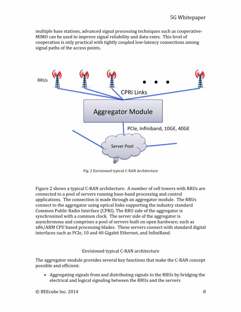
Fig. 2 Envisioned typical C-‐RAN Architecture
Figure 2 shows a typical C-‐RAN architecture. A number of cell towers with RRUs are connected to a pool of servers running base-‐band processing and control applications. The connection is made through an aggregator module. The RRUs connect to the aggregator using optical links supporting the industry standard Common Public Radio Interface (CPRI). The RRU side of the aggregator is synchronized with a common clock. The server side of the aggregator is asynchronous and comprises a pool of servers built on open hardware; such as x86/ARM CPU based processing blades. These servers connect with standard digital interfaces such as PCIe, 10 and 40 Gigabit Ethernet, and InfiniBand.
Envisioned typical C-‐RAN architecture
The aggregator module provides several key functions that make the C-‐RAN concept possible and efficient:
• Aggregating signals from and distributing signals to the RRUs by bridging the electrical and logical signaling between the RRUs and the servers
. . ."Aggregator(Module(
Server(Pool(
CPRI(Links(
PCIe,(Infiniband,(10GE,(40GE(
RRUs(
5G Whitepaper
© BEEcube Inc. 2014 9
• Recovering and synchronizing the clocks among the RRUs
• Functioning as a “smart-‐router” that distributes and load-‐balances tasks among the servers
• Off-‐loading time-‐critical control functions from the servers (i.e., reducing system latency)
• Signal processing for combining signals from multiple RRUs
• Time stamping the data passed to the server pool
The Path To A New Standard Creating a new standard is a complicated process with various manufacturers, carriers, government agencies and academics collectively formulating the new standard. Their work must be documented in excruciating detail, so carriers can use infrastructure from different manufacturers with the ability to seamlessly talk to handsets from other companies.
5G poses many, little understood or uncovered, engineering challenges. Developers need a very flexible yet high-‐performance platform for rapidly investigating a range of technical approaches and design points. The design space exploration process needs to take place in the context of real world situations with real-‐time streaming data. Researchers utilizing flexible platforms can better adapt their solutions as the standards solidify.
Traditionally, design space exploration has been a costly and laborious enterprise involving long development cycles and many compromises. Often only a small number of ideas can be tried out because designers are given a limited amount of time. Another major challenge relates to the quality of results of experimentation and analysis. Conventional development techniques such as simulation use limited data sets and often non-‐real-‐time data. Therefore it is difficult to have full confidence in the simulated results. In-‐field testing with real data is the most effective and expeditious way to verify new techniques.
An alternative to simulation is development of project specific custom hardware prototyping platforms. These systems are costly and difficult to develop and program because they require the use of state-‐of-‐the-‐art data converters and high-‐end FPGAs. While most development engineers have a good handle on the details of implementation of a particular set of algorithms, the details of system-‐level programming for integrating high-‐speed interfaces, with clock generators and synchronizers, and external memory controllers, along with custom computing cores is more elusive and results in a cumbersome and error prone process. Vendor supplied tools and cores offer limited help. A mature software development environment with a verified set of firmware blocks is needed to fully address these problems.
5G Whitepaper
© BEEcube Inc. 2014 10
In addition to ease of software/firmware development and deployment, 5G development platforms have very specific technical requirements. The platforms need to be able to simultaneously capture and piece together multiple bands of spectrum across a wide frequency range. This requires wide band digitization across multiple GHz. This is already implemented in the current LTE standards, 44 bands extend from 600MHz to 6 GHz. Teraops processing rates are needed to support the needs of massive antenna arrays and MIMO approaches, along with new modulation and coding schemes. To meet the needs of cloud-‐based and distributed cooperative schemes, development platforms will need to provide exceptional clock generation and recovery resources having tight jitter specifications. For ease of scaling system performance and to provide a flexible range of deployments, development platforms require Terabits per second of I/O throughput and many inter-‐module connectivity options and topologies.
Some of the technical underpinnings of 5G have already been developed: spatial diversity, massive MIMO, carrier aggregation, and C-‐RAN. The current challenge is in expanding these techniques, combining them in new ways, and implementing in new frequency bands. Here the interaction of radio signals with the environment is beyond the scope of modeling and simulation and therefore systems must be built and tested in the real world. For these reasons, measured experimental data from field trials are most compelling arguments during the creation phase of new standards. This leads to a conundrum. How will the necessary data be gathered to drive the standards when the hardware architecture has yet to be finalized?
The Ideal Wireless Infrastructure Prototyping Platform The ideal platform combines many of the following attributes:
• Flexible programming model: The programming model must support the major existing design flows of C, C-‐to-‐Gates, VHDL, Verilog, and MATLAB®/Simulink®.
• Ability to easily migrate designs into production: Any 5G prototype will necessarily be complex. Developing new algorithms in a proprietary language will result in an orphan design that must be re-‐created in order to move to production.
• Real-‐Time operation: Test and measurement hardware possesses many of the technical attributes required of a 5G prototype. However, none of the test equipment currently on the market supports terabits per second of real-‐time data for minutes or hours, let alone the days or weeks needed for true field trials.
• Interface to 10’s of terabits per second: 5G represents a thousand fold increase in data throughput. Any prototype system used must be capable of scaling to interface to hundreds of optical fibers.
• Tera MACs per second: The DSP processing power required to implement high order modulation schemes across many antennas and many sectors, as
5G Whitepaper
© BEEcube Inc. 2014 11
with massive-‐MIMO, is immense. Tens of thousands to hundreds of thousands of Multiply Accumulate (MAC) units will be required, with each running at hundreds of MHz.
• Compliance to legacy standards: Any basestation deployed will likely be required to support the existing standards, including LTE-‐Advanced.
• Modular architecture: Analog and digital sections of the prototype must be tightly coupled, yet distinct, to allow for different frequency bands and different bandwidth solutions to be explored.
• Ability to scale: Exploring ideas usually start on a small system and then gradually increase in scale until multiple full-‐scale macro cells are deployed. Being able to use the same basic hardware across this continuum is a huge advantage.
• Clock jitter <500fs across racks of gear: One of the biggest impediments to prototyping large systems is maintaining clock integrity across racks of gear.
• Efficient connection to the cloud: One of the major areas of architectural innovation is how to distribute as much processing as possible to the cloud, in order to leverage economies of scale and minimize deployment of distributed processing power at cell tower sites that are only used during peak times. Connection to the cloud requires 10GE, 40GE, PCIe or even InfiniBand.
• Very accurate time stamping: Techniques such as CoMP, which effectively use multiple cell sites simultaneously to communicate with an individual terminal, require that data received from individual RRUs be accurately time stamped, so the relative time delays from user to each tower can be accurately calculated. Sub-‐nanosecond accuracies allow Doppler shifts to be exploited.
• Ability to extract an embedded clock from a data stream such as CPRI.
5G Development Using Rapid Prototyping Platforms Traditionally OEMs have built their own hardware platforms for prototyping purposes. In today’s environment, nimble, fast moving companies that concentrate on their core competencies usually become first to market. While a companies core competency may be in design and manufacture of high volume production boards they often will not excel in building a short-‐lived prototype platform that will see internal volumes of < 100 units. OEMs today should only produce their own prototyping platform if a suitable platform cannot be obtained commercially. With commercial platforms available today from various companies the need to allocate resources to designing custom hardware is diminished.
BEEcube is one such company offering advance prototyping platforms specifically designed for 5G development. BEEcube products are carrier grade and appropriate for testing ideas in the field over the entire engineering cycle. BEEcube software
5G Whitepaper
© BEEcube Inc. 2014 12
allows quick changes in the field and immediate deployment. With the ease of software simulation, BEEcube products offer real-‐time testing with real-‐world data. BEEcube platforms are able to support prototyping 5G systems today and address the challenges previously stated.
Digital RF Sampling of Cellular
Direct RF sampling and synthesis up to 6GHz is a goal of Software Defined Radio, but has only recently become practical. High speed Digital-‐to-‐Analog Converters (DACs) and Analog-‐to-‐Digital Converters (DACs) enable direct RF Sampling up to the desired range. BEEcube has developed a modular architecture in its rapid prototyping platforms, whereby high performance analog interfaces are supported via FMC cards connected to the motherboard.
Currently, modules with sample rates up to 5Gsps are available, allowing 2.5GHz of spectrum to be directly synthesized or digitized and passed to/from the FPGA motherboard for modulation/demodulation and any other processing required. The analog FMC cards support the first and higher Nyquist zones, so one can examine the entire spectrum below 2.5GHz or blocks of 2.5GHz spectrum at higher frequencies. Other FMC modules are available that support selection of a narrower bandwidth between 250MHz to 2.5GHz with higher resolution.
High speed DACs and ADCs are notoriously difficult to integrate effectively into real systems. They are interleaved for the highest performance and require extremely stable clocks, with clock jitter requirements below 500fs. The BEEcube BEE7 platform provides a typical clock jitter less than 300fs when measured phase noise offset from 100Hz and 10MHz at 307.2MHz reference clock. These DACs and ADCs also require special training sequences which set the phase of the data strobes to maximize data integrity when pushing data to or pulling data from the high speed devices. BEEcube’s platforms perform all the training sequences when the boards first boot up, hence the developer never need to address these low level details.
Carrier Aggregation
BEEcube products provide a very effective platform for the development of advanced carrier aggregation. BEEcube FMC cards with wideband ADCs and DACs enable direct RF and IF sampling, dramatically simplify the analog signal paths. Furthermore, the substantial raw digital computational capabilities of the BEEcube platforms permit implementation of multiple simultaneous transmitter and receiver paths along with MIMO processing.
BEEcube platforms have been proven effective for the development of advanced carrier aggregation solutions. Utilizing the BEE7 platform and FMC converter cards, a BEEcube customer demonstrated a system operating in the 5 GHz WiFi bands using carrier aggregation along with MIMO techniques to achieve greater than 10 Gbps data-‐rates. In this approach the entire band is down-‐converted to analog IF and then directly sampled. The demonstrated data-‐rate is 100 times higher than that of current state-‐of-‐the-‐art commercially available Wi-‐Fi technology.
5G Whitepaper
© BEEcube Inc. 2014 13
Next-‐Generation E-‐Band for 5G Backhaul
The BEE7 is well suited for E-‐band microwave solutions with computational capabilities in excess of 5 TMACs (1012 multiply/add operations per second), and 64GB of on-‐board DRAM allow demonstration of advanced baseband processing employing aggressive modulation, coding, and compression techniques. The BEE7 has four FMC slots enabling high-‐speed analog interfaces including mmWave. The BEE7’s exceptional clock generation, recovery resources and ultra-‐low jitter specifications, allows development and implementation of advanced clock synchronization schemes. Furthermore, the ATCA blade form-‐factor of the BEE7 eases integration with other telecommunication equipment, such as switches and system controllers, making it a natural choice for field deployment.
The BEE7 blade contains 64GB of 1333MHz DDR3 on-‐board memory enabling a powerful design methodology. Algorithms can be developed in the double precision floating point world of MATLAB and then migrated a piece at a time into fixed point implementations operating in real time. For example, for a channel of 1GHz bandwidth, when using in-‐phase (I) and quadrature (Q) samples, a sample rate of at least 1Gsps is required to create and capture this spectrum. If the modulator requires 16 bits of I and Q data, the aggregate data rate at the two DACs is 4GB/s. A MATLAB simulation can be run producing 16 seconds of real time data, the 64GB of resulting data downloaded into the BEE7 blade and then played over the air and received by another BEE7 blade. Using this technique, algorithms can be tested over the air and when a suitable algorithm has been created, the algorithm can be mapped into fixed-‐point hardware, one piece at a time. By continuing to monitor over the air test results, one can see the effects of quantization and other hardware limitations, making design adjustments as necessary.
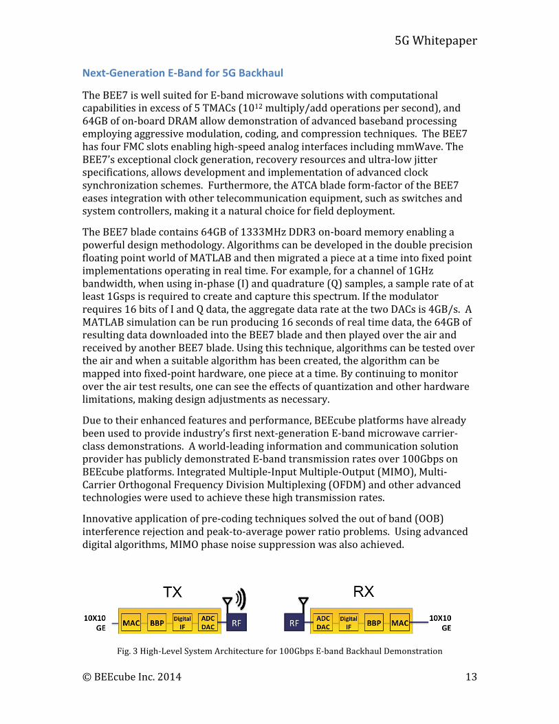
Due to their enhanced features and performance, BEEcube platforms have already been used to provide industry’s first next-‐generation E-‐band microwave carrier-‐class demonstrations. A world-‐leading information and communication solution provider has publicly demonstrated E-‐band transmission rates over 100Gbps on BEEcube platforms. Integrated Multiple-‐Input Multiple-‐Output (MIMO), Multi-‐Carrier Orthogonal Frequency Division Multiplexing (OFDM) and other advanced technologies were used to achieve these high transmission rates.
Innovative application of pre-‐coding techniques solved the out of band (OOB) interference rejection and peak-‐to-‐average power ratio problems. Using advanced digital algorithms, MIMO phase noise suppression was also achieved.
Fig. 3 High-‐Level System Architecture for 100Gbps E-‐band Backhaul Demonstration
5G Whitepaper
© BEEcube Inc. 2014 14
C-‐RAN
The BEEcube BEE7 is an ideal platform for implementation of the CPRI aggregator function in C-‐RAN. It includes a set of specialized circuits, such as PPLs and jitter cleaners that enable clock recovery and high-‐precision clock synchronization among the RRUs. At the hardware level and with specialized cores, the BEE7 supports all the necessary data interfaces of C-‐RAN, including optical CPRI, 10/40 Gigabit Ethernet, and PCIe. With 5 TMACs the BEE7 platform provides the computational needs of C-‐RAN advanced signal processing and control algorithms. Furthermore, the ATCA form-‐factor of the BEE7 makes it appropriate for field deployment, allows multiple BEE7 blades to operate in concert and allows efficient integration with other telecommunication equipment.
The other critical requirement is optical interconnect bandwidth. One BEE7 blade can support a total of 144 full duplex 10Gbps optical pipes. The protocols currently supported include CPRI (up to 9.83Gb/s), 10GE, 40GE and PCIe gen 3. A single BEE7 blade can easily support 100 CPRI lines from RRHs, and interface to servers using the remaining 44 optical interconnect lines. Using the advanced synchronization and clocking of the BEE7, a single ATCA 14-‐slot chassis filled with BEE7 blades can interface 1,000 CPRI lines to the cloud and operate indefinitely at line speed.
Massive MIMO
Another approach to increase link data throughput and link quality is to increase the number of physical antennas. When physically installed at the same central location, a large number of antennas can beam form to multiple users to improve link quality. Innovative spatial coding techniques can provide increased multi-‐user capacity versus existing OFDM based solutions, at the expense of much stricter phase alignment requirements for massive MIMO RF subsystems.
One of the key physical layer implementation challenges is how to keep all the antenna local oscillator (LO) clocks in synch with ultra-‐low phase noise and phase drift. An example is a distributed massive MIMO solution, where groups of antennas and RF subsystems may be physically separated by as much as 2 kilometers, while still connected to the same base band processor in a coordinated approach. The traditional LO clock distribution method of a centralized clock generator using length matched SMA cables to each antenna is not only expensive, but also impossible for distributed massive MIMO installations. Therefore the combination of CPRI style embedded clock distribution with IEEE-‐1588 synchronization is crucial for the success of any massive MIMO solution.
Looking first at the narrow band MIMO, BEEcube’s nanoBEE and MegaBEE platforms both contain a SDR with 56MHz bandwidth tunable between 70MHz and 6GHz in most wideband LTE frequency bands. FDD and TDD modes are both supported. nanoBEE supports 2x2 or 4x4 MIMO. The MegaBEE supports 8x8 MIMO in a 1U enclosure. Multiple MegaBEEs can be aggregated together in a 19” rack for easy expansion from 16x16 up to 256x256 narrow band MIMO. nanoBEE and
5G Whitepaper
© BEEcube Inc. 2014 15
megaBEE are both fully 3GPP compatible, meeting the +23dBm output power and -‐94dBm input sensitivity specifications. With the same ultra-‐low jitter CPRI clock recovery as proven on the BEE7 system, megaBEE systems can achieve the LO clock requirements of both centralized and distributed massive MIMO solutions.
For wideband MIMO greater than 500MHz bandwidth, BEE7 is the preferred solution. At 1GHZ RF bandwidth, each channel requires up to 32Gbps full duplex digital I/O throughput, therefore a full crossbar connection among 32 channels requires over 1Tbps bisection I/O bandwidth for the processing system. With over 1.4Tbps total optical I/O bandwidth per BEE7 blade, a single 14 slot ATCA chassis hosting 8 BEE7 blades can provide 32 streams of 1GHz RF channels with real-‐time full data interconnect. In this instance, 4 FMC slots per blade and 2 channels of ADC or DAC per FMC site drive the number of BEE7 blades.
When used in a millimeter wave massive MIMO system, each RF stream typically drives a small antenna array consisting of 4 to 16 elements. In the above example having 32 RF streams, 128 to 512 physical antennas would be used in a 1GHz mmWave MIMO solution.
Summary Companies that can demonstrate their objectives working at line speed are more likely to have their ideas incorporated into the next generation of wireless standards. Companies that can leverage existing commercial platforms during the algorithm exploration phase can save the 12 months it realistically takes to build their own platform.
BEEcube offers platforms today that possess the scalability, clocking characteristics and computational bandwidth necessary to prototype the most demanding 5G demonstrations. This capability is provided with an open programming model that allows users to import their legacy IP while also allowing them to export their designs to the manufacturing and implementation teams when the designs have been refined sufficiently for production.
BEEcube Inc. 39465 Paseo Padre Parkway Suite 3700 Fremont, CA 94538 Tel 510 252 1136 www.beecube.com [email protected]