Embed Size (px)
Citation preview
Challenges with Power Aware
Simulation and Verification Methodologies
Divyeshkumar Vora
Staff Design Engineer
© Accellera Systems Initiative 1
Agenda
• Introduction
• Power-aware (PA) simulation overview
• Integrated PA Verilog model
• Liberty based assertions
• UPF Macro models using successive refinement
• Library validation flow
• Summary
© Accellera Systems Initiative 2
Introduction
• Constant push to make electronic products both energy and power efficient resulted in increased design implementation complexity
• It is of utmost importance to catch any issue early in the implementation cycle
• IEEE-1801 (a.k.a. Unified Power Format - UPF), allows users to define the design power intent which can be used during the entire implementation flow
• UPF enables user to perform power intent verification from the RTL stage and Power Aware (PA) simulation is one such verification
© Accellera Systems Initiative 3
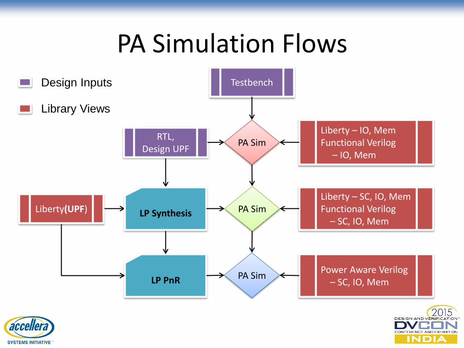
PA Simulation Flows
PA Sim
LP PnR
PA Sim
PA Sim
LP Synthesis Liberty(UPF)
RTL, Design UPF
Liberty – IO, Mem Functional Verilog – IO, Mem
Liberty – SC, IO, Mem Functional Verilog – SC, IO, Mem
Power Aware Verilog – SC, IO, Mem
Testbench
Library Views
Design Inputs
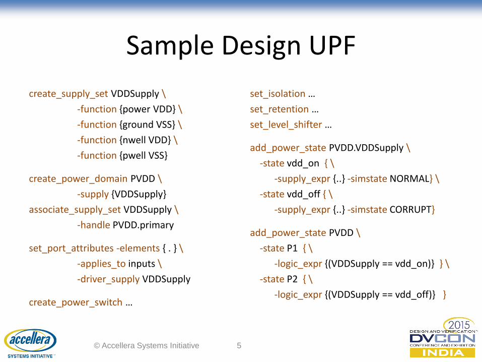
Sample Design UPF
create_supply_set VDDSupply \
-function {power VDD} \
-function {ground VSS} \
-function {nwell VDD} \
-function {pwell VSS}
create_power_domain PVDD \
-supply {VDDSupply}
associate_supply_set VDDSupply \
-handle PVDD.primary
set_port_attributes -elements { . } \
-applies_to inputs \
-driver_supply VDDSupply
create_power_switch …
set_isolation …
set_retention …
set_level_shifter …
add_power_state PVDD.VDDSupply \
-state vdd_on { \
-supply_expr {..} -simstate NORMAL} \
-state vdd_off { \
-supply_expr {..} -simstate CORRUPT}
add_power_state PVDD \
-state P1 { \
-logic_expr {(VDDSupply == vdd_on)} } \
-state P2 { \
-logic_expr {(VDDSupply == vdd_off)} }
© Accellera Systems Initiative 5
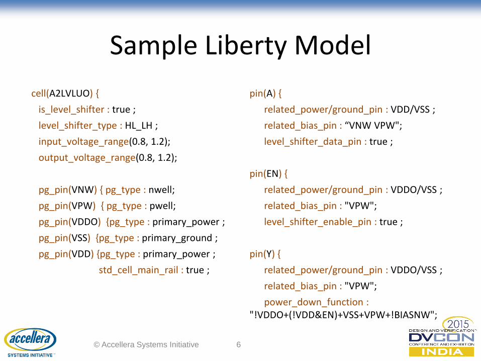
Sample Liberty Model
cell(A2LVLUO) {
is_level_shifter : true ;
level_shifter_type : HL_LH ;
input_voltage_range(0.8, 1.2);
output_voltage_range(0.8, 1.2);
pg_pin(VNW) { pg_type : nwell;
pg_pin(VPW) { pg_type : pwell;
pg_pin(VDDO) {pg_type : primary_power ;
pg_pin(VSS) {pg_type : primary_ground ;
pg_pin(VDD) {pg_type : primary_power ;
std_cell_main_rail : true ;
pin(A) {
related_power/ground_pin : VDD/VSS ;
related_bias_pin : “VNW VPW";
level_shifter_data_pin : true ;
pin(EN) {
related_power/ground_pin : VDDO/VSS ;
related_bias_pin : "VPW";
level_shifter_enable_pin : true ;
pin(Y) {
related_power/ground_pin : VDDO/VSS ;
related_bias_pin : "VPW";
power_down_function : "!VDDO+(!VDD&EN)+VSS+VPW+!BIASNW";
© Accellera Systems Initiative 6
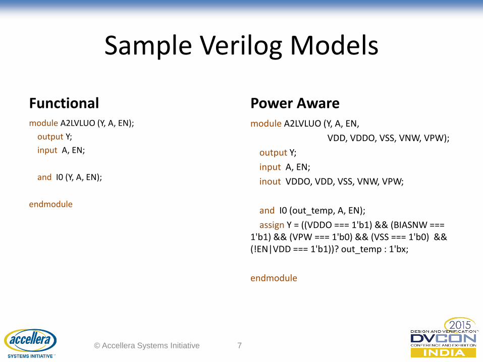
Sample Verilog Models
Functional module A2LVLUO (Y, A, EN);
output Y;
input A, EN;
and I0 (Y, A, EN);
endmodule
Power Aware module A2LVLUO (Y, A, EN,
VDD, VDDO, VSS, VNW, VPW);
output Y;
input A, EN;
inout VDDO, VDD, VSS, VNW, VPW;
and I0 (out_temp, A, EN);
assign Y = ((VDDO === 1'b1) && (BIASNW === 1'b1) && (VPW === 1'b0) && (VSS === 1'b0) && (!EN|VDD === 1'b1))? out_temp : 1'bx;
endmodule
© Accellera Systems Initiative 7

INTEGRATED VERILOG MODEL
Problem Statement
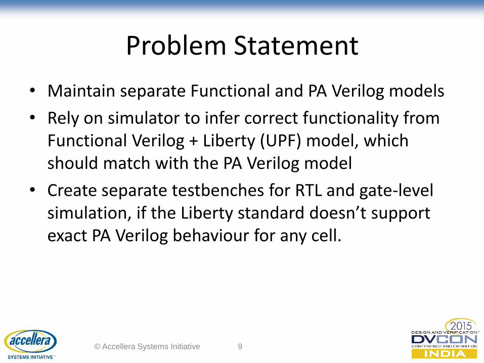
• Maintain separate Functional and PA Verilog models
• Rely on simulator to infer correct functionality from Functional Verilog + Liberty (UPF) model, which should match with the PA Verilog model
• Create separate testbenches for RTL and gate-level simulation, if the Liberty standard doesn’t support exact PA Verilog behaviour for any cell.
© Accellera Systems Initiative 9
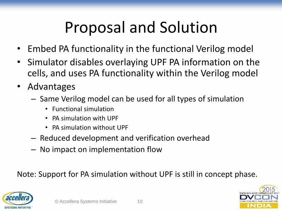
Proposal and Solution • Embed PA functionality in the functional Verilog model
• Simulator disables overlaying UPF PA information on the cells, and uses PA functionality within the Verilog model
• Advantages – Same Verilog model can be used for all types of simulation
• Functional simulation
• PA simulation with UPF
• PA simulation without UPF
– Reduced development and verification overhead
– No impact on implementation flow
Note: Support for PA simulation without UPF is still in concept phase.
© Accellera Systems Initiative 10
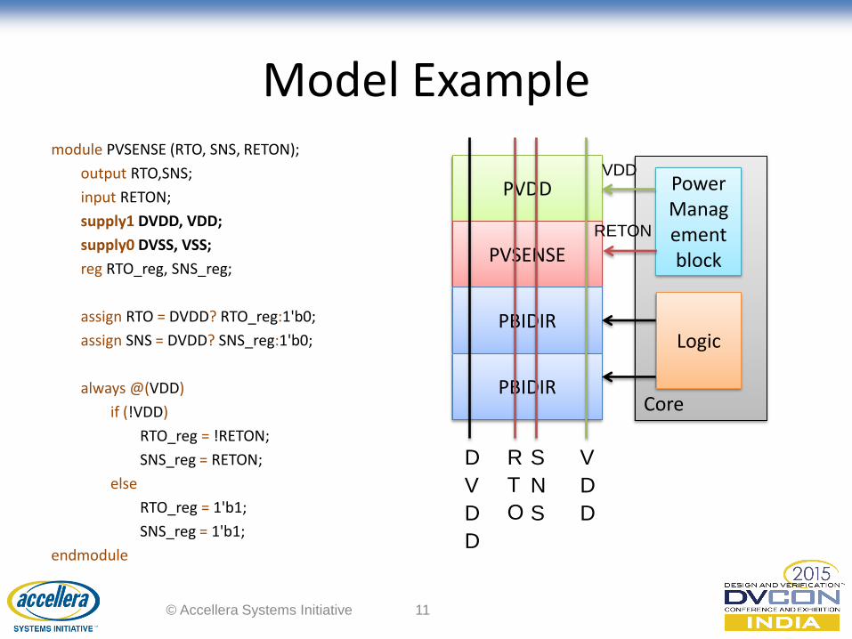
Model Example module PVSENSE (RTO, SNS, RETON);
output RTO,SNS;
input RETON;
supply1 DVDD, VDD;
supply0 DVSS, VSS;
reg RTO_reg, SNS_reg;
assign RTO = DVDD? RTO_reg:1'b0;
assign SNS = DVDD? SNS_reg:1'b0;
always @(VDD)
if (!VDD)
RTO_reg = !RETON;
SNS_reg = RETON;
else
RTO_reg = 1'b1;
SNS_reg = 1'b1;
endmodule
© Accellera Systems Initiative 11
PVDD
PVSENSE
PBIDIR
PBIDIR
D
V
D
D
R
T
O
S
N
S
V
D
D
Core
Power Management block
Logic
VDD
RETON
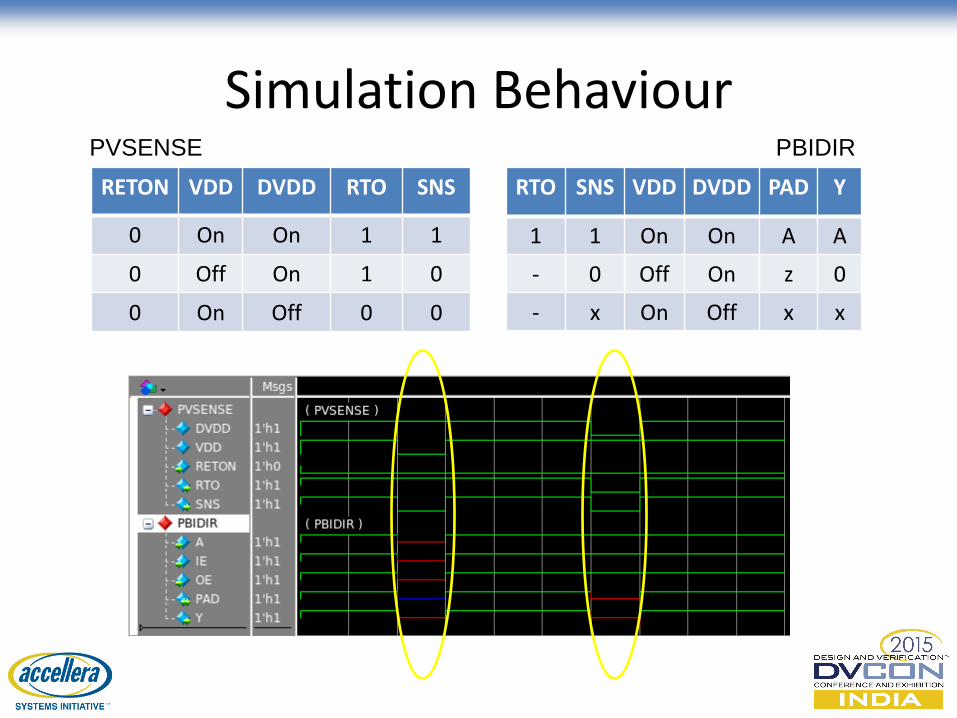
Simulation Behaviour
RTO SNS VDD DVDD PAD Y
1 1 On On A A
- 0 Off On z 0
- x On Off x x
RETON VDD DVDD RTO SNS
0 On On 1 1
0 Off On 1 0
0 On Off 0 0
PVSENSE PBIDIR

LIBERTY BASED ASSERTIONS
Problem Statement
• Today’s designs exhibit complex retention capabilities
– Even basic save and restore operation could depend on complex sequences of various control signals
– Any incorrect state of the register controls like clock, set, reset or violation of power control sequence could cause incorrect retention values
• Synthesis tools pick retention cells only based on the cell classification and functionality
– Cell-level protocol requirements are not enforced
– If escapes happen, it can lead to silicon failures
© Accellera Systems Initiative 14
Proposal and Solution
• Use low power attributes defined in Liberty to infer assertion proofs and firings
– Instrument an SV based assertion within the tool to check the protocol behaviour
– Validate assertion against applied vectors during dynamic simulation, and obtain the time when the assertion fails to ease the debugging
© Accellera Systems Initiative 15
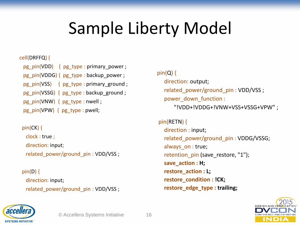
Sample Liberty Model
cell(DRFFQ) {
pg_pin(VDD) { pg_type : primary_power ;
pg_pin(VDDG) { pg_type : backup_power ;
pg_pin(VSS) { pg_type : primary_ground ;
pg_pin(VSSG) { pg_type : backup_ground ;
pg_pin(VNW) { pg_type : nwell ;
pg_pin(VPW) { pg_type : pwell;
pin(CK) {
clock : true ;
direction: input;
related_power/ground_pin : VDD/VSS ;
pin(D) {
direction: input;
related_power/ground_pin : VDD/VSS ;
pin(Q) {
direction: output;
related_power/ground_pin : VDD/VSS ;
power_down_function :
"!VDD+!VDDG+!VNW+VSS+VSSG+VPW" ;
pin(RETN) {
direction : input;
related_power/ground_pin : VDDG/VSSG;
always_on : true;
retention_pin (save_restore, "1");
save_action : H;
restore_action : L;
restore_condition : !CK;
restore_edge_type : trailing;
© Accellera Systems Initiative 16
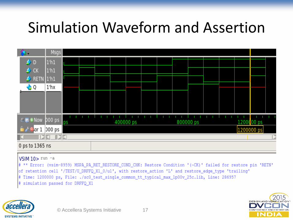
Simulation Waveform and Assertion
© Accellera Systems Initiative 17
UPF MACRO MODELS USING SUCCESSIVE REFINEMENT
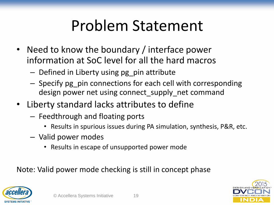
Problem Statement
• Need to know the boundary / interface power information at SoC level for all the hard macros – Defined in Liberty using pg_pin attribute
– Specify pg_pin connections for each cell with corresponding design power net using connect_supply_net command
• Liberty standard lacks attributes to define – Feedthrough and floating ports
• Results in spurious issues during PA simulation, synthesis, P&R, etc.
– Valid power modes • Results in escape of unsupported power mode
Note: Valid power mode checking is still in concept phase
© Accellera Systems Initiative 19
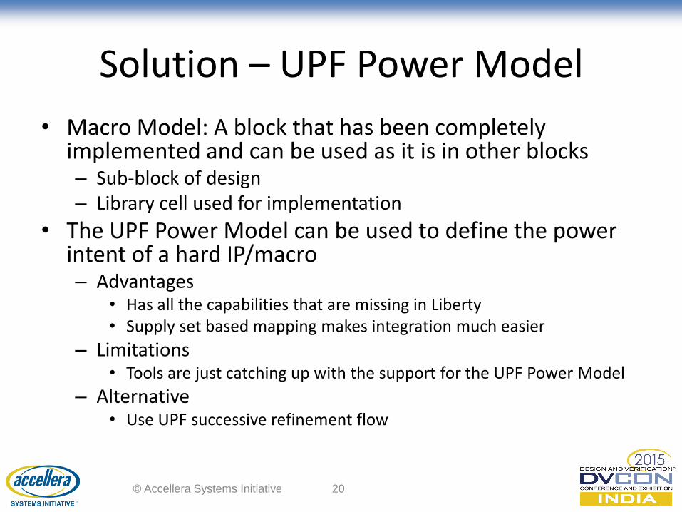
Solution – UPF Power Model
• Macro Model: A block that has been completely implemented and can be used as it is in other blocks – Sub-block of design – Library cell used for implementation
• The UPF Power Model can be used to define the power intent of a hard IP/macro – Advantages
• Has all the capabilities that are missing in Liberty • Supply set based mapping makes integration much easier
– Limitations • Tools are just catching up with the support for the UPF Power Model
– Alternative • Use UPF successive refinement flow
© Accellera Systems Initiative 20
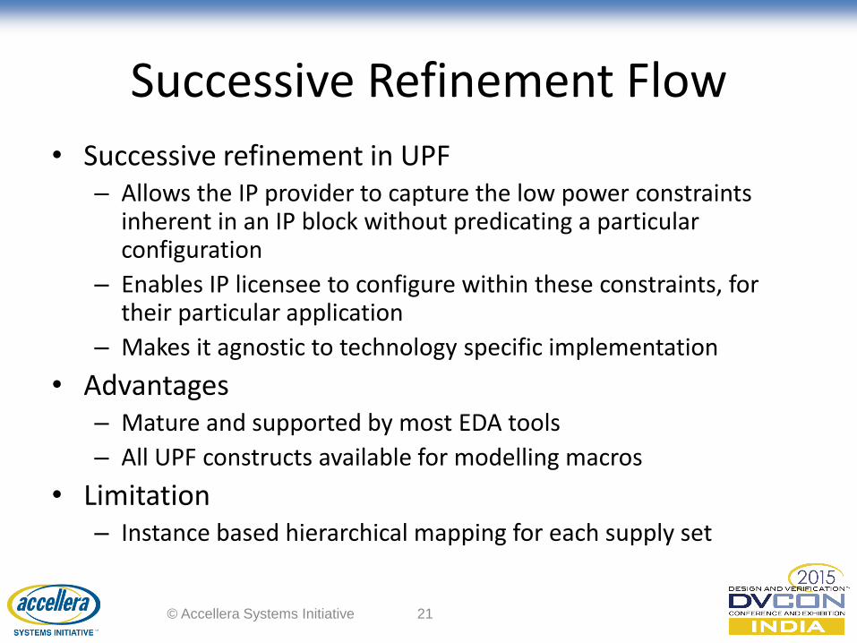
Successive Refinement Flow
• Successive refinement in UPF – Allows the IP provider to capture the low power constraints
inherent in an IP block without predicating a particular configuration
– Enables IP licensee to configure within these constraints, for their particular application
– Makes it agnostic to technology specific implementation
• Advantages – Mature and supported by most EDA tools
– All UPF constructs available for modelling macros
• Limitation – Instance based hierarchical mapping for each supply set
© Accellera Systems Initiative 21
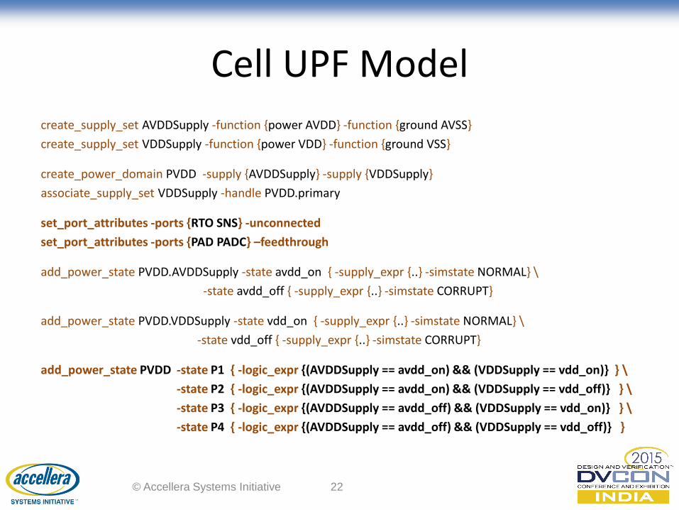
Cell UPF Model
create_supply_set AVDDSupply -function {power AVDD} -function {ground AVSS}
create_supply_set VDDSupply -function {power VDD} -function {ground VSS}
create_power_domain PVDD -supply {AVDDSupply} -supply {VDDSupply}
associate_supply_set VDDSupply -handle PVDD.primary
set_port_attributes -ports {RTO SNS} -unconnected
set_port_attributes -ports {PAD PADC} –feedthrough
add_power_state PVDD.AVDDSupply -state avdd_on { -supply_expr {..} -simstate NORMAL} \
-state avdd_off { -supply_expr {..} -simstate CORRUPT}
add_power_state PVDD.VDDSupply -state vdd_on { -supply_expr {..} -simstate NORMAL} \
-state vdd_off { -supply_expr {..} -simstate CORRUPT}
add_power_state PVDD -state P1 { -logic_expr {(AVDDSupply == avdd_on) && (VDDSupply == vdd_on)} } \
-state P2 { -logic_expr {(AVDDSupply == avdd_on) && (VDDSupply == vdd_off)} } \
-state P3 { -logic_expr {(AVDDSupply == avdd_off) && (VDDSupply == vdd_on)} } \
-state P4 { -logic_expr {(AVDDSupply == avdd_off) && (VDDSupply == vdd_off)} }
© Accellera Systems Initiative 22
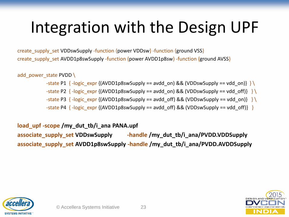
Integration with the Design UPF create_supply_set VDDswSupply -function {power VDDsw} -function {ground VSS}
create_supply_set AVDD1p8swSupply -function {power AVDD1p8sw} -function {ground AVSS}
add_power_state PVDD \
-state P1 { -logic_expr {(AVDD1p8swSupply == avdd_on) && (VDDswSupply == vdd_on)} } \
-state P2 { -logic_expr {(AVDD1p8swSupply == avdd_on) && (VDDswSupply == vdd_off)} } \
-state P3 { -logic_expr {(AVDD1p8swSupply == avdd_off) && (VDDswSupply == vdd_on)} } \
-state P4 { -logic_expr {(AVDD1p8swSupply == avdd_off) && (VDDswSupply == vdd_off)} }
load_upf -scope /my_dut_tb/i_ana PANA.upf
associate_supply_set VDDswSupply -handle /my_dut_tb/i_ana/PVDD.VDDSupply
associate_supply_set AVDD1p8swSupply -handle /my_dut_tb/i_ana/PVDD.AVDDSupply
© Accellera Systems Initiative 23
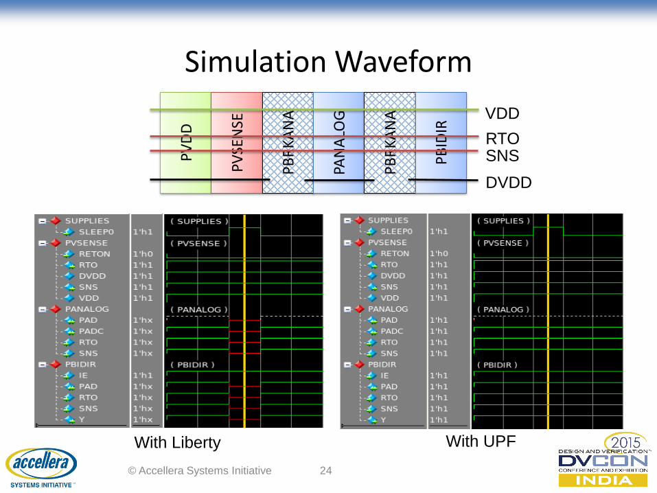
Simulation Waveform
© Accellera Systems Initiative 24
PV
DD
PV
SEN
SE
PB
RK
AN
A
PAN
ALO
G
PB
RK
AN
A
PB
IDIR
VDD
RTO SNS
DVDD
With Liberty With UPF
LIBRARY VALIDATION FLOW
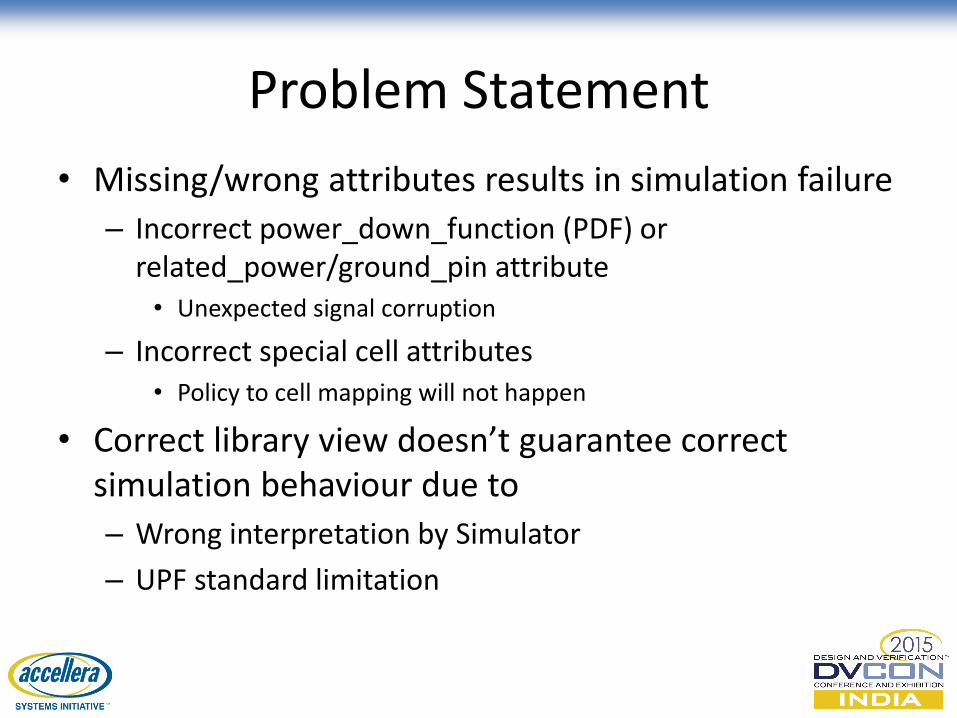
Problem Statement
• Missing/wrong attributes results in simulation failure
– Incorrect power_down_function (PDF) or related_power/ground_pin attribute • Unexpected signal corruption
– Incorrect special cell attributes • Policy to cell mapping will not happen
• Correct library view doesn’t guarantee correct simulation behaviour due to
– Wrong interpretation by Simulator
– UPF standard limitation
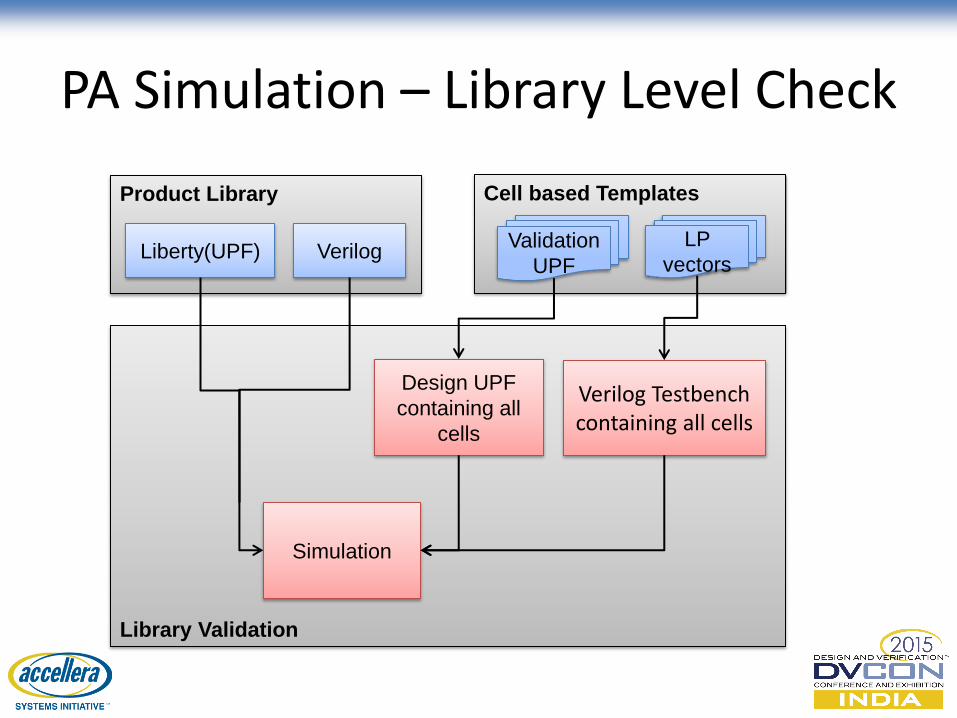
PA Simulation – Library Level Check
Library Validation
Cell based Templates
Validation
UPF
LP
vectors
Design UPF
containing all
cells
Verilog Testbench containing all cells
Product Library
Liberty(UPF) Verilog
Simulation
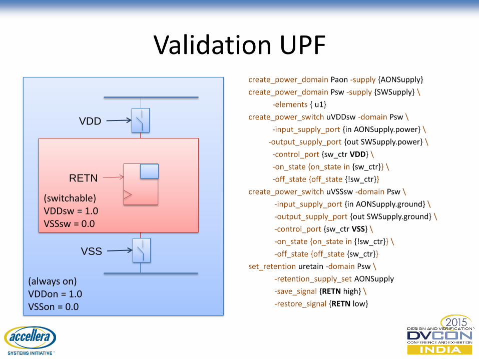
Validation UPF
create_power_domain Paon -supply {AONSupply}
create_power_domain Psw -supply {SWSupply} \
-elements { u1}
create_power_switch uVDDsw -domain Psw \
-input_supply_port {in AONSupply.power} \
-output_supply_port {out SWSupply.power} \
-control_port {sw_ctr VDD} \
-on_state {on_state in {sw_ctr}} \
-off_state {off_state {!sw_ctr}}
create_power_switch uVSSsw -domain Psw \
-input_supply_port {in AONSupply.ground} \
-output_supply_port {out SWSupply.ground} \
-control_port {sw_ctr VSS} \
-on_state {on_state in {!sw_ctr}} \
-off_state {off_state {sw_ctr}}
set_retention uretain -domain Psw \
-retention_supply_set AONSupply
-save_signal {RETN high} \
-restore_signal {RETN low}
(always on) VDDon = 1.0 VSSon = 0.0
VDD
VSS
(switchable) VDDsw = 1.0 VSSsw = 0.0
RETN
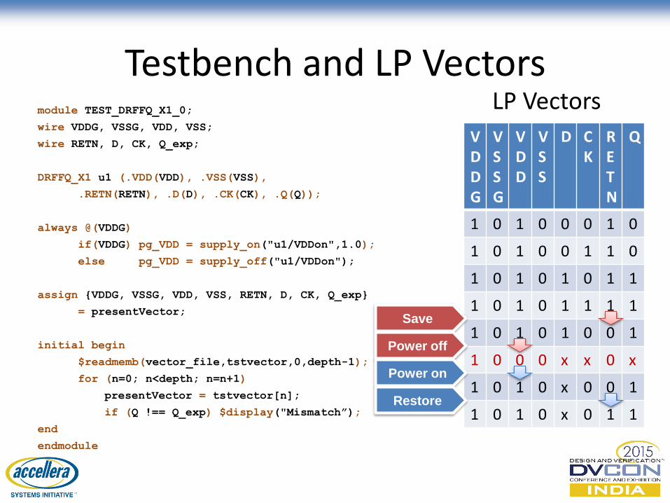
Testbench and LP Vectors LP Vectors
VDDG
VSSG
VDD
VSS
D CK
RETN
Q
1 0 1 0 0 0 1 0
1 0 1 0 0 1 1 0
1 0 1 0 1 0 1 1
1 0 1 0 1 1 1 1
1 0 1 0 1 0 0 1
1 0 0 0 x x 0 x
1 0 1 0 x 0 0 1
1 0 1 0 x 0 1 1
Save
Power off
Power on
Restore
module TEST_DRFFQ_X1_0;
wire VDDG, VSSG, VDD, VSS;
wire RETN, D, CK, Q_exp;
DRFFQ_X1 u1 (.VDD(VDD), .VSS(VSS),
.RETN(RETN), .D(D), .CK(CK), .Q(Q));
always @(VDDG)
if(VDDG) pg_VDD = supply_on("u1/VDDon",1.0);
else pg_VDD = supply_off("u1/VDDon");
assign {VDDG, VSSG, VDD, VSS, RETN, D, CK, Q_exp}
= presentVector;
initial begin
$readmemb(vector_file,tstvector,0,depth-1);
for (n=0; n<depth; n=n+1)
presentVector = tstvector[n];
if (Q !== Q_exp) $display("Mismatch”);
end
endmodule
Summary
• PA simulation is a very powerful way to check the design power requirement early in the implementation cycle
• PA simulation is still in early phase and with increasing complexity, more check points need to be put in place to catch issues
• Identified enhancements fix some of the quality holes in existing PA simulation flow
• Library validation flow enables ARM to carry out comprehensive verification of cell power aware behaviour, thereby ensuring seamless PA simulation flow for our partners
© Accellera Systems Initiative 30

Questions?
© Accellera Systems Initiative 31