Embed Size (px)
Citation preview

CHALLENGES OF FIRE WATER PUMPS INSTALLATION IN
SHALLOW WATERS
By: Elmer Revilla and Bernard Leong
Chevron ETC-Fire Protection Engineers
Design Opportunity
Fire water and jockey pumps installed in shallow waters face the challenges of taking in mud and silt during operation that could damage the pump and increase maintenance cost
Design Variables
• Sea water depth
• Silt mean particle size and density
• Fire water or jockey pump flow rates
CFD Analysis
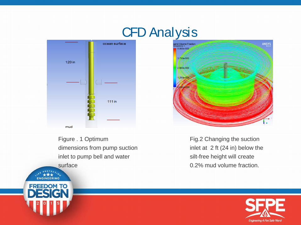
Figure . 1 Optimum dimensions from pump suction inlet to pump bell and water surface
Fig.2 Changing the suction inlet at 2 ft (24 in) below the silt-free height will create 0.2% mud volume fraction.
Physical Model Test Objective
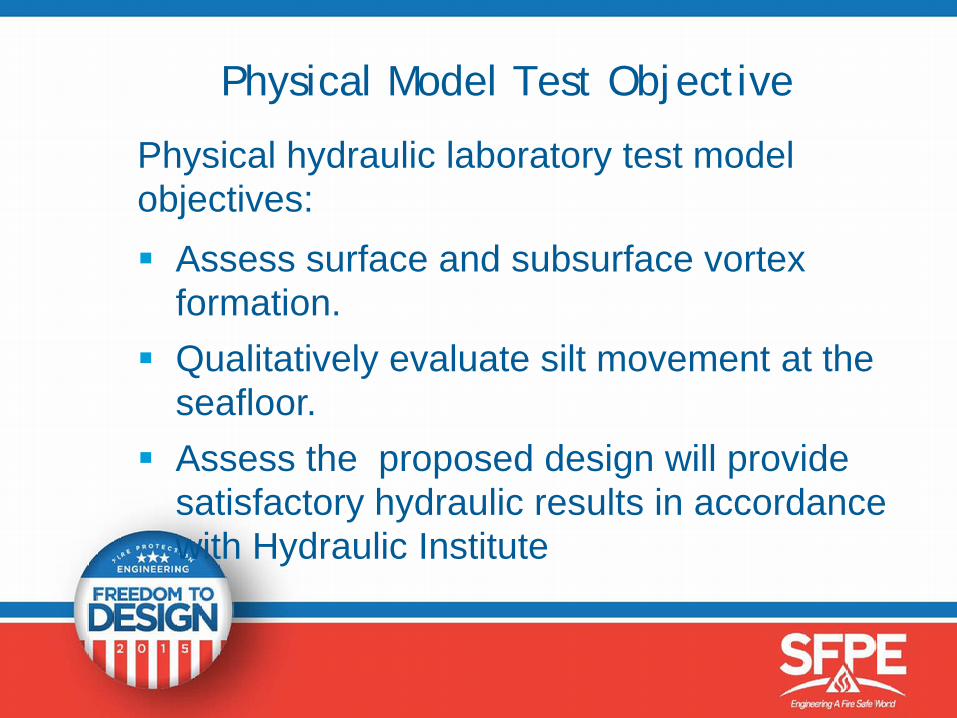
Physical hydraulic laboratory test model objectives: Assess surface and subsurface vortex
formation. Qualitatively evaluate silt movement at the
seafloor. Assess the proposed design will provide
satisfactory hydraulic results in accordance with Hydraulic Institute
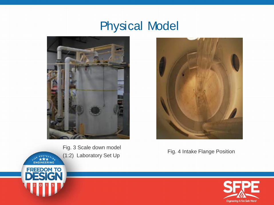
Physical Model
Fig. 3 Scale down model (1:2) Laboratory Set Up
Fig. 4 Intake Flange Position
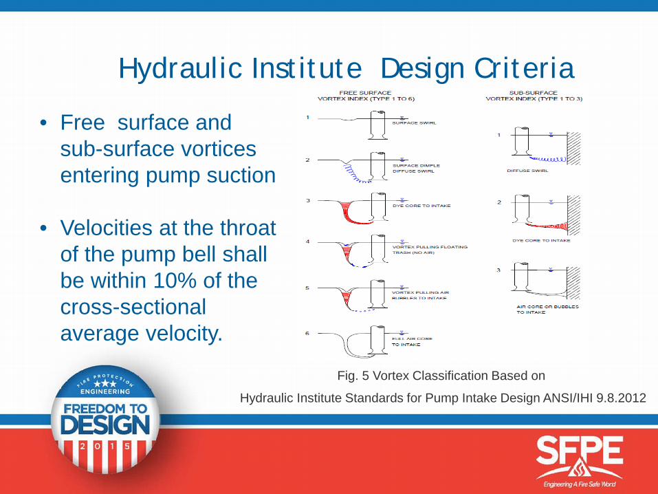
Hydraulic Institute Design Criteria
• Free surface and sub-surface vortices entering pump suction
• Velocities at the throat of the pump bell shall be within 10% of the cross-sectional average velocity.
Fig. 5 Vortex Classification Based on
Hydraulic Institute Standards for Pump Intake Design ANSI/IHI 9.8.2012
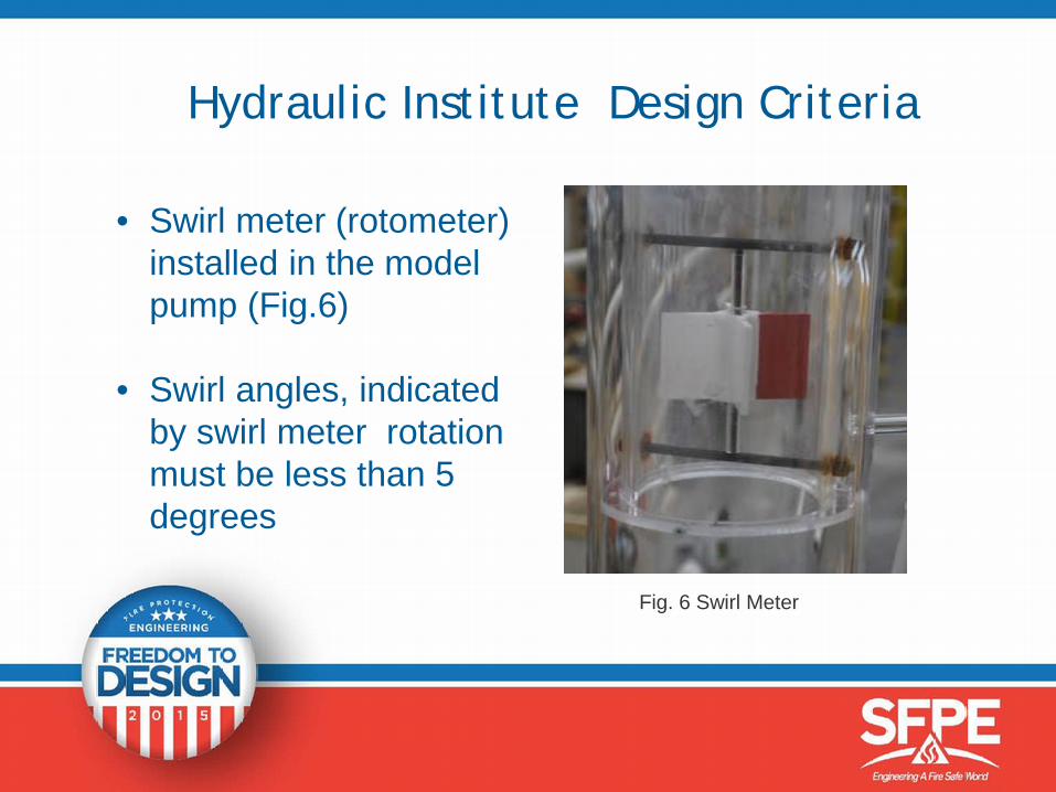
Hydraulic Institute Design Criteria
• Swirl meter (rotometer) installed in the model pump (Fig.6)
• Swirl angles, indicated by swirl meter rotation must be less than 5 degrees
Fig. 6 Swirl Meter
Conclusions
• Pump Can with two side inlets satisfied the research objective.
• Flow pre-swirl, surface and sub-surface vortex activity and velocities met the specified Hydraulic Institute(ANSI/IHI 9.8.2012) acceptance criteria.
Acknowledgements
• Peerless Pump/Grundfos PumpBrookshire,Texas
• Northwest Hydraulic ConsultantsEdmonton,Canada

Use of antifreeze solutions in fire protection systems
Jeffrey Rosen, CFEI
Exponent Inc. 13
Outline• Background
• Code requirements for antifreeze solutions
• Water mist system with antifreeze testing
• Discharge ignition criteria of antifreeze solutions
• Decision model for suitability of antifreeze solution in fire protection systems
14
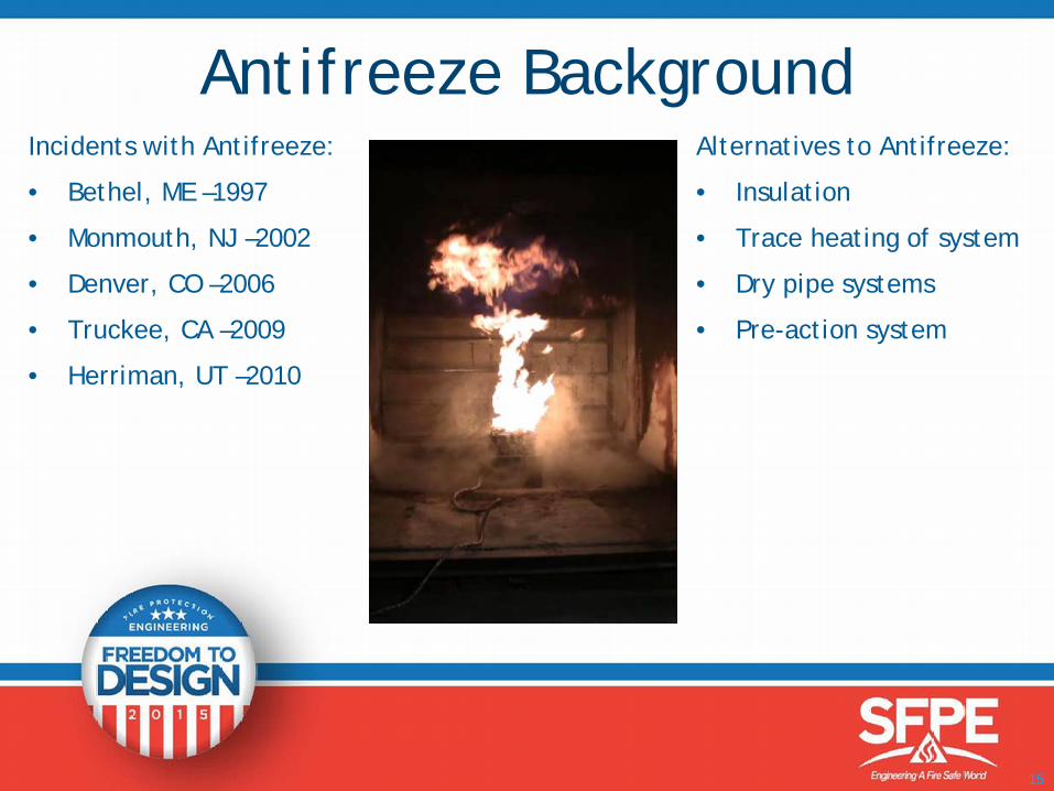
Incidents with Antifreeze:
• Bethel, ME –1997
• Monmouth, NJ –2002
• Denver, CO –2006
• Truckee, CA –2009
• Herriman, UT –2010
Alternatives to Antifreeze:
• Insulation
• Trace heating of system
• Dry pipe systems
• Pre-action system
15
Antifreeze Background
16
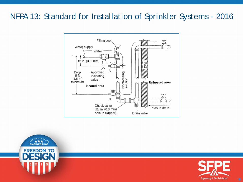
NFPA 13: Standard for Installation of Sprinkler Systems - 2016
17
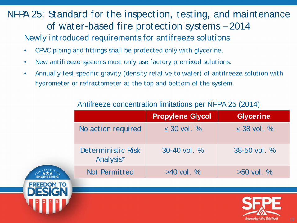
NFPA 25: Standard for the inspection, testing, and maintenance of water-based fire protection systems – 2014
Newly introduced requirements for antifreeze solutions• CPVC piping and fittings shall be protected only with glycerine.
• New antifreeze systems must only use factory premixed solutions.
• Annually test specific gravity (density relative to water) of antifreeze solution with hydrometer or refractometer at the top and bottom of the system.
*Demonstrate heat release rates of design fires
Propylene Glycol Glycerine
No action required ≤ 30 vol. % ≤ 38 vol. %
Deterministic Risk Analysis*
30-40 vol. % 38-50 vol. %
Not Permitted >40 vol. % >50 vol. %
Antifreeze concentration limitations per NFPA 25 (2014)
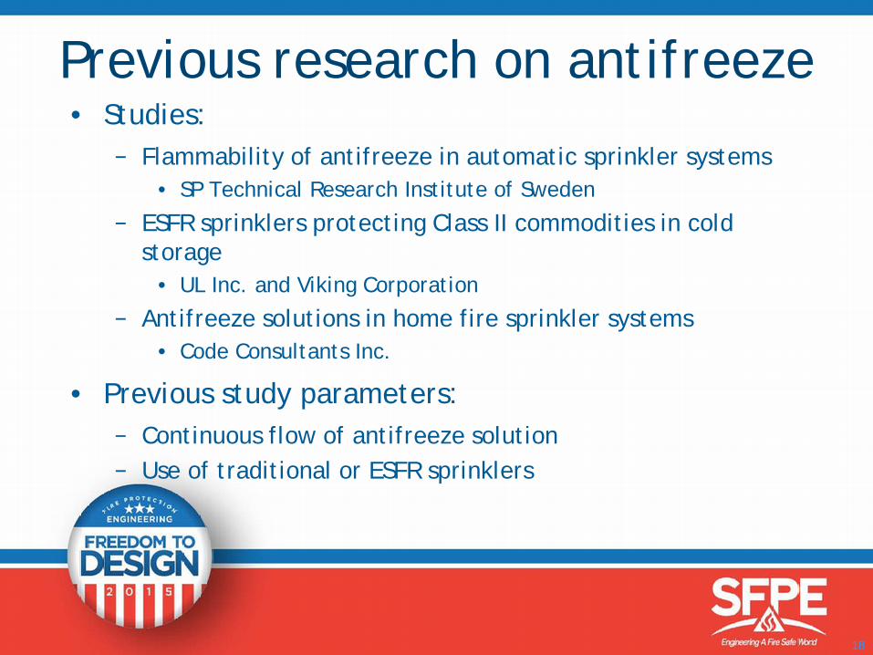
• Studies:− Flammability of antifreeze in automatic sprinkler systems
• SP Technical Research Institute of Sweden
− ESFR sprinklers protecting Class II commodities in cold storage
• UL Inc. and Viking Corporation
− Antifreeze solutions in home fire sprinkler systems• Code Consultants Inc.
• Previous study parameters:− Continuous flow of antifreeze solution− Use of traditional or ESFR sprinklers
18
Previous research on antifreeze
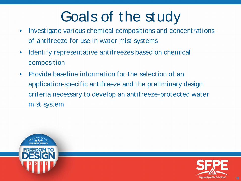
• Investigate various chemical compositions and concentrations of antifreeze for use in water mist systems
• Identify representative antifreezes based on chemical composition
• Provide baseline information for the selection of an application-specific antifreeze and the preliminary design criteria necessary to develop an antifreeze-protected water mist system
19
Goals of the study
20
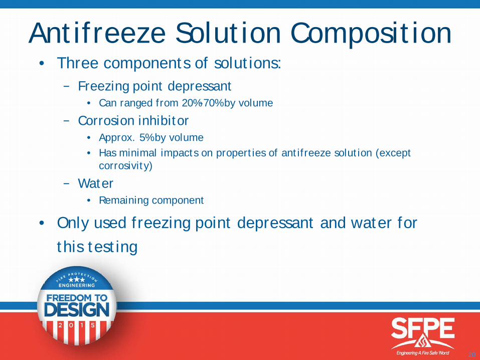
Antifreeze Solution Composition• Three components of solutions:
− Freezing point depressant• Can ranged from 20%-70% by volume
− Corrosion inhibitor• Approx. 5% by volume• Has minimal impacts on properties of antifreeze solution (except
corrosivity)
− Water• Remaining component
• Only used freezing point depressant and water for this testing
21
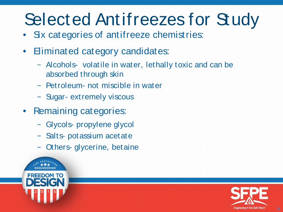
Selected Antifreezes for Study• Six categories of antifreeze chemistries:
• Eliminated category candidates:− Alcohols- volatile in water, lethally toxic and can be
absorbed through skin− Petroleum- not miscible in water− Sugar- extremely viscous
• Remaining categories:− Glycols- propylene glycol− Salts- potassium acetate− Others- glycerine, betaine
22
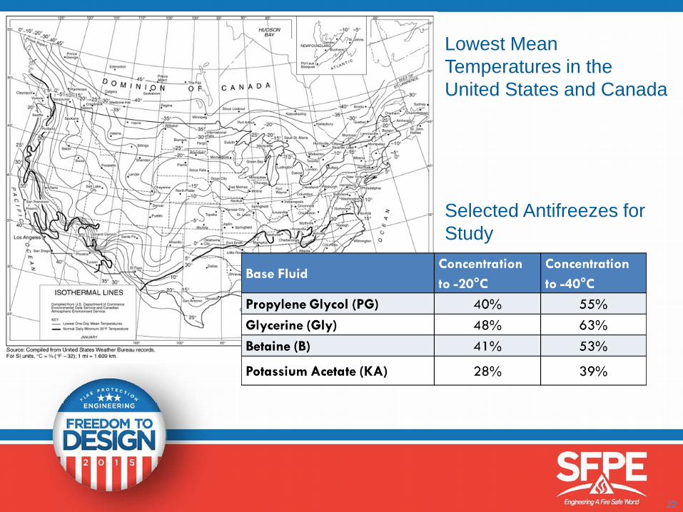
Lowest Mean Temperatures in the United States and Canada
Selected Antifreezes for Study
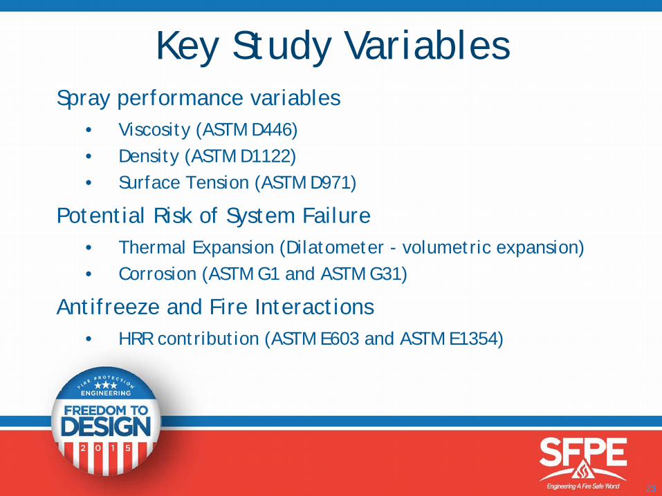
Spray performance variables• Viscosity (ASTM D446)• Density (ASTM D1122)• Surface Tension (ASTM D971)
Potential Risk of System Failure• Thermal Expansion (Dilatometer - volumetric expansion)• Corrosion (ASTM G1 and ASTM G31)
Antifreeze and Fire Interactions• HRR contribution (ASTM E603 and ASTM E1354)
23
Key Study Variables
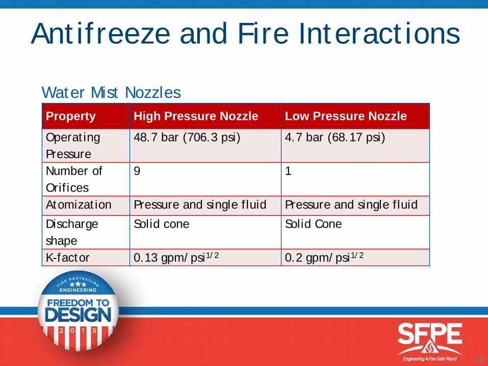
Water Mist Nozzles
24
Property High Pressure Nozzle Low Pressure NozzleOperating Pressure
48.7 bar (706.3 psi) 4.7 bar (68.17 psi)
Number of Orifices
9 1
Atomization Pressure and single fluid Pressure and single fluid
Discharge shape
Solid cone Solid Cone
K-factor 0.13 gpm/psi1/2 0.2 gpm/psi1/2
Antifreeze and Fire Interactions
25
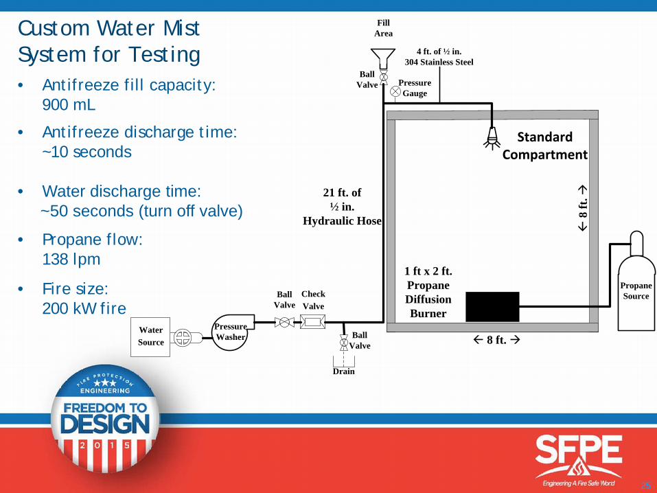
4 ft. of ½ in. 304 Stainless Steel
BallValve
Propane Source
Pressure Washer
Check Valve
Water Source
Ball Valve
Drain
BallValve
FillArea
Pressure Gauge
1 ft x 2 ft.Propane Diffusion Burner
ß 8
ft. à
ß 8 ft. à
21 ft. of ½ in.
Hydraulic Hose
Standard Compartment
Custom Water Mist System for Testing• Antifreeze fill capacity:
900 mL
• Antifreeze discharge time:~10 seconds
• Water discharge time:~50 seconds (turn off valve)
• Propane flow:138 lpm
• Fire size:200 kW fire
26
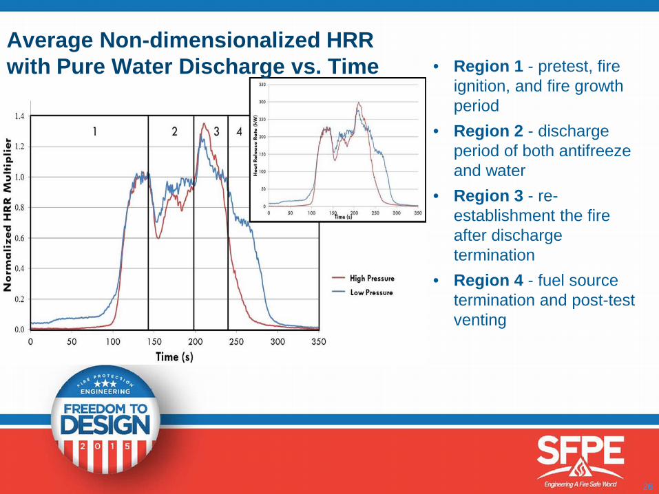
• Region 1 - pretest, fire ignition, and fire growth period
• Region 2 - discharge period of both antifreeze and water
• Region 3 - re-establishment the fire after discharge termination
• Region 4 - fuel source termination and post-test venting
Average Non-dimensionalized HRR with Pure Water Discharge vs. Time
27
High Pressure Test Videos
28
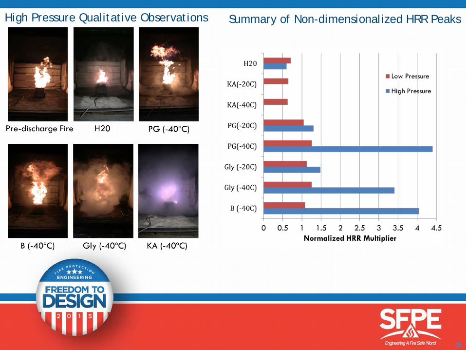
High Pressure Qualitative Observations Summary of Non-dimensionalized HRR Peaks

29
Addition of antifreeze to water resulted in (all cases):• Increases in viscosity (larger droplets)• Increases in density (smaller droplets)• Decreases in surface tension (smaller droplets)
Increases in pressure also creates smaller droplets
• No droplet image analysis – quantities effect unknown how the properties impact droplet size between antifreezes and concentrations
• Visual droplet size difference between high and low pressure• Viscosity would become dominant property as temperature decreases
which would increase the droplet size
Spray performance - Opposing Effects
30
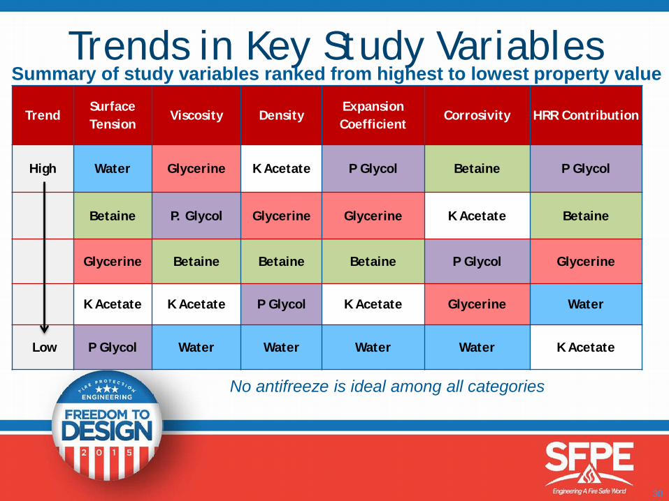
Trends in Key Study VariablesTrend
Surface Tension
Viscosity DensityExpansion Coefficient
Corrosivity HRR Contribution
High Water Glycerine K Acetate P Glycol Betaine P Glycol
Betaine P. Glycol Glycerine Glycerine K Acetate Betaine
Glycerine Betaine Betaine Betaine P Glycol Glycerine
K Acetate K Acetate P Glycol K Acetate Glycerine Water
Low P Glycol Water Water Water Water K Acetate
Summary of study variables ranked from highest to lowest property value
No antifreeze is ideal among all categories
31
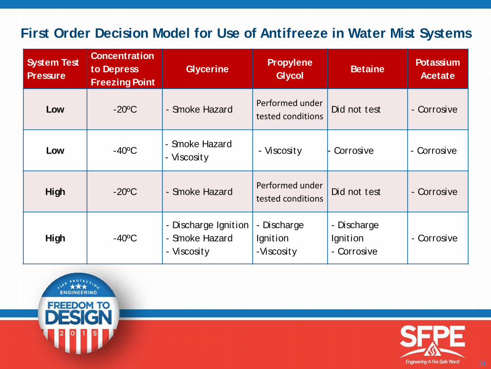
First Order Decision Model for Use of Antifreeze in Water Mist Systems
System Test Pressure
Concentration to DepressFreezing Point
GlycerinePropylene
GlycolBetaine
Potassium Acetate
Low -20ºC - Smoke HazardPerformed under tested conditions
Did not test - Corrosive
Low -40ºC- Smoke Hazard- Viscosity
- Viscosity - Corrosive - Corrosive
High -20ºC - Smoke HazardPerformed under tested conditions
Did not test - Corrosive
High -40ºC- Discharge Ignition- Smoke Hazard- Viscosity
- Discharge Ignition-Viscosity
- Discharge Ignition- Corrosive
- Corrosive
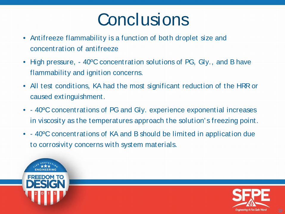
• Antifreeze flammability is a function of both droplet size and concentration of antifreeze
• High pressure, - 40ºC concentration solutions of PG, Gly., and B have flammability and ignition concerns.
• All test conditions, KA had the most significant reduction of the HRR or caused extinguishment.
• - 40ºC concentrations of PG and Gly. experience exponential increases in viscosity as the temperatures approach the solution’s freezing point.
• - 40ºC concentrations of KA and B should be limited in application due to corrosivity concerns with system materials.
32
Conclusions
• Professor Kathy Notarianni, WPI Fire Protection Engineering
• Project partners:
− Michael Szkutak− Stephen Jaskolka− Matthew Connolly
33
Acknowledgements
Use of antifreeze solutions in fire protection systems
Jeffrey Rosen, CFEI
Exponent Inc. 34Work performed at WPI

FIRE PROTECTION ENGINEERING
OF
FIRE STANDPIPE FOR BRIDGES
INTRODUCTION ENGINEERINGBRIDGE STRUCTURE - PROJECT TEAM
CODES & STANDARDS - SAFETY ISSUES
FIRE STANDPIPE ENGINEERING
ENVIRONMENTAL ISSUES
COMMISSIONING - KEY TAKE AWAY
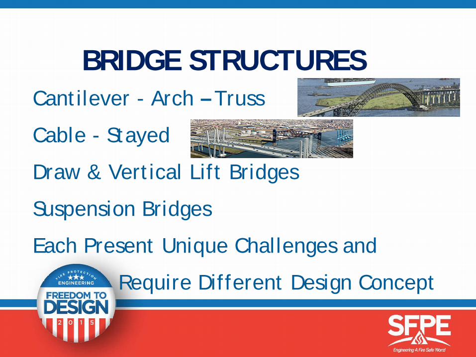
BRIDGE STRUCTURES Cantilever - Arch – Truss
Cable - Stayed
Draw & Vertical Lift Bridges
Suspension Bridges
Each Present Unique Challenges and
Require Different Design Concept
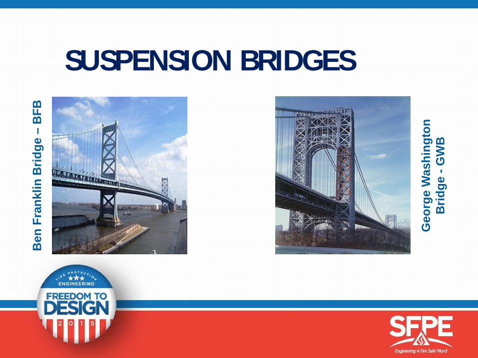
SUSPENSION BRIDGES
Geo
rge
Was
hing
ton
Brid
ge -
GW
B
Ben
Fra
nklin
Brid
ge –
BFB
GWB–REFERENCED DATA
14 Lanes of Traffic, 8 Upper, 6 Lower Decks
Bridge is 4,760 Feet Long – Width 119 Feet
Center Span 3,500 Feet Tower to Tower
Upper Level - Pedestrians and Bicycles
Fire Standpipe (FSP) System
STAKEHOLDERS
Owner - Agency – AHJ - First Responder, Facility Maintenance - State Highway DOT, Local Fire Marshall, Insurance Underwriters - United States Army Corps of Engineers-USACE & US Coast Guard
PROJECT TEAMFire Protection, Plumbing, Mechanical
Electrical, Structural, Materials, Traffic,
Civil, Environmental, Architecture,
Construction Management, Estimating
Project Management, Facility Personnel.
CODES & NFPA STANDARDSBuilding, Fire Codes(FC) and Local Regulations
NFPA 502–Standard for Road Tunnels, Bridges and Other Limited Access Highways (NYC-FC:2011Edition)
NFPA 13 – Installation of Sprinkler Systems
NFPA 14 – Installation of Standpipe and Hose Systems
CODES & NFPA STANDARDSNFPA 20 – Stationary Pumps for Fire Protection
NFPA 24 – Private Fire Service Mains and their Appurtenances
NFPA 25– Inspection Testing and Maintenance of Water Based fire Protection
NFPA 70 – N.E.C & NFPA 72 – Fire Alarm Code
OSHA & DEP- Regulations
SAFETY REQUIREMENTS
Safety – Briefing, Training, Shoes and Vest.
Fall Protection - Safety Harness required.
Traffic - Lane Closures Required For Piping System Survey and Night Time hrs.
Weather - Service Walkway, Icy & Slippery.
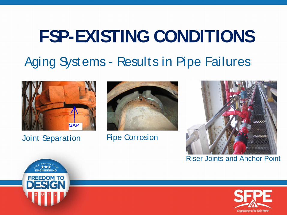
FSP-EXISTING CONDITIONSAging Systems - Results in Pipe Failures
Joint Separation Pipe Corrosion
Riser Joints and Anchor Point
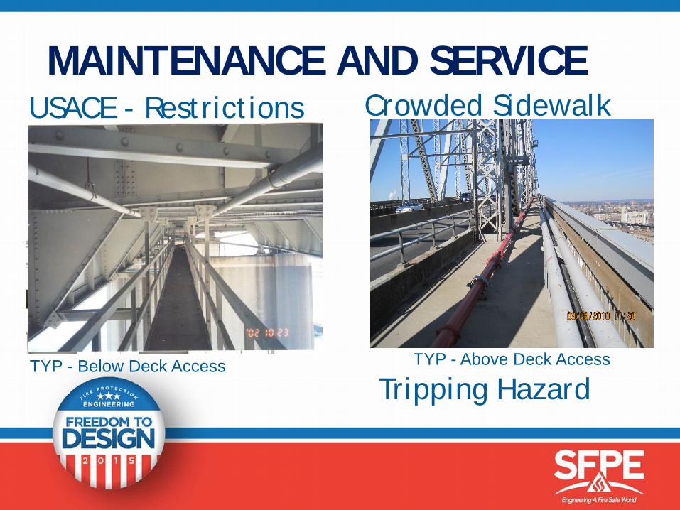
MAINTENANCE AND SERVICE
TYP - Above Deck Access TYP - Below Deck Access
USACE - Restrictions Crowded Sidewalk
Tripping Hazard
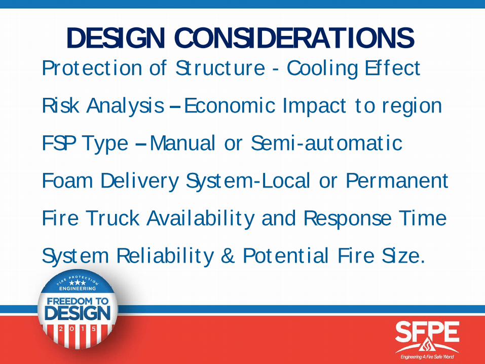
DESIGN CONSIDERATIONS Protection of Structure - Cooling Effect
Risk Analysis – Economic Impact to region
FSP Type – Manual or Semi-automatic
Foam Delivery System-Local or Permanent
Fire Truck Availability and Response Time
System Reliability & Potential Fire Size.
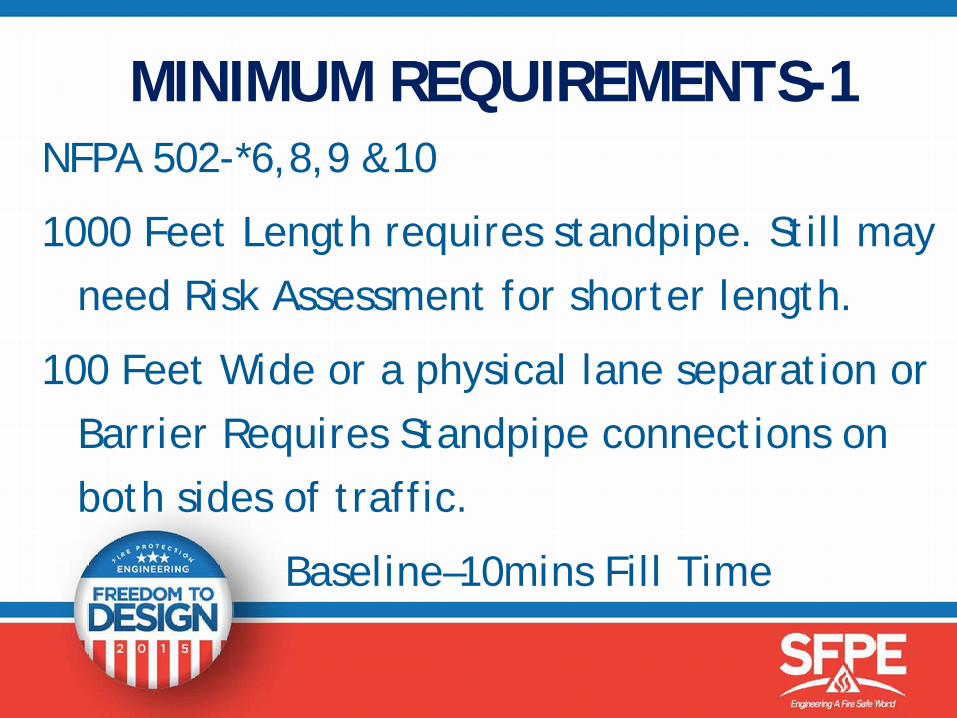
MINIMUM REQUIREMENTS-1NFPA 502-*6,8,9 &10
1000 Feet Length requires standpipe. Still may need Risk Assessment for shorter length.
100 Feet Wide or a physical lane separation or Barrier Requires Standpipe connections on both sides of traffic.
Baseline–10mins Fill Time
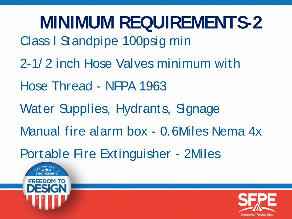
MINIMUM REQUIREMENTS-2Class I Standpipe 100psig min
2-1/2 inch Hose Valves minimum with
Hose Thread - NFPA 1963
Water Supplies, Hydrants, Signage
Manual fire alarm box - 0.6Miles Nema 4x
Portable Fire Extinguisher - 2Miles
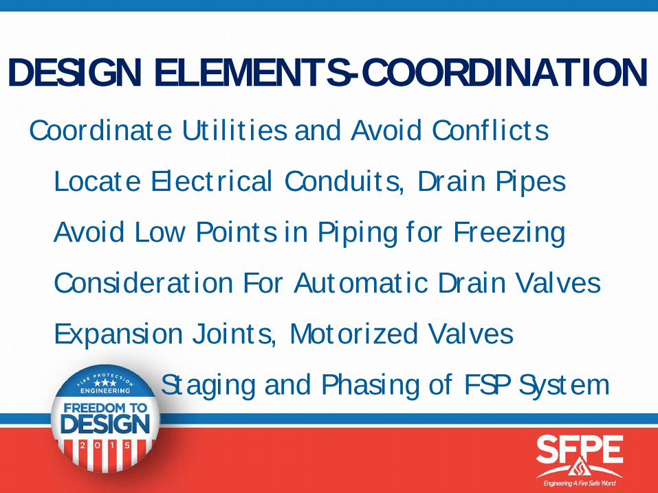
DESIGN ELEMENTS-COORDINATION Coordinate Utilities and Avoid Conflicts
Locate Electrical Conduits, Drain Pipes
Avoid Low Points in Piping for Freezing
Consideration For Automatic Drain Valves
Expansion Joints, Motorized Valves
Staging and Phasing of FSP System

SYSTEM CHALLENGES - 1 Identify FSP Location, Options and Evaluate: Location of FDC Siamese, size and length of
standpipe to furthest Hose Valve. Hose Valves – Spacing -275ft(NYC-FC 200ft) and
Drainage RequirementsUse of sectional valves to minimize pipe fill timesAdvantages of pipe loops on larger bridges with
sectional valves to increase system reliability
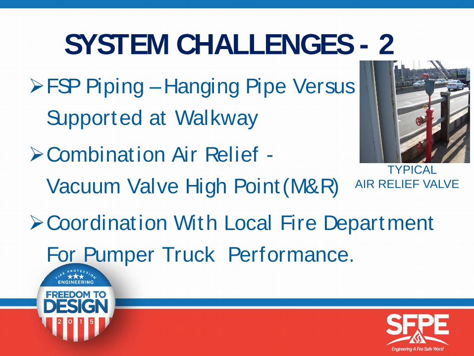
SYSTEM CHALLENGES - 2 FSP Piping – Hanging Pipe Versus
Supported at Walkway
Combination Air Relief -Vacuum Valve High Point(M&R)
Coordination With Local Fire Department For Pumper Truck Performance.
TYPICAL AIR RELIEF VALVE
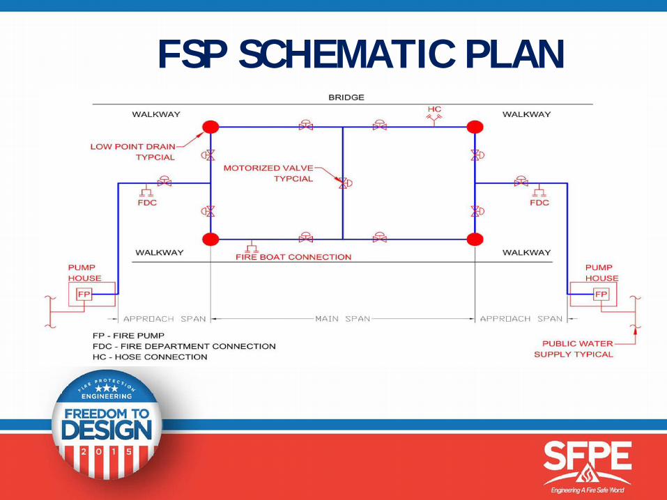
FSP SCHEMATIC PLAN
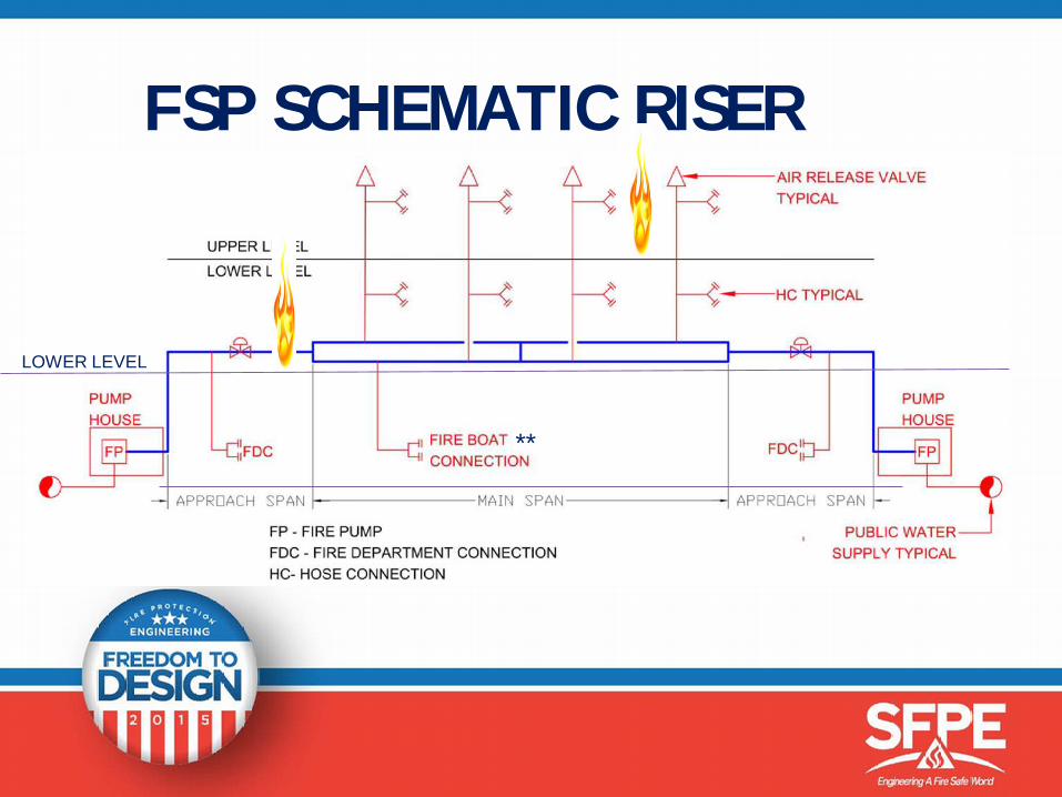
FSP SCHEMATIC RISER
LOWER LEVEL
**
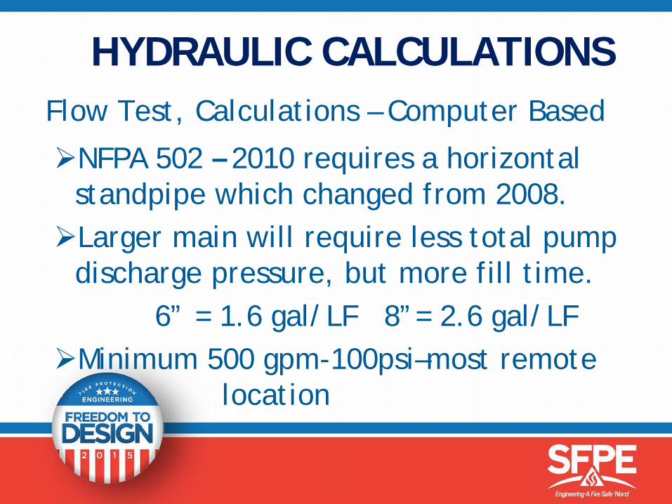
Flow Test, Calculations – Computer Based
NFPA 502 – 2010 requires a horizontal standpipe which changed from 2008.Larger main will require less total pump
discharge pressure, but more fill time. 6” = 1.6 gal/LF 8”= 2.6 gal/LF
Minimum 500 gpm-100psi–most remote location
HYDRAULIC CALCULATIONS
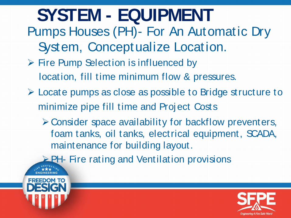
SYSTEM - EQUIPMENTPumps Houses (PH)- For An Automatic Dry
System, Conceptualize Location. Fire Pump Selection is influenced by
location, fill time minimum flow & pressures.
Locate pumps as close as possible to Bridge structure to minimize pipe fill time and Project Costs
Consider space availability for backflow preventers, foam tanks, oil tanks, electrical equipment, SCADA, maintenance for building layout.
PH- Fire rating and Ventilation provisions
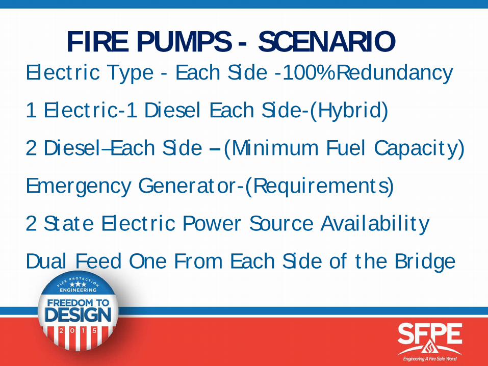
FIRE PUMPS - SCENARIOElectric Type - Each Side -100% Redundancy
1 Electric-1 Diesel Each Side-(Hybrid)
2 Diesel–Each Side – (Minimum Fuel Capacity)
Emergency Generator-(Requirements)
2 State Electric Power Source Availability
Dual Feed One From Each Side of the Bridge
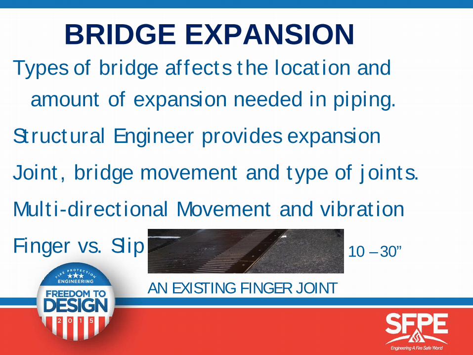
BRIDGE EXPANSIONTypes of bridge affects the location and
amount of expansion needed in piping.
Structural Engineer provides expansion
Joint, bridge movement and type of joints.
Multi-directional Movement and vibration
Finger vs. Slip
AN EXISTING FINGER JOINT
10 – 30”
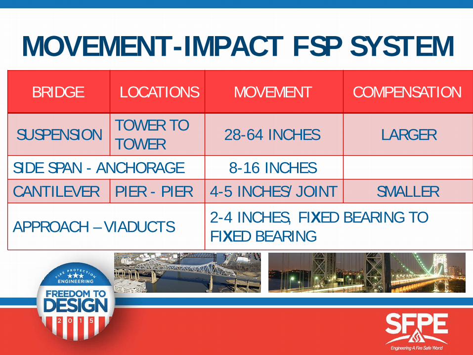
MOVEMENT-IMPACT FSP SYSTEMBRIDGE LOCATIONS MOVEMENT COMPENSATION
SUSPENSION TOWER TO TOWER 28-64 INCHES LARGER
SIDE SPAN - ANCHORAGE 8-16 INCHESCANTILEVER PIER - PIER 4-5 INCHES/JOINT SMALLER
APPROACH – VIADUCTS 2-4 INCHES, FIXED BEARING TO FIXED BEARING
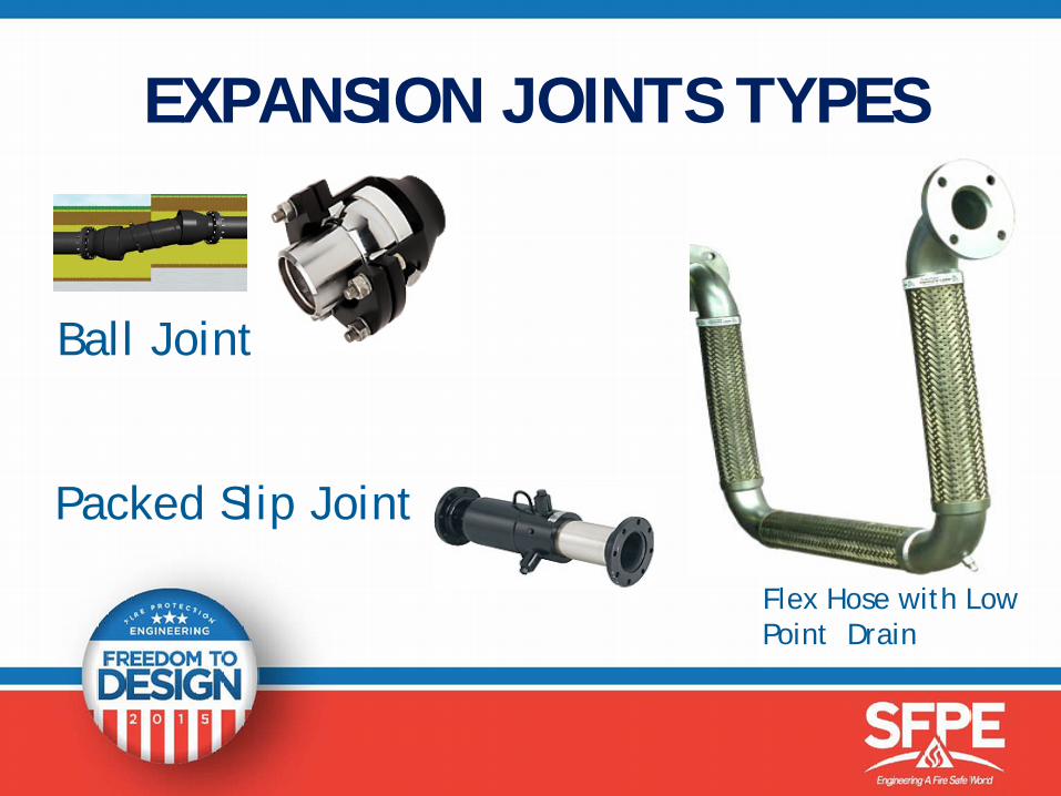
EXPANSION JOINTS TYPES
Ball Joint
Packed Slip Joint
Flex Hose with Low Point Drain
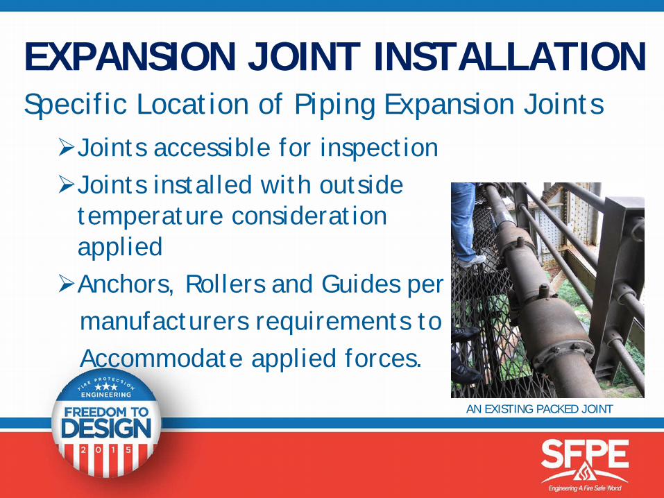
EXPANSION JOINT INSTALLATIONSpecific Location of Piping Expansion JointsJoints accessible for inspectionJoints installed with outside
temperature consideration applied Anchors, Rollers and Guides per
manufacturers requirements toAccommodate applied forces.
AN EXISTING PACKED JOINT
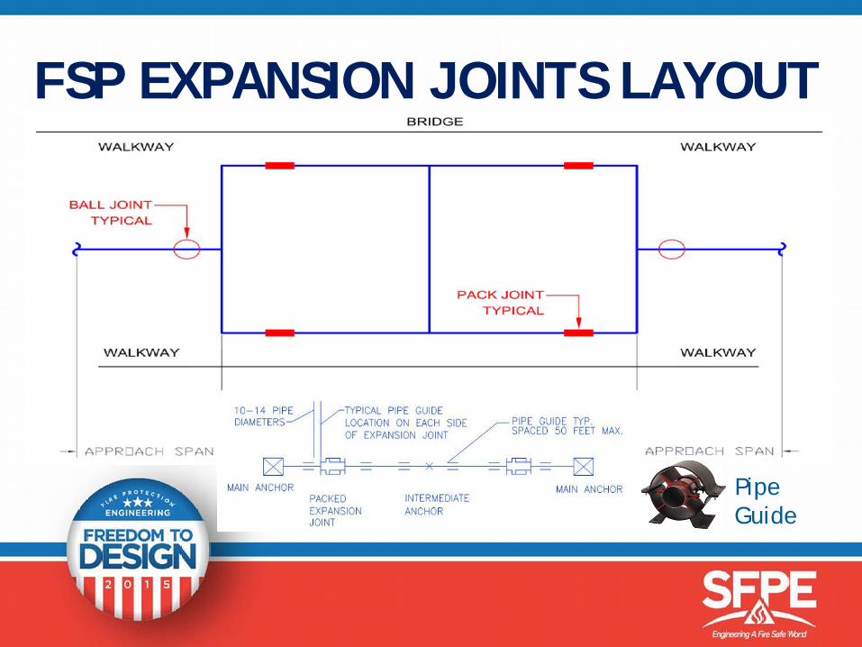
FSP EXPANSION JOINTS LAYOUT
Pipe Guide
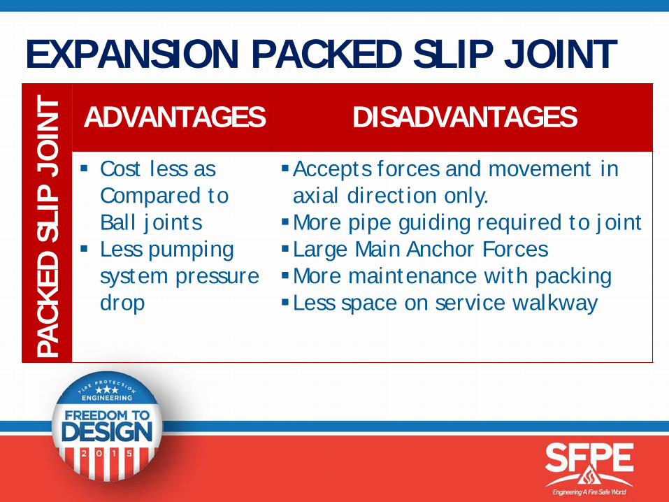
EXPANSION PACKED SLIP JOINTPA
CKED
SLIP
JOIN
T ADVANTAGES DISADVANTAGES
Cost less as Compared to Ball joints
Less pumping system pressure drop
Accepts forces and movement in axial direction only. More pipe guiding required to jointLarge Main Anchor ForcesMore maintenance with packingLess space on service walkway
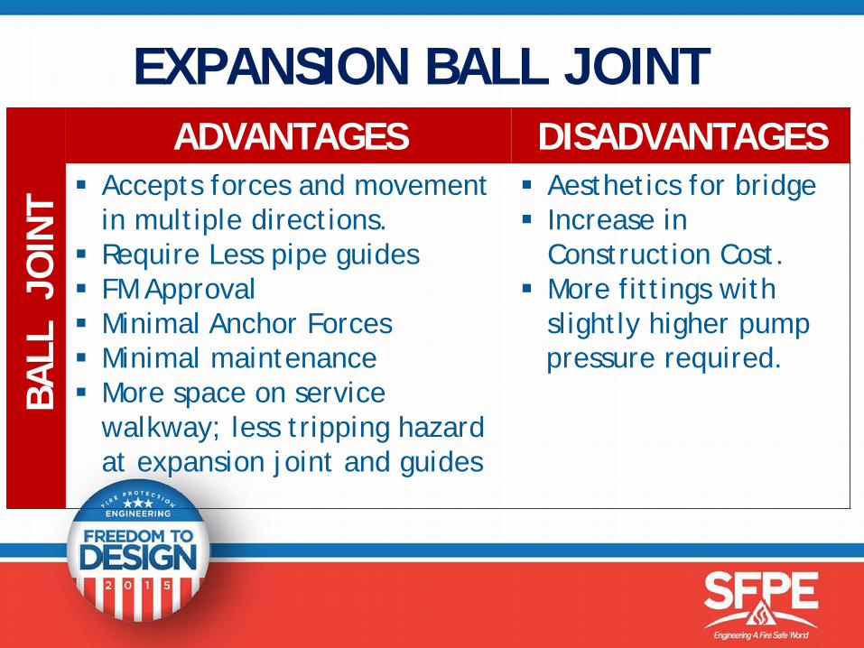
EXPANSION BALL JOINTBA
LL J
OIN
T
ADVANTAGES DISADVANTAGES Accepts forces and movement
in multiple directions. Require Less pipe guides FM Approval Minimal Anchor Forces Minimal maintenance More space on service
walkway; less tripping hazard at expansion joint and guides
Aesthetics for bridge Increase in
Construction Cost. More fittings with
slightly higher pump pressure required.
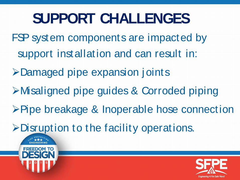
SUPPORT CHALLENGESFSP system components are impacted by support installation and can result in:
Damaged pipe expansion joints
Misaligned pipe guides & Corroded piping
Pipe breakage & Inoperable hose connection
Disruption to the facility operations.
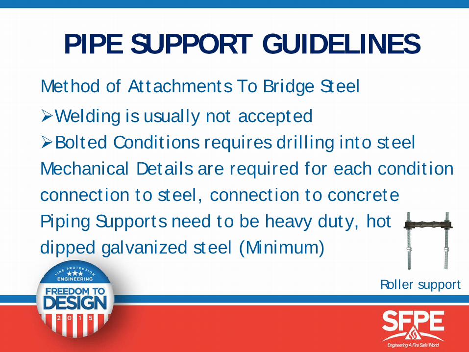
PIPE SUPPORT GUIDELINESMethod of Attachments To Bridge Steel
Welding is usually not acceptedBolted Conditions requires drilling into steelMechanical Details are required for each conditionconnection to steel, connection to concrete Piping Supports need to be heavy duty, hot dipped galvanized steel (Minimum)
Roller support
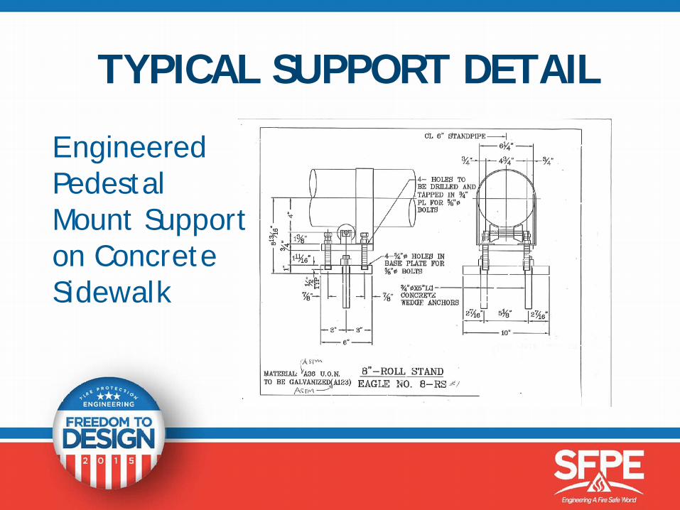
TYPICAL SUPPORT DETAIL
EngineeredPedestalMount Supporton ConcreteSidewalk

AIR VENTING
Air collects at High Points Air pockets create restriction in flow Air can eventually stop flow all together or Part of Air Pocket will break away creating
surge in piping and causing damage
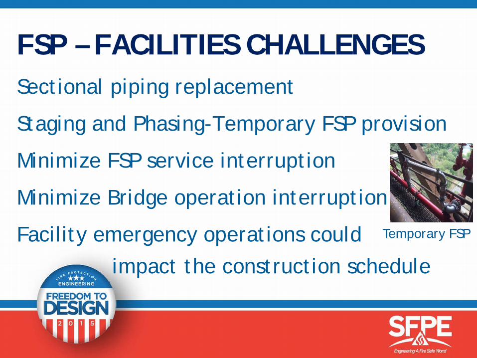
FSP – FACILITIES CHALLENGESSectional piping replacement
Staging and Phasing-Temporary FSP provision
Minimize FSP service interruption
Minimize Bridge operation interruption
Facility emergency operations could impact the construction schedule
Temporary FSP
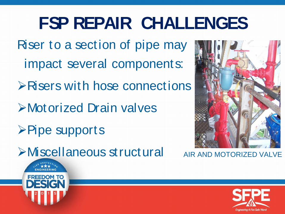
FSP REPAIR CHALLENGESRiser to a section of pipe may impact several components:
Risers with hose connections
Motorized Drain valves
Pipe supports
Miscellaneous structural AIR AND MOTORIZED VALVE
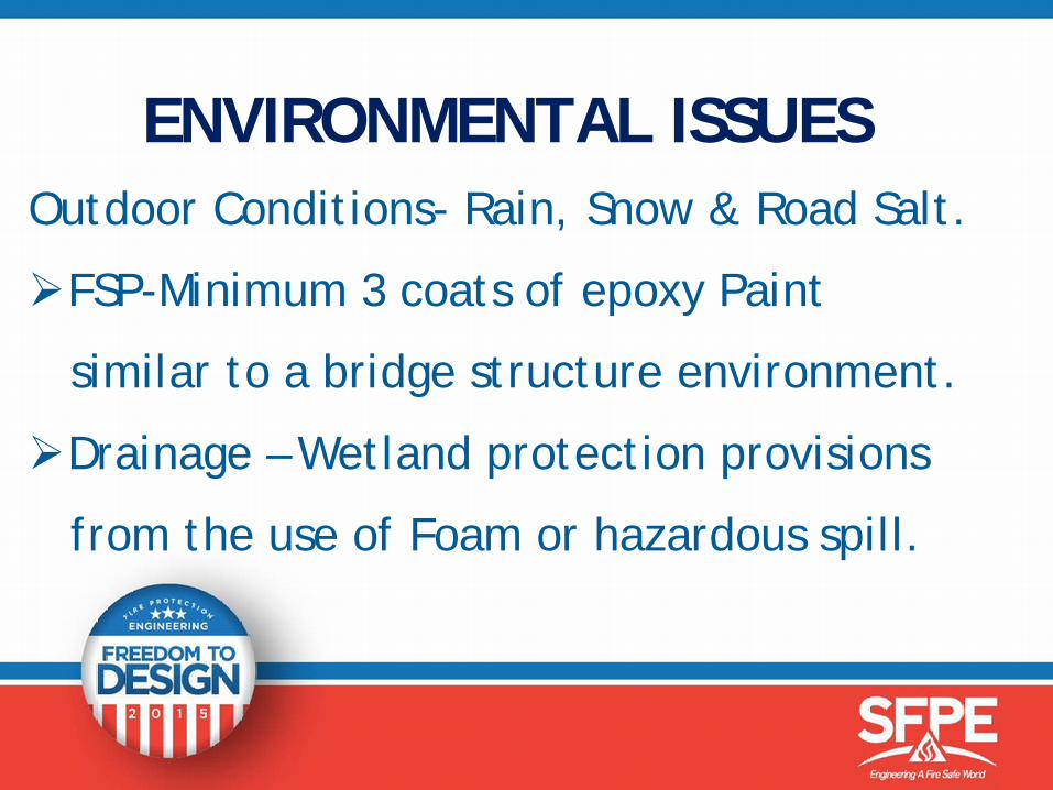
ENVIRONMENTAL ISSUES Outdoor Conditions- Rain, Snow & Road Salt.
FSP-Minimum 3 coats of epoxy Paint
similar to a bridge structure environment.
Drainage – Wetland protection provisions
from the use of Foam or hazardous spill.
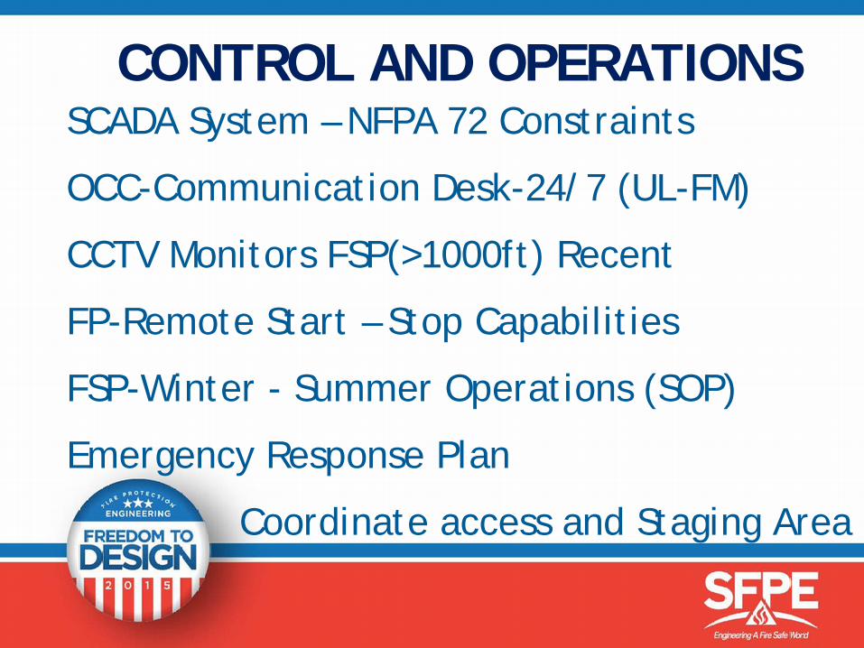
CONTROL AND OPERATIONSSCADA System – NFPA 72 Constraints
OCC-Communication Desk-24/7 (UL-FM)
CCTV Monitors FSP(>1000ft) Recent
FP-Remote Start – Stop Capabilities
FSP-Winter - Summer Operations (SOP)
Emergency Response Plan
Coordinate access and Staging Area
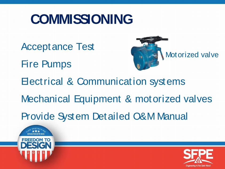
COMMISSIONING
Acceptance Test
Fire Pumps
Electrical & Communication systems
Mechanical Equipment & motorized valves
Provide System Detailed O&M Manual
Motorized valve
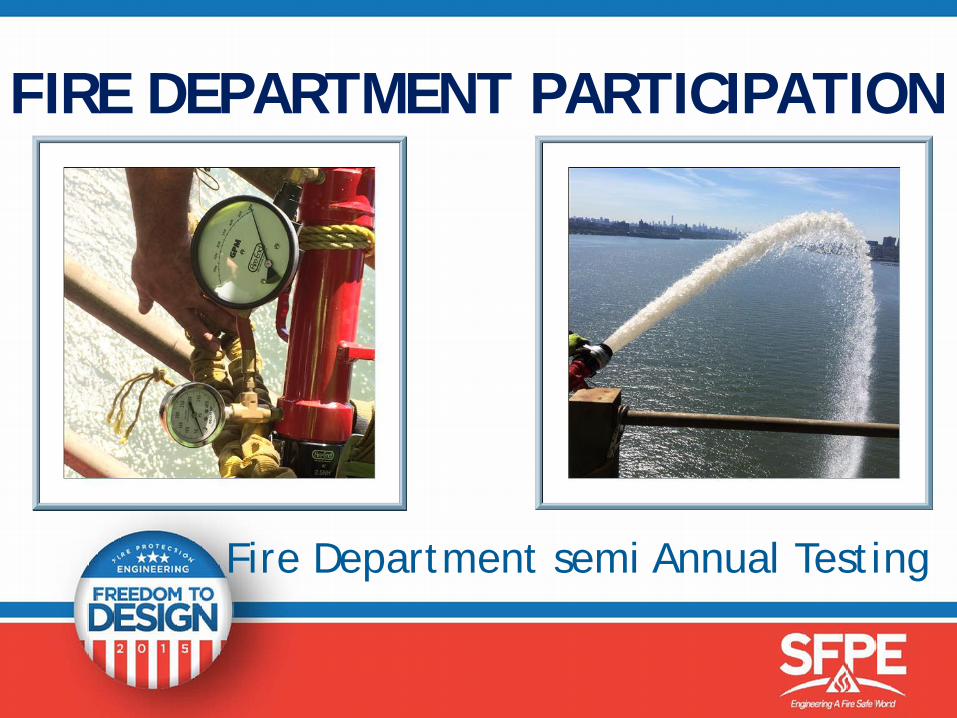
FIRE DEPARTMENT PARTICIPATION
Fire Department semi Annual Testing
SUMMARY OF BRIDGE FSP Adhere to safety procedures
Establish Basis of Design and think outside
the box. (Above Minimum NFPA 502 Standards)
Establish Minimum Design Criteria Maintain
System Reliability and Redundancy
Confirm First Responders and Coordinate–AHJ
FSP - KEY TAKE AWAYMaintain Adequate Fire Protection and provide
FSP State of readiness to:
Ensure Life Safety and minimized damages, Mitigate Structural Damage and Prevent progressive Structural Collapse, Minimize Economic Impact and Coordinate with stake
holders
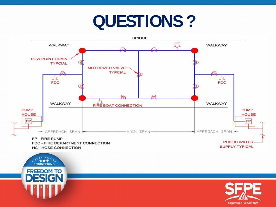
QUESTIONS ?

THANK YOU ALL!