Embed Size (px)
Citation preview
Practical Experience with CEMS Measurement
Challenges Associated with making:
ReliableBelievable
CONTINUOUS
Flow Measurements in Large Utility Stacks

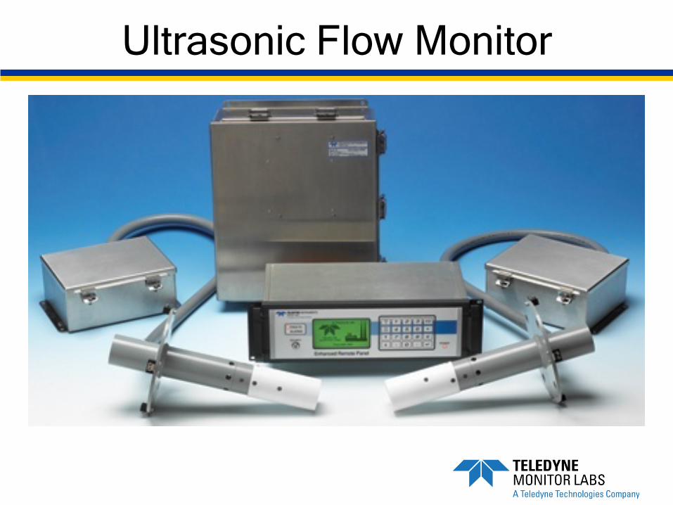
Ultrasonic Flow Monitor
Overview
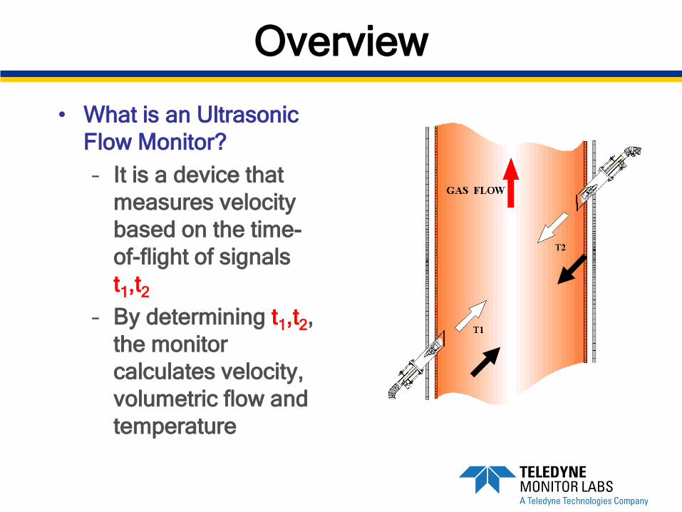
• What is an Ultrasonic Flow Monitor?– It is a device that
measures velocity based on the time-of-flight of signals t1,t2
– By determining t1,t2, the monitor calculates velocity, volumetric flow and temperature

Stack Geometry
• L = PathlengthTransducer to Transducer
• H = Offset
• Area = Cross Sectional Area
• θ= Angle; <45°STACK OFFSET
Area
θ
RELIABILITY CONCERNS
Utility smokestacks are harsh environments:
-Hot /Dry scrubbed or unscrubbed stacks-Cool/Wet scrubbed stacks-Corrosive gases present (SO2)-THEY ARE BIG……..diameter & height
Limitations of Ultrasonic Flow
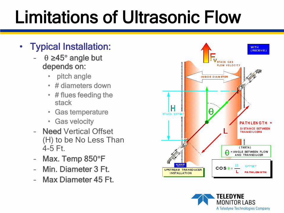
• Typical Installation:– θ ≥45° angle but
depends on:• pitch angle• # diameters down• # flues feeding the
stack• Gas temperature• Gas velocity
– Need Vertical Offset (H) to be No Less Than 4-5 Ft.
– Max. Temp 850°F– Min. Diameter 3 Ft.– Max Diameter 45 Ft.


Typical Transducer Installation
Y = 3” on Stacks <10’ dia.
Y = 6” on Stacks >10’ dia.
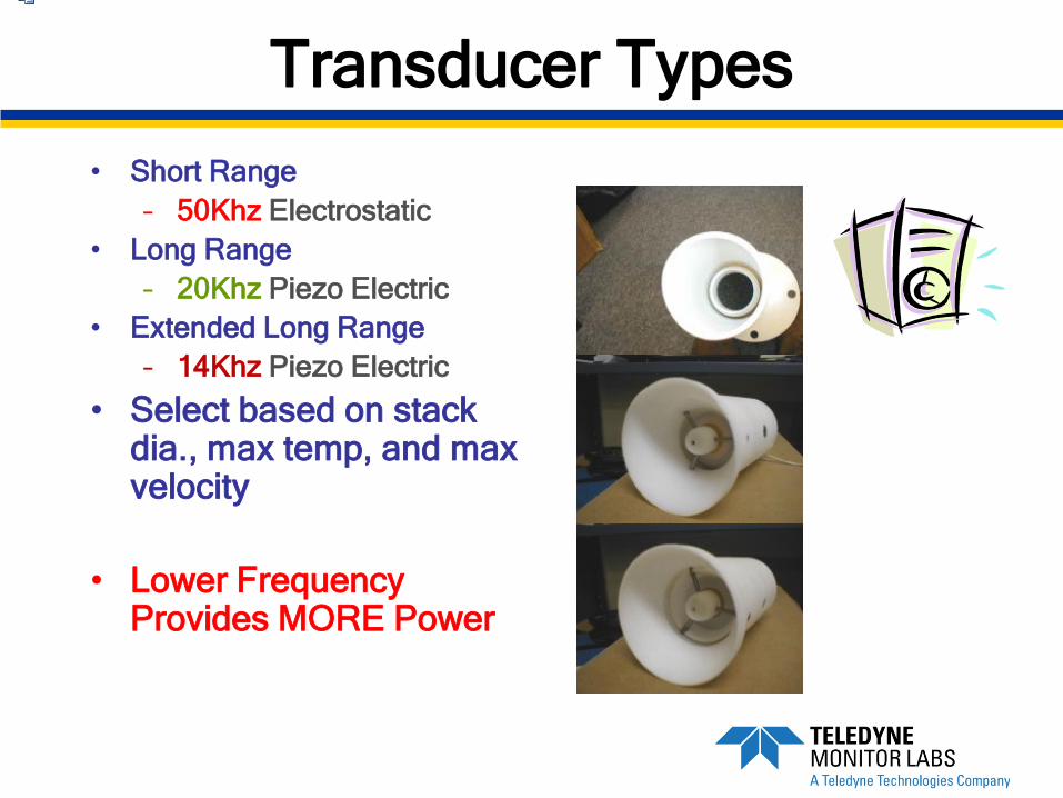
Transducer Types• Short Range
– 50Khz Electrostatic• Long Range
– 20Khz Piezo Electric• Extended Long Range
– 14Khz Piezo Electric
• Select based on stack dia., max temp, and max velocity
• Lower Frequency Provides MORE Power
Ultrasonic Flow Monitor
Believable Concerns
Inherent accuracy of time-of-flight technology
Wall effects, Pitch, Swirl, Multiple Units feeding a common stack
RELATIVE Accuracy……….

Overview
• How Does the Ultrasonic flow monitor Work to Calculate Velocity ?– Tone bursts (Sound) are transmitted from the
upstream transducer to the downstream transducer and then visa versa
– Tone bursts are transmitted approximately every 30 milliseconds in this alternating fashion (33/sec)
– The number of tone bursts sent in each direction is programmable (response time <5.0 seconds)
– The large # of tone bursts enhances accuracy, i.e., a larger statistical sample
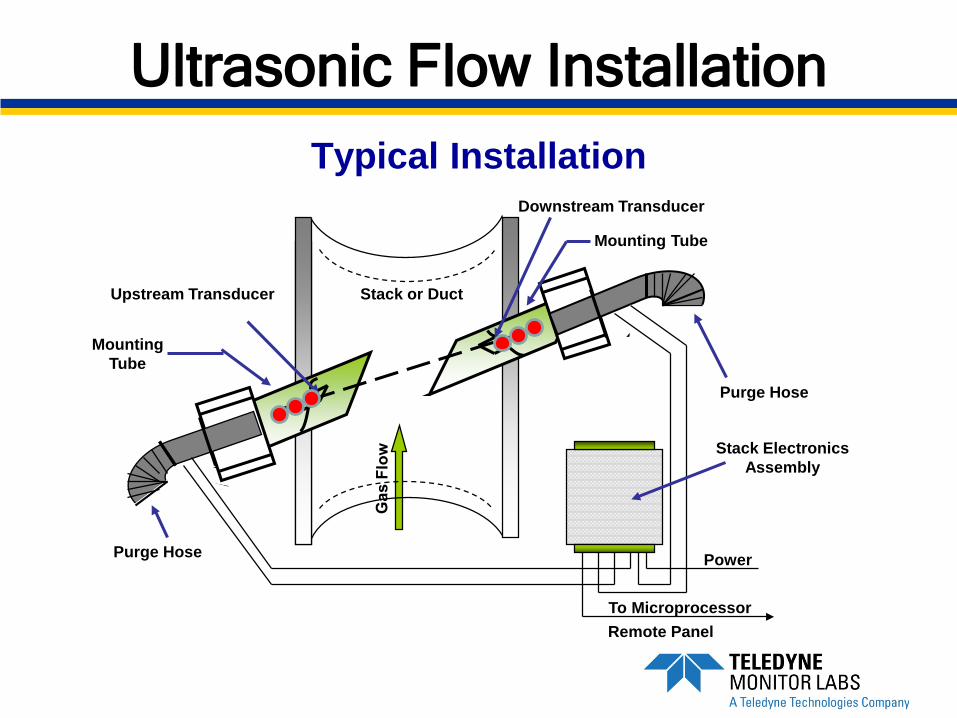
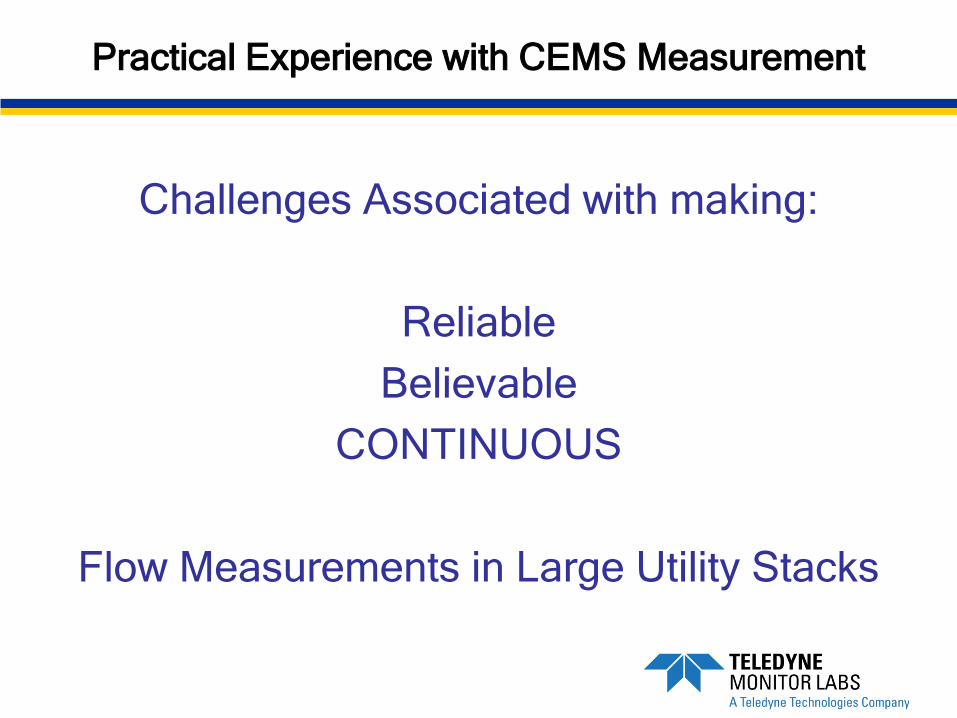
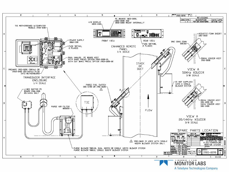
Ultrasonic Flow InstallationTypical Installation
Stack or Duct
Power
Purge Hose
Stack Electronics Assembly
Purge Hose
Mounting Tube
Upstream Transducer
To MicroprocessorRemote Panel
Downstream Transducer
Mounting Tube
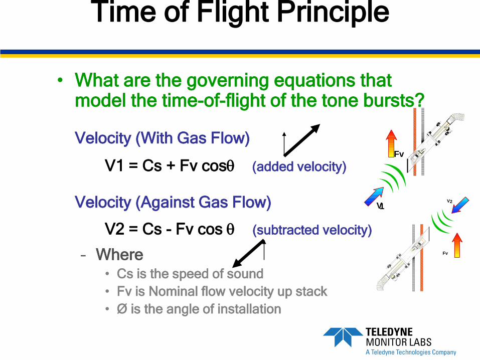
Time of Flight Principle
• What are the governing equations that model the time-of-flight of the tone bursts?
Velocity (With Gas Flow)
V1 = Cs + Fv cosθ (added velocity)
Velocity (Against Gas Flow)
V2 = Cs - Fv cos θ (subtracted velocity)
– Where • Cs is the speed of sound• Fv is Nominal flow velocity up stack• Ø is the angle of installation
V1
Fv
Fv
V2

Velocity (Fv) Calculations
• Cs falls out of the subtracted equations
• Substitute Pathlength/Time for V1 & V2
• Rearrange
)(cos221
θtLtLFv −
=
−
=21
12
)(cos2 ttttLFv
θ
Believable Concerns
Statistical average over time (adjustable response time) leads to accurate flow measurement. Typically 1-5 minutes
Multiple transducers used for mitigation of flow anomalies in stacks (X-Pattern Config.)
Continuous Concerns
Non-Intrusive nature leads to long mean time before failure.
Mitigate the effects of condensing moisture in wet scrubbed stacks. “Weep Holes”
Blower Maintenance to maintain system performance

Field Experience with Ultrasonic
Port Alignment within 1-2 degrees
Consider a “Link-Rod” assembly for large annulus spaces.
Error on the side of a “larger than needed” flow port. Inserts are available!
Field Experience with Ultrasonic
Temperature and pressure will be needed for SCFM calculation. From the monitor or from external devices/inputs.
Safe and accessible mounting locations with “decent” air available for blower intakes.
Questions?
Thank you!
Don GielTeledyne Monitor Labs, Inc.