Embed Size (px)
Citation preview
CLADDING PROPERTIES AFTERHIGH TEMPERATURE OXIDATION
(Session 3)
Chairperson
G. HACHE France

MECHANICAL BEHAVIOUR AT ROOM TEMPERATURE ANDMETALLURGICAL STUDY OF LOW-TIN ZY-4 AND M5TM (ZR-NbO) ALLOYS AFTER OXIDATION AT 1100°C AND QUENCHING
J.C. BRACHET, J. PELCHAT, D. HAMON, R. MAURY CEA-Saclay, Nuclear Energy Division, Gif-sur-Yvette, France
P. JACQUES EDF-SEPTEN, Villeurbanne, France
J.-P. MARDON FRAMATOME-ANP, Nuclear Fuel, Lyon, France
Abstract. During a typical LOCA transient, the fuel cladding tubes are subjected to high temperature oxidation and finally quenched because of the reflooding of the core. The global oxygen content and its distribution affect strongly the residual ductility/toughness of the cladding, which microstructure can be described in terms of zirconia phase, an oxygen enriched phase (* ) and an “ex- ” (*) phase. The main objective of this communication is to summarize some recent results concerning the mechanical behaviour at Room Temperature (R.T.) of Framatome low-tin Zy-4 and M5TM (Zr-NbO) alloys, after single face oxidation at 1 100°C in steam and quenching. The residual ductility/toughness properties at R.T. have been determined using impact, bending and compression tests. A metallurgical study has been made to support these mechanical results. It is observed that, after oxidations giving weight gains ranging from ~4 mg/cm² (~100s) up to ~23 mg/cm² (~3 600s) and according to the measured residual ductility/toughness properties at R.T., the M5TM and Zy-4 alloys show comparable properties. Also, it is worth noticing that, even for the Zr-1%Nb (M5TM) alloy, no hydrogen pick-up is observed after oxidation at 1 100°C. All these results are different from some previous data [1]. Besides, it was found that there is a residual ductility/toughness for both alloys even at the maximum oxidation. To get a better insight of the microstructural origins of the mechanical behaviors observed, microprobe analysis and metallographic studies have been also performed. In particular, it is shown that systematic diffusion of “ß-stabilizing” alloying elements (Fe, Cr, Nb) has occurred ahead of the oxygen stabilized -phase front, within the residual ß-phase. Finally, complementary fractographic observations have been conducted on failed Charpy impact samples.
1. INTRODUCTION
A quite large amount of data has been obtained in the past on Zircaloy type (Zy-2 and Zy-4) cladding behaviour during simulating Loss-Of-Coolant-Accident (LOCA) transients. More recently, new corrosion resistant fuel cladding alloys have been developed to achieve higher burnup. In particular, the M5TM (Zr-1%Nb-O) alloy developed by Framatome-ANP appears to be an attractive alloy and thus, an important R&D program has been conducted at CEA laboratories within the framework of a cooperation between CEA, Famatome-ANP and EDF, to assess its properties in both normal and accidental (RIA, LOCA) conditions [2-4]. In particular, for LOCA conditions, the “EDGAR” methodology has been extensively applied on these new alloys. This methodology has allowed to derive a full modelling of the metallurgical (that is, ß phase transformation temperatures and kinetics) and thermal-mechanical (that is, creep properties, prediction of time/temperature and elongation to rupture…) behaviour upon fast heating/cooling typical of the first stage of LOCA transient
The phase is stabilised at 1 100oC by the diffusion of oxygen under the zirconia layer and, consequently, this phase is very brittle. The “ex- ß is located at the inner part of the cladding and is believed to ensure the residual toughness of the heavily oxidized cladding tube.
139

[3]. To take into account the influence of high-burnup conditions, these studies have been recently extended to pre-hydrided samples and, preliminary tensile tests have been performed on irradiated cladding tubes upon fast heating [4].
The above studies deal with the first stage of the LOCA transient. The purpose of the present paper is to describe the behaviour of Framatome-ANP low-tin Zy-4 and M5TM (Zr-NbO) alloys, after single face oxidation at 1 100°C in steam and quenching, typical of the second stage of the LOCA transient - which is briefly described here-after:
At the end of the LOCA transient, the fuel cladding tubes are subjected to high temperature oxidation (from the LOCA embrittlement criteria point of view, the oxidation temperatures range up to ~1 200°C) and finally quenched because of the reflooding of the core. The resultant microstructure of the clad is known to be a key factor to prevent important failures during or after the quench and to preserve the fuel assembly geometry until the heat generation decays to a sufficiently low level. In particular, the global oxygen content and its spatial distribution within the thickness of the clad affect strongly the residual ductility/toughness of the cladding. The resultant microstructure can be described in terms of three layers:
(1) Zirconia phase - ZrO2 - outer oxide layer. (2) Intermediate oxygen stabilized phase layer – Zr (O) - Due to the high solubility
and to the strong hardening effect of oxygen within the alpha phase, this phase is very brittle.
(3) Inner “ex-ß” phase layer - which is generally considered to be mainly responsible of the residual ductility/toughness of the cladding tube.
So, the main objective of this communication is to summarize some recent results concerning the mechanical behaviour at Room Temperature (R.T.) of Framatome low-tin Zy-4 and M5TM
(Zr-NbO) alloys, after single face oxidation at 1 100°C in steam and quenching. The residual ductility/toughness properties at R.T. have been determined using impact, bending and compression tests. A metallurgical study has been made to support these mechanical results.
2. MATERIALS
All experimental samples were taken from as-received industrial cladding tubes. The materials tested in the present paper are:
- the SRA Zircaloy-4 of the current standard AFA-2G FRAMATOME-ANP fuel assembly, with a low tin content (1.3%) and an optimized fabrication process [5]
- the recrystallized ternary ZrNbO alloy M5TM
processed at low temperature [2, 6]
The chemical compositions of the two alloys are presented in Table 1.
TABLE I. NOMINAL CHEMICAL COMPOSITION OF THE TWO ALLOYS STUDIED
(weight %) Sn Fe Cr Nb O Low-tin Zy-4 (AFA2G) 1.3 0.21 0.1 / 0.125
M5TM / / / 1.0 0.125
140

3. OXIDATION AT 1 100°C AND QUENCHING
Single Face (S.F.) oxidation in steam at 1100°C and quenching have been conducted in the “Dezirox” device shown in Figure 1. The length of the sample is 150 mm and the temperature gradient along the tube is less than 20°C. The quenching is performed by a drop of the sample into water. A “white tissue” is placed in the cooling bath to be able to recover the eventual spalled oxide fragments. Thus, by weighing of both the dropped sample and the spalled zirconia, it is possible to measure the fraction of delamination for each tested samples.
Set Pin
Support Ring
Safety Valve
Steam Boiler
Furnaces
Internal Alumina Tube
SAMPLE
External Alumina Tube
Cooling Annular Device
White Tissue
Cooling Bath Slag Wool
High Temperature Oxidation+ quenching Device
(1700°C – max.
FIG. 1 “Dezirox” device used for the oxidation and quenching experiments.
141
0 500 1000 1500 2000 2500 3000 3500 40000
5
10
15
20
25
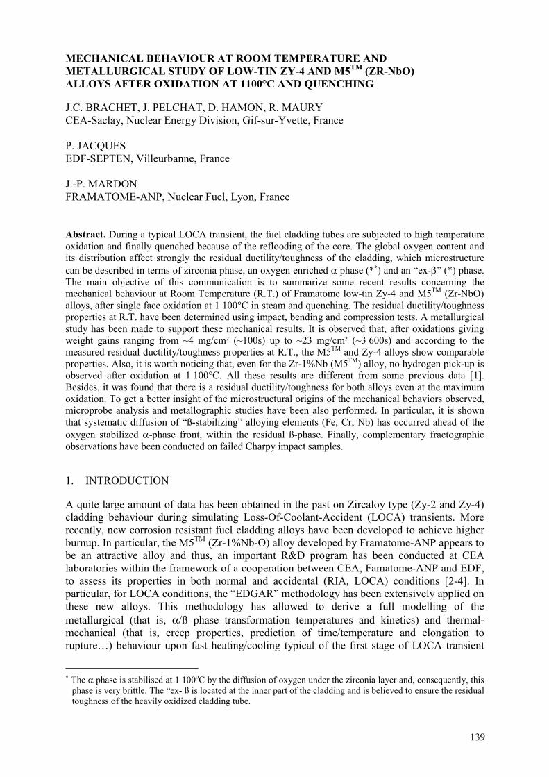
FIG. 2 Evolution of the weight gain as a function of the oxidation time at 1 100°C.
It must be mentioned that no failure of the tested cladding tubes has been observed during the quench, even for the higher oxidation time (~17%ECR).
S.F. oxidation at 1100°C has been conducted for typical weight gains ranging from ~4 mg/cm² (~100s) up to ~23 mg/cm² (~3 600s) – the higher oxidation time has been chosen to be close to ~17% ECR - where the ECR is calculated thanks to the use of “Oxida” model with “Lestikow” laws. The evolution of the measured weight gain as a function of the oxidation time is plotted in Figure 2. It can be observed that the two alloys behave very similarly.
In some cases – that is, for the higher oxidation times – some delamination is observed. Table 2 gives the values of the fraction of spalled zirconia corresponding to three different oxidation tests performed on each alloy at the higher oxidation time (3 100 – 3 800s., i.e., ~17%ECR).
TABLE II. FRACTION OF SPALLED OXIDE AFTER OXIDATION AT 1 100°C
Alloy – n° of Test Oxidation time (s) Oxide spalled (g) Oxide spalled (%) Zy-4 - Test n° 71 3 100 0.7215 66.9 Zy-4 - Test n° 74 3 100 0.6975 64.6 Zy-4 - Test n° 77 3 100 0.9088 83.2 M5TM - Test n°73 3 800 0.0230 2.0 M5TM - Test n°76 3 800 0.0259 2.2 M5TM - Test n°79 3 800 0.0458 3.9
It is obvious from this table that, for these oxidation conditions, delamination is noticeable for the Zy-4 alloy and is negligible for the M5TM one.
Finally, hydrogen chemical analysis has been performed on different samples oxidised up to ~17%ECR. No hydrogen pick-up has been observed for any sample/alloy considered. This last observation seems to be different from the early results of J. Böhmert et al. indicating a
142

noticeable hydrogen pick-up of a Zr-1%Nb type alloy during double face oxidation for 10-30 min. in the 900-1 100°C temperature ranges [1]. For the present M5TM alloy, the obtained oxide layer is black and very adherent up to ~17%ECR.
4. RING COMPRESSION TESTS AT ROOM TEMPERATURE (R.T.)
Figure 3 shows two views of the ring compression test device. The length of each tested sample is 10 mm. The maximum displacement is 6 mm.
On Figure 4, we have plotted typical engineering (Load v.s. Displacement) curves obtained. One can observe different peaks on those curves corresponding, maybe, to the successive failures of different layers of the oxided cladding tubes - that is, ZrO2, Zr (O), Zr(ex-ß).
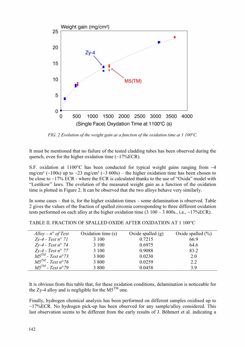
From these engineering curves we have defined a “maximum displacement up to brittle behavior” as shown for the M5TM alloy on Figure 4-b. This typical ductility parameter is plotted as a function of the weight gain in Figure 5.
FIG. 3-a: Starting position FIG. 3-b: max. displacement (6 mm.) FIG. 3 Views of the ring compression test device.
FIG. 4-a: Zy-4 FIG. 4-b: M5TM
FIG. 4 Typical engineering curves obtained from the ring compression tests at R.T.
Zy-43,7mg/cm²
7,8mg/cm²
13,3mg/cm²
21,4mg/cm²
0
500
1000
1500
2000
2500
0 1 2 3 4 5 6
Displacement (mm)
Load
(N)
M5TM
3,6mg/cm²
8,1mg/cm²13,6mg/cm²
22,9mg/cm²0
500
1000
1500
2000
2500
0 1 2 3 4 5 6
Displacement (mm)
Load
(N)
“max. displacement up to brittle behavior”
143
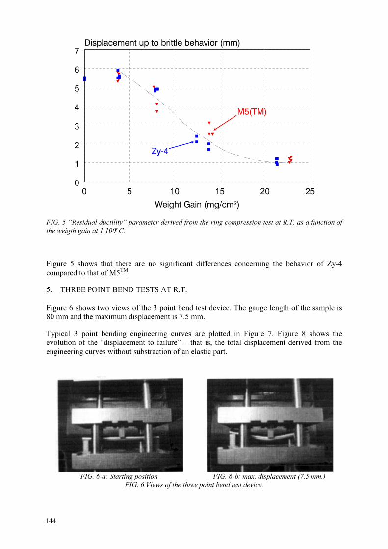
FIG. 5 “Residual ductility” parameter derived from the ring compression test at R.T. as a function of the weigth gain at 1 100°C.
Figure 5 shows that there are no significant differences concerning the behavior of Zy-4 compared to that of M5TM.
5. THREE POINT BEND TESTS AT R.T.
Figure 6 shows two views of the 3 point bend test device. The gauge length of the sample is 80 mm and the maximum displacement is 7.5 mm.
Typical 3 point bending engineering curves are plotted in Figure 7. Figure 8 shows the evolution of the “displacement to failure” – that is, the total displacement derived from the engineering curves without substraction of an elastic part.
FIG. 6-a: Starting position FIG. 6-b: max. displacement (7.5 mm.) FIG. 6 Views of the three point bend test device.
0 5 10 15 20 250
1
2
3
4
5
6
7
144

FIG. 7-a: Zy-4 FIG. 7-b: M5TM
FIG. 7 Typical engineering curves obtained from the 3 point bending tests at R.T.
FIG. 8 Evolution of the “displacement to failure” derived from the 3 point bend test engineering curves as a function of the weight gain at 1 100°C.
145

As for ring compression tests, no significant difference is observed when comparing the residual ductility of the both alloys.
6. IMPACT TESTS AT R.T.
Figure 9 shows a view of the impact pre-notched sample with its typical size values.
Figure 10 shows the evolution of the measured absorbed impact energy of the two alloys as a function of the weight gain. It can be observed that the impact energy values of M5TM are generally slightly higher that those of the low-tin Zy-4 alloy, for a given weight gain value.
From the three types of post-quench mechanical tests at R.T. described above one may conclude that, for the present steam oxidation conditions (1 100°C, single face oxidation), M5TM alloy behaves slightly better than or similar to the low-tin Zy-4 alloy.
55 mm. length
(Pre-notch: radius=1mm, depth = 8mm.)
FIG. 9 Impact pre-notched sample.
FIG. 10 Evolution of the measured absorbed impact energy of the two alloys as a function of the weight gain at 1 100°C.
0 5 10 15 20 250
0.2
0.4
0.6
0.8
M5(TM)
Zy-4
146
7. METALLURGICAL STUDY
To get a better insight of the metallurgical origins of the post-quench mechanical behavior observed on the two alloys, some microstructural observations have been conducted, including fractographs analysis performed on samples failed by impact tests at R.T.
7.1 Overall microstructural observations
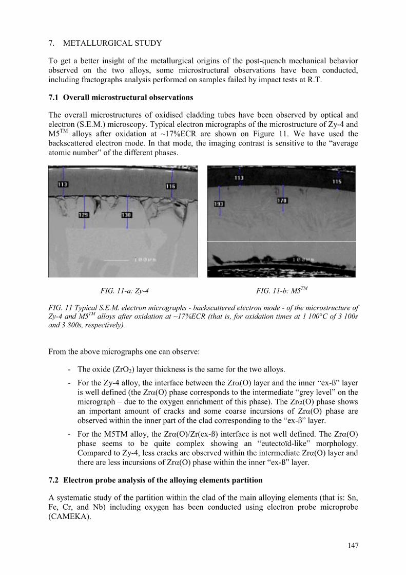
The overall microstructures of oxidised cladding tubes have been observed by optical and electron (S.E.M.) microscopy. Typical electron micrographs of the microstructure of Zy-4 and M5TM alloys after oxidation at ~17%ECR are shown on Figure 11. We have used the backscattered electron mode. In that mode, the imaging contrast is sensitive to the “average atomic number” of the different phases.
FIG. 11-a: Zy-4 FIG. 11-b: M5TM
FIG. 11 Typical S.E.M. electron micrographs - backscattered electron mode - of the microstructure of Zy-4 and M5TM alloys after oxidation at ~17%ECR (that is, for oxidation times at 1 100°C of 3 100s and 3 800s, respectively).
From the above micrographs one can observe:
- The oxide (ZrO2) layer thickness is the same for the two alloys.
- For the Zy-4 alloy, the interface between the Zr (O) layer and the inner “ex-ß” layer is well defined (the Zr (O) phase corresponds to the intermediate “grey level” on the micrograph – due to the oxygen enrichment of this phase). The Zr (O) phase shows an important amount of cracks and some coarse incursions of Zr (O) phase are observed within the inner part of the clad corresponding to the “ex-ß” layer.
- For the M5TM alloy, the Zr (O)/Zr(ex-ß) interface is not well defined. The Zr (O) phase seems to be quite complex showing an “eutectoïd-like” morphology. Compared to Zy-4, less cracks are observed within the intermediate Zr (O) layer and there are less incursions of Zr (O) phase within the inner “ex-ß” layer.
7.2 Electron probe analysis of the alloying elements partition
A systematic study of the partition within the clad of the main alloying elements (that is: Sn, Fe, Cr, and Nb) including oxygen has been conducted using electron probe microprobe (CAMEKA).
147
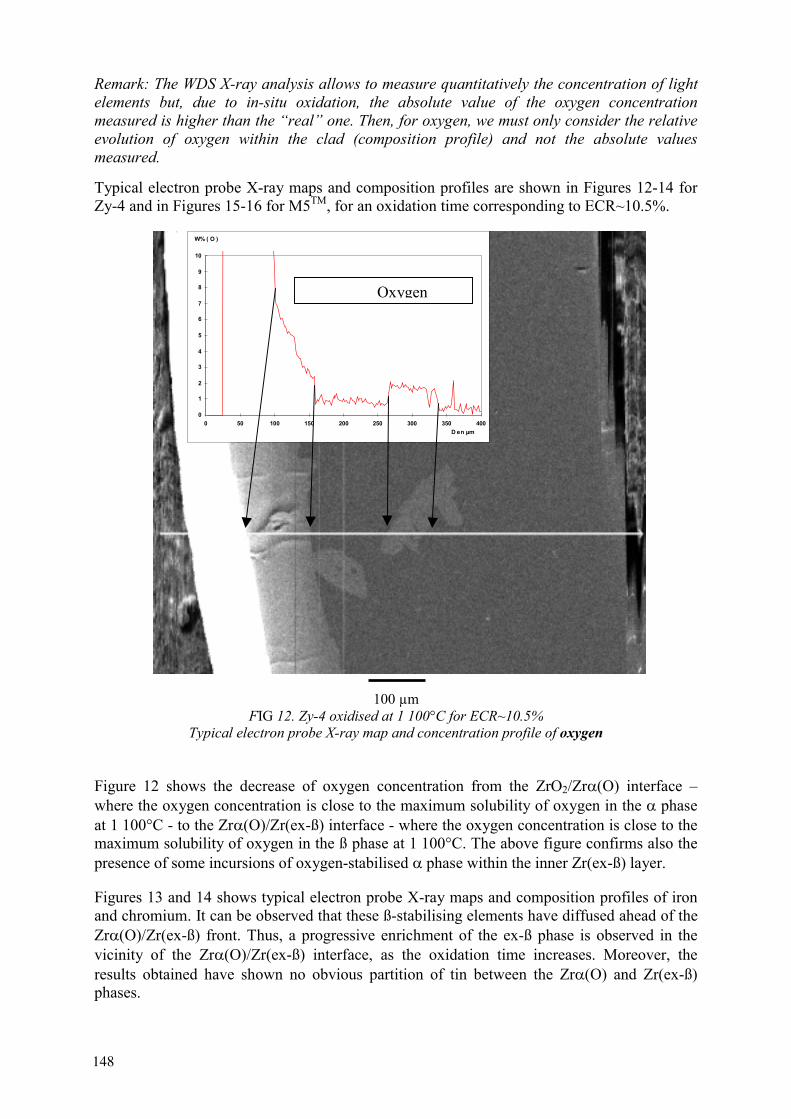
Remark: The WDS X-ray analysis allows to measure quantitatively the concentration of light elements but, due to in-situ oxidation, the absolute value of the oxygen concentration measured is higher than the “real” one. Then, for oxygen, we must only consider the relative evolution of oxygen within the clad (composition profile) and not the absolute values measured.
Typical electron probe X-ray maps and composition profiles are shown in Figures 12-14 for Zy-4 and in Figures 15-16 for M5TM, for an oxidation time corresponding to ECR~10.5%.
100 µm FIG 12. Zy-4 oxidised at 1 100°C for ECR~10.5%
Typical electron probe X-ray map and concentration profile of oxygen
Figure 12 shows the decrease of oxygen concentration from the ZrO2/Zr (O) interface – where the oxygen concentration is close to the maximum solubility of oxygen in the phase at 1 100°C - to the Zr (O)/Zr(ex-ß) interface - where the oxygen concentration is close to the maximum solubility of oxygen in the ß phase at 1 100°C. The above figure confirms also the presence of some incursions of oxygen-stabilised phase within the inner Zr(ex-ß) layer.
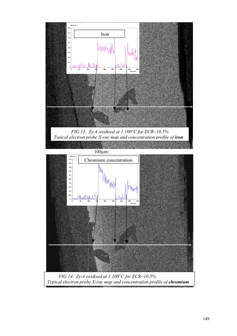
Figures 13 and 14 shows typical electron probe X-ray maps and composition profiles of iron and chromium. It can be observed that these ß-stabilising elements have diffused ahead of the Zr (O)/Zr(ex-ß) front. Thus, a progressive enrichment of the ex-ß phase is observed in the vicinity of the Zr (O)/Zr(ex-ß) interface, as the oxidation time increases. Moreover, the results obtained have shown no obvious partition of tin between the Zr (O) and Zr(ex-ß) phases.
0
1
2
3
4
5
6
7
8
9
10
0 50 100 150 200 250 300 350 400D en µm
W% ( O )
Oxygen
148
100µm:
0
0.1
0.2
0.3
0.4
0.5
0.6
0.7
0.8
0 50 100 150 200 250 300 350 400D en µm
W% ( Fe )
Iron
FIG 13. Zy-4 oxidised at 1 100°C for ECR~10.5% Typical electron probe X-ray map and concentration profile of iron
FIG 14. Zy-4 oxidised at 1 100°C for ECR~10.5% Typical electron probe X-ray map and concentration profile of chromium
0
0.05
0.1
0.15
0.2
0.25
0.3
0.35
0.4
0.45
0.5
0 50 100 150 200 250 300 350 400D en µm
W% ( Cr )
Chromium concentration
149
(1) M5TM oxidised for 1 530 s at 1 100°C (ECR~10.5%)
100µm:
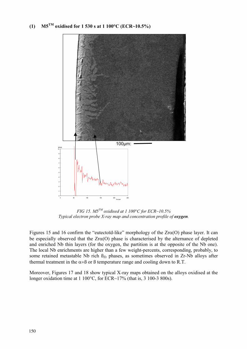
FIG 15. M5TM oxidised at 1 100°C for ECR~10.5% Typical electron probe X-ray map and concentration profile of oxygen.
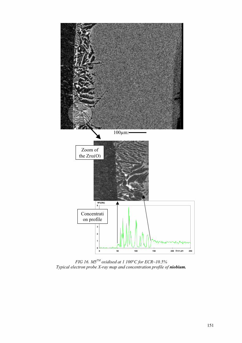
Figures 15 and 16 confirm the “eutectoïd-like” morphology of the Zr (O) phase layer. It can be especially observed that the Zr (O) phase is characterised by the alternance of depleted and enriched Nb thin layers (for the oxygen, the partition is at the opposite of the Nb one). The local Nb enrichments are higher than a few weight-percents, corresponding, probably, to some retained metastable Nb rich ßZr phases, as sometimes observed in Zr-Nb alloys after thermal treatment in the ß or ß temperature range and cooling down to R.T.
Moreover, Figures 17 and 18 show typical X-ray maps obtained on the alloys oxidised at the longer oxidation time at 1 100°C, for ECR~17% (that is, 3 100-3 800s).
0
1
2
3
4
5
6
7
8
9
10
0 50 100 150 200 250D en µm
W%(O)
150
100µm:
FIG 16. M5TM oxidised at 1 100°C for ECR~10.5% Typical electron probe X-ray map and concentration profile of niobium.
Zoom of the Zr (O)
0
1
2
3
4
5
6
0 50 100 150 200 250D en µm
W%(Nb)
Concentration profile
151

(image sizes = 768 x 768 µm)
FIG. 17 Typical X-ray maps obtained on Zy-4 oxidised for 3 100s at 1 100°C (ECR~17%).
O
Fe
Cr
152
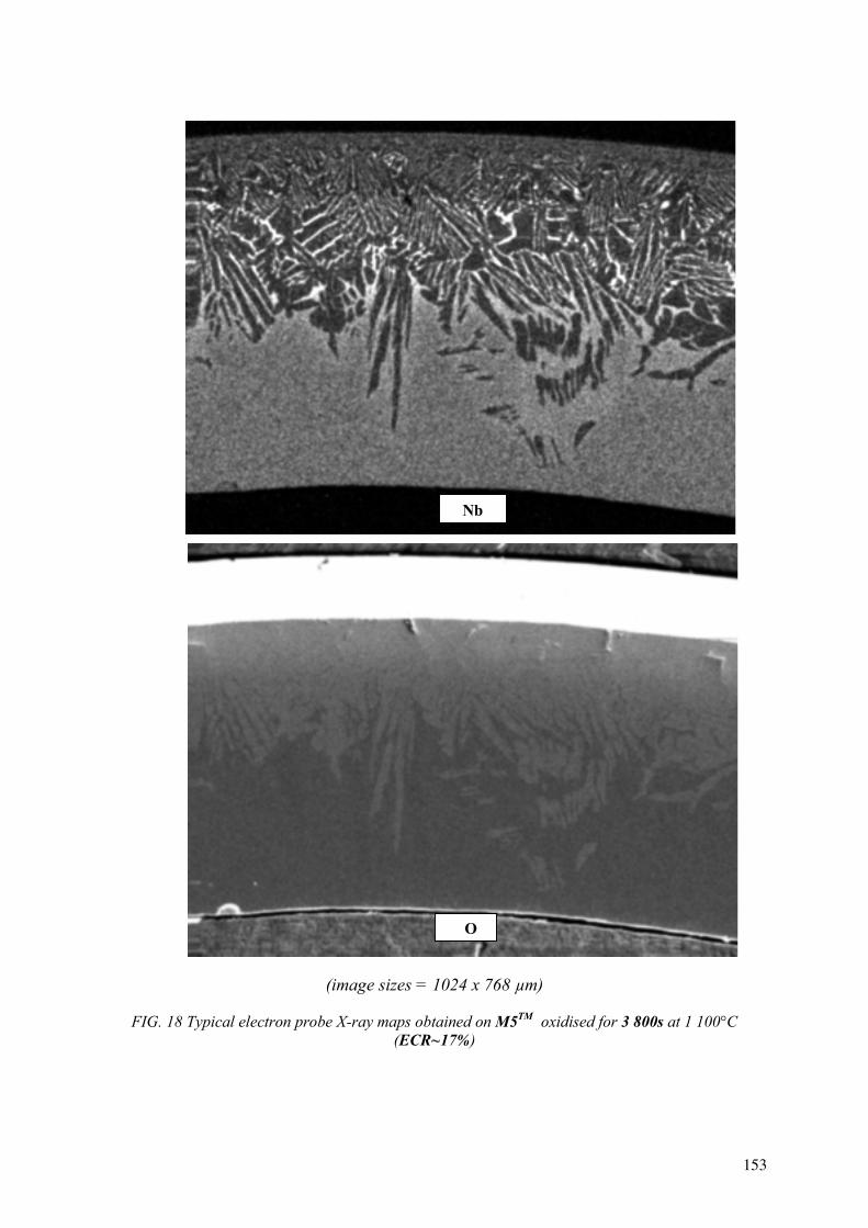
(image sizes = 1024 x 768 µm)
FIG. 18 Typical electron probe X-ray maps obtained on M5TM oxidised for 3 800s at 1 100°C (ECR~17%)
O
Nb
153
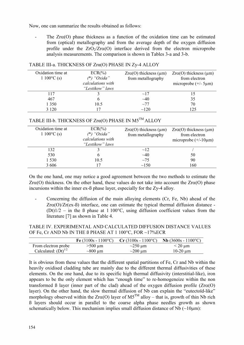
Now, one can summarize the results obtained as follows:
- The Zr (O) phase thickness as a function of the oxidation time can be estimated from (optical) metallography and from the average depth of the oxygen diffusion profile under the ZrO2/Zr (O) interface derived from the electron microprobe analysis measurements. The comparison is shown in Tables 3-a and 3-b.
TABLE III-a. THICKNESS OF Zr (O) PHASE IN Zy-4 ALLOY Oxidation time at
1 100°C (s) ECR(%)
(*) “Oxida” calculations with “Lestikow” laws
Zr (O) thickness (µm) from metallography
Zr (O) thickness (µm) from electron
microprobe (+/- 5µm)
117 3 ~17 15 467 6 ~40 35
1 350 10.5 ~77 70 3 120 17 ~120 125
TABLE III-b. THICKNESS OF Zr (O) PHASE IN M5TM ALLOY Oxidation time at
1 100°C (s) ECR(%)
(*) “Oxida” calculations with “Lestikow” laws
Zr (O) thickness (µm) from metallography
Zr (O) thickness (µm) from electron
microprobe (+/-10µm)
132 3 ~12 / 530 6 ~40 50
1 530 10.5 ~75 90 3 606 17 ~150 160
On the one hand, one may notice a good agreement between the two methods to estimate the Zr (O) thickness. On the other hand, these values do not take into account the Zr (O) phase incursions within the inner ex-ß phase layer, especially for the Zy-4 alloy.
- Concerning the diffusion of the main alloying elements (Cr, Fe, Nb) ahead of the Zr (O)/Zr(ex-ß) interface, one can estimate the typical thermal diffusion distance - (Dt)1/2 – in the ß phase at 1 100°C, using diffusion coefficient values from the literature [7] as shown in Table 4.
TABLE IV. EXPERIMENTAL AND CALCULATED DIFFUSION DISTANCE VALUES OF Fe, Cr AND Nb IN THE ß PHASE AT 1 100°C, FOR ~17%ECR
Fe (3100s - 1100°C) Cr (3100s - 1100°C) Nb (3600s - 1100°C) From electron probe >500 µm ~250 µm < 20 µm Calculated: (Dt)1/2 ~800 µm ~200 µm 10-20 µm
It is obvious from these values that the different spatial partitions of Fe, Cr and Nb within the heavily oxidised cladding tube are mainly due to the different thermal diffusivities of these elements. On the one hand, due to its specific high thermal diffusivity (interstitial-like), iron appears to be the only element which has “enough time” to re-homogeneize within the non transformed ß layer (inner part of the clad) ahead of the oxygen diffusion profile (Zr (O) layer). On the other hand, the slow thermal diffusion of Nb can explain the “eutectoïd-like” morphology observed within the Zr (O) layer of M5TM alloy – that is, growth of thin Nb rich ß layers should occur in parallel to the coarse alpha phase needles growth as shown schematically below. This mechanism implies small diffusion distance of Nb (~10µm):
154
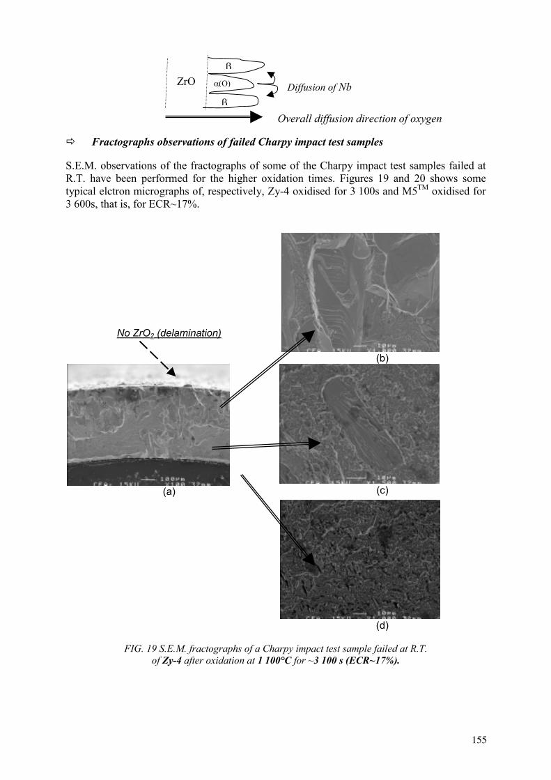
Fractographs observations of failed Charpy impact test samples
S.E.M. observations of the fractographs of some of the Charpy impact test samples failed at R.T. have been performed for the higher oxidation times. Figures 19 and 20 shows some typical elctron micrographs of, respectively, Zy-4 oxidised for 3 100s and M5TM oxidised for 3 600s, that is, for ECR~17%.
No ZrO2 (delamination)
(b)
(a) (c)
(d)
FIG. 19 S.E.M. fractographs of a Charpy impact test sample failed at R.T. of Zy-4 after oxidation at 1 100°C for ~3 100 s (ECR~17%).
ZrO (O) Diffusion of Nb
Overall diffusion direction of oxygen
155
ZrO2 (no delamination)
(b)
(a) (c)
(e) (d)
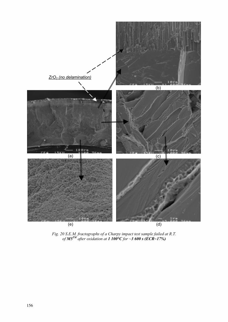
Fig. 20 S.E.M. fractographs of a Charpy impact test sample failed at R.T. of M5TM after oxidation at 1 100°C for ~3 600 s (ECR~17%)
156

From Figures 19 and 20 it can be observed:
- the confirmation of important delamination of the ZrO2 layer for Zy-4 (not for M5TM);
- the columnar brittle failure mode of the ZrO2 layer (see Fig. 20-b);
- the cleavage and/or intergranular full brittle failure mode of the intermediate Zr (O) layer (Figs. 19-b and 20-b) – with some indication of localised ductile failure mode of the Nb enriched (ß?) stringers of the M5TM alloy (Figs. 20-c and 20-d);
- the full ductile failure mode of the inner ex- ß layer of the two alloys, but with indications of a lower residual ductility for the Zy-4 (incursions of coarse Zr (O) – Fig. 19-c - and more flat dimples – Fig. 19-d) than for the M5TM (more spherical dimples – Fig. 20-e). This last trend has been also confirmed for lower ECR values (~10.5%).
To try to explain the slightly lower toughness observed on Zy-4 compared to M5TM for ECR ranging from ~10% to ~17%, we have performed electron microprobe analysis of oxygen and micro-hardness measurements on the inner part of the clad corresponding to the “ex-ß” phase. The results obtained are presented in Table 5.
TABLE V. OXYGEN CONTENT AND HARDNESS OF THE INNER (EX-ß PHASE) LAYER OF THE CLAD AFTER OXIDATION AT 1 100°C UP TO ~17%ECR AND QUENCHING
Weight-ppm of oxygen (*) Vickers hardness (50g) Zy-4 oxidised for ~3 100s at 1 100°C 5 500-6 000 330-370 M5TM oxidised for ~3 600s at 1 100°C 2 000-4 000 260-300
From the above oxygen concentration and hardness values one can make the assumption that, for the present oxidation conditions (steam, 1100°C, single face), the inner ex- ß phase layer of Zy-4 contains more oxygen and, consequently, the post-quench residual toughness at R.T. is lower than that of the M5TM alloy due to the hardening/embrittlement effect of interstitial oxygen in solid solution.
8. MAIN CONCLUSIONS
It has been observed that, after single face oxidations at 1 100°C in steam giving weight gains ranging from ~4 mg/cm² (~100s) up to ~23 mg/cm² (~3 600s):
- according to the measured residual ring compression test and three point bending test properties at R.T., the M5TM and Zy-4 alloys show comparable post-quench mechanical behavior. Compared to M5TM, only a slightly lower toughness of Zy-4 is observed for the Charpy impact test performed at R.T., which can be attributed to a higher oxygen content within the inner (ex-ß) layer of
* As mentioned earlier, the absolute values of oxygen are difficult to determine due to “in-situ” oxidation; however, the relative difference between the oxygen contents of the two alloys is considered to be accuratly measured.
157

the clad. Besides, it was found that there is a residual ductility/toughness for both alloys even at the maximum oxidation.
- for the higher oxidation time, that is 3 100-3 600s, delamination of at least 60% is observed for Zy-4 but is still negligible for the M5TM alloy
- it is worth noticing that, even for the Zr-1%Nb (M5TM) alloy, no hydrogen pick-up is observed after oxidation at 1 100°C up to 3 600s,
- the metallurgical studies performed have shown that the different spatial partitions of alloying elements ahead of the Zr (O)/Zr(ex-ß) interface are due to the very different thermal diffusivities of these elements within the ß-phase.
REFERENCES
[1] BÖHMERT, J., DIETRICH, M., LINEK, J., “Comparative studies on high-temperature corrosion of ZrNb1 and Zircaloy-4“, Nuclear Engineering and Design 147 (1993), 53-62.
[2] MARDON, J. P., CHARQUET, D., SENEVAT, J., “Influence of Composition and Fabrication Process on Out-of-Pile and In-Pile Properties of M5 Alloy,” Zirconium in the Nuclear Industry: Twelfth International Symposium, ASTM STP 1354, G. P. Sabol and G. D. Moan, Eds., American Society for Testing and Materials, West Conshohocken, PA, (2000), pp. 505-524.
[3] FORGERON, T., BRACHET, J.-C., BARCELO F., CASTAING, A., HIVROZ, J., MARDON, J.-P., BERNAUDAT, C., « Experiment and modeling of advanced fuel rod cladding behavior under LOCA conditions: ß phase transformation kinetics and EDGAR methodology », Zirconium in the Nuclear Industry: Twelfth International Symposium, ASTM STP 1354, G. P. Sabol and G. D. Moan, Eds., American Society for Testing and Materials, West Conshohocken, PA, (2000), pp. 256-278.
[4] BRACHET, J-C, PORTIER, L., FORGERON, T., HIVROZ, J., HAMON, D., GUILBERT, T., BREDEL, T., YVON, P., MARDON, J-P., and JACQUES, P., , “Influence of hydrogen content on the ß phase transformation temperatures and on the thermal-mechanical behavior of Zy-4, M4 (ZrSnFeV) and M5
TM (ZrNbO) alloys during
the first phase of LOCA transient,” Zirconium in the Nuclear Industry: 13th. International Symposium, June 10-14 2001, Annecy, France, to be published in ASTM STP (2002)
[5] MARDON, J.P., CHARQUET, D., SENEVAT, J., "Optimization of PWR behavior of stress-relieved Zircaloy-4 cladding tubes by upgrading the manufacturing and inspection process", ASTM STP 1245, pp 329-348.
[6] MARDON, J. P., GARNER, G., BESLU, P., CHARQUET, D., SENEVAT, J., "Update on the development of advanced Zr alloys for PWR fuel rod claddings", ANS Portland, 2-6/03/1997, pp. 405-412.
[7] LANDOLT-BÖRNSTEIN, “Diffusion in Solid Metals and Alloys”, New Series / Group III / Vol. 26, pp. 109-110.
158
EFFECT OF HYDROGEN CONTENT ON THE EMBRITTLEMENT OF ZR ALLOYS
Z. HÓZER, Á. GRIGER, L. MATUS, L. VASÁROS, M. HORVÁTH KFKI Atomic Energy Research Institute, Budapest, Hungary
Abstract. An experimental series has been carried out in the KFKI Atomic Energy Research Institute in order to clear up the role of oxidation and H uptake in the Zr cladding embrittlement process. Russian E110 type Zr1%Nb and Zircaloy-4 cladding were used and the differences between the two alloys were also examined. The sample preparation covered the following cases:
Oxidation in steam, Oxidation in Ar+O2 atmosphere, Hydrogenisation of as received and oxidised in Ar+O2 atmosphere samples.
The oxidation in Ar+O2 and later hydrogenisation possible to produce samples with well characterised H and O content. The hydrogen content of samples oxidised in steam was determined after mechanical testing using high temperature desorption. The results of the experiments provided detailed information on the effect of H and O content of the embrittlement of Zr alloys. The most important conclusions were the followings:
Hydrogen seems to play a more important role in embrittlement of Zr alloys than oxygen. The Zry-4 samples becomes brittle at lower H content than the Zr1%Nb. Under steam oxidation conditions the Zr1%Nb alloy takes up much more H than the Zry-4 and it resulted in earlier embrittlement. This explains the observed difference in ring compression tests with E110 (Zr1%Nb) and Zry-4 claddings.
1. INTRODUCTION
During a LOCA accident at high temperature the oxidation process of zirconium alloy claddings in steam creates an external oxide layer on the tube surface and produces hydrogen. A part of the hydrogen can be absorbed by the metal [1]. The oxide layer, the oxygen and hydrogen content degrades the mechanical properties of the cladding it mostly results in the embrittlement of the alloys. The embrittlement can lead to the failure of the fuel rods under accidental conditions, especially during the reflooding of the hot nuclear core.
The effect of oxidation on the embrittlement as well as the failure of the zirconium cladding is well known and is expressed in the ECR (Equivalent Cladding Reacted) criteria. Earlier the effect of hydrogen content was not considered of high interest for LOCA cases, in spite of the fact, that some preliminary studies indicated its importance. The presence of hydrogen in the metal leads to the formation of the cubic -ZrH2 and the -ZrH compounds [2], which result in texture changes and cause a significant embrittlement of the originally ductile material.
The cladding material of Western type PWRs is Zircaloy alloy, the Russian design VVER reactors apply Zr1%Nb cladding. There are differences between the mechanical properties and corrosion resistance of these alloys: the Zircaloy has higher mechanical properties and the Zr1%Nb has better corrosion resistance during normal operation.
The comparison of the behaviour of Zircaloy and Zr1%Nb cladding in steam oxidation conditions including the changes of their mechanical properties (ring compression test) was first carried out by Böhmert et.al.[3]. Their results indicated some differences between the properties of the two claddings. The embrittlement of Zr1%Nb was observed at lower oxidation ratio. Several years ago similar experiments with Zr1%Nb cladding were performed in the AEKI [1]. The results confirmed the strong embrittlement of Zr1%Nb alloy during steam oxidation.
159
In the present work comparative studies were carried out to investigate the differences at high temperature steam corrosion processes and to determine the effect of the corrosion on the embrittlement of Zr1%Nb and Zircaloy-4 alloys. The separate effect of oxygen and hydrogen content on the embrittlement of the two alloys was also studied.
2. EXPERIMENTAL
In order to clear up the role of oxygen and hydrogen uptake in the embrittlement process mechanical tests (ring compression tests) were carried out with Russian E110 type Zr1%Nb and Zircaloy-4 cladding samples of different corrosion states in the KFKI Atomic Energy Research Institute. The Zr1%Nb (E110) was received from Russia, while the Zircaloy-4 cladding was of German origin. For both type alloys the same experimental procedures and equipment were applied in order to avoid any system effect. The samples were cut from cladding tubes without pellets. The diameter and the thickness of tubes were 9,1/0,65 mm for Zr1%Nb and 10,75/0,625 for Zircaloy-4 and the samples were uniformly 8 mm long. Before the experimental procedures the surfaces were degreased. The initial weight of the samples was measured with 0,01 mg and the size with 0,01 mm accuracy. In all cases two-sided (internal and external surfaces of the cladding) oxidation and/or hydrogenisation took place. The sample preparation covered the following cases:
Oxidation of samples in Ar+O2 atmosphere, Hydrogenisation of as received samples and samples pre-oxidised in Ar+O2atmosphere,Oxidation of samples in steam.
The samples were characterised by their oxygen and hydrogen content. The oxygen content was defined as oxidation ratio, which meant the amount of oxygen taken up by the sample as the fraction of the total oxygen needed to its full oxidation (0% for the initial case and 100% for total oxidation). The oxidation ratio of samples was determined on the basis of weight gain. The hydrogen content (uniformly in mass ppm) of samples oxidised in steam was determined by high temperature desorption method. The hydrogenisation process of the as received and the pre-oxidised samples made the production of samples with well characterised hydrogen content possible. In this case the hydrogen content of samples was considered to be identical with the known quantity of hydrogen absorbed in the reaction.
2.1. Oxidation in argon+oxygen atmosphere
High temperature furnace at 800oC was used for the oxidation of samples in argon+oxygen atmosphere. The argon to oxygen volumetric ratio was 3:1. The samples were put into a quartz tube and the gas was injected with a constant volumetric flowrate of 80 ml/min. Three series of samples were produced with approximately 5 m, 10 m and 20 m thickness of equivalent oxide layer.
2.2. Hydrogenisation
The hydrogenisation of the as received and pre-oxidised zirconium cladding samples was carried out in a special furnace with a vacuum system and calibrated gas manipulation system. The sample was put into the cold part of the reaction chamber outside of the furnace. Then the
160
system was evacuated and flushed with high purity hydrogen several times. The reaction area with the sample was evacuated and the Zr sample was moved for several minutes to the heated part of the quartz tube at 900 oC in order to remove the surface contamination. The required amount of hydrogen was injected to the reaction area from the calibrated volume. Reaching the equilibrium state of hydrogen absorption – indicated by the pressure measurement - the sample was moved back to the cold part of the quartz tube. The absorption of the total dosing hydrogen in the metal was supposed and the amount of absorbed hydrogen was determined from the volumetric data.
2.3. Oxidation in steam
Steam oxidation was performed with steam+argon mixture, which included 12%vol argon gas. The inert gas of small amount does not influence the oxidation kinetics and as a carrier gas for the hydrogen enhanced the accurate hydrogen concentration measurement under the reaction. The inlet gas velocity was 8.5-11 cm/s, which meant unlimited steam supply for the oxidation. The oxidation temperature was varied between 900-1 200oC and at each temperature several samples were oxidised for different times.
Heating up of the furnace to the requested temperature and adjusting a constant gas flow through the system, at equilibrium flow and thermal conditions the sample was moved into the furnace. Elapsing the required time the sample was removed from the furnace. During this oxidation treatment the hydrogen concentration in the outlet gas flow was monitored and recorded. The history curve of hydrogen production showed the intensity of oxidation and its integral helped to estimate the fraction of hydrogen taken up by the zirconium alloys. The more accurate hydrogen content of the samples was determined by high temperature desorption method using the broken pieces of the rings after mechanical testing.
2.4. Mechanical testing
As received and corrosion treated ring samples with 8 mm height were examined in radial compression tests using electromechanical tensile-compressive standard test machine. The velocity of the crosshead moving was 2 mm/min. The force-deformation curves were recorded and the crushing force and deformation were determined. Generally 2-3 cracks were detected but always the first crack was considered as failure. The rings were loaded until the total plastic deformation or at least until the first indication of cracking. The actual value of relative deformation occurred at the first cracking was used for the characterisation of the level of embrittlement (the relative deformation is the ratio of the deformation path and the initial diameter of the tested ring). The effect of ductile/brittle behaviour was expressed in the term of relative deformation.
3. RESULTS AND DISCUSSION
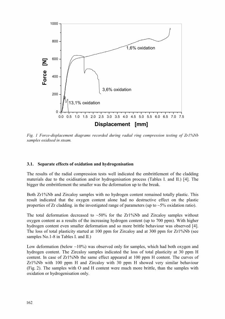
For the samples with different oxidation/hydrogenisation conditions the same ring compression testing procedure was applied to determine the change of ductility and to characterise the embrittlement process of the two type alloys. The as received - non-oxidised/hydrogenised - samples were totally plastic they deformed without cracking and reached 100% relative deformation. The samples containing oxygen and hydrogen in significant amount showed more brittle behaviour. Figure 1. shows typical compression diagrams for Zr1%Nb samples oxidised at 900oC at different extents.
161
0.0 0.5 1.0 1.5 2.0 2.5 3.0 3.5 4.0 4.5 5.0 5.5 6.0 6.5 7.0 7.50
200
400
600
800
1000
13,1% oxidation
1,6% oxidation
3,6% oxidation
Forc
e [
N]
Displacement [mm]
Fig. 1 Force-displacement diagrams recorded during radial ring compression testing of Zr1%Nb samples oxidised in steam.
3.1. Separate effects of oxidation and hydrogenisation
The results of the radial compression tests well indicated the embrittlement of the cladding materials due to the oxidisation and/or hydrogenisation process (Tables I. and II.) [4]. The bigger the embrittlement the smaller was the deformation up to the break.
Both Zr1%Nb and Zircaloy samples with no hydrogen content remained totally plastic. This result indicated that the oxygen content alone had no destructive effect on the plastic properties of Zr cladding. in the investigated range of parameters (up to ~5% oxidation ratio).
The total deformation decreased to ~50% for the Zr1%Nb and Zircaloy samples without oxygen content as a results of the increasing hydrogen content (up to 700 ppm). With higher hydrogen content even smaller deformation and so more brittle behaviour was observed [4]. The loss of total plasticity started at 100 ppm for Zircaloy and at 300 ppm for Zr1%Nb (see samples No.1-8 in Tables I. and II.)
Low deformation (below ~10%) was observed only for samples, which had both oxygen and hydrogen content. The Zircaloy samples indicated the loss of total plasticity at 30 ppm H content. In case of Zr1%Nb the same effect appeared at 100 ppm H content. The curves of Zr1%Nb with 100 ppm H and Zircaloy with 30 ppm H showed very similar behaviour (Fig. 2). The samples with O and H content were much more brittle, than the samples with oxidation or hydrogenisation only.
162

TABLE I. RELATIVE DEFORMATION OF Zr1%Nb CLADDING WITH DIFFERENT HYDROGEN CONTENT AND OXIDATION RATIO
TABLE II. RELATIVE DEFORMATION OF ZIRCALOY-4 CLADDING WITH DIFFERENT HYDROGEN CONTENT AND OF OXIDATION RATIO
No. Sample Oxidation
ratio[%]
Hcontent[ppm]
Relative deformation
[%]No.
Sample Oxidation
ratio[%]
Hcontent[ppm]
Relative deformation
[%]1 NbER1 0 0 100 1 YER1 0 0 100 2 NbER2 0 0 100 2 YER2 0 0 100 3 NbER3 0 30 100 3 YER3 0 30 100 4 NbER4 0 30 100 4 YER4 0 30 100 5 NbER5 0 100 100 5 YER5 0 100 63,3 6 NbER6 0 100 100 6 YER6 0 100 65,1 7 NbER7 0 300 68,7 7 YER7 0 300 59,6 8 NbER8 0 300 69,3 8 YER8 0 300 54,9 9 NbER8 0 700 54,2 9 YER8 0 700 44,6
10 NbER8 0 700 48,6 10 YER8 0 700 51,2 11 NbOX051 1,0 0 100 11 YOX051 1,0 0 100 12 NbOX052 1,1 0 100 12 YOX052 0,8 0 100 13 NbOX053 1,3 30 100 13 YOX053 1,0 30 34,5 14 NbOX054 1,2 100 39,9 14 YOX054 0,8 100 15,8 15 NbOX055 1,3 300 9,9 15 YOX055 1,1 300 8,4 16 NbOX056 1,4 700 6,6 16 YOX056 1,0 700 8,3 17 NbOX101 2,1 0 100 17 YOX101 1,7 0 100 18 NbOX102 2,4 0 100 18 YOX102 1,7 0 100 19 NbOX103 2,3 30 100 19 YOX103 1,3 30 39,0 20 NbOX104 2,3 100 22,0 20 YOX104 1,4 100 14,8 21 NbOX105 2,4 300 12,1 21 YOX105 1,7 300 8,3 22 NbOX106 2,2 700 9,9 22 YOX106 1,7 700 11,1 23 NbOX201 4,3 0 100 23 YOX201 3,7 0 100 24 NbOX202 3,8 0 100 24 YOX202 3,3 0 100 25 NbOX203 4,0 30 40,5 25 YOX203 3,6 30 20,4 26 NbOX204 3,9 100 32,8 26 YOX204 3,0 100 14,8 27 NbOX205 3,4 300 12,0 27 YOX205 3,4 300 9,2 28 NbOX206 4,2 700 9,8 28 YOX206 3,3 700 9,3
0 1 2 3 4 5 6 7 80
10
20
30
40
50
60
70
80
90
100 Zr1%Nb 0 ppm H Zr1%Nb 30 ppm H Zr1%Nb 100 ppm H Zr1%Nb 300 ppm H Zr1%Nb 700 ppm H Zircaloy 0 ppm H Zircaloy 30 ppm H Zircaloy 100 ppm H Zircaloy 300 ppm H Zircaloy 700 ppm H
Rel
ativ
e de
form
atio
n [
%]
Oxidation ratio [%]
Fig. 2 Relative deformation of Zr1%Nb and Zircaloy samples as function of oxidation ratio and hydrogen content.
163

3.2. Effect of oxidation in steam
The oxidation behaviour of Zr1%Nb and Zircaloy-4 was similar at 1 100 and 1 200 C under similar experimental conditions, while at lower temperature the oxidation rate was higher in the case of Zr1%Nb. The oxidation results were in good agreement with the existing steam oxidation correlations for Zr1%Nb [5] and Zircaloy-4 [6] and with our earlier studies [1] [2]. Fig. 3 shows the oxidation rate constants calculated on the basis of measured mass gain and oxidation time as function of temperature for the following equation: m/F=k*t1/2, where m-mass gain, F- surface area, t-time, and k- constant. The numerical approximation gave the following correlations: k=3273*exp(-103667/RT) for Zircaloy and k=288.6*exp(-77576/RT) for Zr1%Nb, (R=8.314 J/(mol*K)).
6.5 7.0 7.5 8.0 8.5
0.1
1
Zr1%Nb Zircaloy
Oxi
datio
n ra
te c
onst
ant
[m
g/(c
m2 s1/
2 )
Reciprocal temperature [104/K]
1200 1100 1000 900
Temperature [oC]
Fig 3 Oxidation rate constant of samples oxidized in steam as function of temperature.
Fig.4 Zr1%Nb sample oxidised at 1 000 oC for 3 600 s (22,8% oxidation ratio)
Fig.5 Zircaloy sample oxidised at 1 000 oC for 4 090 s (20,1% oxidation ratio)
164
The visual observation of the samples showed that the morphology of oxide layer was different on the two alloys. For Zircaloy-4 the oxide layer in most of the cases was compact, for Zr1%Nb alloy the typical picture showed layered structure and breakaway effect. Typical appearances of the steam oxidised Zr1%Nb and Zircaloy-4 samples can be seen in Figure 4 and Figure 5. The samples were treated at the same temperature for different times. The reached oxidation ratio was about 20%. The Zr1%Nb sample was covered by light spalling oxide layer, while the Zircaloy-4 sample had a dark colour compact oxide scale on the surface.
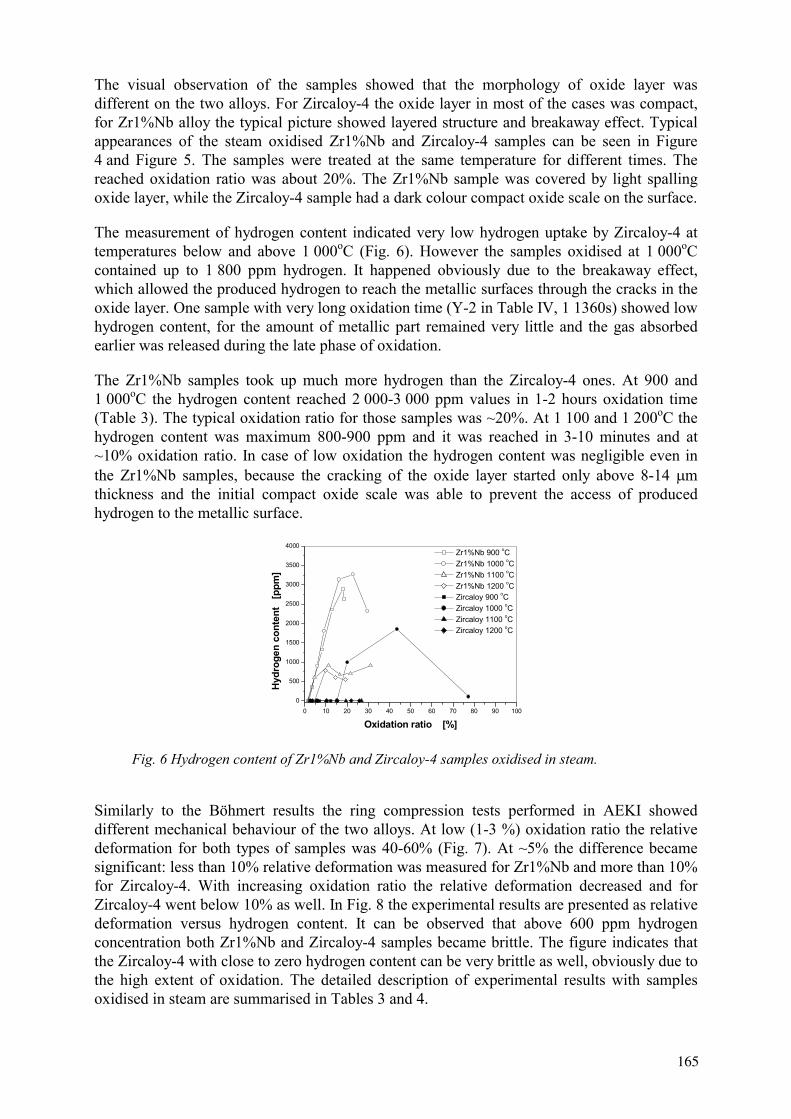
The measurement of hydrogen content indicated very low hydrogen uptake by Zircaloy-4 at temperatures below and above 1 000oC (Fig. 6). However the samples oxidised at 1 000oCcontained up to 1 800 ppm hydrogen. It happened obviously due to the breakaway effect, which allowed the produced hydrogen to reach the metallic surfaces through the cracks in the oxide layer. One sample with very long oxidation time (Y-2 in Table IV, 1 1360s) showed low hydrogen content, for the amount of metallic part remained very little and the gas absorbed earlier was released during the late phase of oxidation.
The Zr1%Nb samples took up much more hydrogen than the Zircaloy-4 ones. At 900 and 1 000oC the hydrogen content reached 2 000-3 000 ppm values in 1-2 hours oxidation time (Table 3). The typical oxidation ratio for those samples was ~20%. At 1 100 and 1 200oC the hydrogen content was maximum 800-900 ppm and it was reached in 3-10 minutes and at ~10% oxidation ratio. In case of low oxidation the hydrogen content was negligible even in the Zr1%Nb samples, because the cracking of the oxide layer started only above 8-14 mthickness and the initial compact oxide scale was able to prevent the access of produced hydrogen to the metallic surface.
0 10 20 30 40 50 60 70 80 90 1000
500
1000
1500
2000
2500
3000
3500
4000 Zr1%Nb 900 oC Zr1%Nb 1000 oC Zr1%Nb 1100 oC Zr1%Nb 1200 oC Zircaloy 900 oC Zircaloy 1000 oC Zircaloy 1100 oC Zircaloy 1200 oC
Hydr
ogen
con
tent
[p
pm]
Oxidation ratio [%]
Fig. 6 Hydrogen content of Zr1%Nb and Zircaloy-4 samples oxidised in steam.
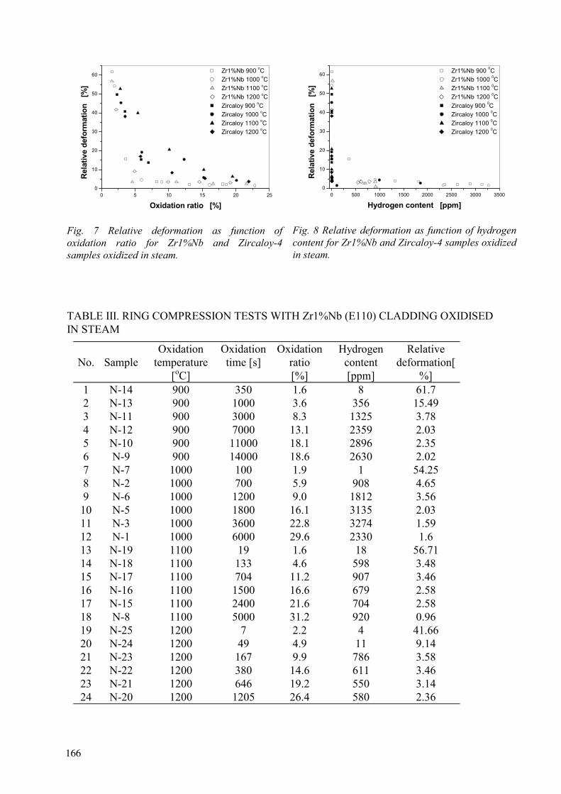
Similarly to the Böhmert results the ring compression tests performed in AEKI showed different mechanical behaviour of the two alloys. At low (1-3 %) oxidation ratio the relative deformation for both types of samples was 40-60% (Fig. 7). At ~5% the difference became significant: less than 10% relative deformation was measured for Zr1%Nb and more than 10% for Zircaloy-4. With increasing oxidation ratio the relative deformation decreased and for Zircaloy-4 went below 10% as well. In Fig. 8 the experimental results are presented as relative deformation versus hydrogen content. It can be observed that above 600 ppm hydrogen concentration both Zr1%Nb and Zircaloy-4 samples became brittle. The figure indicates that the Zircaloy-4 with close to zero hydrogen content can be very brittle as well, obviously due to the high extent of oxidation. The detailed description of experimental results with samples oxidised in steam are summarised in Tables 3 and 4.
165
0 5 10 15 20 250
10
20
30
40
50
60 Zr1%Nb 900 oC Zr1%Nb 1000 oC Zr1%Nb 1100 oC Zr1%Nb 1200 oC Zircaloy 900 oC Zircaloy 1000 oC Zircaloy 1100 oC Zircaloy 1200 oC
Rela
tive
defo
rmat
ion
[%
]
Oxidation ratio [%]
Fig. 7 Relative deformation as function of oxidation ratio for Zr1%Nb and Zircaloy-4 samples oxidized in steam.
0 500 1000 1500 2000 2500 3000 35000
10
20
30
40
50
60 Zr1%Nb 900 0C Zr1%Nb 1000 0C Zr1%Nb 1100 0C Zr1%Nb 1200 0C Zircaloy 900 0C Zircaloy 1000 0C Zircaloy 1100 0C Zircaloy 1200 0C
Rel
ativ
e de
form
atio
n [
%]
Hydrogen content [ppm]
Fig. 8 Relative deformation as function of hydrogen content for Zr1%Nb and Zircaloy-4 samples oxidized in steam.
TABLE III. RING COMPRESSION TESTS WITH Zr1%Nb (E110) CLADDING OXIDISED IN STEAM
No. Sample Oxidation
temperature [oC]
Oxidation time [s]
Oxidation ratio [%]
Hydrogen content[ppm]
Relative deformation[
%] 1 N-14 900 350 1.6 8 61.7 2 N-13 900 1000 3.6 356 15.49 3 N-11 900 3000 8.3 1325 3.78 4 N-12 900 7000 13.1 2359 2.03 5 N-10 900 11000 18.1 2896 2.35 6 N-9 900 14000 18.6 2630 2.02 7 N-7 1000 100 1.9 1 54.25 8 N-2 1000 700 5.9 908 4.65 9 N-6 1000 1200 9.0 1812 3.56
10 N-5 1000 1800 16.1 3135 2.03 11 N-3 1000 3600 22.8 3274 1.59 12 N-1 1000 6000 29.6 2330 1.6 13 N-19 1100 19 1.6 18 56.71 14 N-18 1100 133 4.6 598 3.48 15 N-17 1100 704 11.2 907 3.46 16 N-16 1100 1500 16.6 679 2.58 17 N-15 1100 2400 21.6 704 2.58 18 N-8 1100 5000 31.2 920 0.96 19 N-25 1200 7 2.2 4 41.66 20 N-24 1200 49 4.9 11 9.14 21 N-23 1200 167 9.9 786 3.58 22 N-22 1200 380 14.6 611 3.46 23 N-21 1200 646 19.2 550 3.14 24 N-20 1200 1205 26.4 580 2.36
166

TABLE IV. RING COMPRESSION TESTS WITH ZIRCALOY-4 CLADDING OXIDISED IN STEAM
No.Sample
Oxidation temperature
[oC]
Oxidation time [s]
Oxidation ratio [%]
Hydrogen cont
[ppm]
Relative def. [%]
1 Y-11 900 300 2.3 3 49.63 2 Y-10 900 1000 3.5 2 40.77 3 Y-8 900 5000 5.9 2 15.37 4 Y-9 900 11000 7 1 13.71 5 Y-6 1000 87 2.9 1 45.34 6 Y-5 1000 464 6 1 19.17 7 Y-1 1000 2600 12.3 1 15.43 8 Y-7 1000 3300 15.2 8 5.83 9 Y-4 1000 4090 20.1 997 4.33
10 Y-3 1000 7270 43.6 1854 2.72 11 Y-2 1000 11360 77.3 110 1.48 12 Y-17 1100 27 2.8 1 52.68 13 Y-16 1100 102 5.4 1 39.91 14 Y-15 1100 398 10.1 3 20.66 15 Y-14 1100 900 15.2 2 10 16 Y-13 1100 1500 19.5 2 6.4 17 Y-12 1100 3000 26.8 5 4.65 18 Y-23 1200 10 3.5 1 38.17 19 Y-22 1200 40 5.8 1 17.07 20 Y-21 1200 163 10.5 1 8.46 21 Y-20 1200 367 15.4 1 5.42 22 Y-18 1200 790 21.9 5 3.75 23 Y-19 1200 1100 25.7 1 3.75
4. CONCLUSIONS
The results of the described experiments provided detailed information on the effect of hydrogen and oxygen content on the embrittlement of zirconium alloys. The studies of the separate effect of oxygen and hydrogen make the clearing up of their roles in the embrittlement process possible. The most important conclusions were the followings:
Hydrogen seems to play a more important role in embrittlement of zirconium alloys than oxygen. The changes of mechanical properties of the oxidised Zr cladding can be reasonable explained by the hydrogen uptake rather than by the oxygen content. The combined effect of high hydrogen and oxygen contents in the Zr alloys leads to faster degradation of mechanical properties, than any of the separate hydrogen or oxygen effect. The embrittlement process caused by hydrogen uptake starts in Zircaloy-4 at lower hydrogen content than in Zr1%Nb. Under steam oxidation conditions the Zr1%Nb alloy takes up much more hydrogen than the Zircaloy-4 and it results in the embrittlement of higher level. This explains the observed difference in ring compression tests with E110 (Zr1%Nb) and Zry-4 claddings.
167

The experimental results confirmed the differences between Zr1%Nb and Zircaloy observed by Böhmert [1]. New data published on M5 alloy [6] indicated that this new niobium containing material does not show the increased embrittlement during steam oxidation and so contradicts the Böhmert and AEKI experiments. It means that the niobium content was not the real reason for the different behaviour of the two claddings, but other reasons should be identified.
REFERENCES
[1] FRECSKA, KONCZOS, G., MARÓTI, L., MATUS, L.,: Oxidation and Hydriding of Zr1%Nb Alloy by Steam.KFKI-1995-17/G Report
[2] FRECSKA, MATUS, L., VASÁROS, L., MARÓTI L.,: Hydrogen uptake of Zr1%Nb cladding by steam oxidation during loss of coolant accident, IAEA research contract 9284/R0, Final report, 1997
[3] SVÁB, MÉSZÁROS, GY., SOMOGYVÁRI, Z., BALASKÓ, M., K RÖSI F.,: Neutron Imaging of Zr1%Nb Cladding Material Containing Hydrogen, Applied Radiation and Isotopes (to be published)
[4] BÖHMERT, DIETRICH,M., LINEK J.,: Comparative analysis of high temperature corrosion of ZrNb1 and Zircaloy-4, Nucl. Eng. Design, 147(1993), pp. 53-62
[5] GRIGER, MARÓTI, L., MATUS, L., and WINDBERG, P.,: Ambient and high temperature mechanical properties of Zr1%Nb cladding with different oxygen and hydrogen content, HPR-351/35,1999, Loen
[6] SOLYANY, I., BIBLIASHVILI, YU. K., DRANENKO, V. V., LEVIN, A YA., B.IZRALJEVSKIJ, L., M. MOROZOV A,: Steam Oxidation of Zr1%Nb Clads of VVER Fuels at High Temperature. Proc. Specialists’ Meeting of IAEA, Bowness-on-Windermere, 1984. IAEA-IWGFPT/19, Vienna 1984
[7] LEISTIKOW, SCHANZ G.,: Werkstoffe und Korrosion, 36. 105-116. (1985) [8] MARDON, FRICHET, A., LE BOURHIS A.,: Behaviour of M5 alloy under normal and
accident conditions, TOPFUEL 2001, 27-30 May, Stockholm
168
WWER-1000 TYPE FUEL ASSEMBLY TESTS ONELECTROHEATED FACILITIES IN LOCA SIMULATING CONDITIONS
YU.K. BIBILASHVILI, N.B. SOKOLOV, A.V. SALATOV, V.Yu. TONKOV,P.V. FEDOTOV, L.N. ANDREEVA-ANDRIEVSKAYA, A.A. Bochvar All-Russia Research Institute of Inorganic Materials, VNIINM, Russian Federation
V.P. DENISKIN, V.I. NALIVAEV, N.Ya. PARSHIN,P.G. AFANASYEV, V.S. KONSTANTINOV Science Industrial Association "LUCH", Russian Federation
V.P. SEMISHKIN, A.M. SHUMSKIExperimental and Design Organisation “GIDROPRESS”, Russian Federation
Abstract. The results of tests with 19- and 37-element WWER-1000 type fuel assemblies (FAs) on the electroheated facility under loss-of-coolant conditions are presented. The temperature-force loading conditions were varied in the tests. Zr1%Nb and E635 alloys were used as a cladding material. The data on the cladding deformation state and FA cross section blockage are submitted.
1 INTRODUCTION
LWR fuel oxidation, fuel rod claddings deformation and FA cross section blockage are characteristic of loss-of-coolant accidents. The results of experimental studies of these questions with the use of models of Zry-4 fuel rod claddings FAs were published in [1-3].
In Russia the integral experiments with 19- and 37-element WWER type assemblies are carried out on electroheated facilities PARAMETR-M (SIA "Luch") and TEFSAI-19 (VNIINM). The works are financed by TVEL stock company.
The main variable parameters of the experiments are as follows:
- test scenario (heating rate, maximum fuel rod cladding temperature, steam flow rate, presence or absence of quenching, etc.);
- fuel rod cladding material.
The aims of the tests on electroheated facilities and post-test research are:
- investigation of the temperature-force loading parameters, corresponding to different thermo-hydraulic LB-LOCA scenarios, influence on the assemblies damage characteristics;
- research of deformation behaviour of the fuel rod simulator claddings gathered in an assembly and their depressurization parameters (temperature, pressure, deformations and coordinates of places of rupture);
- definition of the FA cross section blockage and cladding balloonings distribution along the assembly height.
Verification of the codes used to design WWER-type reactors is an important goal of the integral experiments. The results of the experiments presented are used for verification of the RAPTA-5 code [4,5,]. Verification of the RAPTA-5 models of E635 claddings deformation and oxidation is going on now.
169

2 EXPERIMENTAL TECHNIQUE
The scheme of the WWER-type 37-element electroheated experimental FA (PARAMETR-M facility) is shown in Fig.1, the schemes of the electroheated and passive fuel rod simulators are presented in Fig.2.
The FA is placed in the hexagonal Zr1%Nb shroud and thermal insulation of porous ZrO2.
In the 37-element assembly the central simulator and 12 simulators of the second row are passive, while 6 simulators of the first row and 18 of the fourth are electroheated by means of the central tungsten electrode.
The 19-element assemblies tested on the PARAMETR and TEFSAI-19 facilities have a similar construction [5]. All the fuel rod simulators of the 19-element assembly are electroheated.
Indications of the claddings thermocouples and the internal pressure transducers were recorded during the experiments. After the experiments the FAs were dismantled and the claddings cross-section perimeters were measured.
The logarithmic strains and the claddings conditional radiuses were determined by the formulas:
= ln ( / o ) R = Ro exp ( )
where
o, initial and conditional perimeters of the cladding outer surface, Ro, R initial and conditional radius of the cladding outer surface radiuses.
The perimeter includes the crack width; the conditional radius is determined in assumption of the claddings cross-section being round, thus obtaining a conservative estimation of the cross-section area.
The calculated estimation of the hexagonal cell (for one fuel rod) cross section blockage was determined using equation:
Bsingl = (R2 - R02)/(
23 Hgr
2 - R02 ) * 100%,
where
Hgr is the pitch of the spacing grid (of the fuel rods disposition in the assembly).
170
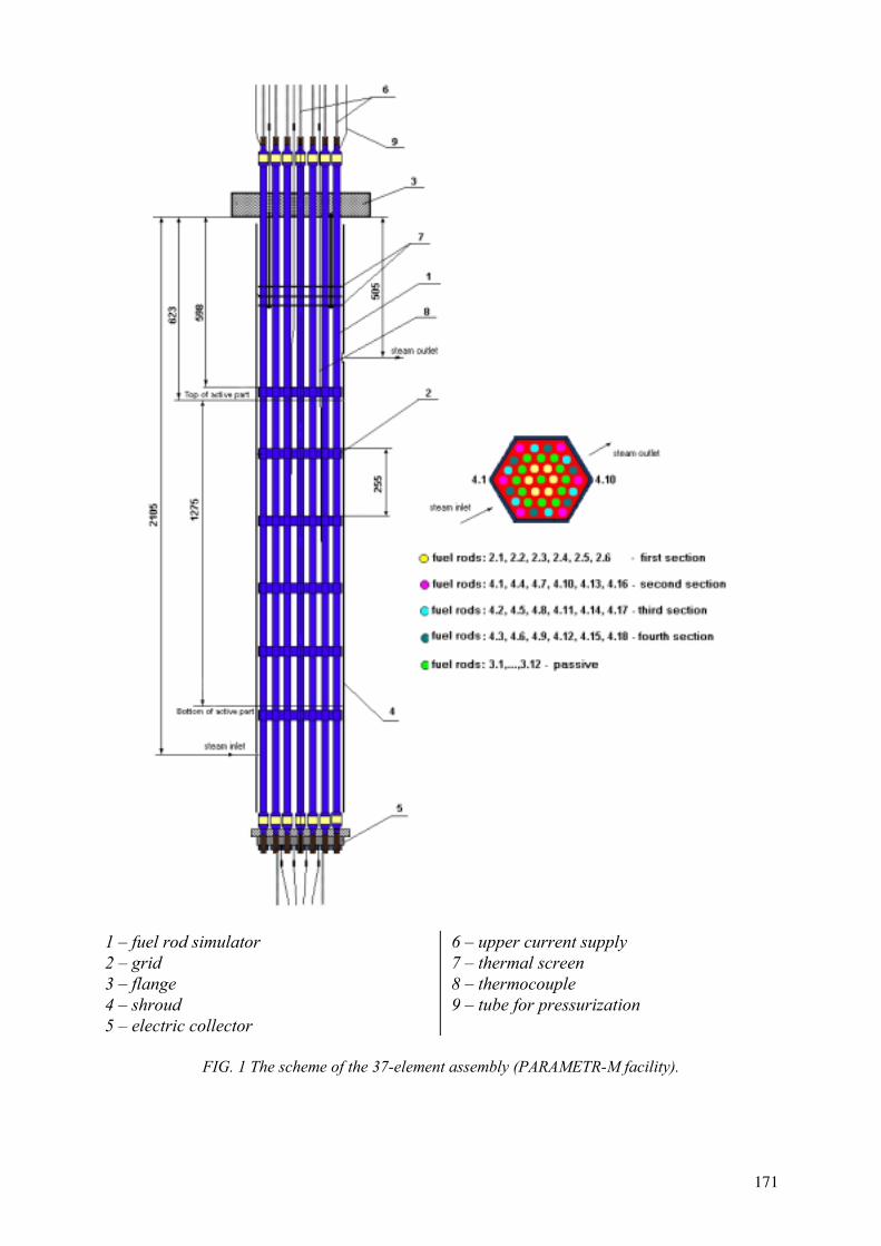
1 – fuel rod simulator 2 – grid 3 – flange 4 – shroud 5 – electric collector
6 – upper current supply 7 – thermal screen 8 – thermocouple 9 – tube for pressurization
FIG. 1 The scheme of the 37-element assembly (PARAMETR-M facility).
171
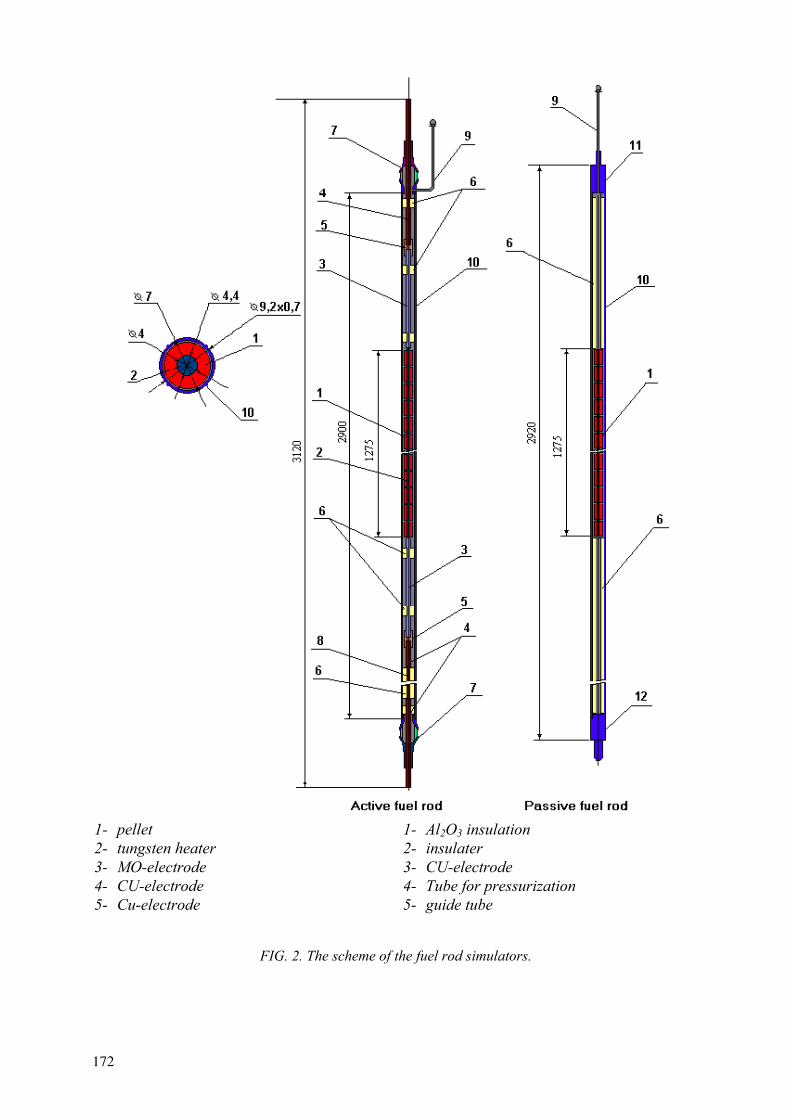
1- pellet 2- tungsten heater 3- MO-electrode 4- CU-electrode 5- Cu-electrode
1- Al2O3 insulation 2- insulater 3- CU-electrode 4- Tube for pressurization 5- guide tube
FIG. 2. The scheme of the fuel rod simulators.
172
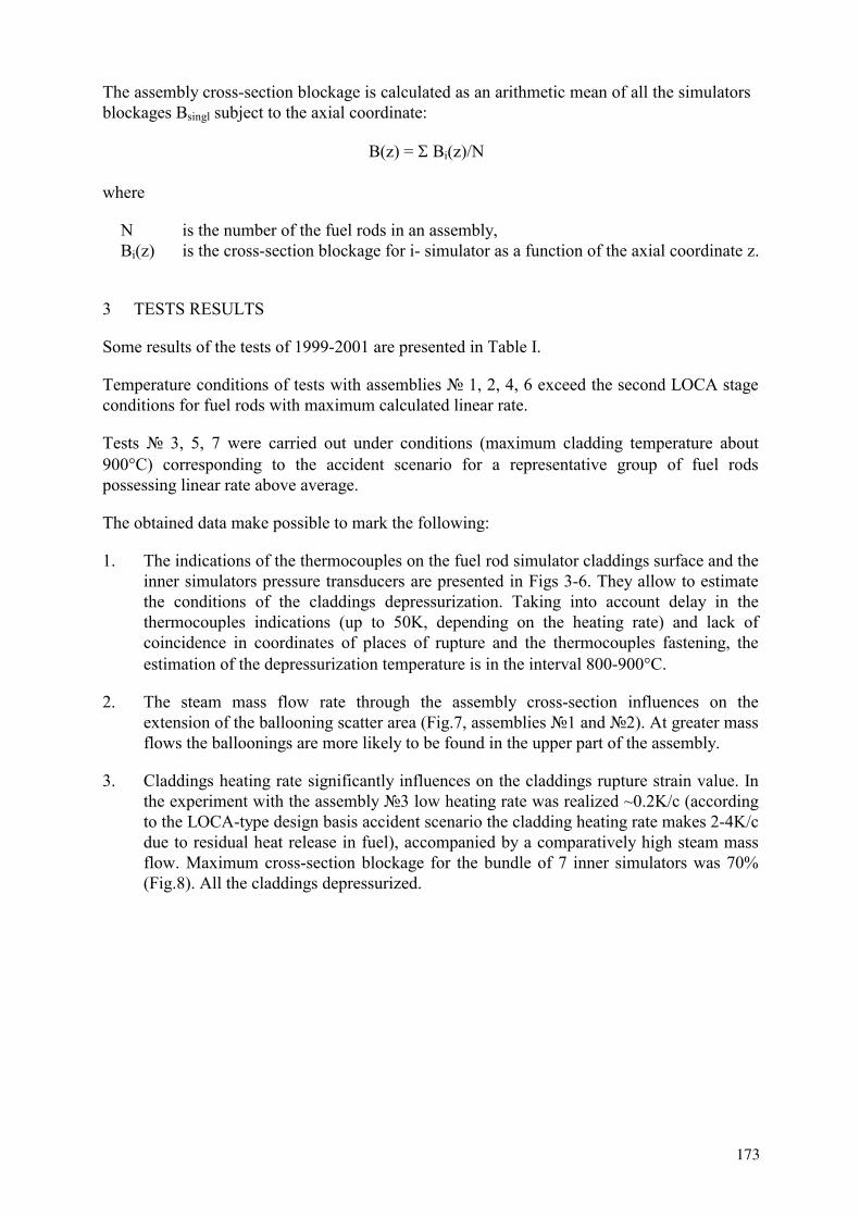
The assembly cross-section blockage is calculated as an arithmetic mean of all the simulators blockages Bsingl subject to the axial coordinate:
B(z) = Bi(z)/N
where
N is the number of the fuel rods in an assembly, Bi(z) is the cross-section blockage for i- simulator as a function of the axial coordinate z.
3 TESTS RESULTS
Some results of the tests of 1999-2001 are presented in Table I.
Temperature conditions of tests with assemblies 1, 2, 4, 6 exceed the second LOCA stage conditions for fuel rods with maximum calculated linear rate.
Tests 3, 5, 7 were carried out under conditions (maximum cladding temperature about 900 C) corresponding to the accident scenario for a representative group of fuel rods possessing linear rate above average.
The obtained data make possible to mark the following:
1. The indications of the thermocouples on the fuel rod simulator claddings surface and the inner simulators pressure transducers are presented in Figs 3-6. They allow to estimate the conditions of the claddings depressurization. Taking into account delay in the thermocouples indications (up to 50K, depending on the heating rate) and lack of coincidence in coordinates of places of rupture and the thermocouples fastening, the estimation of the depressurization temperature is in the interval 800-900 C.
2. The steam mass flow rate through the assembly cross-section influences on the extension of the ballooning scatter area (Fig.7, assemblies 1 and 2). At greater mass flows the balloonings are more likely to be found in the upper part of the assembly.
3. Claddings heating rate significantly influences on the claddings rupture strain value. In the experiment with the assembly 3 low heating rate was realized ~0.2K/c (according to the LOCA-type design basis accident scenario the cladding heating rate makes 2-4K/c due to residual heat release in fuel), accompanied by a comparatively high steam mass flow. Maximum cross-section blockage for the bundle of 7 inner simulators was 70% (Fig.8). All the claddings depressurized.
173
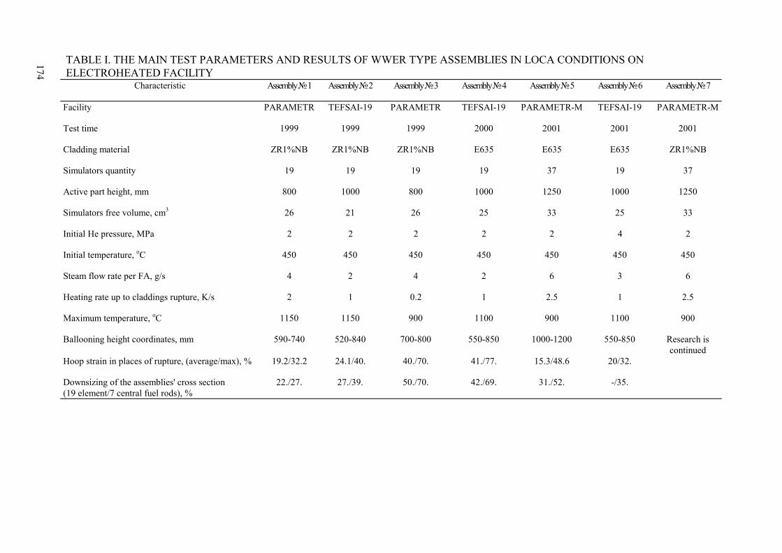
TABLE I. THE MAIN TEST PARAMETERS AND RESULTS OF WWER TYPE ASSEMBLIES IN LOCA CONDITIONS ON ELECTROHEATED FACILITY
Characteristic Assembly 1 Assembly 2 Assembly 3 Assembly 4 Assembly 5 Assembly 6 Assembly 7
Facility PARAMETR TEFSAI-19 PARAMETR TEFSAI-19 PARAMETR-M TEFSAI-19 PARAMETR-M
Test time 1999 1999 1999 2000 2001 2001 2001
Cladding material ZR1%NB ZR1%NB ZR1%NB E635 E635 E635 ZR1%NB
Simulators quantity 19 19 19 19 37 19 37
Active part height, mm 800 1000 800 1000 1250 1000 1250
Simulators free volume, cm3 26 21 26 25 33 25 33
Initial He pressure, MPa 2 2 2 2 2 4 2
Initial temperature, oC 450 450 450 450 450 450 450
Steam flow rate per FA, g/s 4 2 4 2 6 3 6
Heating rate up to claddings rupture, K/s 2 1 0.2 1 2.5 1 2.5
Maximum temperature, oC 1150 1150 900 1100 900 1100 900
Ballooning height coordinates, mm 590-740 520-840 700-800 550-850 1000-1200 550-850 Research is continued
Hoop strain in places of rupture, (average/max), % 19.2/32.2 24.1/40. 40./70. 41./77. 15.3/48.6 20/32.
Downsizing of the assemblies' cross section (19 element/7 central fuel rods), %
22./27. 27./39. 50./70. 42./69. 31./52. -/35.
174

A) Claddings' thermocouple indications in hot zone.
4200 4400 4600 4800 5000 5200 5400 5600 5800Time, s
400
600
800
1000
1200Te
mpe
ratu
re, C
B) Simulators' pressure transducer indications.
4200 4400 4600 4800 5000 5200 5400 5600 5800Time, s
0
1
2
3
4
5
Pre
ssur
e, M
Pa
Fig. 3 Assembly 1 test conditions (Zr1%Nb alloy).
175
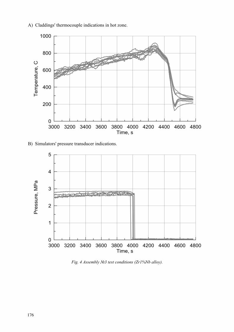
A) Claddings' thermocouple indications in hot zone.
3000 3200 3400 3600 3800 4000 4200 4400 4600 4800Time, s
0
200
400
600
800
1000Te
mpe
ratu
re, C
B) Simulators' pressure transducer indications.
3000 3200 3400 3600 3800 4000 4200 4400 4600 4800Time, s
0
1
2
3
4
5
Pre
ssur
e, M
Pa
Fig. 4 Assembly 3 test conditions (Zr1%Nb alloy).
176
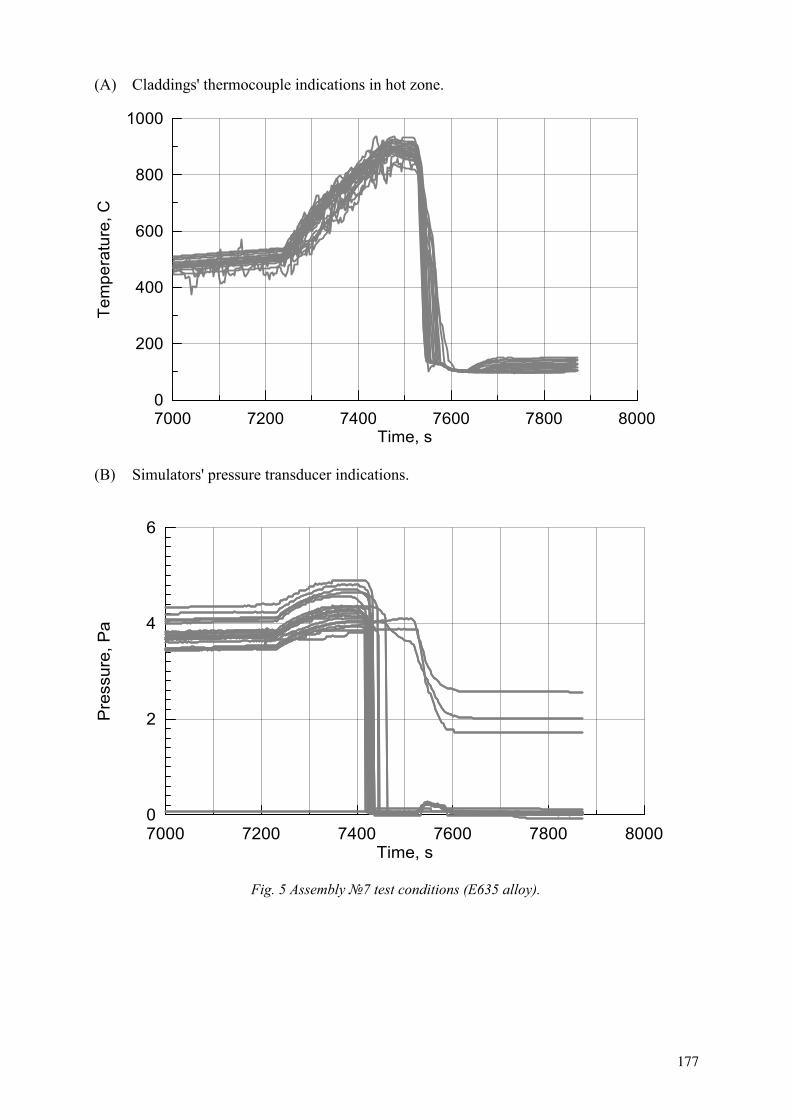
(A) Claddings' thermocouple indications in hot zone.
7000 7200 7400 7600 7800 8000Time, s
0
200
400
600
800
1000Te
mpe
ratu
re, C
(B) Simulators' pressure transducer indications.
7000 7200 7400 7600 7800 8000Time, s
0
2
4
6
Pre
ssur
e, P
a
Fig. 5 Assembly 7 test conditions (E635 alloy).
177

(A) Claddings' thermocouple indications in hot zone.
6000 6200 6400 6600 6800 7000Time, s
0
200
400
600
800
1000Te
mpe
ratu
re, C
(B) Simulators' pressure transducer indications.
6000 6200 6400 6600 6800 7000Time, s
0
2
4
6
Pre
ssur
e, M
Pa
Fig 6. Assembly 5 test conditions (E635 alloy).
178
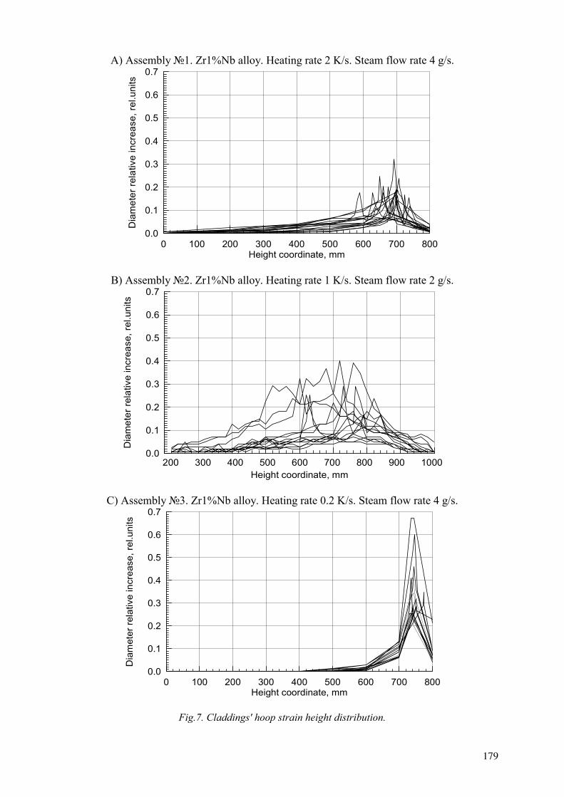
A) Assembly 1. Zr1%Nb alloy. Heating rate 2 K/s. Steam flow rate 4 g/s.
0 100 200 300 400 500 600 700 800Height coordinate, mm
0.0
0.1
0.2
0.3
0.4
0.5
0.6
0.7
Dia
met
er re
lativ
e in
crea
se, r
el.u
nits
B) Assembly 2. Zr1%Nb alloy. Heating rate 1 K/s. Steam flow rate 2 g/s.
Height coordinate, mm
0.0
0.1
0.2
0.3
0.4
0.5
0.6
0.7
Dia
met
er re
lativ
e in
crea
se, r
el.u
nits
200 300 400 500 600 700 800 900 1000
C) Assembly 3. Zr1%Nb alloy. Heating rate 0.2 K/s. Steam flow rate 4 g/s.
0 100 200 300 400 500 600 700 800Height coordinate, mm
0.0
0.1
0.2
0.3
0.4
0.5
0.6
0.7
Dia
met
er re
lativ
e in
crea
se, r
el.u
nits
Fig.7. Claddings' hoop strain height distribution.
179
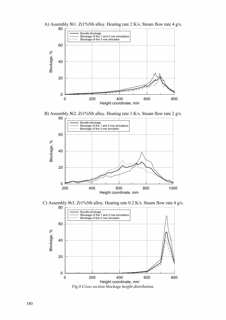
A) Assembly 1. Zr1%Nb alloy. Heating rate 2 K/s. Steam flow rate 4 g/s.
0 200 400 600 800Height coordinate, mm
0
20
40
60
80
Blo
ckag
e, %
Bundle blockageBlockage of the 1 and 2 row simulatorsBlockage of the 3 row simulator
B) Assembly 2. Zr1%Nb alloy. Heating rate 1 K/s. Steam flow rate 2 g/s.
200 400 600 800 1000Height coordinate, mm
0
20
40
60
80
Blo
ckag
e, %
Bundle blockageBlockage of the 1 and 2 row simulatorsBlockage of the 3 row simulator
C) Assembly 3. Zr1%Nb alloy. Heating rate 0.2 K/s. Steam flow rate 4 g/s.
0 200 400 600 800Height coordinate, mm
0
20
40
60
80
Blo
ckag
e, %
Bundle blockageBlockage of the 1 and 2 row simulatorsBlockage of the 3 row simulator
Fig.8 Cross section blockage height distribution.
180

A) Assembly 4. E635 alloy. Initial internal pressure 2Mpa.
0 200 400 600 800 1000Height coordinate, mm
0.0
0.1
0.2
0.3
0.4
0.5
0.6
0.7
Dia
met
er re
lativ
e in
crea
se, r
el.u
nits
B) Assembly 6. E635 alloy. Initial internal pressure 4 MPa (7 central simulators).
0 200 400 600 800 1000Height coordinate, mm
0.0
0.1
0.2
0.3
0.4
0.5
0.6
0.7
Dia
met
er re
lativ
e in
crea
se, r
el.u
nits
Fig. 9 Claddings hoop strain height distribution.
181
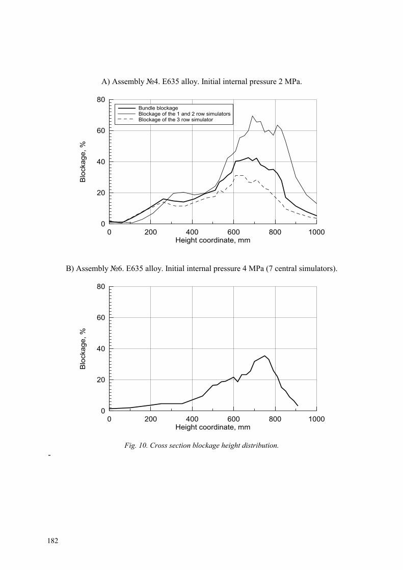
A) Assembly 4. E635 alloy. Initial internal pressure 2 MPa.
0 200 400 600 800 1000Height coordinate, mm
0
20
40
60
80
Blo
ckag
e, %
Bundle blockageBlockage of the 1 and 2 row simulatorsBlockage of the 3 row simulator
B) Assembly 6. E635 alloy. Initial internal pressure 4 MPa (7 central simulators).
0 200 400 600 800 1000Height coordinate, mm
0
20
40
60
80
Blo
ckag
e, %
Fig. 10. Cross section blockage height distribution. -
182

Assembly 1. Zr1%Nb alloy. Simulator 2.1
0 100 200 300 400 500 600 700 800 900 1000
Height coordinate, mm
100
200
300
400
500
600
Mic
roha
rdne
ss H
, k
g/m
m50
2
Fig. 11 Post-test appearance of the cladding and microstructure in the place of rupture; cladding height microhardness distribution. Assembly 1. Zr1%Nb alloy. Simulator 2.1.
183

A) Assembly 5, E635 alloy.
B) Assembly 7, Zr1%Nb alloy.
Fig. 12. Post-test appearance of the cladding in the place of rupture.
Tests on two 19-element assemblies with Zr1%Nb and E635 claddings ( 2 and 4) in similar conditions revealed higher plasticity of E635 claddings (Fig.7,b and Fig.9,a). Maximum cross-section blockage for the bundle of 7 inner simulators of E635 assembly 4did not exceed 69%.
4. In test on assembly 6 with E635 claddings with excess inner pressure (simulation of burn-up effects) lower rupture deformation and cross-section blockage values were received, than in case of assembly 4 (Fig.9,10).
5. Depressurization of all the claddings in tests with assemblies 1,2,4,6 was present (maximum cladding temperature 1 150 C and 1 100 C).
6. Tests on two 37-element assemblies with Zr1%Nb and E635 claddings ( 5 and 7)were carried out under conditions typical of the second stage of the accident (heating due to residual heat release in fuel) for the representative group of heat-stressed fuel rods (Fig.5,6). The distinctive feature of these assemblies construction is presence of passive fuel rods (1 central + 12 fuel rods of the third row). The passive simulators claddings temperature in the hot area was substantially lower (approximately 100K), than the electroheated fuel rods temperature. In the experiment with assembly 7(Zr1%Nb) all, but three claddings depressurized. In the experiment with assembly 5(E635) none of the passive fuel rods lost tightness. The post-test research of the tested 37-element assemblies has not been completed yet.
7. All the assemblies kept the integrity after the tests, despite that in the test they were quenched with cold water (except assembly 1). The simulator claddings survived disassembly and kept the integrity. The appearance , microstructure, microhardness distribution along the assembly 1 fuel rod cladding height are shown in Fig.11. This assembly was tested at maximum temperature 1150 C. The appearances of fuel rod simulators claddings of E635 and Zr1%Nb alloys (assemblies 5 and 7correspondingly) tested at maximum temperature 900 C, is presented in Fig.12.
184

4 CONCLUSIONS
The tests with 19- and 37-element WWER-1000 type experimental FAs with Zr1%Nb and E635 claddings on the electroheated facilities under conditions, typical of the second stage of the loss-of-coolant accidents, at different heating and coolant flow rates have been completed.
All the claddings kept the integrity and did not fragment during the experiments or disassembling.
The fuel rod simulators claddings depressurization takes place at the stage of heating in the temperature range 800-900 C. Therefore in case of the experiments with the most conservative scenario at maximum temperature 1 100-1 150 C the depressurization is inevitable.
In experiments according to the scenario for the representative group of heat-strained WWER-1000 fuel rods not all claddings depressurized. In the temperature range 800-900 C the claddings depressurization is determined by the specific temperature dependence and pressure. E635 claddings performed higher viability, than those of Zr1%Nb alloy.
The conservative estimations of the cross-section blockage for all tested assemblies with Zr1%Nb and E635 claddings do not exceed 70%.
A) Assembly 4. E635 alloy. Initial internal pressure 2 MPa.
REFERENCES
[1] KAWASAKI, S., UETSUKA, H., FURUTA, T., Multirods burst tests under loss-of-coolant conditions. In: OECD-NEA-CSNI/IAEA Specialists' Meeting on Water Reactor Fuel Safety and Fission Product Release in Off-Normal and Accident Conditions. Riso, Denmark, 16-20 May 1983, IWGEPT/16, pp.17-28.
[2] ERBACHER, F.J., NEITZEL, H.J., WEIHR, K., Effects of thermohydraulics on clad ballooning, flow blockage and coolability in a LOCA. Ibid./1/, pp.29-37.
[3] HINDLE, E.D., JONES, C., WHITTY S., Measurement of blockage in deformed LWR multi-rod arrays. Ibid./1/, pp.70-80.
[4] BIBILASHVILI, YU, SOKOLOV, N., SALATOV, A., ANDREEVA-ANDRIEVSKAYA, L., NECHAEVA, O., FEDOTOV, P., NALIVAEV, V., AFANASYEV, P., KONSTANTINOV, V., PARSHIN, N., SEMISHKIN, V., SHUMSKI, A., SMIRNOV, V., KUNGURTZEV, I., KOSVINTZEV, YU., Experimental Researches and Modelling of WWER Fuel Rods' Behaviour in LOCA Conditions using RAPTA-5 Code. Third International Seminar on WWER Fuel Performance, Modelling and Experimental Support, Pamporovo, Bulgaria, 4-8 October 1999, pp.221-228.
[5] BIBILASHVILI, YU., SOKOLOV, N., SALATOV, A., TONKOV, V., ANDREEVA-ANDRIEVSKAYA, L., FEDOTOV, P., NALIVAEV, V., AFANASYEV, P., KONSTANTINOV, V., PARSHIN, N., SEMISHKIN, V., SHUMSKI, A., WWER Type Fuel Rod Bundle Tests in LOCA Simulation Conditions. 6th International QUENCH Workshop, Germany, Karlsruhe, 10-12, 2000.
185

THERMOMECHANICAL PROPERTIES OF ZIRCONIUM-BASED ALLOYS OXIDIZED CLADDINGS IN LOCA SIMULATING CONDITIONS
Yu.K. BIBILASHVILI, N.B. SOKOLOV, L.N. ANDREEVA-ANDRIEVSKAYA,V.Yu. TONKOV, A.V. SALATOV All-Russia Research Institute of Inorganic Materials, VNIINM, Moscow, Russian Federation
A.M. MOROSOV All-Russia Heat Engineering Institute, VTI, Moscow, Russian Federation
V.P. SMIRNOV State Scientific Center Research Institute of Atomic Reactors, RIAR, Dimitrovgrad, Russian Federation
Abstract. The researchof Zr1%Nb and E635 fuel rod claddings of WWER type reactors behavior and characteristics in loading conditions simulating accidents with loss of coolant and active zone quenching experimental data are presented. The experimental data allow to estimate type and numerical value of the embrittlement criteria parameters in terms of claddings resistance during quenching and subsequent operations, viz., fuel rod claddings assemblies removing from the core and transportation. The relation for estimation of Zr1%Nb fuel rod claddings oxidation degree is recommended. The relation is conservative in temperature interval (900-1 200)0C and time of oxidation up to 900 sec in case of presence of hydrogen in steam, claddings deforming, irradiation. The thermal shock experiments under loading conditions simulating accidents with loss of coolant (temperature, environment, deforming, limitation of the cladding axial deforming, quenching rate, irradiation) data are presented. It is shown, that the mechanical characteristics of the oxidized claddings material (Zr1%Nb, E635) after thermal shock (impact elasticity, residual ductility, deflection) are sufficient to withstand quenching and for subsequent removing and transportation.
1. INTRODUCTION
The first stage of the embrittlement criterion substantiation for zircaloy type alloy and for Russian alloy Zr1%Nb was completed in the beginning of the 80th.
The second stage is carried out now. One of the reasons for rise of interest to works in this field is increase of fuel burnup up to 60-70 MW d/kgU.
On the first stage of the embrittlement criterion substantiation fuel burnup didn't exceed 40 MW d/kgU. Dangerous consequences of irradiation for the claddings stability under loss-of-coolant-accident (LOCA) conditions are as follows:
- changes (degradation) of the claddings mechanical properties; - changes in the fuel (release and deposition of fission gas release (FGR), change of the
material structure on the inner cladding surface fuel-cladding gap overlapping, etc.).
The second reason is appearance of new materials - Zr-based alloys ZIRLO, MDA, M5, E635 in Russia.
Moreover, we should mention, that a range of factors that influence the cladding thermal resistance such as cladding deforming, presence of the axial mechanical loading on the cladding, hydrogen content, have been either unsufficiently investigated or not taken into account.
186
The work in this field has been carried out since the 70th. The methods have been developed. They are improved according to the increase of understanding of the problem and new requirements to the fuel.
Now under VNIINM leadership the Programm of cladding behaviour under LOCA experimental research has been realized. It includes:
1) safety criteria substantiation for high-burnup fuel (Zr1%Nb alloy). The revision of the existing data base with the purpose of detection and investigation of unsufficiently explored characteristics of unirradiated Zr1%Nb claddings;
2) investigation of E635 alloy properties; 3) safety criteria substantiation for E635 alloy; 4) integral experiments with the purpose of investigation of fuel assembly (FA) elements
(claddings, spacer grids (SG)) deforming and rupture (depressurization), oxidation and thermal resistance (fragmentation). 19-elements (TEFSAI-19 rig - VNIINM) and 37-elements (PARAMETER rig - SRI RPA "Lutch") FA are tested.
2. EMBRITTLEMENT CRITERION
Under LOCA conditions, there may be a short period of time before the fuel rods are recovered with cooling water. During this period, the decay heat causes the fuel rods to undergo a temperature excursion, and Zr1%Nb fuel rod claddings may reach temperatures of about 1 200oC. Under such conditions they are intensively oxidized by steam. The degree of the claddings oxidation is governed by the level of temperature, pressure, time of oxidation, deformation and other factors.
Owing to the cladding material embrittlement the initial thermophisical and mechanical properties of Zr1%Nb alloy, characteristics of ductility change. Thickness of the claddings non-oxidized metal decreases.
At the stage of core flooding with cool water of emergency cooling system oxidized claddings are likely to fail under the action of thermal stresses.
The main design requirements placed on a fuel rod in LOCA are the feasibility of cooling down a fuel rod having a distorted cladding as well as disassembly (removal) of the core after the accident.
The former requirement limits the degree of cladding balloning (plastic deforming and rupture). The second one does not tolerate cladding fragmentation (brittle fracture).
The degree of the cladding material (Zr1%Nb alloy) - coolant interaction is stipulated by the maximal design limit of fuel rod damage in the Russia document of norms [1].
The cladding embrittlement criterion limits the local oxidation depth (equivalent cladding reacted (ECR)) and maximal temperature of cladding (peak cladding temperature (PCT)):
1) maximum temperature of cladding must not exceed 1 2000C; 2) maximum local depth of cladding oxidation is not to be higher than 18% of its original
thickness.
187

The conservative dependence [2] is recommended to be used for estimation of the claddings oxidation degree (oxygen weight gain).
The adherence to the criterion values ensures preservation of the fuel rod geometry. The cladding has to withstand thermal shock as well as dynamic loads effected by a fuel assembly (fuel rod) removal from the core, placing to a storage and subsequent transportation.
3. EXPERIMENTAL RESEARCH OF ZR1%NB CLADDINGS THERMAL RESISTANCE
The experimental research to justify the Zr1%Nb fuel rod cladding of WWER-type embrittlement criterion have been under way in Russia since the 70th. The experimental technique has been coordinated with the Chief Designer of the nuclear power plants with WWER-type reactor (OKB "Hydropresss") and the Regulatory Body of Russia (GAN).
The experimental research comprises two stages.
First - the research of Zr1%Nb alloy oxidation in steam with the purpose of defining the dependences conservatively describing the kinetics of Zr1%Nb alloy oxidation in a wide temperature range. The rate of "Zr1%Nb - steam" reaction was studied under the influence of several factors. They are: cladding deforming under the action of excessed internal or external pressure; presence of hydrogen, air, nitrogen additives in steam; the excessed steam pressure, steam-drop conditions of cooling, irradiation.
The second part of the research involved the experiments to assess the thermal resistance of oxidized claddings.
The heat resistance is assumed to be the cladding ability to withstand thermal-force loading under LOCA conditions and after it to preserve sufficient mechanical strength for subsequent manipulations with the FA (removal, transportation).
The objective of the thermal resistance experiments is ascertainment of minimum time of claddings oxidation and the corresponding degree of oxidation (ECR), resulting in the claddings failure: on quenching, during removal from the experimental facility, during disassembly, during handling.
4. HIGH TEMPERATURE OXIDATION
The experimental research of Zr1%Nb fuel rod claddings oxidation have been carried out for more than 15 years. The main results of the studies have been reported in papers and articles; the basic results and dependences are dealt with in [2].
The requirements to the oxidation experimental procedure are the following:
- indirect method of the specimens heating in accurately thermperature-controlled working zone;
- accurately controlled temperature field uniform along height and over radius of the specimens heating zone;
- possibility of ensuring of isothermal regimes at specified pressure and steam flow rate;
188

- quality and composition of steam (or other oxygen containing environment) must not change during the experiment;
- vertical arrangement of the specimen within the facility work zone; - careful degreasing of the simulators surfaces that will be oxidized; - high accuracy of specimen temperature measurements, despite formation of
substantially thick oxide films and possible deformation of the specimen; - use of experimentally defined simulators weight gain as oxidation reaction measure
(continuous weighting during the experiment).
4.1. Estimation of oxidation degree
The degree of Zr1%Nb claddings oxidation is estimated via weight gain ( m), or local depth of oxidation (ECR) value.
The local depth of the cladding oxidation (ECR) is understood as the total equivalent Zr-layer thickness (that would react with steam assuming that all locally absorbed oxygen goes on formation of stoichiometrical zirconium dioxide ZrO2) related to the initial cladding thickness. If the fuel rod cladding is depressurized, oxidation of both outer and inner surfaces of the cladding are taken into account.
The weight gain can be defined simultaneously with oxidation (the experimental weight gain), or by calculation using the dependence, derived on experimentally obtained data base (calculated weight gain).
The weight gain m and the local depth of oxidation ECR are related by the ratio [2]
ECR = N ( e/ o ) 100, %
where
No
e
the coefficient taking into account two side oxidation of the cladding, N = 2; initial thickness of the specimen, m;thickness of the equivalent layer (calculated Zr thickness, which goes on ZrO2formation), m.
It is to be pointed out that the specific weight gain of the cladding is found by dividing the weight gain by the square of the initial cladding surface. This gives a conservative estimation of the specific weight gain. Real oxidation area can be larger due to possible cladding deforming.
Relation for the ECR definition has a kind
ECR = N 4,355 10-2 m/ o , %
In the temperature range (900-1 200) and the oxidation time up to 900 sec the parabolic rate equation is recommended as a conservative one for assessment of the degree of Zr1%Nb claddings oxidation [2]
m = 920 exp (-10410/T) (1)
189

where
m specific weight gain, mg/ m2; temperature, K;
time, s
The experimental results have shown, that in the indicated temperature-time range the dependence (1) defines Zr1%Nb claddings weight gain with the safety margin for the cases: availability of hydrogen addition in steam; excessed steam pressure; fuel rod claddings deformation, irradiation and steam-drop cooling.
A large experimental data array was obtained using UNOPRO facility (Fig. 1) with continuously recorded weight gain of the specimen during the Zr-steam reaction [2].
Research of E635 alloy oxidation kinetics has begun not long ago. Some preliminary dependences have been obtained. They allow to estimate cladding degree of oxidation (weight gain) in water steam under atmospheric pressure in temperature range (700 – 1 200)oC. They do not take into account influence of such factors as irradiation, excessed steam pressure, presence of air or hydrogen additives.
Fig. 1 Scheme of UNOPRO facility heating modulus.
Fig. 2 illustrates smoothed "weight gain – time" curves obtained when studying the kinetics of Zr1%Nb and E635 alloys oxidation on facility continuously recording the specimen weight gain. The experimental data given in Fig. 2 represent the averaged values of weight gains.
Fig. 3 demonstrates the experimentally obtained values of the oxidation reaction rate constant, dependence (1) for Zr1%Nb alloy, as well as Zry-4 oxidation rate [17] and Baker - Just dependence obtained for zirconium.
1 specimen 2 Pt bowl for ZrO2 collecting 3 Pt suspender 4 working zone 5 Pt heater 6, 7 compensating heater 8 furnace shaft 9 frame 10 balance pan 11 liquid damper 12 scale-beam 13 Pt- Pt/Rh thermocouple
190
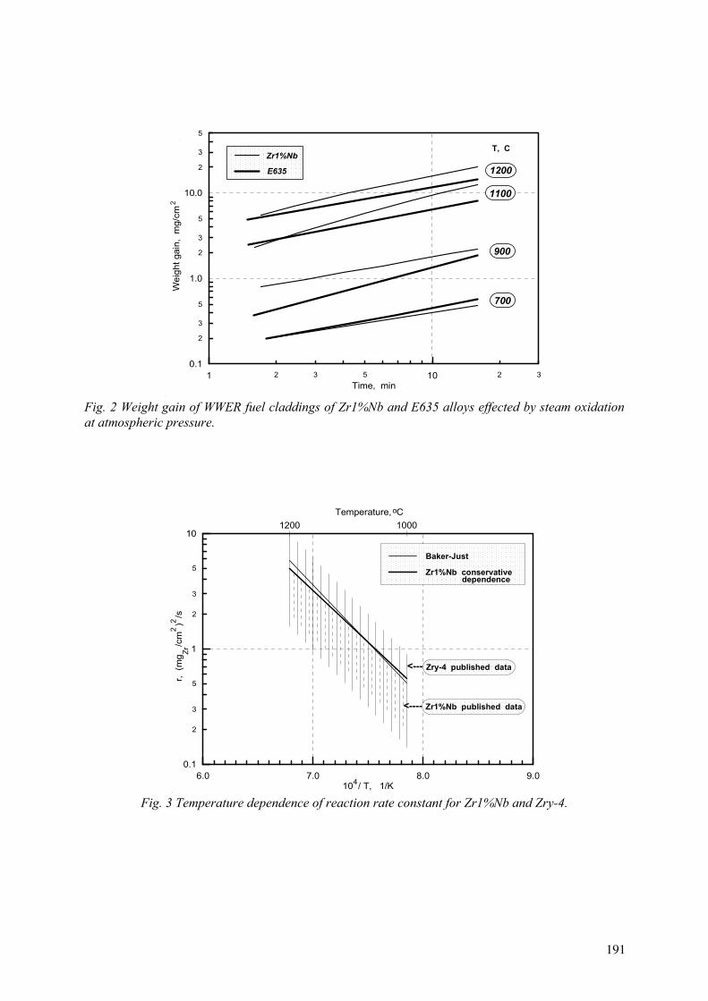
2 3 5 2 31 10Time, min
2
3
5
2
3
5
2
3
5
0.1
1.0
10.0
Wei
ght g
ain,
mg/
cm2
.
.
.
Zr1%Nb
E635
700
900
1100
1200
,
Fig. 2 Weight gain of WWER fuel claddings of Zr1%Nb and E635 alloys effected by steam oxidation at atmospheric pressure.
6.0 7.0 8.0 9.010 / T, 1/K
2
3
5
2
3
5
0.1
1
10
r, (m
g /
cm )
/s
.4
1200 1000 Temperature, Co
Zr2
2
Baker-Just
Zr1%Nb conservative
<---
<----
Zry-4 published data
Zr1%Nb published data
dependence
Fig. 3 Temperature dependence of reaction rate constant for Zr1%Nb and Zry-4.
191
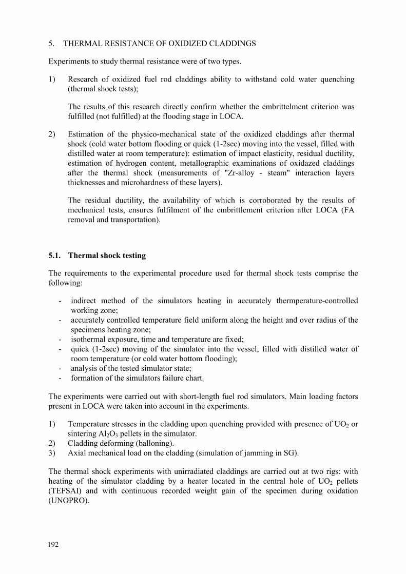
5. THERMAL RESISTANCE OF OXIDIZED CLADDINGS
Experiments to study thermal resistance were of two types.
1) Research of oxidized fuel rod claddings ability to withstand cold water quenching (thermal shock tests);
The results of this research directly confirm whether the embrittelment criterion was fulfilled (not fulfilled) at the flooding stage in LOCA.
2) Estimation of the physico-mechanical state of the oxidized claddings after thermal shock (cold water bottom flooding or quick (1-2sec) moving into the vessel, filled with distilled water at room temperature): estimation of impact elasticity, residual ductility, estimation of hydrogen content, metallographic examinations of oxidazed claddings after the thermal shock (measurements of "Zr-alloy - steam" interaction layers thicknesses and microhardness of these layers).
The residual ductility, the availability of which is corroborated by the results of mechanical tests, ensures fulfilment of the embrittlement criterion after LOCA (FA removal and transportation).
5.1. Thermal shock testing
The requirements to the experimental procedure used for thermal shock tests comprise the following:
- indirect method of the simulators heating in accurately thermperature-controlledworking zone;
- accurately controlled temperature field uniform along the height and over radius of the specimens heating zone;
- isothermal exposure, time and temperature are fixed; - quick (1-2sec) moving of the simulator into the vessel, filled with distilled water of
room temperature (or cold water bottom flooding); - analysis of the tested simulator state; - formation of the simulators failure chart.
The experiments were carried out with short-length fuel rod simulators. Main loading factors present in LOCA were taken into account in the experiments.
1) Temperature stresses in the cladding upon quenching provided with presence of UO2 or sintering Al2O3 pellets in the simulator.
2) Cladding deforming (balloning). 3) Axial mechanical load on the cladding (simulation of jamming in SG).
The thermal shock experiments with unirradiated claddings are carried out at two rigs: with heating of the simulator cladding by a heater located in the central hole of UO2 pellets (TEFSAI) and with continuous recorded weight gain of the specimen during oxidation (UNOPRO).
192

Thermal shock tests are carried out in a wide temperature range (900 – 1 300) . The degree of claddings oxidation was various (up to 60 % ECR).
The thermal resistance data for the WWER type Zr1%Nb fuel rod claddings, irradiated up to burnup of 46,2; 48,3; 49,5; 49,8 MW d/kgU were obtained.
The experiments with irradiated claddings were carried out on the universal rig designed to investigate the behaviour of core materials overheated above the operating temperatures in inert gas, air and steam-gas environments (UVS). The main element of the rig is the heating modulus (Fig. 4).
water
1
2
3
steam+Ar
410
5
6
7
steam+Ar
water
8
9
Fig. 4 General-purpose rig Scheme of the heating modulus.
The schemes of the simulators with unirradiated (type 1, 2, 3, 4) and irradiated undeformed claddings (type 5) used for thermal shock tests are given in Fig. 5.
The flooding rate values (or moving into the water) were chosen in view of the maximal conservatism of the received results (in terms of cladding ability to withstand thermal shock). It was shown in works [3, 4], that quick cooling causes larger stresses in the cladding during the thermal shock (in case of large oxidation degree especially).
The parameters of the thermal shock tests are listed in Table I.
1, 2 thermocouple 3 specimen withdrawal mechanism 4 Cylinder 5 Heating module 6 specimen 7 channel 8 water containing tank 9 specimen position after withdrawal 10 channel for the thermocouple
193
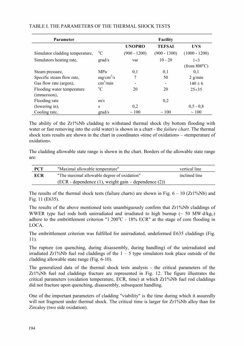
TABLE I. THE PARAMETERS OF THE THERMAL SHOCK TESTS
Parameter Facility UNOPRO TEFSAI UVS
Simulator cladding temperature, (900 - 1200) (900 - 1300) (1000 - 1200) Simulators heating rate, grad/s var 10 - 20 1 3
(from 800 )Steam pressure, MPa 0,1 0,1 0,1 Specific steam flow rate, mg/cm2/s 7 50 2 g/min Gas flow rate (argon), cm3/min - - 140 6 Flooding water temperature (immersion),
20 20 25 35
Flooding rate (lowering in),
m/s s 0,2
0,20,5 - 0,8
Cooling rate, grad/s ~ 100 ~ 100 ~ 100
The ability of the Zr1%Nb cladding to withstand thermal shock (by bottom flooding with water or fast removing into the cold water) is shown in a chart - the failure chart. The thermal shock tests results are shown in the chart in coordinates «time of oxidation» – «temperature of oxidation».
The cladding allowable state range is shown in the chart. Borders of the allowable state range are:
PCT "Maximal allowable temperature" vertical line ECR "The maximal allowable degree of oxidation"
(ECR - dependence (1), weight gain – dependence (2))inclined line
The results of the thermal shock tests (failure charts) are shown in Fig. 6 – 10 (Zr1%Nb) and Fig. 11 (E635).
The results of the above mentioned tests unambiguously confirm that Zr1%Nb claddings of WWER type fuel rods both unirradiated and irradiated to high burnup (~ 50 MW d/kgU)adhere to the embrittlement criterion "1 200oC - 18% ECR" at the stage of core flooding in LOCA.
The embrittlement criterion was fulfilled for unirradiated, undeformed E635 claddings (Fig. 11).
The rupture (on quenching, during disassembly, during handling) of the unirradiated and irradiated Zr1%Nb fuel rod claddings of the 1 – 5 type simulators took place outside of the cladding allowable state range (Fig. 6-10).
The generalized data of the thermal shock tests analysis - the critical parameters of the Zr1%Nb fuel rod claddings fracture are represented in Fig. 12. The figure illustrates the critical parameters (oxidation temperature, ECR, time) at which Zr1%Nb fuel rod claddings did not fracture upon quenching, disassembly, subsequent handling.
One of the important parameters of cladding "viability" is the time during which it assuredly will not fragment under thermal shock. The critical time is larger for Zr1%Nb alloy than for Zircaloy (two side oxidation).
194
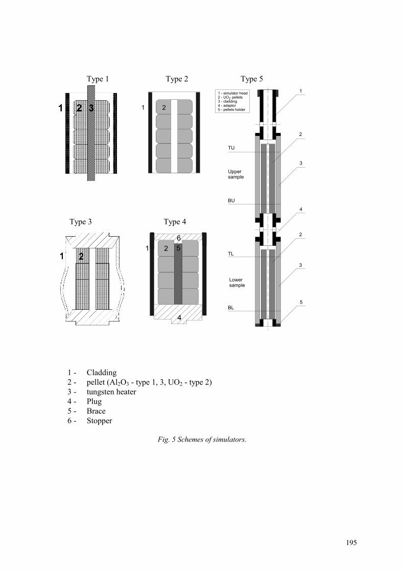
Type 1 Type 2 Type 5
Type 3 Type 4
1 - Cladding 2 - pellet (Al2O3 - type 1, 3, UO2 - type 2) 3 - tungsten heater 4 - Plug 5 - Brace 6 - Stopper
Fig. 5 Schemes of simulators.
1
2
3
4
2
3
5BL
TL
Lowersample
BU
TU
Uppersample
1 - simulator head2 - UO pellets3 - cladding4 - adaptor5 - pellets holder
2
195
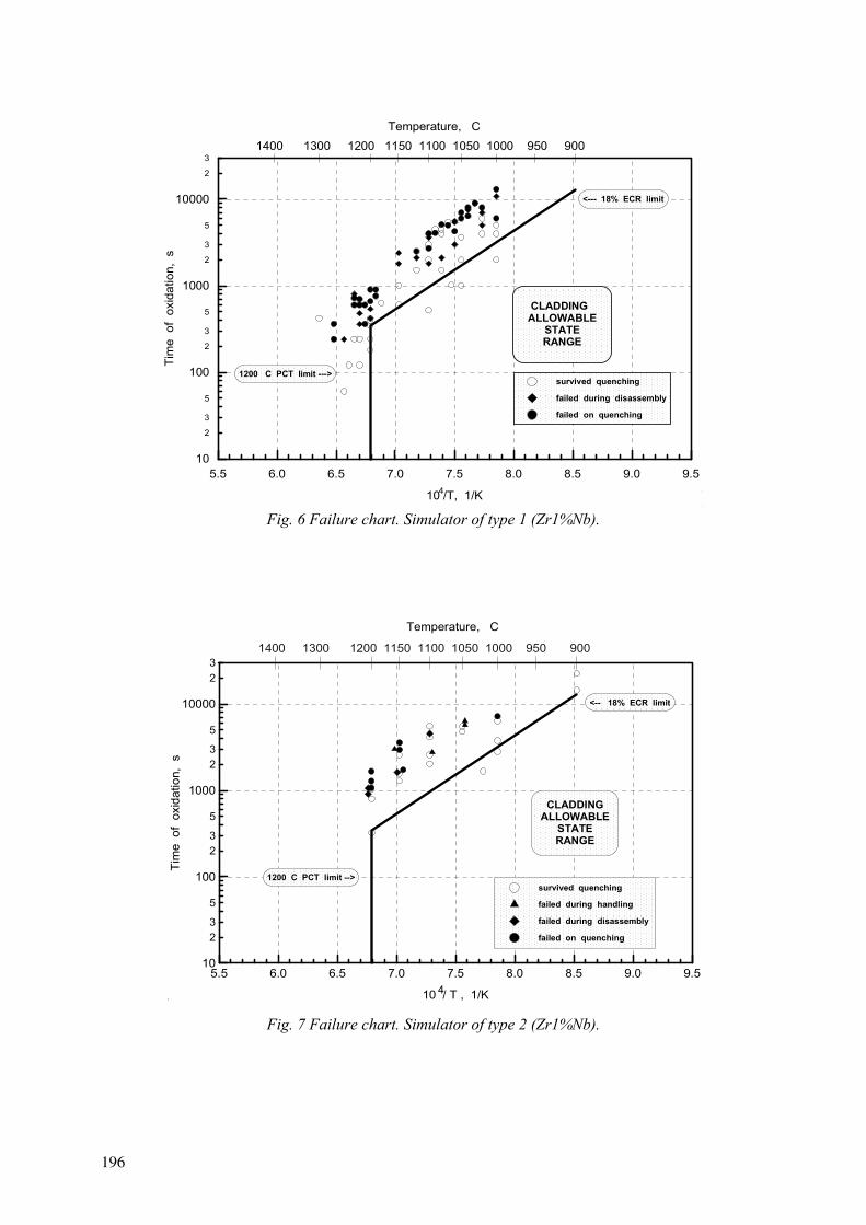
5.5 6.0 6.5 7.0 7.5 8.0 8.5 9.0 9.5
10 /T, 1/K
2
3
5
2
3
5
2
3
5
2
3
10
100
1000
10000
Tim
e o
f ox
idat
ion,
s
survived quenching
failed during disassembly
failed on quenching
1400 1300 1200 1150 1100 1050 1000 950 900Temperature, C
<--- 18% ECR limit
1200 PCT limit --->
4
CLADDING ALLOWABLE
STATERANGE
..
Fig. 6 Failure chart. Simulator of type 1 (Zr1%Nb).
5.5 6.0 6.5 7.0 7.5 8.0 8.5 9.0 9.5
10 / T , 1/K
23
5
23
5
23
5
23
10
100
1000
10000
Tim
e o
f ox
idat
ion,
s
4
Temperature, C
1400 1300 1200 1150 1100 1050 1000 950 900
.
CLADDINGALLOWABLE
STATERANGE
1200 PCT limit -->
<-- 18% ECR limit
survived quenching
failed during handling
failed during disassembly
failed on quenching
Fig. 7 Failure chart. Simulator of type 2 (Zr1%Nb).
196

5.5 6.0 6.5 7.0 7.5 8.0 8.5 9.0 9.5
10 / , 1/
23
5
23
5
23
5
23
10
100
1000
10000
Tim
e of
oxi
datio
n, s
4
Temperature, 1400 1300 1200 1150 1100 1050 1000 950 900
.
CLADDINGALLOWABLE
STATERANGE
18% ECR limit -->
1200 PCT limit-->
survived quenching
failed during handling
failed during disassembly
failed on quenching
Fig. 8 Failure chart. Simulator of type 3 (Zr1%Nb).
5.5 6.0 6.5 7.0 7.5 8.0 8.5 9.0 9.5
10 / , 1/
23
5
23
5
23
5
23
10
100
1000
10000
Tim
e o
f ox
idat
ion,
s
4
Temperature, Co
1400 1300 1200 1150 1100 1050 1000 950 900
.
CLADDINGALLOWABLE
ATATERANGE
1200 C limit -->o
<-- 18% ECR limit
survived quenching
failed on quenching
.
Fig. 9 Failure chart. Simulator of type 4 (Zr1%Nb).
197

burnup 49,5 MW d/kgU
a simulator 1 = 40 min b simulator 2 = 40 min c simulator 3 = 40 min
5.5 6.0 6.5 7.0 7.5 8.0 8.5 9.0 9.510 / T , 1/K
23
5
23
5
23
5
23
10
100
1000
10000
Tim
e o
f ox
idat
ion,
s
4
Temperature, C
1400 1300 1200 1150 1100 1050 1000 950 900
.
survived quenching
failed during disassembly
failed during withdrawal
CLADDINGALLOWABLE
STATERANGE
1200 PCT limit -->
<-- 18% ECR limit
.
Fig. 10 Post-test appearance and failure chart. Simulator of type 5 (Zr1%Nb).
198

5.5 6.0 6.5 7.0 7.5 8.0 8.5 9.0 9.5
10 /T, 1/K
23
5
23
5
23
5
23
10
100
1000
10000
Tim
e o
f ox
idat
ion,
s
1400 1300 1200 1150 1100 1050 1000 950 900
Temperature, Co
4
E635CLADDING
ALLOWABLESTATERANGE
<--- 18% ECR limit
1200 C limit --->o
survived quenching
failed during handling
failed during disassembly
failed on quenching
Zr1%Nb -->
.
Fig. 11 Failure chart. Simulator of type 2 (E635).
800 900 1000 1100 1200 1300
Temperature of oxidation, C
0
10
20
30
40
50
60
70
EC
R, %
o
non-deformed
deformed
up to 6 h
up to 1,9 h
up to 1,5 h
up to 0,7 h
up to 0,5 h
up to 0,3 h
<----
-
<----
----
<--
<----
------
<----
------
<---
up to 1,5 h
------>
up to 1,5 h
up to 0,3 h
------
>
--->
up to 0,3 h
<---
ZR1%NBCLADDINGALOWABLE
STATERANGE
Fig. 12 The fracture critical parameters. Simulators of type 1 – 5.
199
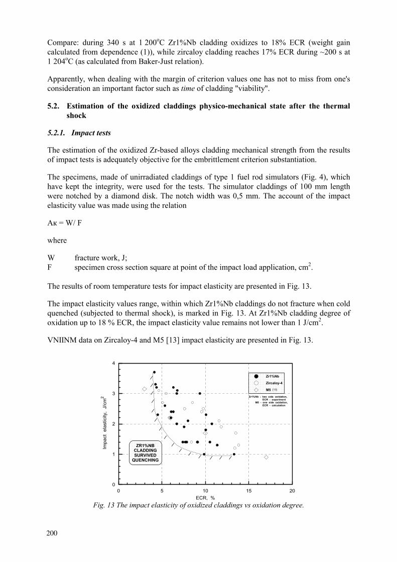
Compare: during 340 s at 1 200oC Zr1%Nb cladding oxidizes to 18% ECR (weight gain calculated from dependence (1)), while zircaloy cladding reaches 17% ECR during ~200 s at 1 204oC (as calculated from Baker-Just relation).
Apparently, when dealing with the margin of criterion values one has not to miss from one's consideration an important factor such as time of cladding "viability".
5.2. Estimation of the oxidized claddings physico-mechanical state after the thermal shock
5.2.1. Impact tests
The estimation of the oxidized Zr-based alloys cladding mechanical strength from the results of impact tests is adequately objective for the embrittlement criterion substantiation.
The specimens, made of unirradiated claddings of type 1 fuel rod simulators (Fig. 4), which have kept the integrity, were used for the tests. The simulator claddings of 100 mm length were notched by a diamond disk. The notch width was 0,5 mm. The account of the impact elasticity value was made using the relation
A = W/ F
where
W fracture work, J; F specimen cross section square at point of the impact load application, cm2.
The results of room temperature tests for impact elasticity are presented in Fig. 13.
The impact elasticity values range, within which Zr1%Nb claddings do not fracture when cold quenched (subjected to thermal shock), is marked in Fig. 13. At Zr1%Nb cladding degree of oxidation up to 18 % ECR, the impact elasticity value remains not lower than 1 J/cm2.
VNIINM data on Zircaloy-4 and 5 [13] impact elasticity are presented in Fig. 13.
0 5 10 15 20ECR, %
0
1
2
3
4
Impa
ct e
last
icity
, J/
cm2
////
/
/
//
//
/ / / / /
.
ZR1%NBCLADDINGSURVIVED
QUENCHING
Zr1%Nb - two side oxidation, ECR - experiment M5 - one side oxidation, ECR - calculation
Zr1%Nb
Zircaloy-4
M5 [13]
Fig. 13 The impact elasticity of oxidized claddings vs oxidation degree.
200
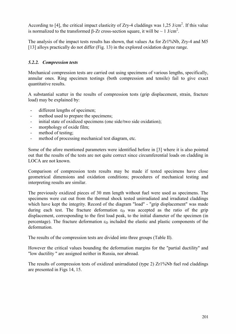
According to [4], the critical impact elasticity of Zry-4 claddings was 1,25 J/cm2. If this value is normalized to the transformed -Zr cross-section square, it will be ~ 1 J/cm2.
The analysis of the impact tests results has shown, that values A for Zr1%Nb, Zry-4 and M5 [13] alloys practically do not differ (Fig. 13) in the explored oxidation degree range.
5.2.2. Compression tests
Mechanical compression tests are carried out using specimens of various lengths, specifically, annular ones. Ring specimen testings (both compression and tensile) fail to give exact quantitative results.
A substantial scatter in the results of compression tests (grip displacement, strain, fracture load) may be explained by:
- different lengths of specimen; - method used to prepare the specimens; - initial state of oxidized specimens (one side/two side oxidation); - morphology of oxide film; - method of testing; - method of processing mechanical test diagram, etc.
Some of the afore mentioned parameters were identified before in [3] where it is also pointed out that the results of the tests are not quite correct since circumferential loads on cladding in LOCA are not known.
Comparison of compression tests results may be made if tested specimens have close geometrical dimensions and oxidation conditions; procedures of mechanical testing and interpreting results are similar.
The previously oxidized pieces of 30 mm length without fuel were used as specimens. The specimens were cut out from the thermal shock tested unirradiated and irradiated claddings which have kept the integrity. Record of the diagram "load" - "grip displacement" was made during each test. The fracture deformation D was accepted as the ratio of the grip displacement, corresponding to the first load peak, to the initial diameter of the specimen (in percentage). The fracture deformation D included the elastic and plastic components of the deformation.
The results of the compression tests are divided into three groups (Table II).
However the critical values bounding the deformation margins for the "partial ductility" and "low ductility " are assigned neither in Russia, nor abroad.
The results of compression tests of oxidized unirradiated (type 2) Zr1%Nb fuel rod claddings are presented in Figs 14, 15.
201
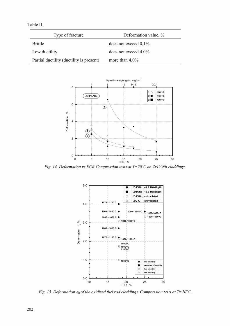
Table II.
Type of fracture Deformation value, %
Brittle does not exceed 0,1%
Low ductility does not exceed 4,0%
Partial ductility (ductility is present) more than 4,0%
0 5 10 15 20 25 30ECR, %
0
2
4
6
8
Def
orm
atio
n, %
1000
1100
1200 C
123
21
Zr1%Nb
Spesific weight gain, mg/cm
4 8 12 14,5 20,1
2
3
.
Fig. 14. Deformation vs ECR Compression tests at T=20oC on Zr1%Nb claddings.
10 15 20 25 30ECR, %
0.0
1.0
2.0
3.0
4.0
5.0
Def
orm
atio
n
, %
1000 - 1060
1000 - 1060
1070 - 1120
1000 - 1060
1000 - 1060
1070 - 1120
D
1000
1000 1000 1100
Zr1%Nb (49,5 MWd/kgU)
Zr1%Nb (49,5 MWd/kgU)
Zr1%Nb, unirradiated
Zry-4, unirradiated
1000-1060
1000-1060
1000-1060
1070-1120
low ductility
presence of ductility
low ductility
low ductility
Fig. 15. Deformation D of the oxidized fuel rod claddings. Compression tests at T=20oC.
202
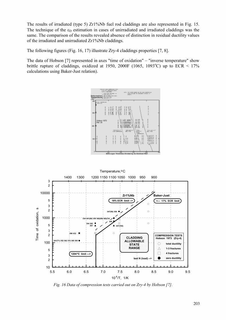
The results of irradiated (type 5) Zr1%Nb fuel rod claddings are also represented in Fig. 15. The technique of the D estimation in cases of unirradiated and irradiated claddings was the same. The comparison of the results revealed absence of distinction in residual ductility values of the irradiated and unirradiated Zr1%Nb claddings.
The following figures (Fig. 16, 17) illustrate Zry-4 claddings properties [7, 8].
The data of Hobson [7] represented in axes "time of oxidation" – "inverse temperature" show brittle rupture of claddings, oxidized at 1950, 2000F (1065, 1093 C) up to ECR < 17% calculations using Baker-Just relation).
5.5 6.0 6.5 7.0 7.5 8.0 8.5 9.0 9.5
10 /T, 1/K
23
5
23
5
23
5
23
10
100
1000
10000
Tim
e o
f ox
idat
ion,
s
1400 1300 1200 1150 1100 1050 1000 950 900
Temperature, Co
4
CLADDINGALLOWABLE
STATERANGE
<--- 17% ECR limit
1204 C limit --->o
Zr1%Nb
.
Baker-Just18% ECR limit -->
COMPRESSION TESTSHobson 1973 (Zry-4)
total ductility
1-3 fractures
4 fractures
zero ductilitytest N (load) -->
341(71) 352 362 372 385 393
398 432
354 383367
347(58) 358
334 341(80) 355 382(69) 382(74)340
347(100)
Fig. 16 Data of compression tests carried out on Zry-4 by Hobson [7].
203
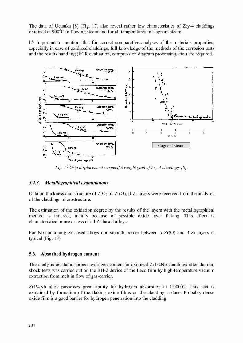
The data of Uetsuka [8] (Fig. 17) also reveal rather low characteristics of Zry-4 claddings oxidized at 900oC in flowing steam and for all temperatures in stagnant steam.
It's important to mention, that for correct comparative analyses of the materials properties, especially in case of oxidized claddings, full knowledge of the methods of the corrosion tests and the results handling (ECR evaluation, compression diagram processing, etc.) are required.
stagnant steam
Fig. 17 Grip displacement vs specific weight gain of Zry-4 claddings [8].
5.2.3. Metallographical examinations
Data on thickness and structure of ZrO2, -Zr(O), -Zr layers were received from the analyses of the claddings microstructure.
The estimation of the oxidation degree by the results of the layers with the metallographical method is inderect, mainly because of possible oxide layer flaking. This effect is characteristical more or less of all Zr-based alloys.
For Nb-containing Zr-based alloys non-smooth border between -Zr(O) and -Zr layers is typical (Fig. 18).
5.3. Absorbed hydrogen content
The analysis on the absorbed hydrogen content in oxidized Zr1%Nb claddings after thermal shock tests was carried out on the RH-2 device of the Leco firm by high-temperature vacuum extraction from melt in flow of gas-carrier.
Zr1%Nb alloy possesses great ability for hydrogen absorption at 1 000 . This fact is explained by formation of the flaking oxide films on the cladding surface. Probably dense oxide film is a good barrier for hydrogen penetration into the cladding.
ECR, %.0 1 2 3 4 5
204
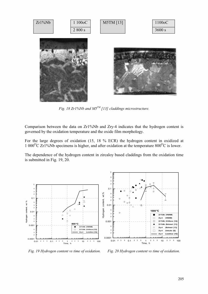
Zr1%Nb 1 100oC M5TM [13] 1100oC
2 800 s 3600 s
Fig. 18 Zr1%Nb and 5TM [13] claddings microstructure.
Comparison between the data on Zr1%Nb and Zry-4 indicates that the hydrogen content is governed by the oxidation temperature and the oxide film morphology.
For the large degrees of oxidation (15, 18 % ECR) the hydrogen content in oxidized at 1 000 Zr1%Nb specimens is higher, and after oxidation at the temperature 800 is lower.
The dependence of the hydrogen content in zircaloy based claddings from the oxidation time is submitted in Fig. 19, 20.
2 3 5 2 3 5 2 3 5 2 3 50.01 0.1 1 10 100Time, h
2
3
5
2
3
5
2
3
5
2
3
5
0.0001
0.001
0.01
0.1
1
Hyd
roge
n c
onte
nt,
wt.
%
Zr1%Nb (VNIINM)
Zr1%Nb (Vrtilkova [12])
Zry-4 (Leistikov [10])
o
.
.
800 C
2 3 5 2 3 5 2 3 5 2 3 50.01 0.1 1 10 100Time, h
2
3
5
2
3
5
2
3
5
2
3
5
0.0001
0.001
0.01
0.1
1
Hyd
roge
n c
onte
nt,
wt.%
Zr1%Nb (VNIINM)
Zry-4 (VNIINM)
Zr1%Nb (Vrtilkova [12])
Zr1%Nb (Bohmert [11])
Zry-4 (Bohmert [11])
Zry-4 (Uetsuka [9])
Zry-4 (Leistikow [10])
o
.
.
1000 C
Fig. 19 Hydrogen content vs time of oxidation. Fig. 20 Hydrogen content vs time of oxidation.
205

The results of testings for thermal shock and compression of unirradiated and irradiated oxidized claddings demonstrate their similar behaviour and properties as well as the availability of a margin in the embrittlement criterion parameters. This is likely to be explained by the comparable content of hydrogen in unirradiated and irradiated oxidized Zr1%Nb claddings. It is known that the initial hydrogen quantity in irradiated Zr1%Nb claddings is low (30 – 80 ppm) [14].
However, the initial content of hydrogen in irradiated Zry claddings is higher, up to 800 ppm [15]. The low ductility properties of Zry claddings of high hydrogen content are evidenced by the data of [8] (Fig. 21) and [16] (Fig. 22).
Fig. 21 Grip displacement and Zry-4 claddings weight gain vs hydrogen content. Compression tests at Tcompression=100 C [8].
Aside from this, the procedure used to determine the hydrogen content of high oxidized claddings needs an accurate interpretation. To a significant extent this refers to claddings oxidized at 1 000oC. This temperature gives rise to flaking oxide films formation on the Zr1%Nb claddings. The quantity of ZrO2 that remains on a sample used to determine hydrogen content is different. This may be one of the reasons for the incorrect determined hydrogen content in high oxidized samples.
Zr1%Nb Zry-4
Fig. 22 Relative deformation (Zr1%Nb and Zry-4 [16] claddings oxidized at 900oC) vs ECR. Compression tests at Tcompression=20 C.
206

6. CONCLUSIONS
Behaviour and properties of Zr1%Nb claddings for WWER type fuels were investigated under loading conditions simulating core flooding with water in LOCA.
The experimental data base is sufficient to judge the character and numerical value of criterial parameters of the embrittlement criterion in terms of the cladding ability to withstand thermal-force loading upon quenching and to keep the mechanical strength after LOCA sufficient for subsequent manipulations with the FA (unloading, transport).
The representative embrittlement criterion comprises altogether the maximal temperature to which the cladding may be heated (PCT) and the local depth of the cladding oxidation (ECR).
The numerical values "1 200 - 18 % ECR" for Zr1%Nb claddings nave been justified by the data experimentally obtained from studies into the kinetics of the Zr-steam reaction and by thermal resistance tests data.
The results of thermal shock tests with unirradiated and irradiated claddings (burnup of 50 MW d/kgU) corroborate directly the fulfilment of the embrittlement criterion by Zr1%Nb claddings at the flooding stage in LOCA.
The partial ductility the availability of which is confirmed by the mechanical tests ensures the fulfilment of the embrittlement criterion after LOCA, viz., upon FA unloading and transport.
The fulfilment of the embrittlement criterion for unirradiated, non-deformed E635 alloy claddings is shown.
REFERENCES
[1] Nuclear safety rules for NPP reactor facilities. Effective since 01.09.90. [2] YU.K. BIBILASHVILY, N.B. SOKOLOV, L.N. ANDREYEVA-ANDRIEVSKAYA, A.V.
SALATOV, A.M. MOROZOV High-temperature Interaction of Fuel Rod Cladding Material (Zr1%Nb alloy) with Oxygen-containing Media. Proceedings of IAEA Technical Committee on Behaviour of LWR Core Materials under Accident Conditions, held in Dimitrovgrad, Russia, 9-13 October 1995. IAEA-TECDOC-921, Vienna, 996, pp.117-128.
[3] WILLIFORD R.E. Safety margins in zircaloy oxidation and embrittlement criteria for emergency core cooling system acceptance.// Nuclear Technology, 1986, v. 74, pp. 333-346.
[4] CHANG H.M., GARDE A.M., KASSNER T.F. Development of oxygen embrittlement criterion for zircaloy cladding applicable to loss-of-coolant accident conditions in light-water reactors. In: Zirconium in the Nuclear Industry (Fourth Conference), ASTM STP 681, ASTM, 1979, pp. 600-627.
[5] YU.K. BIBILASHVILY, N.B. SOKOLOV, A.V. SALATOV, L.N. ANDREYEVA-ANDRIEVSKAYA, O.A. NECHAEVA, F.Yu. VLASOV. RAPTA-5 Code: Modelling of Behaviour of Fuel Elements of VVER Type in Design Accidents. Verification Calculations. Proceedings of IAEA Technical Committee on Behaviour of LWR Core Materials under Accident Conditions, held in Dimitrovgrad, Russia, on 9-13 October 1995. IAEA-TECDOC-921, Vienna, 1996, pp. 139-152.
207
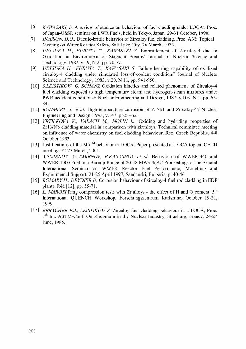
[6] KAWASAKI, S. A review of studies on behaviour of fuel cladding under LOCAs. Proc. of Japan-USSR seminar on LWR Fuels, held in Tokyo, Japan, 29-31 October, 1990.
[7] HOBSON, D.O., Ductile-brittle behavior of Zircaloy fuel cladding, Proc. ANS Topical Meeting on Water Reactor Safety, Salt Lake City, 26 March, 1973.
[8] UETSUKA H., FURUTA T., KAWASAKI S. Embrittlement of Zircaloy-4 due to Oxidation in Environment of Stagnant Steam// Journal of Nuclear Science and Technology, 1982, v.19, N 2, pp. 70-77.
[9] UETSUKA H., FURUTA T., KAWASAKI S. Failure-bearing capability of oxidized zircaloy-4 cladding under simulated loss-of-coolant condition// Journal of Nuclear Science and Technology , 1983, v.20, N 11, pp. 941-950.
[10] S.LEISTIKOW, G. SCHANZ Oxidation kinetics and related phenomena of Zircaloy-4 fuel cladding exposed to high temperature steam and hydrogen-steam mixtures under PWR accident conditions// Nuclear Engineering and Design, 1987, v.103, N 1, pp. 65-84.
[11] BOHMERT, J. et al. High-temperature corrosion of ZrNb1 and Zircaloy-4// Nuclear Engineering and Design, 1993, v.147, pp.53-62.
[12] VRTILKOVA V., VALACH M., MOLIN L.. Oxiding and hydriding properties of Zr1%Nb cladding material in comparison with zircaloys. Technical committee meeting on influence of water chemistry on fuel cladding behaviour. Rez, Czech Republic, 4-8 October 1993.
[13] Justifications of the M5TM behavior in LOCA. Paper presented at LOCA topical OECD meeting. 22-23 March, 2001.
[14] A.SMIRNOV, V. SMIRNOV, B.KANASHOV et al. Behaviour of WWER-440 and WWER-1000 Fuel in a Burnup Range of 20-48 MW d/kgU/ Proceedings of the Second International Seminar on WWER Reactor Fuel Performance, Modelling and Experimental Support, 21-25 April 1997, Sandanski, Bulgaria, p. 40-46.
[15] ROMARY H., DEYDIER D. Corrosion behaviour of zircaloy-4 fuel rod cladding in EDF plants. Ibid [12], pp. 55-71.
[16] L. MAROTI Ring compression tests with Zr alloys - the effect of H and O content. 5th
International QUENCH Workshop, Forschungszentrum Karlsruhe, October 19-21, 1999.
[17] ERBACHER F.J., LEISTIKOW S. Zircaloy fuel cladding behaviour in a LOCA, Proc. 7th Int. ASTM-Conf. On Zirconium in the Nuclear Industry, Strasburg, France, 24-27 June, 1985.
208
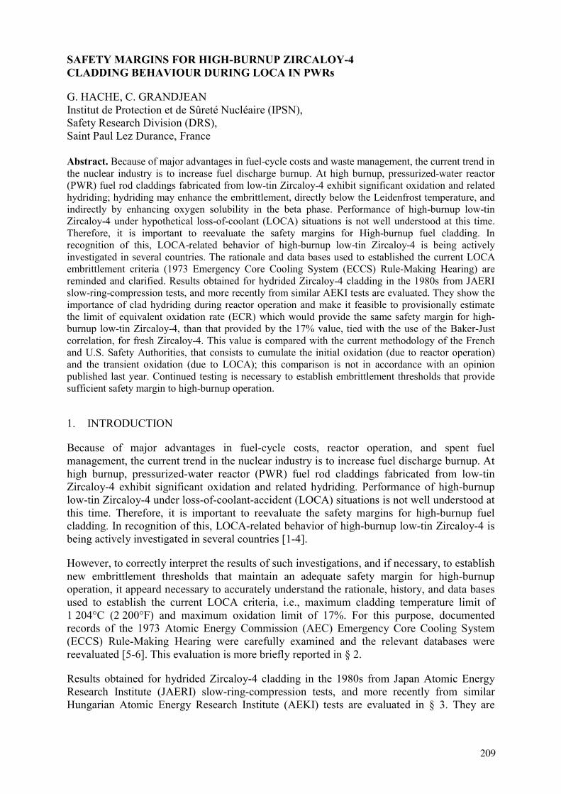
SAFETY MARGINS FOR HIGH-BURNUP ZIRCALOY-4CLADDING BEHAVIOUR DURING LOCA IN PWRs
G. HACHE, C. GRANDJEAN Institut de Protection et de Sûreté Nucléaire (IPSN), Safety Research Division (DRS), Saint Paul Lez Durance, France
Abstract. Because of major advantages in fuel-cycle costs and waste management, the current trend in the nuclear industry is to increase fuel discharge burnup. At high burnup, pressurized-water reactor (PWR) fuel rod claddings fabricated from low-tin Zircaloy-4 exhibit significant oxidation and related hydriding; hydriding may enhance the embrittlement, directly below the Leidenfrost temperature, and indirectly by enhancing oxygen solubility in the beta phase. Performance of high-burnup low-tin Zircaloy-4 under hypothetical loss-of-coolant (LOCA) situations is not well understood at this time. Therefore, it is important to reevaluate the safety margins for High-burnup fuel cladding. In recognition of this, LOCA-related behavior of high-burnup low-tin Zircaloy-4 is being actively investigated in several countries. The rationale and data bases used to established the current LOCA embrittlement criteria (1973 Emergency Core Cooling System (ECCS) Rule-Making Hearing) are reminded and clarified. Results obtained for hydrided Zircaloy-4 cladding in the 1980s from JAERI slow-ring-compression tests, and more recently from similar AEKI tests are evaluated. They show the importance of clad hydriding during reactor operation and make it feasible to provisionally estimate the limit of equivalent oxidation rate (ECR) which would provide the same safety margin for high-burnup low-tin Zircaloy-4, than that provided by the 17% value, tied with the use of the Baker-Just correlation, for fresh Zircaloy-4. This value is compared with the current methodology of the French and U.S. Safety Authorities, that consists to cumulate the initial oxidation (due to reactor operation) and the transient oxidation (due to LOCA); this comparison is not in accordance with an opinion published last year. Continued testing is necessary to establish embrittlement thresholds that provide sufficient safety margin to high-burnup operation.
1. INTRODUCTION
Because of major advantages in fuel-cycle costs, reactor operation, and spent fuel management, the current trend in the nuclear industry is to increase fuel discharge burnup. At high burnup, pressurized-water reactor (PWR) fuel rod claddings fabricated from low-tin Zircaloy-4 exhibit significant oxidation and related hydriding. Performance of high-burnup low-tin Zircaloy-4 under loss-of-coolant-accident (LOCA) situations is not well understood at this time. Therefore, it is important to reevaluate the safety margins for high-burnup fuel cladding. In recognition of this, LOCA-related behavior of high-burnup low-tin Zircaloy-4 is being actively investigated in several countries [1-4].
However, to correctly interpret the results of such investigations, and if necessary, to establish new embrittlement thresholds that maintain an adequate safety margin for high-burnup operation, it appeard necessary to accurately understand the rationale, history, and data bases used to establish the current LOCA criteria, i.e., maximum cladding temperature limit of 1 204°C (2 200°F) and maximum oxidation limit of 17%. For this purpose, documented records of the 1973 Atomic Energy Commission (AEC) Emergency Core Cooling System (ECCS) Rule-Making Hearing were carefully examined and the relevant databases were reevaluated [5-6]. This evaluation is more briefly reported in § 2.
Results obtained for hydrided Zircaloy-4 cladding in the 1980s from Japan Atomic Energy Research Institute (JAERI) slow-ring-compression tests, and more recently from similar Hungarian Atomic Energy Research Institute (AEKI) tests are evaluated in § 3. They are
209

extrapolated in § 4 to provisionally estimate the limit of equivalent oxidation rate (ECR) which would provide the same safety margin for high-burnup low-tin Zircaloy-4, than that provided by the current ECR criterion for fresh Zircaloy-4, and compared with current methodologies and a last year publication.
2. RATIONALE OF CURRENT LOCA CRITERIA
2.1. Primary Objectives of Current Criteria for fresh zircaloys
In 1967, an Advisory Task Force on Power Reactor Emergency Cooling [7], appointed to provide "additional assurance that substantial meltdown is prevented" by core cooling systems, concluded that:
"The analysis of (a LOCA) requires that the core be maintained in place and essentially intact to preserve the heat-transfer area and coolant-flow geometry. Without preservation of heat-transfer area and coolant-flow geometry, fuel-element melting and core disassembly would be expected… Continuity of emergency core cooling must be maintained after termination of the temperature transient for an indefinite period until the heat generation decays to an insignificant level, or until disposition of the core is made."
This rationale makes it plainly clear that it is most important to preserve the heat transfer area and the coolant flow geometry not only during the short-term portion of the core temperature transient but also for long term.
Consistent with the conclusions of the Ergen Task Force, the U.S. Atomic Energy Commission (AEC) promulgated Criterion 35 of the General Design Criteria [8] which states that: "... fuel and clad damage that could interfere with continued effective core cooling is prevented."
At the end of the Emergency Core Cooling System (ECCS) Rule-Making Hearing in 1973, the AEC Commissioners wrote:
"In view of the fundamental and historical importance of maintaining core coolability, we retain this criterion as a basic objective, in a more general form than it appeared in the Interim Acceptance Criteria. It is not controversial as a criterion… Although most of the attention of the ECCS hearings has been focused on the events of the first few minutes after a postulated major cooling line break, up to the time that the cladding would be cooled to a temperature of 300°F or less, the long-term maintenance of cooling would be equally important [9]."
2.2. Metallurgy of Cladding Embrittlement
The oxygen embrittlement effect during steam reactions with Zircaloy-clad fuel rods at high temperatures is well known. Ductility of cladding could be severely degraded if the degree of oxidation is high. If the embrittled cladding fragments into small pieces, the coolability of the core could be seriously impaired.
Significantly oxidized cladding can fragment during the quenching phase of a LOCA. The action of rewetting by ECCS water involves the collapse of the vapor film that covers the cladding outer-diameter (OD) surface prior to subsequent transition to nucleate boiling. This event takes place at a more or less constant temperature, i.e., the Leidenfrost temperature. For
210

oxidized Zircaloy-4 cladding rewetted by bottom-flooding water, ANL investigators reported that rewetting occurs in the range of 475-600°C [10]. The abrupt change in the heat transfer conditions induces large thermal-shock stress, which can fracture the cladding, if it is sufficiently embrittled by oxidation.
Below the Leidenfrost temperature, there is continued risk of fragmentation after quenching. In accordance with the opinions of the Ergen Task Force and the AEC commissioners mentioned earlier, other experts also wrote a similar opinion for OECD Committee on Safety of Nuclear Installations (CSNI) [11]: "The ability of the cladding to withstand the thermal-shock stresses of quenching during rewetting or post-LOCA forces is related to the extent and detailed nature of oxidation during the transient. The post-LOCA forces, which need to be taken into account, are the hydraulic, seismic, handling, and transport forces."
Besides the oxygen effect on the susceptibility of oxidized cladding to quench embrittlement, there is a synergetic effect of hydrogen. Hydrogen uptake may occur during irradiation (e.g., in high-burnup Zircaloy-4) or during transient oxidation in steam (e.g., from cladding inner surface in contact with stagnant steam near a ballooned and burst region). For cooling rates typical of bottom flooding of core, most hydrogen atoms remain in solution in the beta phase at Leidenfrost temperature, and in such state, hydrogen has little effect on the fracture resistance of an oxidized Zircaloy. However, when load is imposed at temperatures below the Leidenfrost temperature, precipitated hydrides strongly influence the fracture resistance of cladding. Eutectoid decomposition of hydrogen-stabilized beta phase at temperatures below
550°C [12] is the major factor that causes this deleterious effect (see Fig. 1.).
Fig.1. Zr-H binary phase diagram (from E. Zuzek et al., Bulletin of Alloy Phase Diagrams, Vol. 11, No. 4, 1990, pp. 385-395).
2.3. Opinion of Regulatory Staff and Commissioners during 1973 Rule-Making Hearing
2.3.1. Reluctance to Neglect Effects of Mechanical Constraints
Some factors during a LOCA, such as ballooning of the rod near the spacer grid, rod bowing, rod-grid spring chemical interaction, and the friction between the fuel rod and spacer grids, can restrict the axial movement of the cladding. Also, guide tubes in a PWR fuel assembly are mechanically fixed to the spacer grids. Because of these factors, fuel rods during reflooding will be subject to tensile load that is produced due to the differential axial shrinkage between a cladding and the guide tube. Rods may interact each other due to ballooning or bowing and will be subject to radial load. For high-burnup fuels in which tight pellet-cladding bonding is common, axial shrinkage can be restricted if the tight bonding remains unchanged after
211

ballooning and burst. These constraints will remain after quench, when deleterious effects of oxygen and hydrogen are far more pronounced.
In recognition of this, the AEC Regulatory Staff wrote during the 1973 Rule-Making Hearing that "the loads due to assembly restraint and rod-to-rod interaction may not be small compared to the thermal shock load and cannot be neglected [13]." Subsequently, it was concluded that: "The staff believes that quench loads are likely the major loads, but the staff does not believe that the evidence is as yet conclusive enough to ignore all other loads[14]."
Then, the Commissioners added: "There is some lack of certainty as to just what nature of stresses would be encountered during the LOCA.... (We want) to draw attention to the fact that it may not be possible to anticipate and calculate all of the stresses to which fuel rods would be subjected in a LOCA. Although we believe the calculations of thermal shock stresses are worthwhile and informative, we agree with the regulatory staff that they are not sufficiently well defined to depend on for regulatory purposes [9]."
2.3.2. Preservation of Ductility and Consideration of Results from Unconstrained Quench Test
At the end of the 1973 Hearing, the AEC Commissioners wrote:
"...Nevertheless we find the quench results encouraging in that they provide assurance that the 2200°F limit is conservative. Our selection of the 2200°F limit results primarily from our belief that retention of ductility in the Zircaloy is the best guarantee of its remaining intact during the hypothetical LOCA... The thermal shock tests are reassuring, but their use for licensing purposes would involve an assumption of knowledge of the detailed process taking place in the core during a LOCA that we do not believe is justified [9]."
Without much ambiguity, this conclusion clearly expressed the belief that retention of ductility was considered the best guarantee against potential fragmentation under various types of loading (thermal-shock, bundle constraints, hydraulic, handling, and seismic forces). During the 1973 Hearing, results from unconstrained quench tests (simple thermal-shock test) were considered only corroborative and reassuring. However, their use for regulatory purposes was not accepted.
0
10
20
30
40
50
60
70
80
90
100
900 1100 1300 1500 1700 1900
Eq
uiv
alen
t C
lad
din
g R
eact
ed (
%)
Oxidation Temperature (°C)
Nonirradiated Zircaloys
Direct Quenching afterOxidation at High Temperature
INTACTFAIL
17% limit
Chung & Kassner
Hesson
Scatena
Grandjean & Lebuffe1204°C limit
Fig. 2. Failure boundary of partially constrained Zircaloy cladding tubes or unconstrained rings after oxidation at high temperature and direct quenching from peak oxidation temperature (from Refs. 10 and 1 ).
212
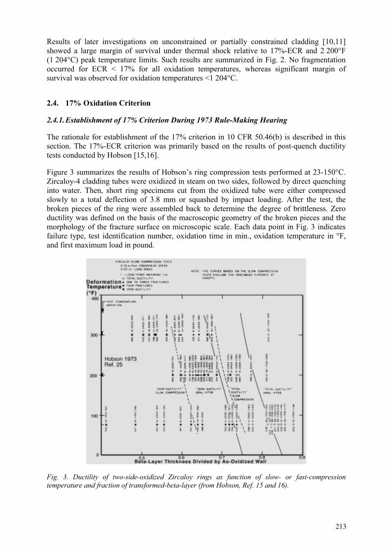
Results of later investigations on unconstrained or partially constrained cladding [10,11] showed a large margin of survival under thermal shock relative to 17%-ECR and 2 200°F (1 204°C) peak temperature limits. Such results are summarized in Fig. 2. No fragmentation occurred for ECR < 17% for all oxidation temperatures, whereas significant margin of survival was observed for oxidation temperatures <1 204°C.
2.4. 17% Oxidation Criterion
2.4.1. Establishment of 17% Criterion During 1973 Rule-Making Hearing
The rationale for establishment of the 17% criterion in 10 CFR 50.46(b) is described in this section. The 17%-ECR criterion was primarily based on the results of post-quench ductility tests conducted by Hobson [15,16].
Figure 3 summarizes the results of Hobson’s ring compression tests performed at 23-150°C. Zircaloy-4 cladding tubes were oxidized in steam on two sides, followed by direct quenching into water. Then, short ring specimens cut from the oxidized tube were either compressed slowly to a total deflection of 3.8 mm or squashed by impact loading. After the test, the broken pieces of the ring were assembled back to determine the degree of brittleness. Zero ductility was defined on the basis of the macroscopic geometry of the broken pieces and the morphology of the fracture surface on microscopic scale. Each data point in Fig. 3 indicates failure type, test identification number, oxidation time in min., oxidation temperature in °F, and first maximum load in pound.
Fig. 3. Ductility of two-side-oxidized Zircaloy rings as function of slow- or fast-compression temperature and fraction of transformed-beta-layer (from Hobson, Ref. 15 and 16).
213
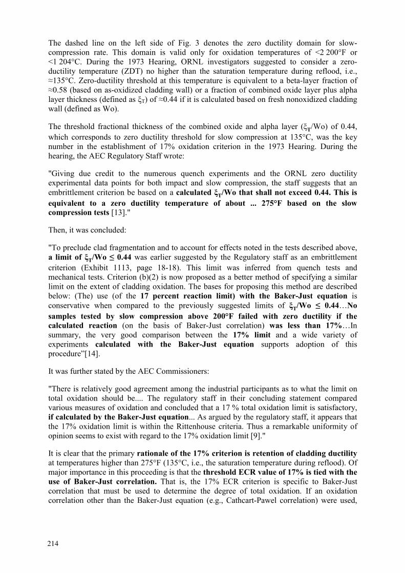
The dashed line on the left side of Fig. 3 denotes the zero ductility domain for slow-compression rate. This domain is valid only for oxidation temperatures of <2 200°F or <1 204°C. During the 1973 Hearing, ORNL investigators suggested to consider a zero-ductility temperature (ZDT) no higher than the saturation temperature during reflood, i.e.,
135°C. Zero-ductility threshold at this temperature is equivalent to a beta-layer fraction of 0.58 (based on as-oxidized cladding wall) or a fraction of combined oxide layer plus alpha
layer thickness (defined as T) of 0.44 if it is calculated based on fresh nonoxidized cladding wall (defined as Wo).
The threshold fractional thickness of the combined oxide and alpha layer ( T/Wo) of 0.44, which corresponds to zero ductility threshold for slow compression at 135°C, was the key number in the establishment of 17% oxidation criterion in the 1973 Hearing. During the hearing, the AEC Regulatory Staff wrote:
"Giving due credit to the numerous quench experiments and the ORNL zero ductility experimental data points for both impact and slow compression, the staff suggests that an embrittlement criterion be based on a calculated T/Wo that shall not exceed 0.44. This is equivalent to a zero ductility temperature of about ... 275°F based on the slow compression tests [13]."
Then, it was concluded:
"To preclude clad fragmentation and to account for effects noted in the tests described above, a limit of T/Wo 0.44 was earlier suggested by the Regulatory staff as an embrittlement criterion (Exhibit 1113, page 18-18). This limit was inferred from quench tests and mechanical tests. Criterion (b)(2) is now proposed as a better method of specifying a similar limit on the extent of cladding oxidation. The bases for proposing this method are described below: (The) use (of the 17 percent reaction limit) with the Baker-Just equation is conservative when compared to the previously suggested limits of T/Wo 0.44…Nosamples tested by slow compression above 200°F failed with zero ductility if the calculated reaction (on the basis of Baker-Just correlation) was less than 17%…In summary, the very good comparison between the 17% limit and a wide variety of experiments calculated with the Baker-Just equation supports adoption of this procedure”[14].
It was further stated by the AEC Commissioners:
"There is relatively good agreement among the industrial participants as to what the limit on total oxidation should be.... The regulatory staff in their concluding statement compared various measures of oxidation and concluded that a 17 % total oxidation limit is satisfactory, if calculated by the Baker-Just equation... As argued by the regulatory staff, it appears that the 17% oxidation limit is within the Rittenhouse criteria. Thus a remarkable uniformity of opinion seems to exist with regard to the 17% oxidation limit [9]."
It is clear that the primary rationale of the 17% criterion is retention of cladding ductilityat temperatures higher than 275°F (135°C, i.e., the saturation temperature during reflood). Of major importance in this proceeding is that the threshold ECR value of 17% is tied with the use of Baker-Just correlation. That is, the 17% ECR criterion is specific to Baker-Just correlation that must be used to determine the degree of total oxidation. If an oxidation correlation other than the Baker-Just equation (e.g., Cathcart-Pawel correlation) were used,
214

the threshold ECR would have been less than 17%. This means that use of a best-estimate correlation may not necessarily be conservative in evaluating post-quench cladding ductility.
2.4.2. 17% Oxidation Limit and Resistance to Impact Failure at Large Hydrogen Uptake
After the 1973 Hearing, ANL investigators performed 0.15- and 0.3-J pendulum impact tests at 23°C on pressurized Zircaloy-4 tubes that were burst, oxidized, cooled at 5°C/s, and survived quenching thermal shock [10]. The CSNI experts [11] considered that: "Ambient impact of 0.3 J were thought to be a reasonable approximation to post LOCA quench ambient impact loads." The results of the 0.3-J impact tests, summarized in Fig. 4, indicate that the 17%-ECR limit is adequate to prevent a burst-and-oxidized cladding from failure under 0.3-J impact at 23°C, as long as peak cladding temperature remained 1 204°C. The ECR values in the figure were determined based on measured thickness of oxide, alpha, and beta phase layers, rather than calculated based on Baker-Just correlation, and hence, are considered more accurate.
0
10
20
30
40
50
60
70
900 1000 1100 1200 1300 1400 1500
failed
intact
Eq
uiv
alen
t C
lad
din
g R
eact
ed (
%)
Isothermal Oxidation Temperature (°C)
Zircaloy-4 tube filled withalumina pellets,OD 10.9 mm, WT 0.635 mm,burst and oxidized in steam
Impact testat 23°C
H 20-2200 wppmafter quench
Chung & Kassner 1980NUREG/CR-1344
Fig. 4. Impact failure threshold as function of equivalent cladding reacted and oxidation temperature of burst, oxidized, slow-cooled, and quenched Zircaloy-4 tube containing 20-2 200 wppm hydrogen (from Ref. 10).
In contrast to Hobson’s two-side-oxidized non-pressurized non-ruptured tubes in which hydrogen uptake was small, burst Zircaloy-4 tubes exhibited peculiar oxidation behavior near the burst opening. The inner-diameter (ID) surfaces of the top and bottom "necks," 30-mm away from the burst center, were exposed to hydrogen-rich stagnant steam-hydrogen mixture which is produced because of poor mixing of steam and hydrogen at the narrow gap between the alumina pellets and the ID surface of the necks. As a consequence, thick breakaway oxides formed at 900-1 120°C [10], and hydrogen uptake as high as 2 200 wppm was observed at the "necked" regions.
215

2.4.3. 17% Oxidation Limit and Survival under Constraint Thermal Shock
Before 1973, no thermal-shock quench test was performed on mechanically constrained cladding specimens. Then in early 1980s, Uetsuka et al. performed quenching tests on cladding sections under severely constrained condition [17]. In their experiment, cladding tube was fixed at the bottom but was allowed to freely elongate in axial direction during oxidation at high temperature. As a result, cladding length increased freely because of thermal expansion and oxide-induced creep. At the end of the isothermal oxidation, the specimen top was fixed to the crosshead of an Instron tensile facility. Thus, at Leidenfrost temperature, the cladding tube was subjected to combined axial-tensile and thermal-shock stresses. The results of the tests are summarized in the Fig. 5.
Fig. 5. Failure-nonfailure boundary for fully constrained Zircaloy-4 after oxidation in steam and quenching as function of oxidation time and temperature; total oxidation calculated with Baker-Just equation is also indicated (from Uetsuka et al., J. Nucl. Sci. Tech. 20, 1983, pp. 941-950).
The 17% oxidation limit, calculated with Baker-Just correlation, appears to be adequate for protection of constrained rods against thermal-shock failure (Fig. 5). JAERI investigators confirmed occurrence of high hydrogen uptake in the “necked” regions near the burst opening.
2.4.4. 17% Oxidation Criterion - Summary
It is clear that the primary rationale of the 17% ECR criterion is retention of cladding ductility at temperatures higher than 275°F (135°C), i.e., the saturation temperature during reflood. The threshold ECR value of 17% is tied with the use of Baker-Just correlation. If a best-estimate correlation other than Baker-Just equation (e.g., Cathcart-Pawel correlation) were used, the threshold ECR would have been <17%.
Investigations conducted after the 1973 Rule-Making Hearing showed that for oxidation temperatures 1 204°C, the 17% oxidation limit (as calculated with Baker-Just correlation) is
216
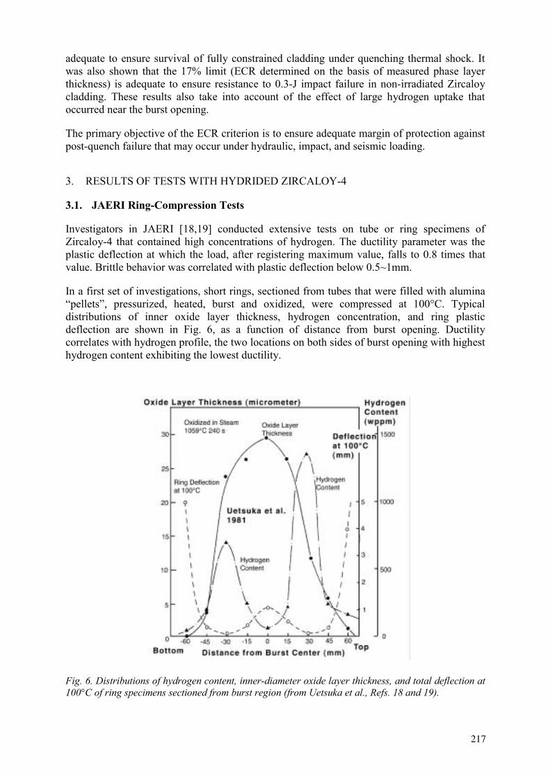
adequate to ensure survival of fully constrained cladding under quenching thermal shock. It was also shown that the 17% limit (ECR determined on the basis of measured phase layer thickness) is adequate to ensure resistance to 0.3-J impact failure in non-irradiated Zircaloy cladding. These results also take into account of the effect of large hydrogen uptake that occurred near the burst opening.
The primary objective of the ECR criterion is to ensure adequate margin of protection against post-quench failure that may occur under hydraulic, impact, and seismic loading.
3. RESULTS OF TESTS WITH HYDRIDED ZIRCALOY-4
3.1. JAERI Ring-Compression Tests
Investigators in JAERI [18,19] conducted extensive tests on tube or ring specimens of Zircaloy-4 that contained high concentrations of hydrogen. The ductility parameter was the plastic deflection at which the load, after registering maximum value, falls to 0.8 times that value. Brittle behavior was correlated with plastic deflection below 0.5~1mm.
In a first set of investigations, short rings, sectioned from tubes that were filled with alumina “pellets”, pressurized, heated, burst and oxidized, were compressed at 100°C. Typical distributions of inner oxide layer thickness, hydrogen concentration, and ring plastic deflection are shown in Fig. 6, as a function of distance from burst opening. Ductility correlates with hydrogen profile, the two locations on both sides of burst opening with highest hydrogen content exhibiting the lowest ductility.
Fig. 6. Distributions of hydrogen content, inner-diameter oxide layer thickness, and total deflection at 100°C of ring specimens sectioned from burst region (from Uetsuka et al., Refs. 18 and 19).
217
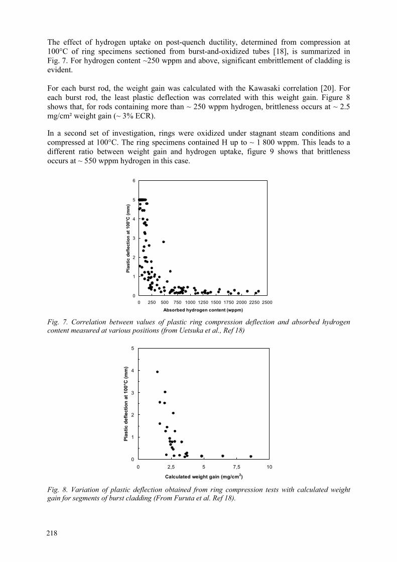
The effect of hydrogen uptake on post-quench ductility, determined from compression at 100°C of ring specimens sectioned from burst-and-oxidized tubes [18], is summarized in Fig. 7. For hydrogen content ~250 wppm and above, significant embrittlement of cladding is evident.
For each burst rod, the weight gain was calculated with the Kawasaki correlation [20]. For each burst rod, the least plastic deflection was correlated with this weight gain. Figure 8 shows that, for rods containing more than ~ 250 wppm hydrogen, brittleness occurs at ~ 2.5 mg/cm² weight gain (~ 3% ECR).
In a second set of investigation, rings were oxidized under stagnant steam conditions and compressed at 100°C. The ring specimens contained H up to ~ 1 800 wppm. This leads to a different ratio between weight gain and hydrogen uptake, figure 9 shows that brittleness occurs at ~ 550 wppm hydrogen in this case.
0
1
2
3
4
5
6
0 250 500 750 1000 1250 1500 1750 2000 2250 2500Absorbed hydrogen content (wppm)
Plas
tic d
efle
ctio
n at
100
°C (m
m)
Fig. 7. Correlation between values of plastic ring compression deflection and absorbed hydrogen content measured at various positions (from Uetsuka et al., Ref 18)
0
1
2
3
4
5
0 2,5 5 7,5 10
Calculated weight gain (mg/cm2)
Plas
tic d
efle
ctio
n at
100
°C (m
m)
Fig. 8. Variation of plastic deflection obtained from ring compression tests with calculated weight gain for segments of burst cladding (From Furuta et al. Ref 18).
218
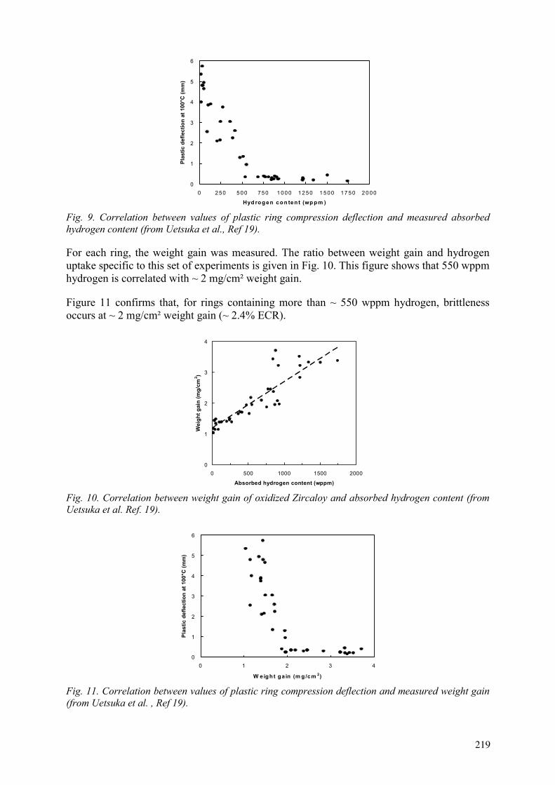
0
1
2
3
4
5
6
0 250 500 750 1 000 1 250 1 500 17 50 20 00
Hyd ro g en co n ten t (wp p m )
Plas
tic d
efle
ctio
n at
100
°C (m
m)
Fig. 9. Correlation between values of plastic ring compression deflection and measured absorbed hydrogen content (from Uetsuka et al., Ref 19).
For each ring, the weight gain was measured. The ratio between weight gain and hydrogen uptake specific to this set of experiments is given in Fig. 10. This figure shows that 550 wppm hydrogen is correlated with ~ 2 mg/cm² weight gain.
Figure 11 confirms that, for rings containing more than ~ 550 wppm hydrogen, brittleness occurs at ~ 2 mg/cm² weight gain (~ 2.4% ECR).
0
1
2
3
4
0 500 1000 1500 2000
Absorbed hydrogen content (wppm)
Wei
ght g
ain
(mg/
cm2 )
Fig. 10. Correlation between weight gain of oxidized Zircaloy and absorbed hydrogen content (from Uetsuka et al. Ref. 19).
0
1
2
3
4
5
6
0 1 2 3 4
W e ig h t ga in (m g /c m 2)
Plas
tic d
efle
ctio
n at
100
°C (m
m)
Fig. 11. Correlation between values of plastic ring compression deflection and measured weight gain (from Uetsuka et al. , Ref 19).
219
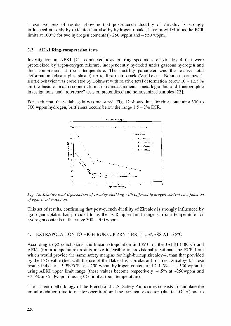
These two sets of results, showing that post-quench ductility of Zircaloy is strongly influenced not only by oxidation but also by hydrogen uptake, have provided to us the ECR limits at 100°C for two hydrogen contents (~ 250 wppm and ~ 550 wppm).
3.2. AEKI Ring-compression tests
Investigators at AEKI [21] conducted tests on ring specimens of zircaloy 4 that were preoxidized by argon-oxygen mixture, independently hydrided under gaseous hydrogen and then compressed at room temperature. The ductility parameter was the relative total deformation (elastic plus plastic) up to first main crack (Vrtilkova – Böhmert parameter). Brittle behavior was correlated by Böhmert with relative total deformation below 10 ~ 12.5 % on the basis of macroscopic deformations measurements, metallographic and fractographic investigations, and “reference” tests on preoxidized and homogenized samples [22].
For each ring, the weight gain was measured. Fig. 12 shows that, for ring containing 300 to 700 wppm hydrogen, brittleness occurs below the range 1.5 – 2% ECR.
Fig. 12. Relative total deformation of zircaloy cladding with different hydrogen content as a function of equivalent oxidation.
This set of results, confirming that post-quench ductility of Zircaloy is strongly influenced by hydrogen uptake, has provided to us the ECR upper limit range at room temperature for hydrogen contents in the range 300 – 700 wppm.
4. EXTRAPOLATION TO HIGH-BURNUP ZRY-4 BRITTLENESS AT 135°C
According to §2 conclusions, the linear extrapolation at 135°C of the JAERI (100°C) and AEKI (room temperature) results make it feasible to provisionally estimate the ECR limit which would provide the same safety margins for high-burnup zircaloy-4, than that provided by the 17% value (tied with the use of the Baker-Just correlation) for fresh zircaloy-4. These results indicate ~ 3.5%ECR at ~ 250 wppm hydrogen content and 2.5~3% at ~ 550 wppm if using AEKI upper limit range (these values become respectively ~4.5% at ~250wppm and ~3.5% at ~550wppm if using 0% limit at room temperature).
The current methodology of the French and U.S. Safety Authorities consists to cumulate the initial oxidation (due to reactor operation) and the transient oxidation (due to LOCA) and to
220
compare the sum to 17%. For example, 100 m initial oxide layer corresponds to ~ 65 mconsumed metal (Pilling – Bedworth ratio ~ 1.5); if the initial metal thickness is 570 m, the criterion applied to the transient oxidation will be 17 – (65x100)/570 5.5 %. For a Zircaloy-4 cladding, a 100 m corrosion oxide layer is known to correspond to ~500 wppm hydrogen uptake. Hence, the “conservatism” of the French and U.S. Safety Authorities provisional criteria is questionable. This result contradicts Waeckel’s opinion expressed at the Park-City meeting [23].
There is a need of tests with high-burnup Zry-4 to confirm and precise these results. A NRC-sponsored program is underway at ANL [4]. As JAERI and AEKI did not perform tests above the PCT criterion, there remains a need of complementary tests with specimen oxidized at higher temperatures.
5. CONCLUSIONS
In the 1973 ECCS Rule-Making Hearing, the U. S. Atomic Energy Commission (AEC) staff and commissioners were clearly reluctant to neglect the effect of mechanical constraints on the susceptibility of oxidized fuel cladding to thermal-shock fragmentation. Results from unconstrained quench tests were considered only corroborative; their use for regulatory purposes was not accepted.
The AEC staff and commissioners were of the opinion that retention of ductility was the best guarantee against potential fragmentation of fuel cladding under various types of not-so-well-quantified loading, such as thermal shock, bundle constraints, hydraulic, and seismic forces.
Primary rationale of the 17% oxidation criterion was retention of cladding ductility at temperatures higher than 275°F (135°C), i.e. the saturation temperature during reflood. The threshold equivalent cladding reacted (ECR) of 17% is tied with the use of the Baker-Just correlation. If a best-estimate correlation other than Baker-Just equation (e.g., Cathcart-Pawel correlation) had been used, the threshold ECR would have been <17%.
Investigations conducted after the 1973 Rule-Making Hearing show that for oxidation temperatures 1204°C, the 17% oxidation limit (calculated with Baker-Just correlation) is adequate to ensure survival of fully constrained cladding under quenching thermal shock. It was also shown that the 17% limit (ECR determined on the basis of measured phase layer thickness) is adequate to ensure resistance to 0.3-J impact failure on unirradiated Zircaloy cladding.
A major finding from tests performed after the 1973 Rule-Making Hearing shows that post-quench ductility is strongly influenced by not only oxidation but also hydrogen uptake. Significantly large hydrogen uptake can occur in some types of fuel cladding, during normal operation to high burnup, during breakaway oxidation at <1120°C, and, during LOCA transients, for localized regions near a rupture opening.
The extrapolation at 135°C of the results obtained for hydrided Zircaloy-4 cladding in the 1980s from Japan Atomic Energy Research Institute (JAERI) slow-ring-compression tests, and more recently from similar Hungarian Atomic Energy Research Institute (AEKI) tests shows that the transient ECR criterion must be significantly lower than 17% for high-burnup Zircaloy-4 and that current methodologies don’t provide the same safety margin for high-burnup low-tin Zircaloy-4, than that provided by the current ECR criterion for fresh Zircaloy-4. Considering these factors, it is recommended to perform tests to obtain a better
221
understanding of the effects of more realistic hydrogen uptake, on the post-quench ductility, in order to establish embrittlement thresholds that provide sufficient safety margin to high-burnup operation. Testing of other alloys, less subject to hydriding during operation, could also be useful.
ACKNOWLEDGEMENTS
The authors would like to express thanks to H. M. Chung for helpful discussions.
REFERENCES
[1] GRANDJEAN, C. et al., "Oxidation and quenching experiments with high burnup cladding under LOCA conditions," Proc. 26th Water Reactor Safety Information Meeting, Bethesda, USA, 26-28 October, 1998.
GRANDJEAN, C., "Oxidation and quenching experiments under simulated LOCA conditions with high burnup clad material," Proc. 24th Water Reactor Safety Information Meeting, Bethesda, USA, 21-23 October, 1996.
[2] NAGASE, F. et al., "Study on high burnup fuel behavior under a LOCA condition at JAERI," this meeting.
[3] OZAWA, M. et al., "Behavior of irradiated zircaloy4 fuel cladding under simulated LOCA conditions," Proc. 12th Symp. on Zirconium in the Nuclear Industry, Toronto, Canada, 15-18 June, 1998.
[4] CHUNG, H. et al., “Progress in ANL/USNRC/EPRI program on LOCA,” Proc. OECD/CSNI Topical meeting on LOCA fuel safety criteria, Aix-en-Provence, France, 22-23 March, 2001.
[5] HACHE, G. and Chung, H.M., “The History of LOCA Embrittlement Criteria,” Proc. 28th Water Reactor Safety Information Meeting, Bethesda, USA, 23-25 October, 2000.
[6] HACHE, G., “Rationale of the LOCA 10 CFR 50.46b criteria for zircaloy and comparison with E110 alloy”, Proc. OECD/CSNI Topical meeting on LOCA fuel safety criteria, Aix-en-Provence, France, 22-23 March, 2001.
[7] Report of Advisory Task Force on Power Reactor Emergency Cooling, TID-24226, 1967.
[8] General Design Criteria for Nuclear Power Plants, U.S. Code of Federal Regulations, Title 10, Part 50, Appendix A, 20 February, 1971, amended.
[9] ATOMIC ENERGY COMMISSION RULE-MAKING HEARING, Opinion of the Commission, Docket RM-50-1, 28 December, 1973.
[10] CHUNG, H.M. and KASSNER, T.F., Embrittlement Criteria for Zircaloy Fuel Cladding Applicable to Accident Situations in Light-Water Reactors, NUREG/CR-1344, January 1980.
[11] PARSONS, P.D. et al., The Deformation, Oxidation and Embrittlement of PWR Fuel Cladding in a Loss-of-Coolant Accident: A State-of-the-Art Report, CSNI Report 129, December 1986.
[12] ZUZEK, E. et al., "The H-Zr (hydrogen-zirconium) system," Bulletin of Alloy Phase Diagrams, 11 (1990) 385-395.
[13] ATOMIC ENERGY COMMISSION RULE-MAKING HEARING, Supplemental Testimony of the Regulatory Staff, Docket RM-50-1, 26 October, 1972.
[14] ATOMIC ENERGY COMMISSION RULE-MAKING HEARING, Concluding Statement of the Regulatory Staff, Docket RM-50-1, 16 April, 1973.
[15] HOBSON, D.O., and RITTENHOUSE, P. L., "Embrittlement of Zircaloy Clad Fuel Rods by Steam During LOCA Transients," ORNL-4758, Oak Ridge National Laboratory, January 1972.
222
[16] HOBSON, D.O., "Ductile-brittle behavior of Zircaloy fuel cladding," Proc. ANS Topical Mtg. on Water Reactor Safety, Salt Lake City, 26 March, 1973.
[17] UETSUKA, H. et al., "Failure-bearing capability of oxidized Zircaloy-4 cladding under simulated loss-of-coolant condition," J. Nucl. Sci. Tech. 20 (1983) 941-950.
[18] UETSUKA, H. et al., "Zircaloy-4 cladding embrittlement due to inner surface oxidation under simulated loss-of-coolant condition," J. Nucl. Sci. Tech. 18 (1981) 705-717.
Furuta, T. et al., “Ductility loss of Zircaloy cladding by inner-surface oxidation during high temperature transient,” J. Nucl. Sci. Tech. 18 (1981) 802-810.
[19] UETSUKA, H. et al., "Embrittlement of Zircaloy-4 due to oxidation in environment of stagnant steam," J. Nucl. Sci. Tech. 19 (1982), 158-165.
[20] KAWASAKI, S. et al., “Oxidation of Zircaloy-4 under high temperature steam atmosphere and its effect on ductility of cladding,” J. Nucl. Sci. Tech. 15 (1978) 589-596.
[21] MAROTI, L., “Ring-compression test results and experiments supporting LOCA PCT, oxidation and channel blockage criteria”, Proc. OECD/CSNI Topical meeting on LOCA fuel safety criteria, Aix-en-Provence, France, 22-23 March, 2001.
[22] BÖHMERT, J., “Embrittlement of ZrNb1 at room temperature after high-temperature oxidation in steam atmosphere”, Kerntechnik 57 (1992) No.1 55-58
BÖHMERT, J. ET AL., “Untersuchungen zur Hochtemperatur-Dampf-Oxidation von ZrNb1”, ZfK-743, Mai 1991.
[23] WAECKEL, N. et al., “Effects of in-reactor corrosion on the 17% LOCA criterion,” Proc. Light Water Reactor Fuel Performance Conference, Park-City, USA, 10-13 April, 2000.
223
DISCUSSION ON EXPERIMENTAL METHODS TO DERIVE LOCA SAFETY LIMITS
C. VITANZA OECD Halden Reactor Project, Norway
Abstract. This paper is intended to briefly discuss the experimental methods that are most commonly used to define LOCA safety limits. This discussion is made on the basis of what was done three decades ago for establishing current limits.Two methods have in particular been reviewed, i.e., the one based on embrittlement and ring compression tests and the one based on thermal shock during quenching of fuel rod simulator. These two tests may lead to quite different results, thus the choice between them is highly relevant.
1. INTRODUCTION AND SUMMARY
This paper is intended to briefly discuss the experimental methods that are most commonly used to define LOCA safety limits. This discussion is made on the basis of what was done three decades ago for establishing current limits 1, 2 .
Two methods have in particular been reviewed, i.e., the one based on embrittlement and ring compression tests and the one based on thermal shock during quenching of fuel rod simulator. These two tests may lead to quite different results, thus the choice between them is highly relevant.
High temperature tests in steam environment are needed to determine the LOCA safety criteria for materials different than Zircaloy-4 and for high burn-up applications. It is important in this context that the experimental methods used in different laboratories are compatible with each other such that the conclusions reached in different establishments can be harmonised with each other.
The paper briefly addresses the data representation and suggests a direct way to compare the safety limits derived from experiments with expected conditions based on LOCA code calculations. This is done on a temperature-time diagram (which in itself is nothing new) where the margin between the expected conditions and the safety limit can be visualised in a direct manner.
The paper also implies that embrittlement and ring compression tests should be considered for future LOCA experiments in that they appear to be more conservative than quench tests. Further, they are consistent with the method and database used to derive current criteria. If quench tests are used, one probably needs an in-depth justification for not using what constitutes the basis of current criteria. In any case, it would probably be wise that the nuclear community adheres to a commonly recognised methodology, in order to avoid risks of conflicting conclusions drawn from different experimental premises.
224
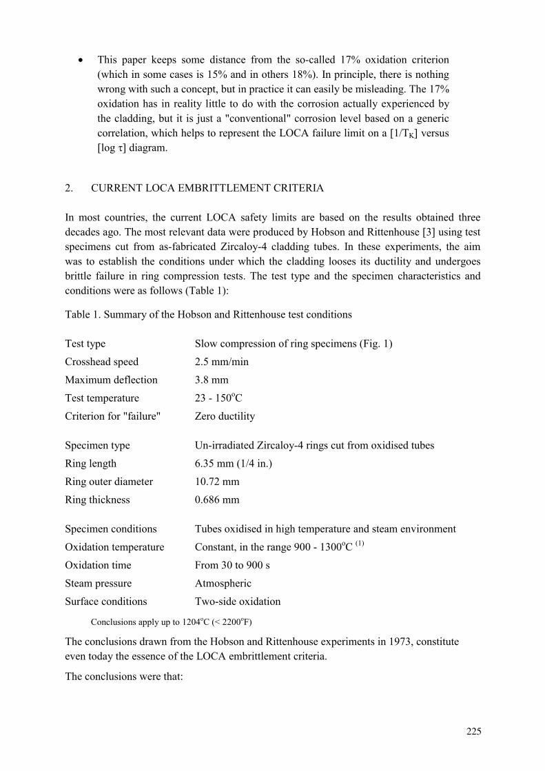
This paper keeps some distance from the so-called 17% oxidation criterion (which in some cases is 15% and in others 18%). In principle, there is nothing wrong with such a concept, but in practice it can easily be misleading. The 17% oxidation has in reality little to do with the corrosion actually experienced by the cladding, but it is just a "conventional" corrosion level based on a generic correlation, which helps to represent the LOCA failure limit on a 1/TK versus log diagram.
2. CURRENT LOCA EMBRITTLEMENT CRITERIA
In most countries, the current LOCA safety limits are based on the results obtained three decades ago. The most relevant data were produced by Hobson and Rittenhouse 3 using test specimens cut from as-fabricated Zircaloy-4 cladding tubes. In these experiments, the aim was to establish the conditions under which the cladding looses its ductility and undergoes brittle failure in ring compression tests. The test type and the specimen characteristics and conditions were as follows (Table 1):
Table 1. Summary of the Hobson and Rittenhouse test conditions
Test type Slow compression of ring specimens (Fig. 1)
Crosshead speed 2.5 mm/min
Maximum deflection 3.8 mm
Test temperature 23 - 150oC
Criterion for "failure" Zero ductility
Specimen type Un-irradiated Zircaloy-4 rings cut from oxidised tubes
Ring length 6.35 mm (1/4 in.)
Ring outer diameter 10.72 mm
Ring thickness 0.686 mm
Specimen conditions Tubes oxidised in high temperature and steam environment
Oxidation temperature Constant, in the range 900 - 1300oC (1)
Oxidation time From 30 to 900 s
Steam pressure Atmospheric
Surface conditions Two-side oxidation
Conclusions apply up to 1204oC (< 2200oF)
The conclusions drawn from the Hobson and Rittenhouse experiments in 1973, constitute even today the essence of the LOCA embrittlement criteria.
The conclusions were that:
225
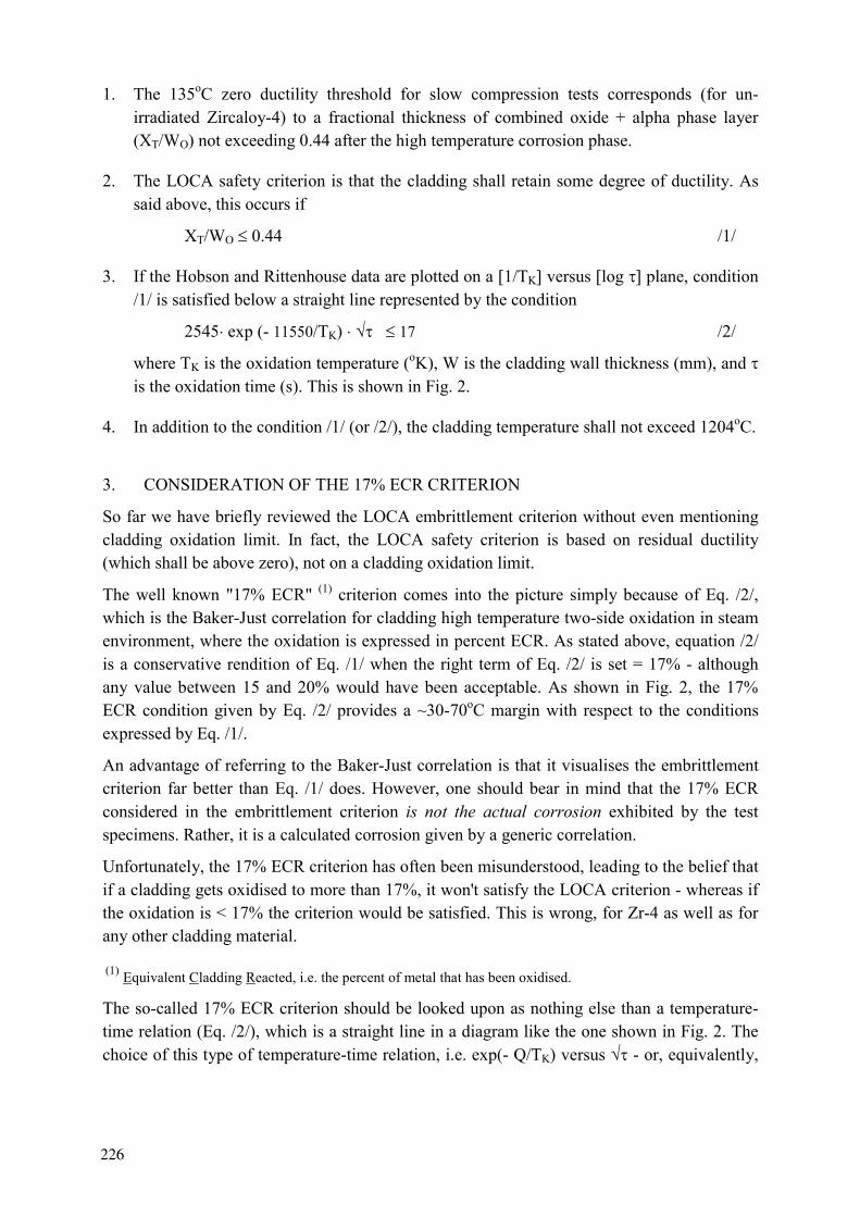
1. The 135oC zero ductility threshold for slow compression tests corresponds (for un-irradiated Zircaloy-4) to a fractional thickness of combined oxide + alpha phase layer (XT/WO) not exceeding 0.44 after the high temperature corrosion phase.
2. The LOCA safety criterion is that the cladding shall retain some degree of ductility. As said above, this occurs if
XT/WO 0.44 /1/
3. If the Hobson and Rittenhouse data are plotted on a 1/TK versus log plane, condition /1/ is satisfied below a straight line represented by the condition
2545 exp (- 11550/TK) 17 /2/
where TK is the oxidation temperature (oK), W is the cladding wall thickness (mm), and is the oxidation time (s). This is shown in Fig. 2.
4. In addition to the condition /1/ (or /2/), the cladding temperature shall not exceed 1204oC.
3. CONSIDERATION OF THE 17% ECR CRITERION
So far we have briefly reviewed the LOCA embrittlement criterion without even mentioning cladding oxidation limit. In fact, the LOCA safety criterion is based on residual ductility (which shall be above zero), not on a cladding oxidation limit.
The well known "17% ECR" (1) criterion comes into the picture simply because of Eq. /2/, which is the Baker-Just correlation for cladding high temperature two-side oxidation in steam environment, where the oxidation is expressed in percent ECR. As stated above, equation /2/ is a conservative rendition of Eq. /1/ when the right term of Eq. /2/ is set = 17% - although any value between 15 and 20% would have been acceptable. As shown in Fig. 2, the 17% ECR condition given by Eq. /2/ provides a ~30-70oC margin with respect to the conditions expressed by Eq. /1/.
An advantage of referring to the Baker-Just correlation is that it visualises the embrittlement criterion far better than Eq. /1/ does. However, one should bear in mind that the 17% ECR considered in the embrittlement criterion is not the actual corrosion exhibited by the test specimens. Rather, it is a calculated corrosion given by a generic correlation.
Unfortunately, the 17% ECR criterion has often been misunderstood, leading to the belief that if a cladding gets oxidised to more than 17%, it won't satisfy the LOCA criterion - whereas if the oxidation is < 17% the criterion would be satisfied. This is wrong, for Zr-4 as well as for any other cladding material.
(1) Equivalent Cladding Reacted, i.e. the percent of metal that has been oxidised.
The so-called 17% ECR criterion should be looked upon as nothing else than a temperature-time relation (Eq. /2/), which is a straight line in a diagram like the one shown in Fig. 2. The choice of this type of temperature-time relation, i.e. exp(- Q/TK) versus - or, equivalently,
226

1/TK versus log - is due to the fact that the underlying phenomenon leading to cladding brittleness is indeed cladding oxidation and this can be expressed as ECR = A exp(- Q/TK)
It makes then a lot of sense to plot embrittlement data in a diagram like the one in Fig. 2. As already said, however, the "17% ECR" limit is just a straight line in that diagram, separating the brittle from the ductile data. With reference to the Baker-Just correlation, such straight line corresponds to ~17% ECR. One could have used another correlation (1), and the percent ECR limit would have been different.
4. PROGRESS AFTER 1973
Significant research on LOCA embrittlement has been conducted after the establishment of the LOCA safety criteria summarised in section 2. In particular, studies have been made on a variety of effects, such as (see review in ref. 1 and 2):
- Effect of cooling rate. ANL experiments showed that slow-cooled specimens retained more ductility than fast-cooled specimens.
- Effect of local hydrogen uptake. JAERI experiments were made with pressurised tubes aiming to simulate the ballooning phase. High levels of hydrogen uptake were detected at the necked regions above and below the ballooning region, affecting local ductility.
- Effect of specimen type and test method. In some tests as those carried out at JAERI or in Russian research establishments, the test specimens, instead of rings, consisted of tubes simulating a fuel rod (Fig. 3). The tubes were often filled with alumina pellets as fuel simulant. Instead of slow compression tests, the experiments consisted of subjecting such fuel rod simulators to actual reflood and quench after the high temperature oxidation phase. Instead of zero ductility, the criterion was based on failure of the simulator during quenching. The outcome of such quench tests can be very different from slow compression tests. As shown in Fig. 4, which refers to tests on VVER cladding, the slow compression tests are normally far more conservative than the quench tests. The conclusion is apparent: The choice of one test method or another may lead to quite different conclusions.
- Effect of constraints. Quench tests made at JAERI with fuel simulators, show that the outcome can be dramatically affected by the presence or not of axial constraints. This is clearly visible in Fig. 5, which show that simulators with constraints fail at oxidation levels three times lower than those for simulators without constraints. The question as to whether reference LOCA tests should be made with or without constraints is not irrelevant. However, no recommendations exist on this subject as yet.
(1) The Baker and Just correlation is rather conservative and is not necessarily the best one, not even for Zr-4. The term
2545 exp(-11550/TK) in Eq.2 corresponds to the Baker and Just correlation, i.e. ECR =2*873/W exp(-11550/Tk) ,
where the factor 2 is due to double side oxidation and W=0.686 is the clad thickness in the Hobson-Rittenhouse tests
227
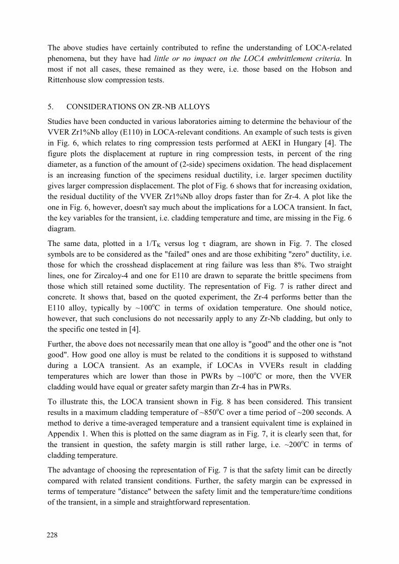
The above studies have certainly contributed to refine the understanding of LOCA-related phenomena, but they have had little or no impact on the LOCA embrittlement criteria. In most if not all cases, these remained as they were, i.e. those based on the Hobson and Rittenhouse slow compression tests.
5. CONSIDERATIONS ON ZR-NB ALLOYS
Studies have been conducted in various laboratories aiming to determine the behaviour of the VVER Zr1%Nb alloy (E110) in LOCA-relevant conditions. An example of such tests is given in Fig. 6, which relates to ring compression tests performed at AEKI in Hungary 4 . The figure plots the displacement at rupture in ring compression tests, in percent of the ring diameter, as a function of the amount of (2-side) specimens oxidation. The head displacement is an increasing function of the specimens residual ductility, i.e. larger specimen ductility gives larger compression displacement. The plot of Fig. 6 shows that for increasing oxidation, the residual ductility of the VVER Zr1%Nb alloy drops faster than for Zr-4. A plot like the one in Fig. 6, however, doesn't say much about the implications for a LOCA transient. In fact, the key variables for the transient, i.e. cladding temperature and time, are missing in the Fig. 6 diagram.
The same data, plotted in a 1/TK versus log diagram, are shown in Fig. 7. The closed symbols are to be considered as the "failed" ones and are those exhibiting "zero" ductility, i.e. those for which the crosshead displacement at ring failure was less than 8%. Two straight lines, one for Zircaloy-4 and one for E110 are drawn to separate the brittle specimens from those which still retained some ductility. The representation of Fig. 7 is rather direct and concrete. It shows that, based on the quoted experiment, the Zr-4 performs better than the E110 alloy, typically by ~100oC in terms of oxidation temperature. One should notice, however, that such conclusions do not necessarily apply to any Zr-Nb cladding, but only to the specific one tested in 4 .
Further, the above does not necessarily mean that one alloy is "good" and the other one is "not good". How good one alloy is must be related to the conditions it is supposed to withstand during a LOCA transient. As an example, if LOCAs in VVERs result in cladding temperatures which are lower than those in PWRs by ~100oC or more, then the VVER cladding would have equal or greater safety margin than Zr-4 has in PWRs.
To illustrate this, the LOCA transient shown in Fig. 8 has been considered. This transient results in a maximum cladding temperature of ~850oC over a time period of ~200 seconds. A method to derive a time-averaged temperature and a transient equivalent time is explained in Appendix 1. When this is plotted on the same diagram as in Fig. 7, it is clearly seen that, for the transient in question, the safety margin is still rather large, i.e. ~200oC in terms of cladding temperature.
The advantage of choosing the representation of Fig. 7 is that the safety limit can be directly compared with related transient conditions. Further, the safety margin can be expressed in terms of temperature "distance" between the safety limit and the temperature/time conditions of the transient, in a simple and straightforward representation.
228
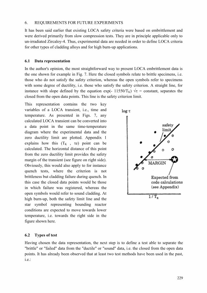
6. REQUIREMENTS FOR FUTURE EXPERIMENTS
It has been said earlier that existing LOCA safety criteria were based on embrittlement and were derived primarily from slow compression tests. They are in principle applicable only to un-irradiated Zircaloy-4. Thus, experimental data are needed in order to define LOCA criteria for other types of cladding alloys and for high burn-up applications.
6.1 Data representation
In the author's opinion, the most straightforward way to present LOCA embrittlement data is the one shown for example in Fig. 7. Here the closed symbols relate to brittle specimens, i.e. those who do not satisfy the safety criterion, whereas the open symbols refer to specimens with some degree of ductility, i.e. those who satisfy the safety criterion. A straight line, for instance with slope defined by the equation exp(- 11550/TK) = constant, separates the closed from the open data points. This line is the safety criterion limit.
This representation contains the two key variables of a LOCA transient, i.e., time and temperature. As presented in Figs. 7, any calculated LOCA transient can be converted into a data point in the same time-temperature diagram where the experimental data and the zero ductility limit are plotted. Appendix 1 explains how this ( K , e) point can be calculated. The horizontal distance of this point from the zero ductility limit provides the safety margin of the transient (see figure on right side). Obviously, this would also apply to for instance quench tests, where the criterion is not brittleness but cladding failure during quench. In this case the closed data points would be those in which failure was registered, whereas the open symbols would refer to sound cladding. At high burn-up, both the safety limit line and the star symbol representing bounding reactor conditions are expected to move towards lower temperature, i.e. towards the right side in the figure shown here.
6.2 Types of test
Having chosen the data representation, the next step is to define a test able to separate the "brittle" or "failed" data from the "ductile" or "sound" data, i.e. the closed from the open data points. It has already been observed that at least two test methods have been used in the past, i.e.:
229
1. Ring compression tests after two-side high temperature oxidation of tubes in presence of steam. The criterion here is brittle versus ductile fracture of the ring specimens.
2. Tests with simulators subjected to high temperature oxidation and subsequent quench. The criterion here is failure versus survival of the simulator during quenching.
The ring compression tests and brittleness criterion have the advantage of being consistent with the experimental basis of current LOCA criteria. Further, these tests appear to be conservative with respect to simulator quench tests. If this type of test is chosen for testing of advanced alloys, the test procedure should be the same as in Hobson and Rittenhouse tests. Further, an objective manner for determining "zero" ductility is needed, for instance based on a minimum crosshead displacement of the compression test machine. For testing of high burn-up cladding, one should consider whether the cladding tubes should be exposed to two-side or one-side oxidation and whether the cladding tubes should be defuelled or not. Probably, the most straightforward method would be to defuel the tubes and subject them to two-side oxidation. This method is consistent with the database of current criteria and conservative in that corrosion takes place on both sides of the cladding. If this method is chosen, one might need to define a suitable procedure for defuelling and the requirements on tube ID surface conditions.
For quench tests with simulators, the consideration is that these tests lead to less conservative conclusions than current LOCA criteria, which are based on brittleness (at least if no constraints are applied). For applications to high burn-ups one should decide if segments of actual fuel rods should constitute the simulator or if this should be re-constituted with for instance alumina pellets, as done for unirradiated simulators. In any case, one would need to define the rod inner pressure and the plenum volume. Further, the question remains as to whether constraints need to be applied or not.
In summary, it is possible that the use of simulators and quench tests would give rise to more questions than it provides answers. The main concern is that it deviates from the embrittlement criteria, which underwent a very in-depth scrutiny when they were established and which have been the basis for LOCA assessments for three decades. Secondly, quench tests without constraints are less conservative than embrittlement test. Thirdly, the need and level of axial constraints is to be justified and specified.
A possibility to consider could be to remain with ring compression/embrittlement tests as the experimental basis for LOCA criteria for advanced alloys and high burn-up, but to perform confirmatory tests with simulators without and with constraints. The latter would be mainly meant to confirm that brittleness criteria are indeed conservative and that no unforeseen phenomena arise during quenching. In any case, any test should be performed with un-irradiated Zircaloy-4 material as reference. A Zr-4 "material bank" should perhaps be established to this end, such that at least the Zr-4 reference would be the same for various tests and test establishments.
230

6.3 Ranges of oxidation temperature and time
Code calculations of LOCA transients for actual cores and for realistic reactor configurations should constitute the basis for selecting the experimental range of oxidation temperature and time.
For as-fabricated materials, the temperature range to be considered is indicatively 800-1200oC. The corresponding time ranges are indicatively:
1000 - 30000 s at 800oC 100 - 5000 s at 1000oC 10 - 500 s at 1200oC
For high burn-up materials one might need to shift the range towards lower temperatures, depending on what LOCA code calculations give as expected peak cladding temperature.
6.4 Integral tests at high burn-up
While this paper discusses the cladding tests needed to determine LOCA safety criteria, one should recognise that additional LOCA relevant phenomena should be addressed in different types of experiments.
Some basic phenomena need to be further explored and characterised. One is the possibility of fuel fragment relocation into the ballooning area. The consideration here is that if such relocation occurs, it would lead to additional decay heat production in the ballooning area. A second process that needs further assessments is the fission gas release during the high temperature transient, as this may contribute to sustain ballooning. A third one is the axial gas transport, which is very limited at high burn-up and might not be sufficient to sustain ballooning.
These phenomena are not discussed further here, although they can be very relevant ones and even have implications on the safety criteria. They will be addressed among others, in tests planned at Halden.
6.5 Final remark
One should again notice that in this outline of requirements for future experiments, the 17% ECR (or 15%, or 18%) has not even been mentioned. As discussed earlier it really makes little or no sense to pursue the "17% ECR" concept, which is a rather volatile one already for fresh Zr-4 and becomes even more hazy for non Zr-4 cladding and for high burn-up. There is no need to consider 17%, or any other percent ECR in LOCA criteria, except perhaps for using the Baker-Just ECR as a relative indicator of where the safety limits lay in a 1/TK versus log
diagram.
231

REFERENCES 1 G. HACHE, Rationale of the LOCA Criteria for Zircaloy and Comparison with E110
Alloy. Paper presented at the CSNI Topical Meeting on Fuel Safety Criteria, Aix-en-Provence, France, March 2001.
2 G. HACHE, H.M. CHUNG, The History of LOCA Embrittlement Criteria. Paper presented at the 28th WRSM, Bethesda, USA, October 2000.
3 D.O. HOBSON, P.L. RITTENHOUSE, Embrittlement of Zircaloy-Clad Fuel Rods by Steam During LOCA Transients. ORNL 4758, UC-80-Reactor Technology, January 1972.
4 L. MAROTI, Ring-Compression Test Results and Experiments Supporting LOCA PCT, Oxidation and Channel Blockage Criteria. Paper presented at the CSNI Topical Meeting on Fuel Safety Criteria, Aix-en-Provence, France, March 2001.
5 H. UETSUKA, F. NAGASE, Recent Research on High Burn-up Fuel Behaviour During a LOCA at JAERI. Paper presented at the CSNI Topical Meeting on Fuel Safety Criteria, Aix-en-Provence, France, March 2001.
6 Z. HOZER, Personal communication, May 2001.
232
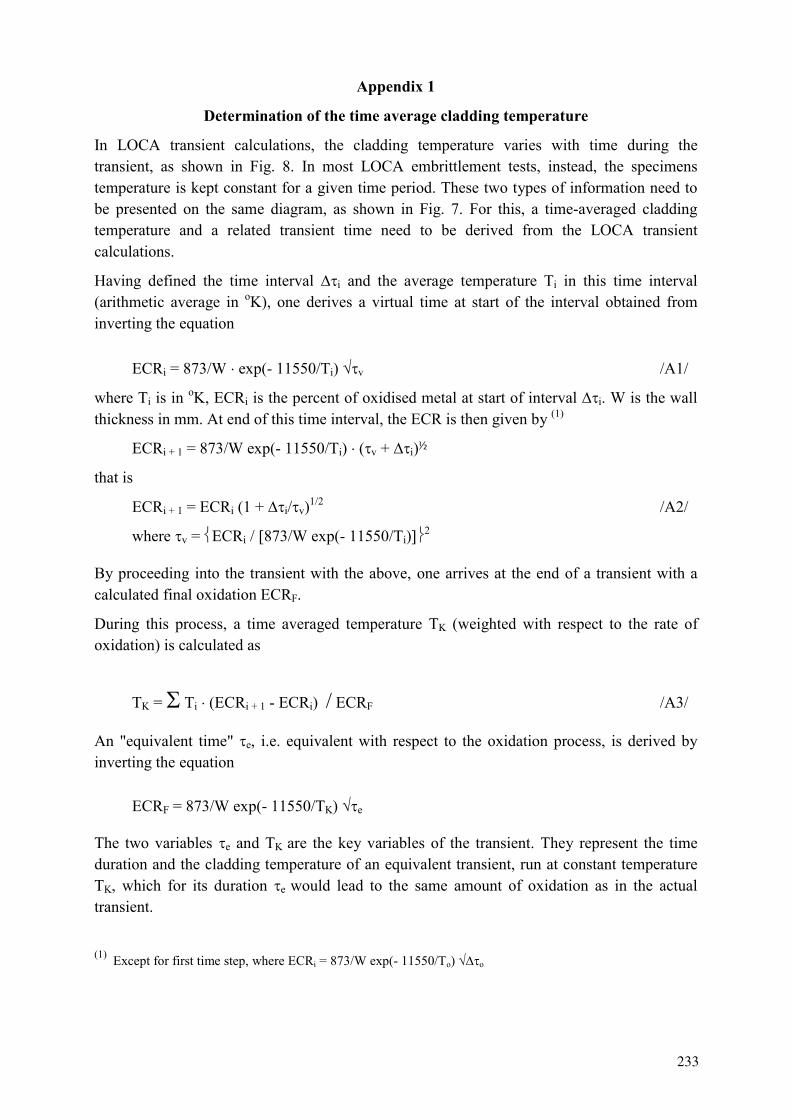
Appendix 1
Determination of the time average cladding temperature
In LOCA transient calculations, the cladding temperature varies with time during the transient, as shown in Fig. 8. In most LOCA embrittlement tests, instead, the specimens temperature is kept constant for a given time period. These two types of information need to be presented on the same diagram, as shown in Fig. 7. For this, a time-averaged cladding temperature and a related transient time need to be derived from the LOCA transient calculations.
Having defined the time interval i and the average temperature Ti in this time interval (arithmetic average in oK), one derives a virtual time at start of the interval obtained from inverting the equation
ECRi = 873/W exp(- 11550/Ti) v /A1/
where Ti is in oK, ECRi is the percent of oxidised metal at start of interval i. W is the wall thickness in mm. At end of this time interval, the ECR is then given by (1)
ECRi + 1 = 873/W exp(- 11550/Ti) ( v + i)½
that is
ECRi + 1 = ECRi (1 + i/ v)1/2 /A2/
where v = ECRi / 873/W exp(- 11550/Ti) 2
By proceeding into the transient with the above, one arrives at the end of a transient with a calculated final oxidation ECRF.
During this process, a time averaged temperature K (weighted with respect to the rate of oxidation) is calculated as
K = Ti (ECRi + 1 - ECRi) / ECRF /A3/
An "equivalent time" e, i.e. equivalent with respect to the oxidation process, is derived by inverting the equation
ECRF = 873/W exp(- 11550/ K) e
The two variables e and K are the key variables of the transient. They represent the time duration and the cladding temperature of an equivalent transient, run at constant temperature
K, which for its duration e would lead to the same amount of oxidation as in the actual transient.
(1) Except for first time step, where ECRi = 873/W exp(- 11550/To) o
233
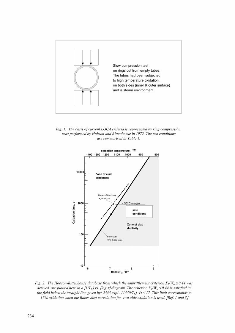
Fig. 2. The Hobson-Rittenhouse database from which the embrittlement criterion XT/Wo 0.44 was derived, are plotted here in a 1/TK vs. log diagram. The criterion XT/Wo 0.44 is satisfied in
the field below the straight line given by: 2545 exp(- 11550/TK) 17. This limit corresponds to 17% oxidation when the Baker-Just correlation for two-side oxidation is used. Ref. 1 and 3
Fig. 1. The basis of current LOCA criteria is represented by ring compression tests performed by Hobson and Rittenhouse in 1972. The test conditions
are summarised in Table 1.
Slow compression teston rings cut from empty tubes.The tubes had been subjectedto high temperature oxidation,on both sides (inner & outer surface)and is steam environment.
6 7 8 910
100
1000
10000
1400 1300 1200 1100 1000 900oxidation temperature, OC
Oxi
datio
n tim
e, s
10000/T K, OK-1
800
safeconditions
~ 50OC margin
Hobson-Rittenhouse XT/Wo=0.44
Baker-Just17% 2-side oxide
Zone of cladductivity
Zone of cladbrittleness
234
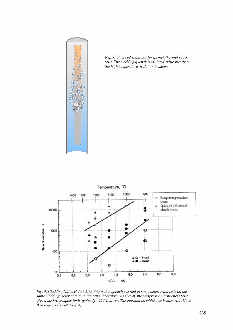
Fig. 4. Cladding "failure" test data obtained in quench test and in ring compression tests on the same cladding material and in the same laboratory. As shown, the compression/brittleness tests give a far lower safety limit, typically ~250oC lower. The question on which test is most suitable is thus highly relevant. (Ref. 4)
Fig. 3. Fuel rod simulator for quench/thermal shock tests. The cladding quench is initiated subsequently to the high temperature oxidation in steam.
235
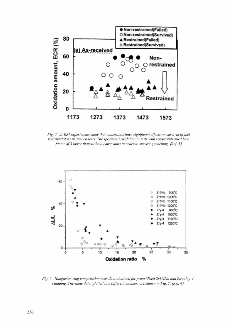
Fig. 5. JAERI experiments show that constraints have significant effects on survival of fuel rod simulators in quench tests. The specimens oxidation in tests with constraints must be a
factor of 3 lower than without constraints in order to survive quenching. Ref. 5
Fig. 6. Hungarian ring compression tests data obtained for preoxidised Zr1%Nb and Zircaloy-4 cladding. The same data, plotted in a different manner, are shown in Fig. 7. Ref. 4
236
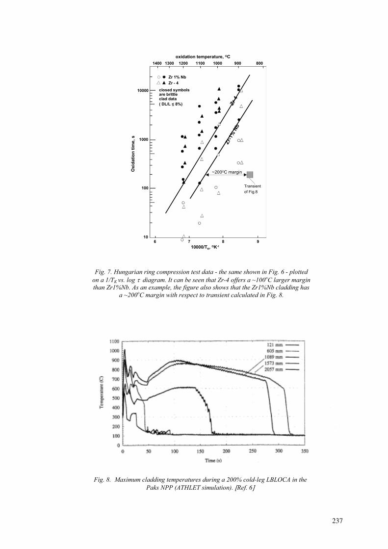
Fig. 7. Hungarian ring compression test data - the same shown in Fig. 6 - plotted on a 1/TK vs. log diagram. It can be seen that Zr-4 offers a ~100oC larger margin than Zr1%Nb. As an example, the figure also shows that the Zr1%Nb cladding has
a ~200oC margin with respect to transient calculated in Fig. 8.
Fig. 8. Maximum cladding temperatures during a 200% cold-leg LBLOCA in the Paks NPP (ATHLET simulation). Ref. 6
6 7 8 910
100
1000
10000
1400 1300 1200 1100 1000 900oxidation temperature, OC
Zr 1% NbZr - 4
closed symbolsare brittleclad data
Zr-4
Zr-1
%Nb
Oxi
datio
n tim
e, s
10000/TK, OK-1
800
~200OC margin
( DL/L < 8%)
Transient of Fig.8
237

HIGH BURNUP PHENOMENA RELEVANT FOR LOCA (Session 4)
Chairperson
G. RÖNNBERG Sweden

FISSION GAS RELEASE UNDER FAST TRANSIENT AND LOCA CONDITIONS: ANALYTICAL DEVICES IMPLEMENTED AT COMMISSARIAT A L’ENERGIE ATOMIQUE
Y. PONTILLON, S. RAVEL CEA Grenoble, Grenoble, France
D. PARRAT, M.P. FERROUD-PLATTET CEA Cadarache, Saint Paul Lez Durance, France
Y. GUÉRIN CEA Cadarache, Saint Paul Lez Durance, France
Abstract. R&D programs in support to general policy about exploitation of nuclear energy, developed in France these past years, highly promote studies about reactor safety on normal operating conditions as well as in accidental conditions. More recently, increasing interest for Fission Gas Release (FGR) studies in LOCA and fast transient conditions enabled starting of many research programs in CEA and particularly in Nuclear Energy Directorate (DEN). Within this context, the Fuel Studies Department (DEC) acquired an important theoretical as well as experimental experience. In order to achieve this competence, the Department equipped itself with specific technical facilities set up in very high activity hot cells, in particular at the CEA Grenoble. The researchers of the Department have a set of thermal treatment devices, including a vacuum furnace and a controlled atmosphere one (helium, air). These devices are associated to on line quantitative gamma spectrometry and gas chromatography coupled with a mass spectrometer, in order to measure emitted gas. The greatest asset of such an installation is to ensure a high analytical experiments rate, and as a consequence to make parametrical approach of planned studies easier. This is perfectly illustrated by two programs that are occurring this year, linked to LOCA and fast transient. In these cases, parametric analysis of fuel types, of their micro-structures (including MOX fuel), of burn-up influence, of thermal sequence imposed on the fuel sample was realized. Even though the reproduction of LOCA and/or fast transient conditions, occurring in nuclear power reactors, is only partial with this type of facilities, the realized tests enable to identify and quantify many physical parameters. This capability brings out important mechanisms promoting FGR, and permits to set up physical laws.
1. INTRODUCTION
Since many years, Research and Development (R and D) programs on nuclear fuel behaviour under neutron flux both in normal operation or during accidental conditions are carried out through joint actions by Commissariat à l’Energie Atomique (CEA), Electricité de France (EDF), Framatome-ANP and Nuclear Safety and Protection Institute (IPSN).
The main goals of these programmes are to study behaviour of new fuels, or to verify behaviour of standard fuels at higher burn-up, in response to EDF objectives concerning fuel management.
With respect of safety criteria, these objectives are mainly devoted:
- to increase burn-up for UO2 and MOX fuels: next step is the “MOX parity program”. Its goal is to reach a maximum discharge burn-up of 52 GWd.thm
-1 for MOX and UO2 fuel assemblies,
- to improve plants operational flexibility,
- to adapt fuel management regarding the fuel cost saving aspect.
241

Most of the R and D directions presently deal with three main programmes:
- study of fuel behaviour during fast transients and accidental conditions: Severe accidents, Reactivity Insertion Accidents (RIA) or Loss of Coolant Accident (LOCA) for example,
- a better understanding of MOX fuel properties and behaviour, and specially to complete experimental data acquisition on high burn-up fuel,
- improvement of fuel behaviour prediction, thanks to analytical in pile or in hot cell experiments, and improved physical models.
Within these frameworks, a special emphasis has been put on improvement of general knowledge on fuel behaviour in order to mitigate radiological consequences of a nuclear accident. Consequently, a lot of experimental programmes have been performed or are currently in progress at the Nuclear Energy Directorate (DEN) leading to a large database regarding the release of Fission Products (FP) with a special emphasis to the fission gases.
This database is used:
- to define the fission product (FP) “source term” out of the damaged rods during a given type of accidental sequence,
- to verify if existing safety criteria are well adapted to new fuels or to new management of standard fuels. If not, it leads to define evolution of these safety criteria,
- to enhance models predicting behaviour of various fuels during an accidental sequence, thanks to the understanding and quantifying of the basis mechanisms.
The present communication focus, in the first part, on the characteristics of the two main types of experiments that are carried out at the DEN concerning Fission Gas Release (FGR). The second part is devoted to the description of the corresponding experimental facility implemented at the CEA/DEN for fast transient and LOCA reproductions, and to the discussion about its performance and the accuracy of the results. As examples, we present some results gained thanks to this device.
2. MAIN OUTLINES OF FISSION GAS RELEASE EXPERIMENTAL PROGRAMMES
As described in the introduction, two main types of experimental programmes are carried out at the DEN. They can be defined as “global in-pile experiment” and “analytical experiments in hot cells”.
2.1. Global in-pile experiments
A global in-pile experiment concerns a unique experimental rod or a bundle. It often consists of three steps. First of all, the re-irradiation of a short experimental fuel rod in nominal conditions, then the accidental sequence achievement and, finally, the post-test examinations.
242

2.1.1. Re-irradiation of a short experimental fuel rod in nominal conditions
Fissile stack of the rod is made of fresh fuel, or has been already irradiated in power reactor. In this second case, experimental rod is manufactured thanks to the “Fabrice” process currently used at CEA. Generally the rod is instrumented with thermocouples on the clad or in the centre of an extremity pellet, and with a pressure gauge.
Re-irradiation lasts generally two cycles of the research reactor OSIRIS, located at CEA Saclay. It takes place in an instrumented irradiation device connected to a out-of-pile section. Main goals of this reirradiation is to create short and intermediate half-lives FP again, and to find the same fuel conditioning as the one reached at the in power reactor end of life. A few days after the first cycle, a longitudinal gamma scanning is performed thanks to a bench located in the reactor pool, in order to:
- adjust the fissile power time history supplied by neutron dosimetry,
- quantify precisely the fission products inventory present inside the rod,
- verify axial distributions of volatile and non-volatile fission products, and detect possible local or global depletion.
2.1.2. Accidental sequence achievement
Accidental sequence is generally achieved during the second irradiation cycle, after a time depending of the goals of the programme. The most representative initial state of the fuel has obviously to be reached just before the accidental sequence beginning.
An important goal of this kind of sequence is to reproduce experimental parameters time histories as close as possible as those expected during a real accident occurring in-power reactor, with very few possibilities to modify some parameters during the sequence.
For example, temperature evolution is reproduced thanks to fissile power variations, and it is possible to uncover or to reflood the experimental rod.
After sequence, released fission products out of the rod are measured on specific parts of the in-pile section: upper gaseous blanket (noble gases), loop water (noble gases, volatile and non volatile fission products, actinides…), and walls of the section (deposited FP and actinides).
However, a maximum number of effects is taken into account concerning the FGR: initial FP distribution in the matrix, FP release out of grains and out of grain boundaries, axial transfer in the fuel-clad gap (specially at high burn-up when the gap is normally closed) partially or totally filled with water or vapour, clad behaviour and clad failure morphology...
As the sequence is generally performed during irradiation, it is possible to monitor FP with very short half-lives. The measured evolution of the Released Fraction (FR) versus the radiological constant of the isotopes leads to important information concerning release mechanisms and kinetics.
243
2.1.3. Post-test examinations
Post-test examinations programme on the fuel rod give useful information on the global behaviour of the rod and on the fuel microstructure evolution.
Classical examinations are generally carried out on the fuel rod: visual and photographic inspection, metrology, longitudinal gamma scanning on long half-life isotopes not released during the sequence, clad oxide thickness,…
Fuel microstructure evolution is monitored thanks to cuts at different elevations of the fuel stack and extraction of fuel samples. Specific observation devices are then used in hot cells: metallographic inspection, Scanning Electron Microscopy (SEM) with elementary analysis, fractography, Electron Probe Micro Analysis (EPMA)…
2.1.4. Interest and limitations of a global experiment
As detailed here above, this kind of experiment represents the best way for reproduction at a small scale of a transient or a LOCA accident as it is expected in a power reactor. This remark concerns the number of experimental parameters taken into account, but also the type of results gained, such as the global behaviour of the rod, or the number of radioactive or stable FP of which FGR is measured.
However, such sequence is complex and long to be prepared. All results are obtained only after the sequence, and possibility to test an another experimental parameter obliges to reproduce an another sequence. This second preparation lasts generally several months.
Consequently the cost is high and only a few experiments are carried out.
2.2. Analytical experiments in hot cells
In this case, the approach is very different but complementary of a global experiment. It concerns either micro-samples, or pellet fragments, or a single, or a short stack constituted by a very few number of fuel pellets. If this pellet or stack is already pre-irradiated in a power reactor, the clad is kept, and a rod section is directly tested.
The corresponding experimental programme consists also in three steps: re-irradiation in a research reactor, transfer in hot cells Laboratory and test performance with on-line measurements, and post-test examinations.
2.2.1. Re-irradiation in a research reactor
This first step is not necessary, if only long half-life and stables isotopes have to be measured. Re-irradiations last generally less than one cycle of the research reactor OSIRIS (this means between a few and roughly twenty days).
If the section is extracted from an experimental rod, or if it is made of fresh fuel, re-irradiation of this rod can be performed:
- in conditions representative of those occurring in a power reactor. In this case, initial gas fission distribution in the pellet can be also fully representative of PWR
244
conditions, specifically the inventory ratio intragranular/grain boundaries for radioactive and stables FP. However, it needs a specific and relatively complex irradiation device, such as the one used for a global experiment.
- at low linear heat generation rate (10 to 25 W.cm-1). This permits to create short and intermediate half-life FP. Due to the low power and the short re-irradiation time, these FP are located inside the fissile grains, in intra-granular position. Besides irradiation device is now considerably simpler.
2.2.2. Transfer in hot cells Laboratory and test performance with on-line measurements
Decay time and transport of the re-irradiated section from the research reactor to the hot cells Laboratory have to be short if measurement of intermediate half-lives FP is interesting for the goals of the programme. It is currently possible to receive the stack 2 or 3 days after the end of the re-irradiation.
After reception, a longitudinal gamma scanning is carried out, in order to adjust the fissile power of the re-irradiation and to calculate the precise inventory of the FP, specially for noble gases.
After that, the accidental sequence can be carried out:
- either on the entire section. Test occurs after a few days of decay time,
- or on short samples or micro-samples. In this case cuttings or drillings of the re-irradiated stack are performed prior to the campaign of tests. This campaign occurs one or two weeks after the end of the re-irradiation.
For this purpose, sample is put in a devoted furnace. Accidental sequence consists in the reproduction of the temperature history expected in a power reactor, with a controlled atmosphere (presence, or not, of oxygen, water vapour,…). In this case, experimental parameters are precisely fixed and monitored during the sequence.
Sample is continuously swept by a gas flow (helium or air for example), and FP are measured in this gas by on-line gamma spectrometry and, after, by other means. More details are presented in § 3-1 below.
2.2.3. Post-test examinations
After sequence, some samples are examined by non destructive and destructive PIE: longitudinal or radial metallographic inspection, fractography, SIMS,…. such as for the global experiment. It is also possible to perform gamma tomography.
Main goals of these examinations are:
- to appreciate the evolution of the FP distribution, especially for noble gases, thanks to similar examinations carried out on a reference sample (re-irradiated or not, but not tested),
- to detect microstructure changes of the matrix, especially in terms of cracks distribution and pellet embrittlement.
245
2.2.4. Interest and limitations of analytical experiments
Through an analytical programme, reproduction of fast transients or a LOCA sequence, as expected in a power reactor, is only partial. Some steps of the accidental sequence can not be reproduced, such as, for a LOCA:
- the initial step (roughly a dozen of seconds) during which the radial temperature gradient in the pellet is important,
- the final step, corresponding to the reflooding of the rod.
However, quantitative effects of these steps on FP release are deduced from calculations.
The standard measurement concerns radioactive and stable noble gases. Measurement of volatile and non-volatile FP (iodine and caesium isotopes,…) is more complex and, for this purpose, the accidental sequence is performed in a specific device, as for the HEVA-VERCORS programme [1], [2], [3], [4].
However, such analytical tests are easy to prepare and to set up. When several samples can be re-irradiated at the same time and are available, it is possible to test, during a same campaign, the influence of the following parameters on the FP release:
- time history of the sample temperature (elevation rate, maximum value, plateau duration,…),
- type of the fuel (comparison MOX –UO2), and the microstructure (case of the MOX fuel),
- burn-up value,
- furnace atmosphere composition.
Moreover, detection and quantification of short or intermediate half-life FP permit to determine the contribution of intra-granular FP to the global release.
This large database enables to identify parameters which promote the FP release and specially the FGR. This leads to release mechanisms identification and quantification [5], and permits to set up physical laws which will be introduced in codes, in order to enhance or optimise existing models [6], [7].
3. DESCRIPTION OF THE THERMAL ANALYSES FACILITY IMPLEMENTED AT CEA/DEN FOR FAST THERMAL TRANSIENTS AND LOCA REPRODUCTIONS
Due to the scope of this meeting, we will focus now this presentation on an experimental facility used at DEN to set up reproduction of thermal transients and LOCA sequences: the thermal analyses facility. This facility is used for several years at CEA Grenoble, in the hot cell Laboratory LAMA, in order to fulfil several analytical programmes on FGR, such as the ADAGIO programme.
This facility has been already presented [8] and the first results obtained with the ADAGIO programme discussed [9]. So the following presentation will be relatively brief. In order to
246
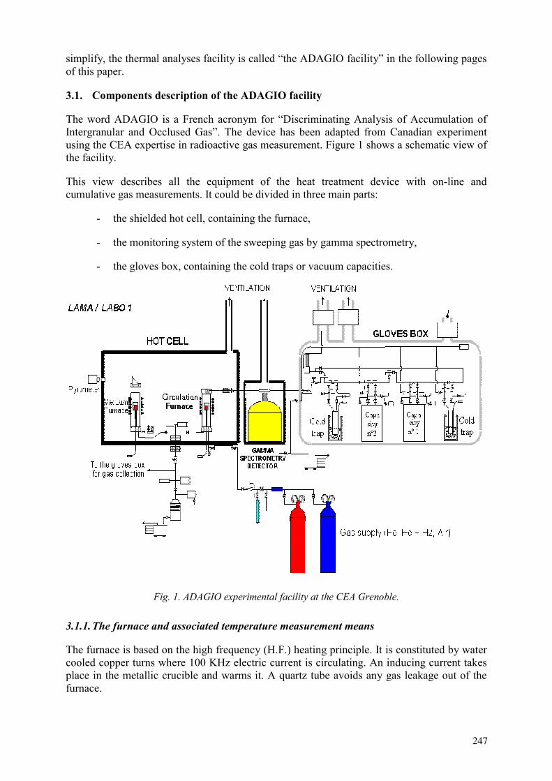
simplify, the thermal analyses facility is called “the ADAGIO facility” in the following pages of this paper.
3.1. Components description of the ADAGIO facility
The word ADAGIO is a French acronym for “Discriminating Analysis of Accumulation of Intergranular and Occlused Gas”. The device has been adapted from Canadian experiment using the CEA expertise in radioactive gas measurement. Figure 1 shows a schematic view of the facility.
This view describes all the equipment of the heat treatment device with on-line and cumulative gas measurements. It could be divided in three main parts:
- the shielded hot cell, containing the furnace,
- the monitoring system of the sweeping gas by gamma spectrometry,
- the gloves box, containing the cold traps or vacuum capacities.
Fig. 1. ADAGIO experimental facility at the CEA Grenoble.
3.1.1. The furnace and associated temperature measurement means
The furnace is based on the high frequency (H.F.) heating principle. It is constituted by water cooled copper turns where 100 KHz electric current is circulating. An inducing current takes place in the metallic crucible and warms it. A quartz tube avoids any gas leakage out of the furnace.
247
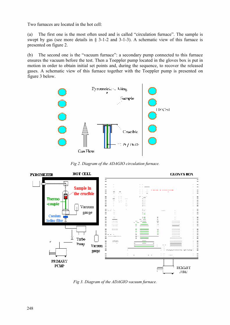
Two furnaces are located in the hot cell:
(a) The first one is the most often used and is called “circulation furnace”. The sample is swept by gas (see more details in § 3-1-2 and 3-1-3). A schematic view of this furnace is presented on figure 2.
(b) The second one is the “vacuum furnace”: a secondary pump connected to this furnace ensures the vacuum before the test. Then a Toeppler pump located in the gloves box is put in motion in order to obtain initial set points and, during the sequence, to recover the released gases. A schematic view of this furnace together with the Toeppler pump is presented on figure 3 below.
Fig 2. Diagram of the ADAGIO circulation furnace.
Fig 3. Diagram of the ADAGIO vacuum furnace.
248
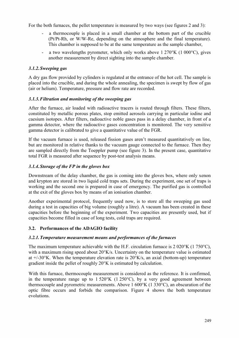
For the both furnaces, the pellet temperature is measured by two ways (see figures 2 and 3):
- a thermocouple is placed in a small chamber at the bottom part of the crucible (Pt/Pt-Rh, or W/W-Re, depending on the atmosphere and the final temperature). This chamber is supposed to be at the same temperature as the sample chamber,
- a two wavelengths pyrometer, which only works above 1 270°K (1 000°C), gives another measurement by direct sighting into the sample chamber.
3.1.2. Sweeping gas
A dry gas flow provided by cylinders is regulated at the entrance of the hot cell. The sample is placed into the crucible, and during the whole annealing, the specimen is swept by flow of gas (air or helium). Temperature, pressure and flow rate are recorded.
3.1.3. Filtration and monitoring of the sweeping gas
After the furnace, air loaded with radioactive tracers is routed through filters. These filters, constituted by metallic porous plates, stop emitted aerosols carrying in particular iodine and caesium isotopes. After filters, radioactive noble gases pass in a delay chamber, in front of a gamma detector, where the radioactive gases concentration is monitored. The very sensitive gamma detector is calibrated to give a quantitative value of the FGR.
If the vacuum furnace is used, released fission gases aren’t measured quantitatively on line, but are monitored in relative thanks to the vacuum gauge connected to the furnace. Then they are sampled directly from the Toeppler pump (see figure 3). In the present case, quantitative total FGR is measured after sequence by post-test analysis means.
3.1.4. Storage of the FP in the gloves box
Downstream of the delay chamber, the gas is coming into the gloves box, where only xenon and krypton are stored in two liquid cold traps sets. During the experiment, one set of traps is working and the second one is prepared in case of emergency. The purified gas is controlled at the exit of the gloves box by means of an ionisation chamber.
Another experimental protocol, frequently used now, is to store all the sweeping gas used during a test in capacities of big volume (roughly a litre). A vacuum has been created in these capacities before the beginning of the experiment. Two capacities are presently used, but if capacities become filled in case of long tests, cold traps are required.
3.2. Performances of the ADAGIO facility
3.2.1. Temperature measurement means and performances of the furnaces
The maximum temperature achievable with the H.F. circulation furnace is 2 020°K (1 750°C), with a maximum rising speed about 20°K/s. Uncertainty on the temperature value is estimated at +/-30°K. When the temperature elevation rate is 20°K/s, an axial (bottom-up) temperature gradient inside the pellet of roughly 20°K is estimated by calculation.
With this furnace, thermocouple measurement is considered as the reference. It is confirmed, in the temperature range up to 1 520°K (1 250°C), by a very good agreement between thermocouple and pyrometric measurements. Above 1 600°K (1 330°C), an obscuration of the optic fibre occurs and forbids the comparison. Figure 4 shows the both temperature evolutions.
249
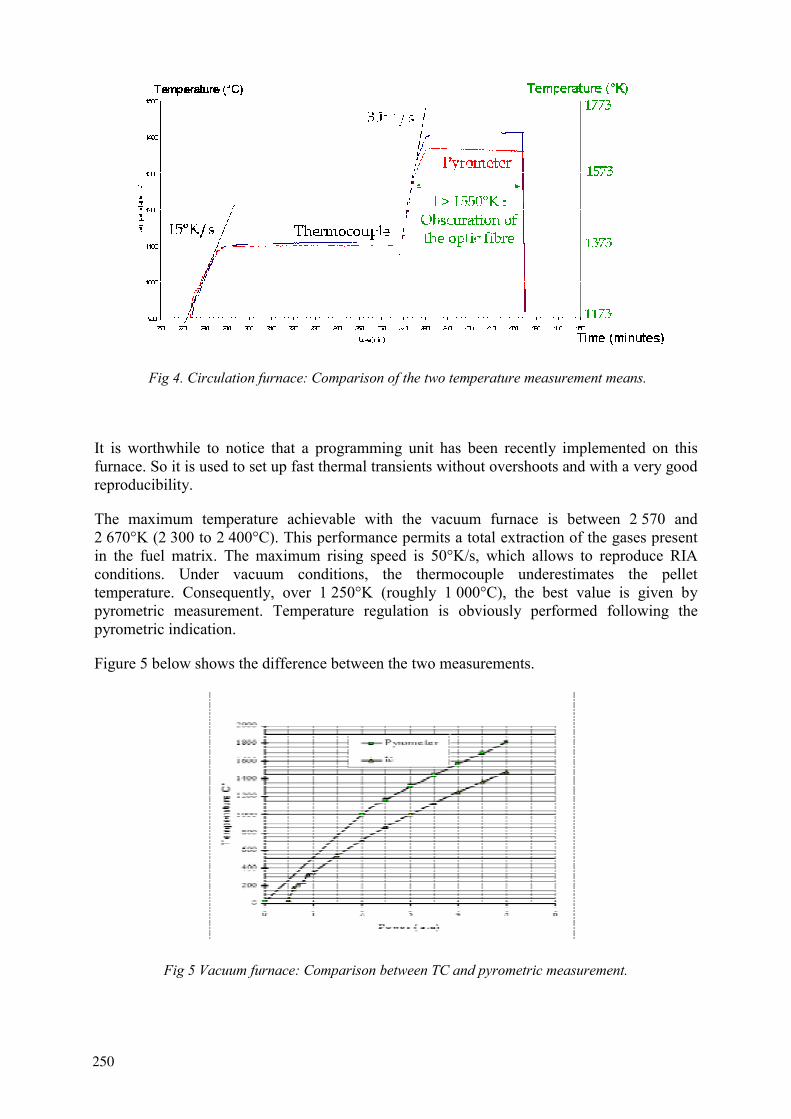
Fig 4. Circulation furnace: Comparison of the two temperature measurement means.
It is worthwhile to notice that a programming unit has been recently implemented on this furnace. So it is used to set up fast thermal transients without overshoots and with a very good reproducibility.
The maximum temperature achievable with the vacuum furnace is between 2 570 and 2 670°K (2 300 to 2 400°C). This performance permits a total extraction of the gases present in the fuel matrix. The maximum rising speed is 50°K/s, which allows to reproduce RIA conditions. Under vacuum conditions, the thermocouple underestimates the pellet temperature. Consequently, over 1 250°K (roughly 1 000°C), the best value is given by pyrometric measurement. Temperature regulation is obviously performed following the pyrometric indication.
Figure 5 below shows the difference between the two measurements.
Fig 5 Vacuum furnace: Comparison between TC and pyrometric measurement.
250

3.2.2. Main characteristics of the sweeping gas flow
The circulation furnace permits to control the atmosphere in contact with the fuel, which is an important parameter for FGR measurement. Two compositions of the sweeping gas are available:
- dry air,
- purified He, with less than 0.4 vpm water vapour and less than 0.1 vpm O2.
The flow rate can be adjusted from 0 up to 100 cm3.mn-1.
Quantification of the gas recovered in the vacuum furnace is possible within a range from 1 up to 10 cm3. The accuracy on this value is +/-0.1 cm3.
3.2.3. Performances of the FGR measurement means
An important advantage of the ADAGIO device is to be able to quantify the FGR thanks to three independent measurement means:
(a) The delay chamber and the associated on-line gamma spectrometer are located in a shielded chamber. The crystal is of Ge HP, P type, with a 60% efficiency (see figure 6). These components are designed to detect a FGR minimum cumulated value of 1% for 85Kr and 0.1% for 133Xe, after a test duration of 1 hour carried out on a 200 mg fuel sample at a burn-up of 50 GWd.thm
-1. Calibration of this system is ensured thanks to 133Xe – 85Kr standard gas sources.
When tests are performed after a short decay time since the end of re-irradiation, other isotopes, such as 133mXe (2.2 days of half-life) and 131mXe (11.9 days) are also detectable.
(b) A gamma spectrometry of the capacities ensures a second measurement of the total radioactive FGR. Calibration of this system is ensured thanks to a 152Eu – 133Ba standard liquid source, with auto-absorption calculations. Efficiency curve is completed with points coming from a second calibration with a 133Xe – 85Kr standard gas source.
A comparison with the on-line gamma spectrometry analysis results permits to confirm the correct calibration of the both devices.
(c) A gas chromatography coupled to a quadrupolar mass spectrometer (GC-MS) permits to measure stable FGR and isotopic composition of stable noble gases. Minimum concentrations of Krypton and Xenon in the carrier gas are 0.15 and 0.07 vpm respectively. Figure 7 gives more details on this device.
Main interest of this method is to be able to measure the fractional release of each stable isotope, whereas gamma spectrometry quantifies FGR only for 85Kr and 133Xe.
Post-tests measurements means developed in points (b) and (c) belong to the MAGALI device, installed in a hot cell of the LAMA Laboratory.
251

Fig. 6 Diagram of the on-line quantitative gamma spectrometry.
Fig. 7 Main characteristics of the MAGALI GC-MS device.
4. ANALYTICAL EXPERIMENTS CARRIED OUT IN THE ADAGIO FACILITY
4.1. LOCA type experiments
4.1.1. Example of thermal time history
A typical example of analytical programme implemented in the circulation furnace of the ADAGIO facility begun at the end of the year 2000, and will be completed in 2002. It concerns the measurement of radioactive and stable noble gases release out of UO2 and MOX pellets, which have been extracted from PWR rods pre-irradiated in power reactors. Each rod section (a pellet with its clad) is tested during a LOCA type sequence.
252
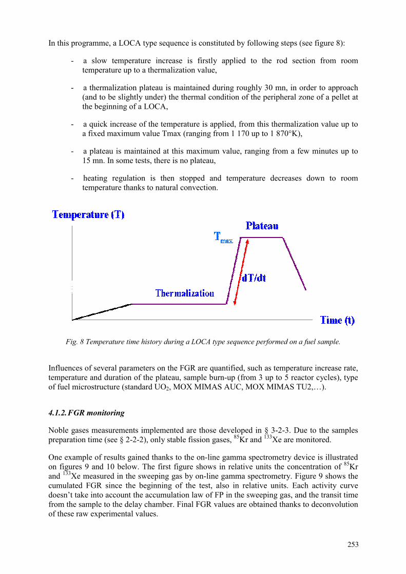
In this programme, a LOCA type sequence is constituted by following steps (see figure 8):
- a slow temperature increase is firstly applied to the rod section from room temperature up to a thermalization value,
- a thermalization plateau is maintained during roughly 30 mn, in order to approach (and to be slightly under) the thermal condition of the peripheral zone of a pellet at the beginning of a LOCA,
- a quick increase of the temperature is applied, from this thermalization value up to a fixed maximum value Tmax (ranging from 1 170 up to 1 870°K),
- a plateau is maintained at this maximum value, ranging from a few minutes up to 15 mn. In some tests, there is no plateau,
- heating regulation is then stopped and temperature decreases down to room temperature thanks to natural convection.
Fig. 8 Temperature time history during a LOCA type sequence performed on a fuel sample.
Influences of several parameters on the FGR are quantified, such as temperature increase rate, temperature and duration of the plateau, sample burn-up (from 3 up to 5 reactor cycles), type of fuel microstructure (standard UO2, MOX MIMAS AUC, MOX MIMAS TU2,…).
4.1.2. FGR monitoring
Noble gases measurements implemented are those developed in § 3-2-3. Due to the samples preparation time (see § 2-2-2), only stable fission gases, 85Kr and 133Xe are monitored.
One example of results gained thanks to the on-line gamma spectrometry device is illustrated on figures 9 and 10 below. The first figure shows in relative units the concentration of 85Krand 133Xe measured in the sweeping gas by on-line gamma spectrometry. Figure 9 shows the cumulated FGR since the beginning of the test, also in relative units. Each activity curve doesn’t take into account the accumulation law of FP in the sweeping gas, and the transit time from the sample to the delay chamber. Final FGR values are obtained thanks to deconvolution of these raw experimental values.
253
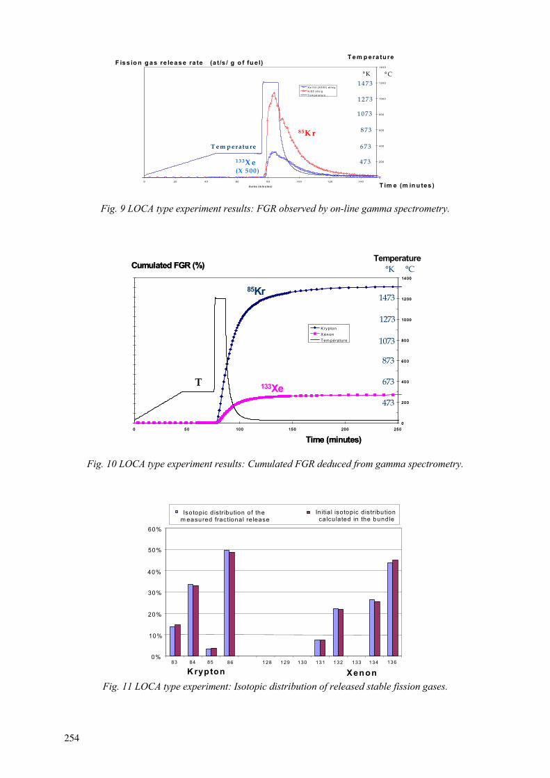
0 2 0 4 0 6 0 8 0 1 0 0 1 2 0 1 4 0
d u ré e (m in u tes )
0
20 0
40 0
60 0
80 0
10 0 0
12 0 0
14 0 0
X e 13 3 (X 5 0 0 ) a t/s /gK r85 a t/s /gT em p é ra ture
F is s io n g a s re le a s e ra te (a t/s / g o f fu e l)
T im e (m in u tes )
T e m p e ra tu re
13 3X e(X 5 0 0 )
8 5K r
T e m p e ra tu re
°C°K
473
873
1273
673
1073
1473
Fig. 9 LOCA type experiment results: FGR observed by on-line gamma spectrometry.
0%
1%
2%
3%
4%
5%
6%
7%
8%
9%
0%
1%
2%
3%
4%
5%
0 5 0 10 0 15 0 20 0 25 0
d u rée (m in u te s)
0
20 0
40 0
60 0
80 0
10 00
12 00
14 00
K ryptonX én onT em pérature
Cumulated FGR (%)
Time (minutes)
0%
1%
2%
3%
4%
5%
6%
7%
8%
9%
0%
1%
2%
3%
4%
5%
0 5 0 10 0 15 0 20 0 25 0
d u rée (m in u te s)
0
20 0
40 0
60 0
80 0
10 00
12 00
14 00
K ryptonX én onT em pérature
Cumulated FGR (%)
Time (minutes)
Temperature
85Kr
133XeT
°C°K
473
673
873
1073
1273
1473
Fig. 10 LOCA type experiment results: Cumulated FGR deduced from gamma spectrometry.
0%
10%
20%
30%
40%
50%
60%
83 84 85 86 128 129 130 131 132 133 134 136
Isotopic d is tribution of the m easured fractional re lease
In itia l isotopic dis tribution calculated in the bundle
K rypton XenonFig. 11 LOCA type experiment: Isotopic distribution of released stable fission gases.
254

Figure 11 shows the isotopic relative distribution of the stable nobles gases Xe and Kr obtained by post-test analyses by mass spectrometry (component of the MAGALI device). Comparison with the same distribution calculated in the fuel matrix indicates a very good relative agreement between calculated and measured values. This validates indirectly calculation of isotopic composition of the sample at the beginning of the re-irradiation, and consequently the radioactive isotopes inventory at the beginning of the test.
0
0.2
0.4
0.6
0.8
1.0
1.2
Kr 83 Kr 84 Kr 85 Kr 86 Xe 131 Xe 132 Xe 133 Xe 134 Xe 136
Krypton XenonFig. 12 LOCA type experiment: Relative fractional release of stable fission gases.
Figure 12 shows the relative fractional release for each Xe and Kr stable isotope, with normalization, for each noble gas, to the isotope that has presented the highest fractional release. It is clearly visible that all measured fractional release values are very similar, and this observation reinforces the reliability of the final stable FGR obtained for such sample.
4.2. Fast transients type experiments
Figure 13 shows a typical thermal time history of a sample tested in the vacuum furnace. Temperature increase rate is very high, above 50°K/s. Such increase rate permits to reach 1 670°K in the sample from room temperature, after roughly 30 s.
0
200
400
600
800
1000
1200
1400
1600
00:10 00:20 00:30 00:40 00:50 01:00
tim e (m inute s:se conds)
Tem
pera
ture
0.000
0.010
0.020
0.030
0.040
0.050
0.060
0.070
0.080
0.090
Pre
ssio
n (m
bar)
pyrometer
vaccum gauge
53°C/s
Fig. 13 Fast transient type experiment: Example of results obtained with the vacuum furnace.
255
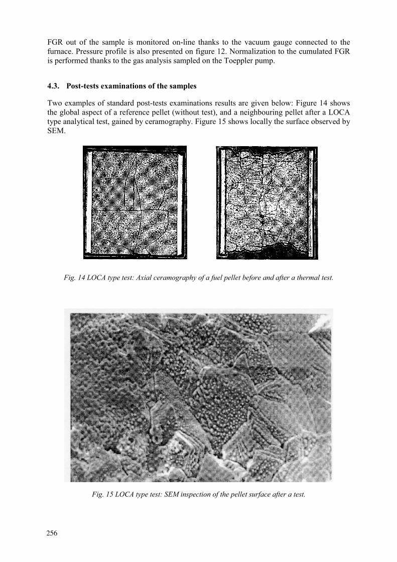
FGR out of the sample is monitored on-line thanks to the vacuum gauge connected to the furnace. Pressure profile is also presented on figure 12. Normalization to the cumulated FGR is performed thanks to the gas analysis sampled on the Toeppler pump.
4.3. Post-tests examinations of the samples
Two examples of standard post-tests examinations results are given below: Figure 14 shows the global aspect of a reference pellet (without test), and a neighbouring pellet after a LOCA type analytical test, gained by ceramography. Figure 15 shows locally the surface observed by SEM.
Fig. 14 LOCA type test: Axial ceramography of a fuel pellet before and after a thermal test.
Fig. 15 LOCA type test: SEM inspection of the pellet surface after a test.
256
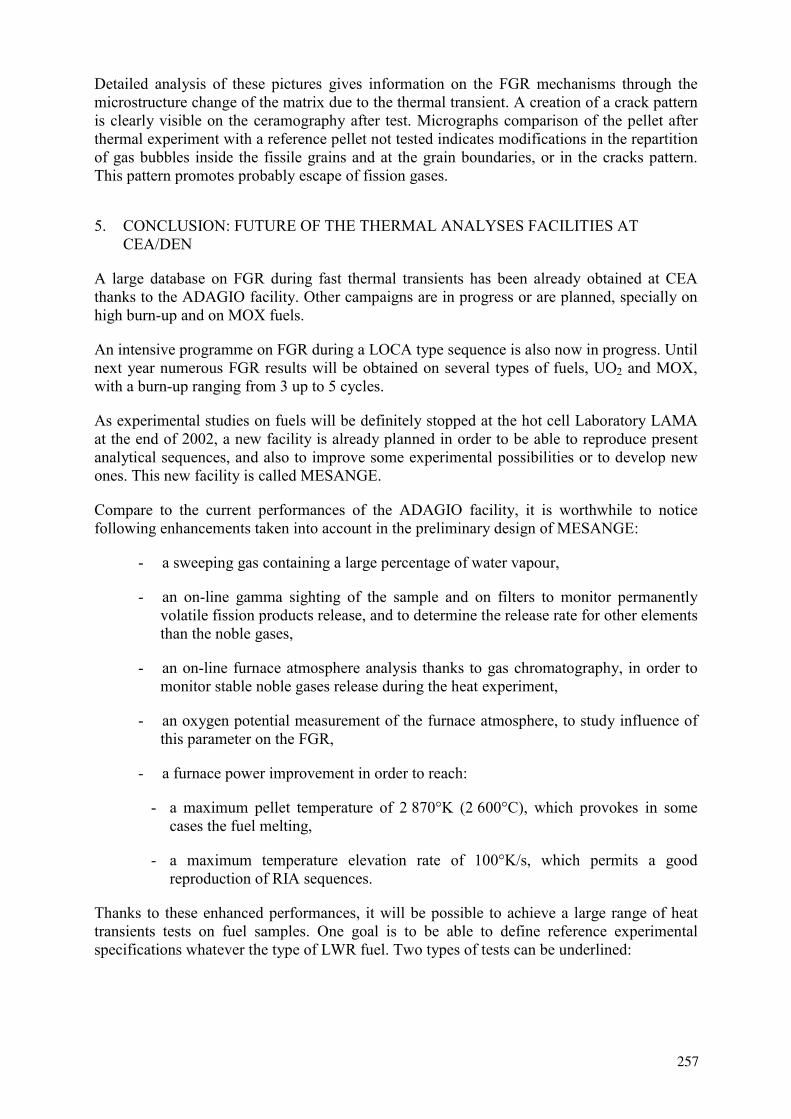
Detailed analysis of these pictures gives information on the FGR mechanisms through the microstructure change of the matrix due to the thermal transient. A creation of a crack pattern is clearly visible on the ceramography after test. Micrographs comparison of the pellet after thermal experiment with a reference pellet not tested indicates modifications in the repartition of gas bubbles inside the fissile grains and at the grain boundaries, or in the cracks pattern. This pattern promotes probably escape of fission gases.
5. CONCLUSION: FUTURE OF THE THERMAL ANALYSES FACILITIES AT CEA/DEN
A large database on FGR during fast thermal transients has been already obtained at CEA thanks to the ADAGIO facility. Other campaigns are in progress or are planned, specially on high burn-up and on MOX fuels.
An intensive programme on FGR during a LOCA type sequence is also now in progress. Until next year numerous FGR results will be obtained on several types of fuels, UO2 and MOX, with a burn-up ranging from 3 up to 5 cycles.
As experimental studies on fuels will be definitely stopped at the hot cell Laboratory LAMA at the end of 2002, a new facility is already planned in order to be able to reproduce present analytical sequences, and also to improve some experimental possibilities or to develop new ones. This new facility is called MESANGE.
Compare to the current performances of the ADAGIO facility, it is worthwhile to notice following enhancements taken into account in the preliminary design of MESANGE:
- a sweeping gas containing a large percentage of water vapour,
- an on-line gamma sighting of the sample and on filters to monitor permanently volatile fission products release, and to determine the release rate for other elements than the noble gases,
- an on-line furnace atmosphere analysis thanks to gas chromatography, in order to monitor stable noble gases release during the heat experiment,
- an oxygen potential measurement of the furnace atmosphere, to study influence of this parameter on the FGR,
- a furnace power improvement in order to reach:
- a maximum pellet temperature of 2 870°K (2 600°C), which provokes in some cases the fuel melting,
- a maximum temperature elevation rate of 100°K/s, which permits a good reproduction of RIA sequences.
Thanks to these enhanced performances, it will be possible to achieve a large range of heat transients tests on fuel samples. One goal is to be able to define reference experimental specifications whatever the type of LWR fuel. Two types of tests can be underlined:
257
- standard tests, to compare performances of current fuels in thermal transients conditions, or to qualify new fuels,
- envelope tests, with envelope conditions compare to those expected in a power reactor, more devoted to safety requirements.
The MESANGE facility is scheduled to be operational at CEA Cadarache, in the hot cell Laboratory LECA, in 2005.
REFERENCES
[1] DUCROS, G., MALGOUYRES, P.P., KISSANE, M., BOULAUD, D., DURIN, M., MAILLIAT, A.,: “Fission product release and fuel behaviour under severe-accidental conditions: synthesis of the VERCORS 1 to 6 experimental program”; International Topical Meeting on LWR Fuel Performance, April, 10-13, 2000, Park City (Utah-USA)
[2] ANDRE, B,. DUCROS, G., LEVEQUE, J.P., MARO, D., OSBORNE, M.F., LORENZ, R.A., Nucl. Technol. 114, (1996), 23.
[3] PONTILLON, Y., MALGOUYRES, P. P., CECCALDI, F., KISSANE, M., BOULAUD, D., DURIN, M.: “Fission-product release and fuel behaviour in severe accident conditions: results of the first VERCORS RT experiments concerning MOX (UO2/PuO2) fuel”; CSARP Annual Review Meeting, 2001, May, 7-9, Washington D.C.
[4] DUCROS, G., FERROUD-PLATTET, M.P., MALGOUYRES, P.P., TOURASSE, M., BOULAUD, D.: "The VERCORS HT program: parametric study of fission product release up to molten core conditions"; CSARP Annual Review Meeting, 1997, May, 5-8, Bethesda
[5] VALIN, S., MOCELLIN, A., EMINET, G., JOUBERT, J.C.: “Modelling the behaviour of intergranular fission gas during out of pile annealing”; International Seminar on Fission Gas Behaviour in Water Reactors Fuels, Cadarache (F), September, 26-29, 2000
[6] NOIROT, L., STRUZIK, C., GARCIA, P., NOIROT, J.: « A mechanistic fission gas behaviour model for UO2 and MOX fuels”; International Seminar on Fission Gas Behaviour in Water Reactors Fuels, Cadarache (F), September, 26-29, 2000
[7] MULLER, E., LEMOINE, F., SAUREL, R.: « A dynamic model for the fission gas induced swelling in high BU fuel under fast power transient »; International Seminar on Fission Gas Behaviour in Water Reactors Fuels, Cadarache (F), September, 26-29, 2000
[8] RAVEL, S., DUCROS, G., PETIT, T., CAILLOT, L., EMINET, G.: “Partition of grain boundary and matrix gas inventories in nuclear fuel: the ADAGIO facility”; European Working Group “Hot Laboratories and Remote Handling” Meeting, Windscale (UK), September, 21-23, 1998
[9] RAVEL, S., MULLER, E., EMINET, G., CAILLOT, L.: « Partition of grain boundary and matrix gas inventories: results obtained with the ADAGIO facility »; International Seminar on Fission gas behaviour in Water Reactors Fuels, Cadarache (F), September, 26-29, 2000
258
A METHODOLOGY FOR THE ESTIMATION OF RELEASE OF FISSION PRODUCTS DURING LOCA WITH LOSS OF ECCS
H.G. LELE, P. MAJUMDAR, D. MUKHOPADHYAY, S.K. GUPTA, V. VENKAT RAJ Health, Safety and Environment Group, Bhabha Atomic Research Centre, Trombay, Mumbai, India
Abstract. A Loss of Coolant Accident (LOCA) in a nuclear reactor along with the failure of the Emergency Core Cooling System can cause sustained voiding of the core. In such a situation the core experiences very low flow which leads to poor heat removal from the reactor core. The heat to be removed from the core includes stored heat, heat generated due to metal water reaction at high temperatures, decay heat etc. The poor heat removal leads to heating of the fuel pins to high temperatures. The heating of fuel pins is further enhanced due to metal-water reaction at high temperatures. These high temperatures of the fuel pins can lead to fission product release, which is transported into the Primary Heat Transport (PHT) system and can enter the containment through the break. Analysis is involved due to the complexity of the system and the phenomena to be simulated. In this paper a multistage analysis methodology is presented that involves the development and application of a number of computer programs to model the various phenomena involved. The computer code PHTACT computes the activity release from the fuel as a function of fuel temperatures and cladding oxidation, its distribution into the PHT system and release into the containment. Computation of thermal hydraulic parameters during LOCA is done using the thermal hydraulic analysis code RELAP5. The detailed simulation of fuel pin temperatures is done using computer code HT/MOD4. The convective boundary conditions required for the code are obtained from RELAP5. Creep deformation is considered in the computation of dimensional changes of the coolant channel and estimation of flow blockage due to clad ballooning. The progression of various reaction layers due to high temperature reaction between fuel and clad and clad and steam is also computed, which affects the structural strength of the clad. Different approaches are possible and analysis can be carried out in different phases depending upon the complexities to be considered. Details of an analysis carried out for the proposed Indian Advanced Heavy Water Reactor (AHWR) and some results are presented in the paper.
1. INTRODUCTION
The proposed Advanced Heavy Water Reactor (AHWR) is a 750 MWth vertical pressure tube type boiling light water cooled and heavy water moderated reactor. One of the important passive design features of this reactor is that the heat removal is achieved through natural circulation of primary coolant at all power level. The present analysis has been carried out to evaluate the thermal-hydraulics of the system and the safety parameters. In this analysis three systems are involved, the Primary Heat Transport (PHT) System, Emergency Core Cooling System (ECCS) and the Isolation Condenser (IC) Circuit which are discussed below,
The Primary Heat Transport System of the proposed AHWR consists of the reactor core, core inlet and core outlet extensions, inlet feeders, tailpipes, steam drums, downcomers and inlet header (Fig. 1). The reactor core consists of 452 Pressure Tubes. In each Pressure Tube, a 54-element single fuel bundle is housed. A displacer rod is placed at the centre of the bundle and the fuel elements are arranged in concentric circles. In the first circle, second circle and third circle 12, 18 and 24 fuel elements are arranged respectively. The coolant leaves the Pressure Tubes with an average exit steam quality of 14% and reaches four steam drums through 452 core top extensions and 452 tail pipes. The steam drum has the large interface area, which provides natural steam separation, without using mechanical separators. At the central location (between two plates) of the steam drum bottom, feed water enters which leads to a
259
subcooled condition after mixing with the saturated water. This subcooled water leaves the steam drums through 16 downcomers to a single ring Inlet Header. From the Inlet Header, the coolant enters the 452 Pressure Tubes through 452 inlet feeders and 452 core bottom extensions.
The reactor has reactor shutdown system for tripping the reactor, relief system for relieving system pressure, isolation condenser for decay heat removal and three stage ECCS.
Analysis is carried out, for the case of a 200 % Reactor Inlet Header break coincident with the failure of ECCS, for predicting the thermal hydraulic behaviour of the different channels considering the power distribution, and fission product release and activity distribution in PHT system. The analysis has been divided into two phases. In the first phase of the analysis, the global thermal hydraulic behaviour of the PHTS is determined using the computer code REALP5 [1]. In the second phase of the analysis, fuel temperatures behaviour from the first phase of analysis are used to obtain fraction of fission product released into different core volumes, while their transport into the PHT system and containment is computed using the thermal hydraulic conditions obtained from phase 1 of the analysis.
This paper presents the postulated scenario, brief description of the codes RELAP5 and PHTACT used for the analysis, modeling of different systems involved in this analysis and the results and discussion on the thermal hydraulic transients and activity released and distribution obtained for LOCA with loss of ECCS. Other methodologies involving slave channel analysis and use of other severe accident analyses codes like HT/MOD4, PTCREEP and SFDCPA are also discussed.
2. DESCRIPTION OF MODELS
Different models as described below can be used in the multistage analysis needed for the computation of fission product release. Analysis can be carried out in number of stages and accordingly appropriate computer codes need to be used. These phases of analyses are described in detail by D. Mukhopadhyay et al. [2]. In this section different codes used for such multistage analysis are described.
2.1. Description of RELAP/MOD3.2.2
The basic field equations for the two-fluid nonequilibium model consist of the two phasic continuity equations, two phasic momentum equations and two phasic energy equations. These equations are formulated in differential stream tube form with time and one space dimension as independent variables and in terms of time and volume-average dependent variables.
The heat structure is assumed to be represented by one-dimensional heat conduction in rectangular, cylindrical, or spherical geometry. Finite difference formulation is used to advance the heat conduction solutions. The heat transfer correlation package can be used for heat structure surface connected to hydrodynamic volumes and contains correlations for convective, nucleate boiling, transition boiling and film boiling heat transfer from the wall to water and reverse transfer from water to wall, including condensation.
260
2.2. Description of HT/MOD4
The reactor channel is simulated thermally in detail. Each fuel pin of the fifty four rod cluster is simulated using a 3-D conduction model with temperature dependent thermal conductivity. The pressure tube and calandria tube are also separately simulated by the 3-D model. Convective and radiative heat transfer serve as the boundary conditions. For determining radiative heat exchange between different nodes a radiosity approach is followed. The deformation of pressure tube and fuel bundles is simulated thermally. References 3 to 5 give detailed description of the code HT/MOD4.
2.3. Description of PHTACT
The analytical model comprises of two parts. The first part computes releases from different locations in the fuel channels into the PHT system, while the second part involves transportation into PHT system and containment. The release models are empirical and are based on NUREG-0772 (U.S. Nuclear, 1981) [6] fission release model and PHTACT code is validated against experimental data of Prussin et al., Johnson et al. etc [7] for its release predictions. Further details of the code are given below:
2.3.1. Fuel Release Model
The core is represented by a number of channels of different ratings, their axial nodes and a number of nodes at each axial location. Modeling of number of rod at each axial location enables the code to simulate different rods in the fuel rod cluster and channel specific phenomena. The code can simulate 20 channels, 20 axial nodes in each channel and 60 rods at each axial location. This results in simulation of a maximum of 24 000 points. The code requires values of initial inventory of species to be released by the core during simulation. Fission product species are distributed among the core nodes according to power peaking factor which is given as input.
At each time step the code requires the current temperature of each node. Based upon the current temperature read, current inventory of the species at the node and appropriate coefficient stored in the core, the fraction of species released during the time step is calculated.
Three separate mechanisms, viz. gap release, temperature dependent release and oxidation enhanced release are used in PHTACT depending on the species and the temperature.
2.3.2. Model to Transport Activity in the PHT System
Various assumptions made in the model are as follows:
1) Activity coming into PHTS is soluble in water. 2) There is no deposition on the PHTS wall. 3) Source due to radioactive decay of fission products is negligible due to their large half
lives.
261

This model computes the activity due to different radioactive species at different locations and time intervals in the PHT system during an accident. Release into the containment is computed by integrating the release out of the break.
Using the above models, the computer code PHTACT is developed. The code can simulate channels of different power ratings, axial power distribution in each channel and rod temperatures at each axial locations. It needs as input initial fission products inventory or activity, their distribution in terms of distribution factors at different locations and radioactive decay constants of different radioactive species. It also needs thermal hydraulic details like number of control volumes, their inter-connections, number of junctions, number of heat generating volumes, number of break volumes and connection of fuel channels to different control volumes. Time dependent inputs for mass inventory in different control volumes, junction flow rates and fuel temperature at each node need to be specified. The computer code checks for total activity conservation at each time step. The code can simulate up to 100 control volumes, 100 junctions and 20 radioactive species.
2.4. Description of PTC
Certain accidental condition in a nuclear reactor would cause the Pressure Tube (PT) temperature to rise significantly due to fuel heat up. This transient causes metallurgical and geometrical changes in PT. At high temperature PT deforms plastically due to internal pressure and fuel weight. Both ballooning and sagging behavior is observed in the PT for horizontal orientation. A model is being developed to simulate the simultaneous deformation behavior and incorporated in a computer program ‘PTC’ (Pressure Tube Creep) [8]. The program 'PTC' predicts the deflection and the strain experienced by the Pressure Tube for both horizontal and vertical orientation. It also predicts the strain for a non-uniform temperature condition of the pressure tube. Creep due to Ballooning and Sagging are metallurgically different phenomena. The coupling between the two creep deformations and the consequent deflection of the pressure tube during the temperature transient had been carried out if situation demands. At high pressure and temperature, the PT deforms primarily outward. Increase in the PT diameter is obtained from the transverse strain rate correlation, which is basically a function of time, temperature and stress. This change in the section modulus of PT affects its deflection behavior at low pressure. Deflection at each section is computed from the elastic strain and local longitudinal creep strain.
2.5. Description of SFDCPA
At high temperature, Zircaloy clad interacts with the UO2 fuel as well as with the steam. This interaction produces compositional as well as geometrical changes in the fuel. Both external and internal oxidation is primarily oxygen diffusion controlled and can result in a maximum of seven distinct layers with different compositions/structures. Primarily, the oxide layers -Zr(O) and ZrO2 significantly reduce the structural strength of the clad. It also contains a low melting eutectic (U-Zr, m.p – 1 150 oC) layer. This layer along with the molten un-oxidized -Zr if present would initiate the dissolution of UO2 and ZrO2. A model has been developed for simulating the interaction and predicts the pellet state before the dissolution process. The model is implemented in the development of a computer code ‘SFDCPA/MOD1’[9]. For any accidental transient condition, the code predicts the growth of the layers and the dimensional changes in the clad due to oxide layer formation. The model solves the diffusion equation for the layers to obtain the oxygen distribution and at the layer interfaces the oxygen gradient in
262

the adjacent layer governs the growth of a layer. The governing equations are formulated into implicit finite difference linearised equations with the layer boundaries moving with time. The uranium and zirconium diffusion within the layers is neglected. The code is applicable for the temperature range 850oC to 1 750oC. It is well validated with experimental data in literature for both isothermal and transient temperature condition.
3. RELAP5/MOD3.2 SPECIFIC AHWR MODELING
Descretisation scheme used for the analysis comprises of 189 volumes, 217 junctions and 20 heat slabs, simulating the reactor coolant loop including the reactor core, core top and bottom extensions, inlet feeders, tail pipes, steam drums, downcomers and inlet header. The nodalisation scheme is depicted in Fig.2. Simulation of different systems and components, channel powers and their axial distribution, phenomena involved in natural circulation reactor and different transients to be considered are some important considerations in discretising the system.
4. RESULTS AND DISCUSSIONS
Figs. 3 to 6 indicate the transient reactor power, pressure at inlet of hot channel, break flow and channel inlet quality representative of the behaviour of the system. As seen from Fig. 3 reactor power comes to decay power level following reactor trip after 1 second. Fig. 4 indicates that system depressurises in about 100 seconds. Break flow accelerates after initiation of break to about 25 000 kg/s and reduces to about zero as system pressure falls. Channel quality shows typical oscillatory behaviour under natural circulation condition with depleted inventory as indicated in Fig. 6.
Figs. 7 to 9 show some of the parameters used as boundary conditions for activity calculations. Fig. 7 indicates hot channel flow behaviour. The flow reverses after initiation of break, oscillates and reaches to about zero towards the end of the transient. Fig. 8 shows mass inventory in the exit volume of hot channel. It oscillates due to flow oscillations in the channel reaching to about zero towards the end. Clad surface temperatures in the hot channel at inlet and exit and at the exit of the average rated channel are depicted in Fig. 9. It is observed that temperature behaviour depends upon axial and radial location and rising trend continues after occurance of critical heat flux as heat transfer to pressure tube, calandria tube and cold moderator is not considered in this analysis.
Various species considered in the analysis of release during the postulated accident are Cesium, Iodine, Krypton, Xenon, Tellurium, Antimony, Barium, Strontium, La, Sn, Silver, Zirconium, Mo and ruthium. They have got different isotopes with different half-lives. Initial data for these species is assumed to be that of Indian Pressurised Heavy Water Reactor for the present study.
Figs. 10 to 15 depict fuel release, containment release, PHT system content and content in hot channel and header volume for Iodine. Out of 1 095 grams of initial inventory in the fuel about 14 grams is released from fuel at around 1500 Seconds. Most of the fuel release goes into containment as seen from Fig. 11. Content in the PHT system depends upon flows, inventory of the control volume and release from fuel as seen from Figs. 12 to 14.
263
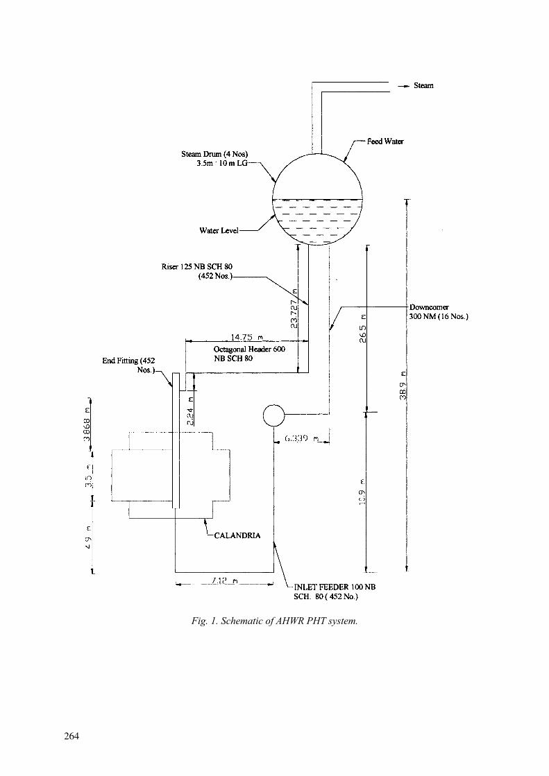
Fig. 1. Schematic of AHWR PHT system.
264
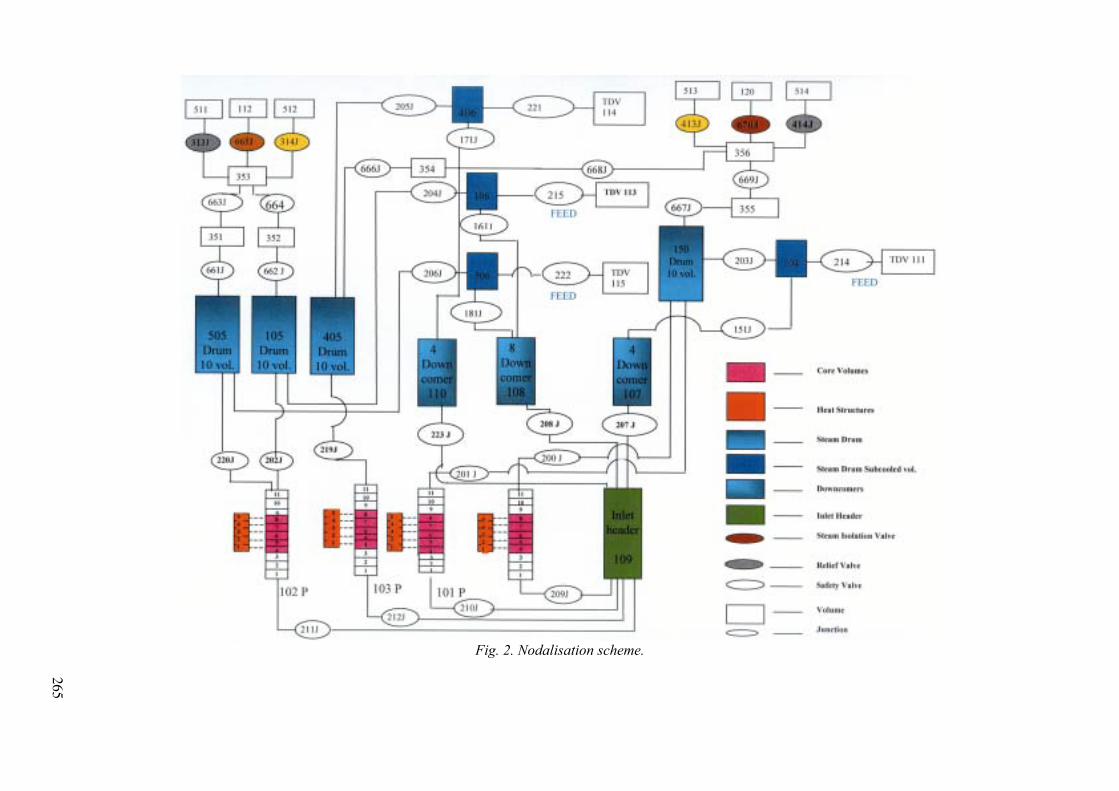
Fig. 2. Nodalisation scheme.
265

266
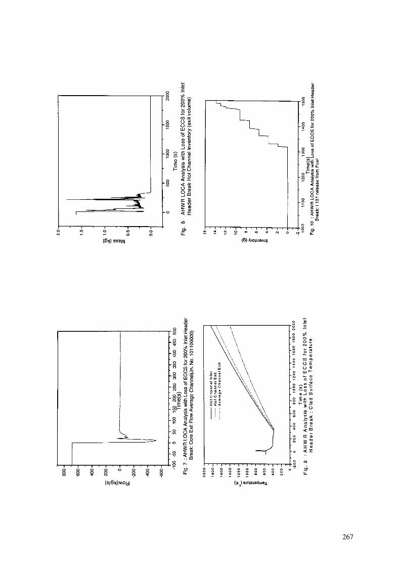
267
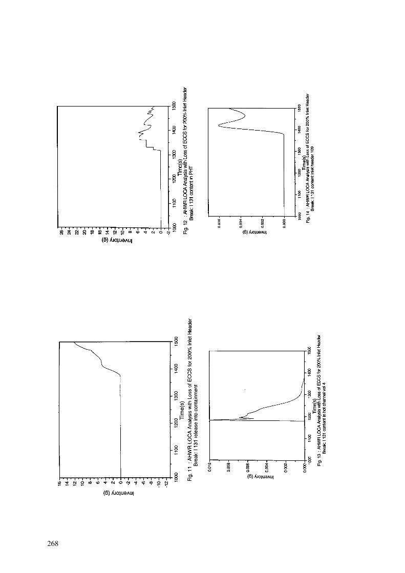
268
5. CONCLUSION
Response of different thermal hydraulic parameters during LOCA with loss of ECCS for the proposed Indian AHWR has been obtained. Using these parameters preliminary estimate of fraction of inventory released into PHT system, its distribution into PHT and release into containment is estimated. Further refined computations need to be done to account for different methodology like slave channel analysis and different phenomena like radiation heat transfer between rods, pressure tube creep, different zirconium reactions with UO2 and steam, dimensional changes in the fuel rods etc.
REFERENCES
[1] FLETCHER, C.D., SCHULTZ, R.R., “RELAP5/MOD3 code manual”, June 1995, Idaho National Engineering Laboratory, Idaho Falls, Idaho.
[2] MUKHOPADHYAY, H.G.LELE, D., GUPTA S.K., and VENKAT, V.R., “Behaviour of an Indian Pressurised Heavy Water Reactor Fuel Channel during a Large LOCA Coincidence with the Failure of ECCS – New Approach”, Paper No. AJTE99/6207, Proceedings of the 5th ASME/JSME Joint Thermal Engineering Conference, March 1999, San Diego, California, USA.
[3] GUPTA S.K., , “Thermal Transients in Horizontal Reactor Channel of a Pressurised Heavy Water Reactor Under Loss of Coolant Accident Conditions”, Ph.D. thesis, Indian Institute of Technology, Bombay, 1991, India.
[4] GUPTA, S.K., DUTTA, B.K., VENKAT, V.R. and KAKODKAR, A., , “A Study of Indian PHWR Reactor Channel Under Prolonged Deteriorated Flow Conditions”, IAEA TCM on Advances in Heavy Water Reactors, Bombay, 29th Jan-1st Feb 1996.
[5] GUPTA S.K., VENKAT RAJ V. and KAKODKAR A., “Predictions for a Severe Accident in an Indian PHWR using Computer Code HT/MOD4, TCM in Advances in AMI experience with Accident Consequences Analysis” Vienna 27-29 September 1995.
[6] KUHLMAN M.R., LEHMICKE D.J., “CORSOR : User’s Manual”, NUREG/CR/-4173, 1985.
[7] LELE, H.G., MUKHOPADHYAY, D., BEHRA, G. and GUPTA, S.K., “ PHTACT- A Computer Code for Fission Product Release and Transport for Pressurised Water Reactor during Accident Conditions, RSD/CSSS/SKG/2069/2001, Divisional Report, April 2001.
[8] MAJUMDAR, P., MUKHOPADHYAY, D. and GUPTA, S.K., “Development of Computer Program to Simulate Pressure Tube Balooning during LOCA Transients.”, RSD/CSSS/SKG/2069/2001, Divisional Report, June 1999.
[9] MAJUMDAR, P., MUKHOPADHYAY, D. and.GUPTA, S.K, “UO2-Zr Chemical Interaction of PHWR Fuel Pins under High Temperature”, 9th Int. Conference on Nuclear Engineering, USA, 2000,
269

STUDY ON HIGH BURNUP FUEL BEHAVIOURUNDER A LOCA CONDITION AT JAERI
F. NAGASE, M. TANIMOTO, H. UETSUKA Department of Reactor Safety Research, Japan Atomic Energy Research Institute, Japan
Abstract. A systematic research program is being conducted at the Japan Atomic Energy Research Institute (JAERI) with a view to obtaining basic data to evaluate high burnup fuel rod behavior under a loss-of-coolant accident (LOCA) condition. In the program, “integral thermal shock tests” are being performed to evaluate the failure-bearing capability of oxidized cladding under simulated-LOCA conditions. Results from the tests performed with non-irradiated Zircaloy-4 cladding tubes are described in the present paper. The cladding tubes were mechanically thinned and pre-hydrided to simulate corrosion and hydrogen absorption of high burnup fuel cladding. About 10% reduction of initial cladding thickness and a hydrogen concentration of 100 to 1 200wtppm were adopted. A short test rod with the pre-hydrided cladding tube was isothermally oxidized at 1 273 through 1 523 K for 30 to 5 500s after rod-burst, and was quenched by flooding water. The test rod was axially restrained during quench to simulate possible restriction of the cladding shrinkage with the temperature decrease. In addition to fully restrained condition, tensile load generated on the test rod was controlled and limited to three different levels of about 390, 540, and 735N to realize intermediate restraint conditions. As a result, variations of the failure threshold value were evaluated as functions of hydrogen concentration and restrained condition. The failure threshold generally decreased with the increase of tensile load. The influence of pre-hydriding was obviously seen on the failure threshold under restraint conditions. Consequently, the threshold of highly pre-hydrided cladding tubes was as low as 10% ECR under the fully restrained condition which is the most conservative loading condition. On the other hand, it was estimated to be higher than 20% ECR when the tensile load was controlled below about 600N, for the hydrogen concentration range that was examined.
1. INTRODUCTION
For the better fuel cycle economy, the maximum fuel burnup has been extended to higher levels in many countries. Though the maximum discharge burnup of fuel assembly is currently limited to 55GWd/t for BWRs and 48GWd/t for PWRs, respectively, in Japan, the research and development have been extensively conducted by industries aiming at higher levels of burnup. With the burnup extension, various changes occur in a fuel rod and they might reduce the margin of fuel reliability and safety. Waterside corrosion and accompanied hydrogen absorption as well as irradiation damage become significant in the Zircaloy cladding tube, besides FP gas accumulation in fuel pellets and chemical bonding between pellet and cladding tube progresses at the high burnup. These phenomena could influence the fuel behavior under a loss-of-coolant accident (LOCA) condition. In particular, degradation of cladding mechanical property due to corrosion and hydrogen pickup is considered the key factor influencing the integrity of fuel rod under a LOCA.
The Japanese LOCA criteria on fuel safety, 15% ECR and 1 200 oC peak cladding temperature, were established in 1975 and it was based on the concept of zero ductility of cladding as in the U.S. After their establishment, the Japan Atomic Energy Research Institute
ECR: Equivalent Cladding Reacted (Proportion of oxide layer thickness assuming that all of absorbed oxygen forms stoichiometric ZrO2).
270
(JAERI) found that inner surface oxidation of the cladding after rod-burst is accompanied by significant hydrogen absorption [1]. Ring compression tests were performed on the cladding specimen that experienced rod-burst and double-sided oxidation in order to examine the embrittlement of the cladding due to oxidation and hydrogen absorption. The ring specimens failed at several %ECR, indicating that the significant hydrogen absorption enhances cladding embrittlement [2]. Accordingly, JAERI conducted “integral thermal shock tests” to evaluate the failure-bearing capability of oxidized cladding under appropriately simulated-LOCA conditions [3]. In the test, a short test rod was heated up, burst, oxidized in steam and quenched by flooding water. During a LOCA transient a fuel rod shall axially expand with the temperature increase, while it shall shrink with the temperature decrease. Oxide formation and growth on the cladding surface might enhance the fuel rod expansion. In the bundle geometry, the shrinkage of fuel rod could be restricted to some extent between grid positions due to possible mechanisms, though the extent is greatly dependent on the fuel assembly design. Then, the tests have been conducted under fully restrained condition to conservatively simulate the possible occurrence of tensile loads on a fuel rod. Obtained results confirmed that the criteria of 15% cladding oxidation still have safety margin, and the LOCA criteria were revised in 1981 referring the results of the integral thermal shock tests. Therefore, the current Japanese LOCA criteria on fuel safety are not based on the concept of zero ductility of cladding, but on the failure threshold value determined in the integral thermal shock tests under the fully restrained condition.
The current LOCA criteria are generally based on the database which were obtained from tests with non-irradiated cladding (as-received) tubes. Although burnup effect was generally taken into account for the revised criteria, the level of fuel burnup was rather low at that time. High burnup fuel behavior under a LOCA condition is a subject of great concern not only in Japan but also in many countries; consequently, extensive research programs have been performed in France, the Unites States and Japan etc. [5-10]. A systematic research program is being conducted at JAERI with a view to obtaining a wide range database for evaluating the influence of burnup extension on fuel behavior under LOCA conditions. Since the integral thermal shock tests are essential to evaluating the safety of the high burnup fuel as described above, the tests are being conducted for evaluating the failure-bearing capability of the high burnup fuel cladding. The outline of the research program and recent results from the tests are described in the present paper.
2. OUTLINE OF PROGRAM
The research program consists of integral thermal shock tests and other separate tests including Zircaloy-steam oxidation tests, mechanical property tests of cladding, and tube burst tests. Several types of Zircaloy cladding samples are used for these tests to assess separate effects and to provide a wide range of basic data available for regulatory judgment. They are (a) as-received cladding tube, (b) simulated high burnup fuel cladding that is artificially pre-oxidized, pre-hydrided and/or neutron irradiated, and (c) high burnup PWR fuel cladding [4]. The schedule of present research program is shown in Table 1. The integral thermal shock tests, the oxidation tests, the mechanical tests have been performed with non-irradiated cladding tubes so far. Preparations for the tests with irradiated cladding tubes are progressed in parallel. As a part of the program, a computer code is developed to analyze the fuel rod behavior under LOCA conditions including possible cladding failure on quenching. Data from the experiments will be incorporated into the computer code. The program will be once summarized in five years, then the tests will be continued targeting at the higher burnup range
271

in the long-term research program of JAERI, Advanced LWR Fuel Performance and Safety Research Program (ALPS Program). High burnup UO2 and MOX fuels will be shipped from European countries to JAERI, and subjected to the systematic fuel safety research, such as the NSRR tests and the LOCA experiments. In addition, a part of the fuels will be subjected to additional irradiation for further burnup accumulation.
TABLE I. SCHEDULE OF RESEARCH PROGRAM ON HIGH BURNUP FUEL BEHAVIOUR UNDER LOCA CONDITIONS
1999 2000 2001 2002 2003 2004 2005F.Y.
Non-irradiated Irradiated
Non-irradiated Irradiated
Non-irradiatedIrradiated
IrradiatedNon-irradiated
Integral thermal shock test
Oxidation test
Burst test
Mechanical test
Fuel relocation
Codedevelopment
Irradiated
Higher burnupin ALPS
1999 2000 2001 2002 2003 2004 2005F.Y.
Non-irradiated Irradiated
Non-irradiated Irradiated
Non-irradiatedIrradiated
IrradiatedNon-irradiated
Integral thermal shock test
Oxidation test
Burst test
Mechanical test
Fuel relocation
Codedevelopment
Irradiated
Higher burnupin ALPS Higher burnupin ALPS
3. INTEGRAL THERMAL SHOCK TESTS
3.1. Test procedure
Non-irradiated low-tin (1.3wt%Sn) Zircaloy-4 cladding was used in the present study. It was the 17x17-type cladding currently used in the PWRs. The outer and inner diameters of the cladding were 9.50 and 8.36 mm, respectively, and the thickness was 0.57mm. Initial hydrogen concentration was about 10wtppm. Key points for evaluating the failure-bearing capability of the high burnup fuel cladding are considered to be;
- Degradation of cladding ductility due to reduction of cladding wall thickness by waterside corrosion, hydrogen absorption, and neutron irradiation, and
- Axial constraint condition.
Considering the first point, the cladding tubes were mechanically thinned from the outer surface and pre-hydrided to simulate corrosion and hydrogen absorption of high burnup fuel cladding. About 10% reduction of initial cladding thickness and a hydrogen concentration of 100 to 1 200wtppm were adopted in the present study. A short test rod was assembled with 600-mm cladding tube, Alumina pellets, stainless steel end plugs and Swagelok, and was filled with 5 MPa Ar gas at room temperature to rupture the rod with the temperature increase. Schematic drawing of the test apparatus is shown in Fig.1, which is composed of an Instron
272
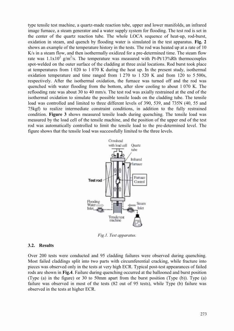
type tensile test machine, a quartz-made reaction tube, upper and lower manifolds, an infrared image furnace, a steam generator and a water supply system for flooding. The test rod is set in the center of the quartz reaction tube. The whole LOCA sequence of heat-up, rod-burst, oxidation in steam, and quench by flooding water is simulated in the test apparatus. Fig. 2shows an example of the temperature history in the tests. The rod was heated up at a rate of 10 K/s in a steam flow, and then isothermally oxidized for a pre-determined time. The steam flow rate was 1.1x10² g/m2/s. The temperature was measured with Pt-Pt/13%Rh thermocouples spot-welded on the outer surface of the cladding at three axial locations. Rod burst took place at temperatures from 1 020 to 1 070 K during the heat up. In the present study, isothermal oxidation temperature and time ranged from 1 270 to 1 520 K and from 120 to 5 500s, respectively. After the isothermal oxidation, the furnace was turned off and the rod was quenched with water flooding from the bottom, after slow cooling to about 1 070 K. The reflooding rate was about 30 to 40 mm/s. The test rod was axially restrained at the end of the isothermal oxidation to simulate the possible tensile loads on the cladding tube. The tensile load was controlled and limited to three different levels of 390, 539, and 735N (40, 55 and 75kgf) to realize intermediate constraint conditions, in addition to the fully restrained condition. Figure 3 shows measured tensile loads during quenching. The tensile load was measured by the load cell of the tensile machine, and the position of the upper end of the test rod was automatically controlled to limit the tensile load to the pre-determined level. The figure shows that the tensile load was successfully limited to the three levels.
Fig.1. Test apparatus.
3.2. Results
Over 200 tests were conducted and 95 cladding failures were observed during quenching. Most failed claddings split into two parts with circumferential cracking, while fracture into pieces was observed only in the tests at very high ECR. Typical post-test appearances of failed rods are shown in Fig.4. Failure during quenching occurred at the ballooned and burst position (Type (a) in the figure) or 30 to 50mm apart from the burst position (Type (b)). Type (a) failure was observed in most of the tests (82 out of 95 tests), while Type (b) failure was observed in the tests at higher ECR.
273
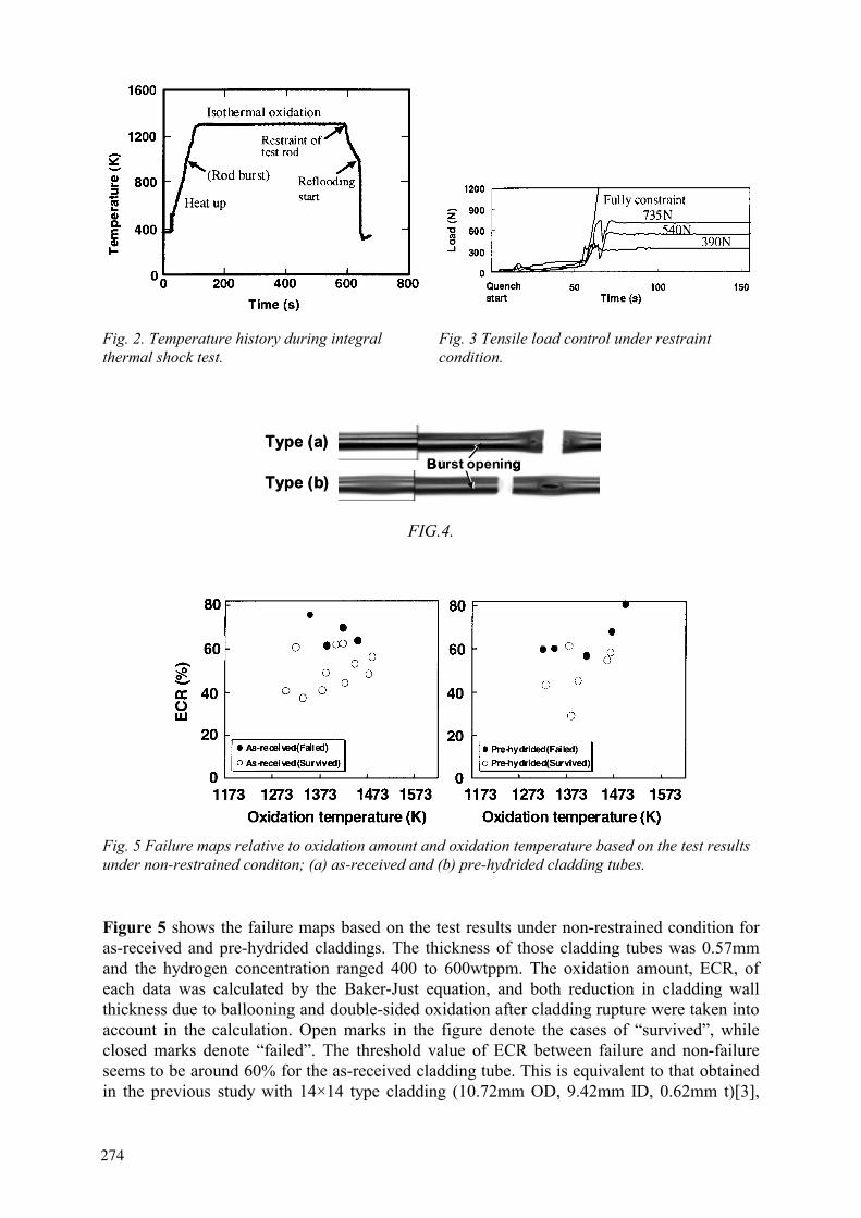
Fig. 2. Temperature history during integral thermal shock test.
Fig. 3 Tensile load control under restraint condition.
Burst openingBurst openingBurst openingType (a)
Type (b)Burst openingBurst openingBurst openingBurst openingBurst openingBurst opening
Type (a)
Type (b)
FIG.4.
Fig. 5 Failure maps relative to oxidation amount and oxidation temperature based on the test results under non-restrained conditon; (a) as-received and (b) pre-hydrided cladding tubes.
Figure 5 shows the failure maps based on the test results under non-restrained condition for as-received and pre-hydrided claddings. The thickness of those cladding tubes was 0.57mm and the hydrogen concentration ranged 400 to 600wtppm. The oxidation amount, ECR, of each data was calculated by the Baker-Just equation, and both reduction in cladding wall thickness due to ballooning and double-sided oxidation after cladding rupture were taken into account in the calculation. Open marks in the figure denote the cases of “survived”, while closed marks denote “failed”. The threshold value of ECR between failure and non-failure seems to be around 60% for the as-received cladding tube. This is equivalent to that obtained in the previous study with 14×14 type cladding (10.72mm OD, 9.42mm ID, 0.62mm t)[3],
274
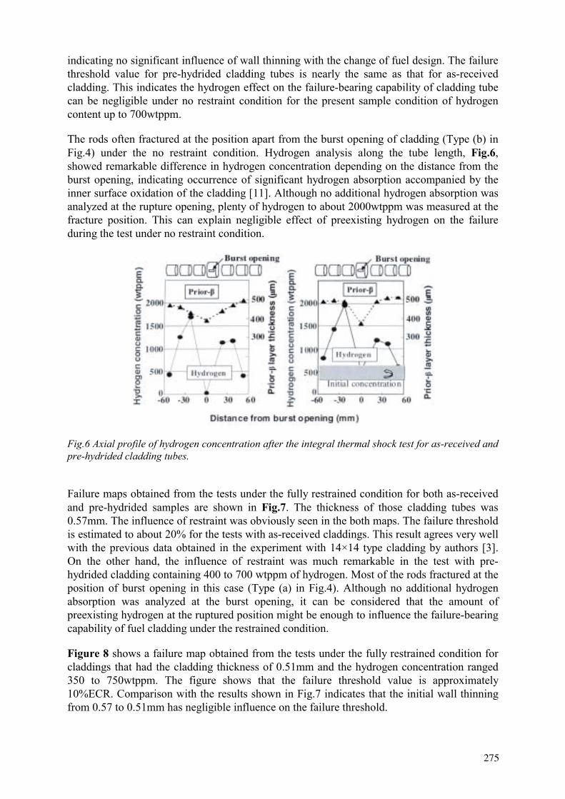
indicating no significant influence of wall thinning with the change of fuel design. The failure threshold value for pre-hydrided cladding tubes is nearly the same as that for as-received cladding. This indicates the hydrogen effect on the failure-bearing capability of cladding tube can be negligible under no restraint condition for the present sample condition of hydrogen content up to 700wtppm.
The rods often fractured at the position apart from the burst opening of cladding (Type (b) in Fig.4) under the no restraint condition. Hydrogen analysis along the tube length, Fig.6,showed remarkable difference in hydrogen concentration depending on the distance from the burst opening, indicating occurrence of significant hydrogen absorption accompanied by the inner surface oxidation of the cladding [11]. Although no additional hydrogen absorption was analyzed at the rupture opening, plenty of hydrogen to about 2000wtppm was measured at the fracture position. This can explain negligible effect of preexisting hydrogen on the failure during the test under no restraint condition.
Fig.6 Axial profile of hydrogen concentration after the integral thermal shock test for as-received and pre-hydrided cladding tubes.
Failure maps obtained from the tests under the fully restrained condition for both as-received and pre-hydrided samples are shown in Fig.7. The thickness of those cladding tubes was 0.57mm. The influence of restraint was obviously seen in the both maps. The failure threshold is estimated to about 20% for the tests with as-received claddings. This result agrees very well with the previous data obtained in the experiment with 14×14 type cladding by authors [3]. On the other hand, the influence of restraint was much remarkable in the test with pre-hydrided cladding containing 400 to 700 wtppm of hydrogen. Most of the rods fractured at the position of burst opening in this case (Type (a) in Fig.4). Although no additional hydrogen absorption was analyzed at the burst opening, it can be considered that the amount of preexisting hydrogen at the ruptured position might be enough to influence the failure-bearing capability of fuel cladding under the restrained condition.
Figure 8 shows a failure map obtained from the tests under the fully restrained condition for claddings that had the cladding thickness of 0.51mm and the hydrogen concentration ranged 350 to 750wtppm. The figure shows that the failure threshold value is approximately 10%ECR. Comparison with the results shown in Fig.7 indicates that the initial wall thinning from 0.57 to 0.51mm has negligible influence on the failure threshold.
275
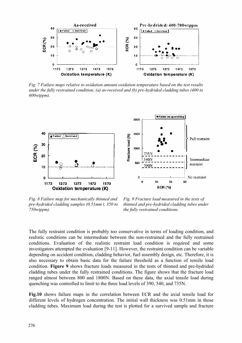
Fig. 7 Failure maps relative to oxidation amount oxidation temperature based on the test results under the fully restrained condition; (a) as-received and (b) pre-hydrided cladding tubes (400 to 600wtppm).
Fig. 8 Failure map for mechanically thinned and pre-hydrided cladding samples (0.51mm t, 350 to 750wtppm).
Fig. 9 Fracture load measured in the tests of thinned and pre-hydrided cladding tubes under the fully restrained conditions.
The fully restraint condition is probably too conservative in terms of loading condition, and realistic conditions can be intermediate between the non-restrained and the fully restrained conditions. Evaluation of the realistic restraint load condition is required and some investigators attempted the evaluation [9-11]. However, the restraint condition can be variable depending on accident condition, cladding behavior, fuel assembly design, etc. Therefore, it is also necessary to obtain basic data for the failure threshold as a function of tensile load condition. Figure 9 shows fracture loads measured in the tests of thinned and pre-hydrided cladding tubes under the fully restrained conditions. The figure shows that the fracture load ranged almost between 800 and 1800N. Based on these data, the axial tensile load during quenching was controlled to limit to the three load levels of 390, 540, and 735N.
Fig.10 shows failure maps in the correlation between ECR and the axial tensile load for different levels of hydrogen concentration. The initial wall thickness was 0.51mm in those cladding tubes. Maximum load during the test is plotted for a survived sample and fracture
276
load is plotted for a failed sample. The figures reveal that the failure threshold generally decreases with the increase of axial tensile load. Increase of hydrogen concentration as well decreases the failure threshold both in the intermediate and the fully restrained conditions. For hydrogen concentrations lower than 750wtppm, the failure threshold remarkably decreased as the axial load decreased to the intermediate range. On the other hand, the threshold is still low at 600N for higher than 750wtppm, and it increased from 10 to 25%ECR with decrease of axial load. Consequently, from the present results, it was estimated to be higher than 20% ECR when the tensile load was controlled below about 600N, for the hydrogen concentration range that was examined.
Fig. 10 Failure maps relative to oxidation amount and axial load based on the test results under the fully restrained and the controlled load conditions; (a) 100 to 350wtppm, (b) 350 to 750wtppm, (c) 750-1 200wtppm.
4. SUMMARY
A systematic research program on high burnup fuel behavior under a LOCA condition is being conducted at JAERI, aiming at a wide range database for evaluating the influence of burnup extension. In the program, the integral thermal shock tests to evaluate the failure-bearing capability of oxidized cladding on quenching were performed with non-irradiated Zircaloy-4 cladding tubes that were pre-hydrided to 1200wtppm. Axial tensile loads generated by restricting the cladding shrinkage are controlled to realize intermediate restraint conditions in addition to the fully restrained condition. As a result, variations of the failure threshold value were evaluated as functions of hydrogen concentration and restrained condition during quenching.
- The failure threshold generally decreased with the increases in axial tensile load. - The influence of pre-hydriding was obviously seen on the failure threshold value under
restraint conditions.- The threshold of highly pre-hydrided claddings was as low as 10% ECR under the fully
restrained condition which is the most conservative loading condition. - It was estimated to be higher than 20% ECR when the axial tensile load was controlled
below 600N, for the hydrogen concentration range that was examined.
ACKNOWLEDGEMENTS
The integral thermal shock tests under controlled tensile loads were carried out as the collaboration program between JAERI and Japanese PWR utilities.
REFERENCES
[1] UETSUKA, H., et al., J. Nucl.Sci.& Tech. Vol.20, No.9, pp.705, 1981. [2] UETSUKA, H. et al., report JAERI-M 9445, April, 1981 (Text in Japanese). [3] UETSUKA, H. et al., J. Nucl.Sci.& Tech., Vol.20, No.11, pp 941, 1983. [4] NAGASE, F. et al., Proceedings of ANS topical meeting on LWR fuel performance, Park
City (USA), April 10-13, 2000. [5] GRANDJEAN, C., et al.,. Proceedings of 24th Water Reactor Safety Information Meeting,
NUREG/CP-0157, Vol.1, October, 1996. [6] WAECKEL, N., et al., ibid.
277
[7] OZAWA, M., et al, Twelfth International Symposium on Zirconium in the Nuclear Industry, 1998.
[8] AOMI, M., et al, Proceeding of ANS topical meeting on LWR fuel performance, Park City (USA), April 10-13, 2000.
[9] HONMA, K., et al., ANS Annual Meeting, Milwaukee, Wisconsin, June 17-21, 2001. [10] MURATA, T., et al., ANS Annual Meeting, Milwaukee, Wisconsin, June 17-21,
2001.WAECKEL, N., et al, OECD/NEA SEG/FSM LOCA Meeting March 22-23, 2001, Aix-en-Province, March, 2001.UETSUKA, H.,et al., J. Nucl. Sci.& Technol., Vol.18, No.9, pp 705-717, 1981.
278
IPSN PROPOSAL FOR HIGH BURNUP FUEL LOCA EXPERIMENTAL PROGRAMS
A. MAILLIAT, C. GRANDJEAN, G. HACHE Institut de Protection et de Sûreté Nucléaire, Département de Recherches en Sécurité, Cadarache, France
Abstract. Safety studies performed in IPSN and elsewhere pointed out that high burn up might induce significant effects, especially those related with fuel relocation during LOCA situations. Uncertainties exist regarding how much the existing safety margins associated with peak clad temperature, clad oxidation, core coolability, clad residual ductility can be reduced by new fuels like the MOX one, burn up increases, the arrival of various alloys for fuel rod cladding. A better knowledge of specific phenomena associated to fuel effects is required in order to estimate the new margins and to resolve the pending uncertainties related to the LOCA criteria. Therefore, in addition to the programmes currently planned in the Halden reactor, IPSN is preparing the so-called “APRP-Irradié” (High Burn up fuel LOCA) programme. One of the important aspects of this programme is In-Pile experiments involving bundle geometries in the PHEBUS facility located at Cadarache, France.
1. INTRODUCTION
In France and in other countries, a permanent evolution of the light water reactors (LWR) is observed since the seventies. The evolution deals with the reactor designs (900 MWe/3 loops, 1300MWe/4 loops, N4, future EPR). It is also related to the fuel management and burnup increase (3 cycles, 4 cycles, 391 GWd/tU, 47, 52, 60 GWd/tU in the next future). This evolution affects the fuel itself (UO2, MOX, Gd fuel), the cladding (Zircaloy, Zirlo, M5) and the control rods (Ag-In-Cd, B4C). As a consequence of these modifications, there is a permanent need to reassess the reactor safety studies which implies improving the associated knowledge and upgrading the corresponding calculation tools. Such a need is not specific to the French situation. For the studies associated with the continuous evolution of the reactor operation, the safety authorities requirements are both related to the design basis accidents and the severe accidents. They have to appreciate to which extent their analyses and criteria might be modified by the burnup increase and the type of fuel. In France, under safety considerations, it was requested prior to any generic authorisation of discharge burn-up extension, that the high burn-up fuel behaviour be validated, with the support of appropriate R&D tests results, under accidental conditions, particularly under Loss-of-Coolant-Accident (LOCA) conditions.
The current regulatory safety criteria for LOCA, still in use in most countries, are derived from the ECCS acceptance criteria that were issued by USAEC in December 1973 and published in the Code of Federal Regulations (10.CFR50, part 50.46) as "Acceptance Criteria for Emergency Core Cooling Systems for Light-Water-Cooled-Nuclear Power Reactors".
1 Mean value per assembly.
279

Fig. 1 Typical LOCA Transient
The criteria are stated as 5 requirements, concerning the calculated performance of the cooling system under the most severe loss-of-coolant accident conditions. A summary of these conditions is given on the figure 1 against. These first two requirements address : the peak cladding temperature (PCT) which shall not exceed 1 204°C and the maximum cladding oxidation rate, defined through an equivalent cladding reacted (ECR), which shall nowhere exceed 17% of the cladding thickness before oxidation but after cladding swelling with or without rupture.
The third request addresses the maximum hydrogen generation, the total amount of which shall not exceed 1% of the hypothetical amount generated by the reaction of all the metal in the cladding surrounding fuel. Finally the last two requirements are related with core cooling. The calculated changes in core geometry shall leave the core amenable to cooling and after any operation of the ECCS, the core temperature shall be maintained at an acceptably low value and decay heat removed for the extended period of time required by long-lived radioactivity.
2. UNCERTAINTIES AND PENDING ISSUES
In the aftermath of the AEC LOCA criteria release, numerous studies were undertaken world-wide in order to improve the basic knowledge of the physical phenomena intervening in LOCA transients, so as to allow a better prediction with realistic models. Beyond the numerous experimental investigations that were conducted on unirradiated rods or cladding, either in-pile or out-of-pile, there exists a few number of available results of such experiments with irradiated material. Following is a very short review of the current knowledge on clad and fuel rod behaviour gained from experiments on irradiated material, that will introduce the pending questions and critical issues for irradiated fuel behaviour in LOCA.
2.1. Uncertainties
2.1.1. Clad Behaviour
An important progress in knowledge relative to irradiated clad behaviour has been obtained from the results of the French EDF/IPSN [1,2] program (TAGCIR and HYDRAZIR tests), addressing the oxidation kinetics and quench bearing capability of irradiated zircaloy. The main outcome concern :
280
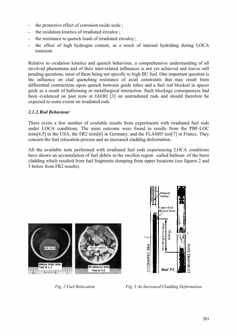
- the protective effect of corrosion oxide scale ; - the oxidation kinetics of irradiated zircaloy ; - the resistance to quench loads of irradiated zircaloy ; - the effect of high hydrogen content, as a result of internal hydriding during LOCA
transient.
Relative to oxidation kinetics and quench behaviour, a comprehensive understanding of all involved phenomena and of their inter-related influences is not yet achieved and leaves still pending questions, most of them being not specific to high BU fuel. One important question is the influence on clad quenching resistance of axial constraints that may result from differential contractions upon quench between guide tubes and a fuel rod blocked in spacer grids as a result of ballooning or metallurgical interaction. Such blockage consequences had been evidenced on past tests at JAERI [3] on unirradiated rods and should therefore be expected to some extent on irradiated rods.
2.1.2. Rod Behaviour
There exists a few number of available results from experiments with irradiated fuel rods under LOCA conditions. The main outcome were found in results from the PBF-LOC tests[4,5] in the USA, the FR2 tests[6] in Germany, and the FLASH5 test[7] in France. They concern the fuel relocation process and an increased cladding deformation.
All the available tests performed with irradiated fuel rods experiencing LOCA conditions have shown an accumulation of fuel debris in the swollen region –called balloon- of the burst cladding which resulted from fuel fragments slumping from upper locations (see figures 2 and 3 below from FR2 results).
Fig. 2 Fuel Relocation Fig. 3 An Increased Cladding Deformation
281

A higher circumferential rupture strain for irradiated rods (a factor greater than 2 relatively to unirradiated rod strain for maximum values) and more axially extended;
A wall thinning affecting almost all the circumference of irradiated rods, thus indicating low azimuthal temperature differences as compared to unirradiated rods.
These differences in behaviour have been attributed to the lower temperature differences on the clad of irradiated rods, circumferentially and axially, as a result of the pellet-clad gap reduction due to clad creepdown during rod irradiation.
2.2. The Pending Issues
A better understanding of the specific phenomena shortly mentionned above leads to raise a list of some complementary questions related with rod behaviour, fuel relocation process and coolability issue during LOCA transients.
2.2.1. Rod Behaviour
The question mark about rod behaviour is related with the influence of hydrogen pick-up and other irradiation effects on ballooning, burst behaviour and embrittlement during reflooding which were not considered when 10CFR50, part 50.46 was released.
2.2.2. Fuel Relocation
Several questions are induced by the relocation process. The first ones concern the process itself. The needed data are the following ones.
Instant of fuel movement at high burn-up, with possible delay due to fuel-clad bonding. Filling ratio of clad balloon at high burn-up, with fragmentation of UO2 rim or MOX clustersImpact of the relocated material on steam access inside the balloon and hydrogen uptake rate.
The second set of question marks concerns the consequences of the relocation process.
Which are the effects on peak clad temperature and final oxidation ratio of the local increase in lineic and surfacic powers and of the local decrease in fuel-clad gap resulting from fuel accumulation?
Note that these last issues are particularly important for end-of-life MOX fuel for which power generation is not reduced, unlike for UO2 fuel.
2.2.3. Coolability
Related questions should be considered additionally, relative to flow blockage behaviour of highly deformed cladding with possibly relocated fuel and the embrittlement potentials associated to fuel fragmentation. The 90% value for flow blockage still coolable, as derived from results of flooding experiments (FEBA, SEFLEX et al) on unirradiated rods arrays is
282
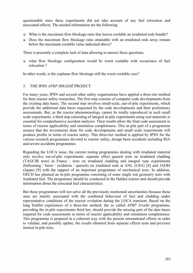
questionable since these experiments did not take account of any fuel relocation and associated effects. The needed information are the following.
What is the maximum flow blockage ratio that leaves coolable an irradiated rods bundle? Does the maximum flow blockage ratio attainable with an irradiated rods array remain below the maximum coolable value indicated above?
There is presently a complete lack of data allowing to answer these questions.
what flow blockage configuration would be worst coolable with occurrence of fuel relocation ?
In other words, is the coplanar flow blockage still the worst coolable case?
3. THE IPSN APRP IRRADIÉ PROJECT
For many years, IPSN and several other safety organisations have applied a three-tier method for their reactor safety researches. The first step consists of computer code developments from the existing data bases. The second step involves small-scale, out-of-pile experiments, which provide the additional data bases requested by the code developments and their preliminary assessments. But, as the reactor phenomenology cannot be totally reproduced in such small scale experiments, a third step consisting of integral in-pile experiments using real materials is essential for comprehensive accident analyses. Their results allow the final code assessment in terms of reactor applicability and simulation completeness. This in-pile part of a programme assures that the investments done for code developments and small scale experiments will produce profits in terms of reactor safety. This three-tier method is applied by IPSN for the various research programmes devoted to reactor safety, design basis accidents including RIA and severe accidents programmes.
Regarding the LOCA issue, the current testing programmes dealing with irradiated material only involve out-of-pile experiments: separate effect quench tests on irradiated cladding (TAGCIR tests) in France ; tests on irradiated cladding and integral type experiments (ballooning / burst / oxidation / quench) on irradiated rods at ANL (USA) [8] and JAERI (Japan) [9] with the support of an important programme of mechanical tests. In addition, OECD has planned an in-pile programme consisting of some single rod geometry tests with irradiated fuel. The programme should be conducted in the Halden reactor and should provide information about the relocated fuel characteristics.
But these programmes will not solve all the previously mentioned uncertainties because these ones are mainly associated with the combined behaviour of fuel and cladding under representative conditions of the reactor evolution during the LOCA transient. Based on the long fruitful experiences of a three-tier method, the so called APRP Irradié programme, providing the in-pile experiments third tier, should provide the missing part of the data bases required for code assessments in terms of reactor applicability and simulation completeness. This programme is prepared in a coherent way with the present international efforts in order to validate, and possibly update, the results obtained from separate effects tests and previous limited in-pile tests.
283

3.1. The Main Experimental Objectives
The main objectives of the in-pile experiments will be to investigate the behaviour of fuel and cladding with conditions representative of the reactor during LOCA sequences. The main factors that will be accounted for are:
the nature of fuel (UO2, MOX, Burn-up), the fuel-clad thermomechanical coupling (i.e. fuel relocation) thermal azimuthal gradients (main factor affecting cladding strain and blockage ratio) thermal-hydraulic aspects (i.e. quenching, coolability of blocked arrays)
3.2. Test Definition Rationale
The following analysis provides the rationale for the APRP-Irradié programme characteristics. It is shown that the conditions for having representative data for reactor applications are both in-pile tests and bundle geometry.
3.2.1. Needs for In-PileTests
The in-pile test need results from three reasons.
Neutron flux provides the unique way to produce the correct heat generation in the fuel fragments, corresponding to the residual power, whatever are the relocations induced by the ballooning and/or the burst of the rod. Both the exact amount of heat generation in the balloon and the heat exchanges with the rod channel depend on the characteristics of the relocated fuel fragments, their size, shapes, compaction ratio. This heat generation correctness is one of the main conditions for having realistic estimates of the relocation consequences in terms of equivalent clad reacted, peak clad temperature and hydrogen uptake inside the balloon. All these aspects impact the strength of the rod during the quenching phase and the residual ductility of the rod after the LOCA transient.
During the blowdown phase of the LOCA transient, there is much less heat generation in the fuel and the clad coolant heat transfer is drastically reduced. Therefore, the fuel stored energy is redistributed in the pellet and the cladding. Simultaneously, within a few seconds, this redistribution produces a decrease of the pellet center-line temperature from 1 500°C down to, say, 1 000°C and an increase of both the pellet rim and clad temperatures from 300°C up to 1 000°C. Due to these temperature transients, the central part of the pellet will experience a contraction while the rim and the clad will undergo an expansion. Fuel mechanical stresses and fragmentation could be induced by these adverse effects. It has to be kept in mind that during usual experiments, for which a blowdown phase is not reproduced, clad and fuel temperatures are simultaneously increased or decreased without producing any comparable thermomechanical transient. in-pile tests including a blowdown phase provide the way to get a definitive answer regarding the additional fuel fragmentation prior to the relocation and how much this refragmentation process affects the amount and the characteristics of the relocated fuel.
Finally, during reflooding and quench process studies, in-pile tests allow to maintain the heat generation in the fuel corresponding to the residual power. By this way, more representative conditions of the thermomechanical loads of the rods are provided. Without such a power
284

during the reflooding phase, steam production and cladding oxidation are reduced, the temperature transients experienced by the rods are less severe. Consequently, under estimates of core embrittling during reflooding could be obtained.
3.2.2. Needs for Bundle Geometry
In addition to the requirement associated to heat generation mentioned above, a bundle geometry is an second important condition to produce realistic data. Relocation being closely associated with the volume which is made free by the rod burst, it is clear that a correct amount of relocated fuel will be produced only if the sizes of the balloons are representative of the reactor conditions. Such balloon sizes can be obtained –as explained below- only with a bundle geometry. This is the reason why these tests are essential and complementary of single rod tests.
During the early stage of the LOCA transient the fuel rods experience the ballooning and burst processes. For such phenomena, a bundle geometry is a necessity to get a correct azimuthal temperature field around the fuel rods since this field is crucial to produce a realistic balloon size. An illustration of the impact of the azimuthal temperature field on the stain at burst is given by the results of single rod tests with heated or non shroud (see figure 4 below). An uniformly heated shroud reduces the azimuthal temperature variation around the rod. For such tests a higher rod deformation is obtained. Conversely, an unheated shroud tends to increase the azimuthal gradient and, therefore, leads to small rod deformation at strain
3
Fig. 4. Results of single rod tests.
285
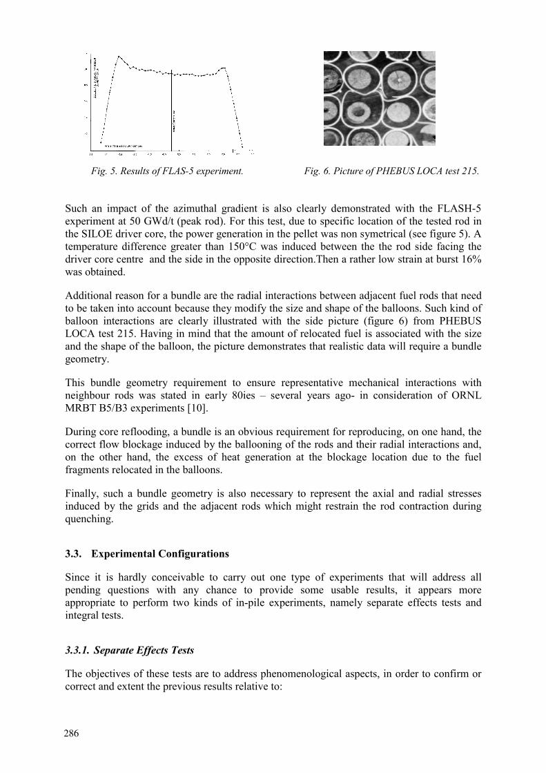
Fig. 5. Results of FLAS-5 experiment. Fig. 6. Picture of PHEBUS LOCA test 215.
Such an impact of the azimuthal gradient is also clearly demonstrated with the FLASH-5 experiment at 50 GWd/t (peak rod). For this test, due to specific location of the tested rod in the SILOE driver core, the power generation in the pellet was non symetrical (see figure 5). A temperature difference greater than 150°C was induced between the the rod side facing the driver core centre and the side in the opposite direction.Then a rather low strain at burst 16% was obtained.
Additional reason for a bundle are the radial interactions between adjacent fuel rods that need to be taken into account because they modify the size and shape of the balloons. Such kind of balloon interactions are clearly illustrated with the side picture (figure 6) from PHEBUS LOCA test 215. Having in mind that the amount of relocated fuel is associated with the size and the shape of the balloon, the picture demonstrates that realistic data will require a bundle geometry.
This bundle geometry requirement to ensure representative mechanical interactions with neighbour rods was stated in early 80ies – several years ago- in consideration of ORNL MRBT B5/B3 experiments [10].
During core reflooding, a bundle is an obvious requirement for reproducing, on one hand, the correct flow blockage induced by the ballooning of the rods and their radial interactions and, on the other hand, the excess of heat generation at the blockage location due to the fuel fragments relocated in the balloons.
Finally, such a bundle geometry is also necessary to represent the axial and radial stresses induced by the grids and the adjacent rods which might restrain the rod contraction during quenching.
3.3. Experimental Configurations
Since it is hardly conceivable to carry out one type of experiments that will address all pending questions with any chance to provide some usable results, it appears more appropriate to perform two kinds of in-pile experiments, namely separate effects tests and integral tests.
3.3.1. Separate Effects Tests
The objectives of these tests are to address phenomenological aspects, in order to confirm or correct and extent the previous results relative to:
286

rod deformation, fuel relocation, the resulting resistance to thermal shock loads, with or without effect of clad axial constraining.
These tests should be realised with one irradiated rod within a ring of 8 fresh fuel rods which will provide a representative thermal environment in order to ensure representative strains and subsequent phenomena. In addition, these in-pile separate effects tests should include a blowdown phase. As mentioned before, this phase will provide representative conditions for the temperature transient inside the fuel to study the consequences in terms of thermomechanical pre-fragmentation during blowdown.
3.3.2. Integral Tests
This kind of tests will address the aspects of :
impact of blowdown phase flow blockage quenching behaviour and coolability.
These tests should allow to check the absence of unexpected phenomena or unexpected coupling between foreseen processes, and finally provide data for the validation of reactor computational tools.
These tests should be realised with 9 high burn up rods with a ring of 12 or 16 fresh fuel rods which will provide a representative thermal environment in order to ensure representative strains and subsequent phenomena. A blowdown phase will be simulated depending on its importance as observed in the previous studies. Finally, additional axial stress during quenching due to rod blockage in the assembly should be simulated during these tests.
3.3.3. Experimental Facility
Such a programme is envisaged by the IPSN in the PHEBUS facility where some twenty LOCA tests were run between 76 and 83 [11,14], see figure 7. By this way IPSN would take advantage of the know-how accumulated when the previous LOCA programme with fresh fuel was run.
Fig. 7. Configuration of PHEBUS LOCA test.
287
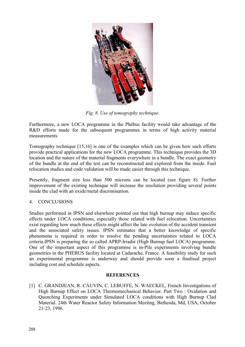
Fig. 8. Use of tomography technique.
Furthermore, a new LOCA programme in the Phébus facility would take advantage of the R&D efforts made for the subsequent programmes in terms of high activity material measurements
Tomography technique [15,16] is one of the examples which can be given how such efforts provide practical applications for the new LOCA programme. This technique provides the 3D location and the nature of the material fragments everywhere in a bundle. The exact geometry of the bundle at the end of the test can be reconstructed and explored from the inside. Fuel relocation studies and code validation will be made easier through this technique.
Presently, fragment size less than 500 microns can be located (see figure 8). Further improvement of the existing technique will increase the resolution providing several points inside the clad with an oxide/metal discrimination.
4. CONCLUSIONS
Studies performed in IPSN and elsewhere pointed out that high burnup may induce specific effects under LOCA conditions, especially those related with fuel relocation. Uncertainties exist regarding how much these effects might affect the late evolution of the accident transient and the associated safety issues. IPSN estimates that a better knowledge of specific phenomena is required in order to resolve the pending uncertainties related to LOCA criteria.IPSN is preparing the so called APRP-Irradié (High Burnup fuel LOCA) programme. One of the important aspect of this programme is in-Pile experiments involving bundle geometries in the PHEBUS facility located at Cadarache, France. A feasibility study for such an experimental programme is underway and should provide soon a finalised project including cost and schedule aspects.
REFERENCES
[1] C. GRANDJEAN, R. CAUVIN, C. LEBUFFE, N. WAECKEL, French Investigations of High Burnup Effect on LOCA Thermomechanical Behavior. Part Two : Oxidation and Quenching Experiments under Simulated LOCA conditions with High Burnup Clad Material. 24th Water Reactor Safety Information Meeting, Bethesda, Md, USA, October 21-23, 1996.
288
[2] C. GRANDJEAN, R. CAUVIN, P. JACQUES, Oxidation and Quenching Experiments with High Burnup Cladding under LOCA conditions. Revision of previous data and main trends of recent tests. 26th Water Reactor Safety Information Meeting, Bethesda, Md, USA, October 26-28, 1998
[3] H. UETSUKA, T. FURUTA, S. KAWASAKI, Failure-Bearing Capability of Oxidized Zircaloy-4 Cladding under Simulated Loss-of-Coolant Condition. J. Nucl. Sc. and Tech., 20 (11), pp 941-950, Nov. 1983.
[4] J.M. BROUGHTON et al., PBF LOCA Tests Series. Tests LOC3 and LOC5 Fuel Behavior Report. NUREG/CR 2073, June 1981.
[5] J.M. BROUGHTON et al., PBF LOCA Test LOC6 Fuel Behavior Report. NUREG/CR 3184, April 1983.
[6] E.H. KARB et al., LWR Fuel Rod Behavior in the FR2 in-pile Tests Simulating the Heat-up Phase of a LOCA. KFK 3346, March 1983
[7] M. BRUET et al., High Burnup Fuel Behavior during a LOCA Type Accident : The FLASH5 Experiment. IAEA Technical Committee Meeting Behavior of Core Material and F.P. Release in Accident Conditions in LWRs, Cadarache, France, March 16-20,1992.
[8] M.C. BILLONE et al., Test Plan for the Investigation of High Burnup LWR Cladding under LOCA and other Transient Conditions. IPS-263-Rev. 2, ANL Program Review Meeting, Bethesda, Md, October 29, 1998.
[9] H. UETSUKA, Experimental Program on High Burnup Fuel Cladding Behavior under LOCA and other Transient Conditions at JAERI. 22nd NSRR Technical Review Meeting, Tokyo, November 9-10,1998.
[10] R. H. CHAPMAN et al. Effect of Bundle Size on Cladding Deformation in Loca Simulation Tests. 6th Int. Symp. Zirc. In the Nucl. Ind. ASM STP824, 1984, pp693-708.
[11] J. DUCO, M. RÉOCREUX, A. TATTEGRAIN, PH. BERNA, B. LEGRAND, M. TROTABAS, In-pile investigations at the Phebus facility of the behavior of PWR-type fuel bundles in typical L.B. LOCA transients extended to and beyond the limits of ECCS criteria, 5th International meeting on Thermal Reactor Safety, KarIsruhe, Sept. 10-13, 1984.
[12] E.F. SCOTT de MARTINVILLE, M.R. PIGNARD, International Standard Problem No. 19: Behaviour of a fuel rod bundle during a large break LOCA transient with a two peak temperature history, CSNI Report No. 133, (1987).
[13] E.F. SCOTT de MARTINVILLE, C.R. GONNIER, Thermomechanics of a nuclear fuel bundle submitted to an L.B. LOCA evaluation transient: lessons drawn from the Phebus LOCA program, 9th SMIRT Conference, Lausanne, August 1987.
[14] C. GONNIER, S. FABRÉGA, E. SCOTT, G. GEOFFROY "In pile investigations at the Phebus facility on the behaviour of PWR-type fuel bundles in severe accident conditions beyond the design criteria" SFEN - NUCSAFE 88 Avignon 2, 7 October 1988.
[15] Von der HARDT, P., JONES, A.V., LECOMTE, C., TATTEGRAIN, A., “Nuclear Safety Research. The Phebus FP Severe Accident Experimental Programme”, Nuclear Safety, Vol. 35(2), July-December; 1994, pp. 187-205
[16] M. SCHWARZ, B. CLÉMENT, A.V. JONES “Applicability of Phebus_FP Results to Severe Accident Safety Evaluations and Management Measures”, FISA-99, EC-Luxembourg, 29Nov-1Dec 1999
289

LIST OF PARTICIPANTS
BELGIUM
J. Zhang Tractebel Energy Engineering, Nuclear Engineering Department, Avenue Ariane 7, B-1200 Brussels
CANADA
J.C. Luxat Ontario Power Generation, 700 University Avenue, Toronto, ON, M5G 1X6
EGYPT
M.K. Shaat Nuclear Research Centre, Atomic Energy Authority Cairo, 3 Ahmed El-Zomor St. Nacr City, El-Sohvor DTST, Cairo 11787
FINLAND
K. Ranta-Puska VTT Energy, Tekniikantie 4, P.O. Box 1604, FIN-02044 VTT
M. Henrikki Pihlatie Fortum Nuclear Services Oy, PL 10, 00048 Fortum
FRANCE
P. Yvon CEA-Saclay, DMN/SEMI, F-91191 Gif-Sur-Yvette
G. Hache Institut de Protection et de Sûreté Nucléaire, Département de Recherches en Sécurité, BATIMENT 250, Cadarache, F-13108 Saint-Paul-lez-Durance Cedex
J.C. Brachet CEA-Sacleay, DMS/SRMA, F-91191 Gif-Sur-Yvette
F. Touboul CEA Saclay, DEN/DSNI/SURELE, Batriment 121, F-91191 Gif-Sur-Yvette
D.P. Parrat DEC/S3C/LTC, CEA Cadarache, BP1, F-13108 Saint-Paul-Lez-Durance
E. Federici DRS/SEMAR, CE-CADARACHE, F-13108 Saint-Paul-Lez-Durance
A. Maillat CE, CADARACHE, IPSN/DRS Bât. 245, F-13108 Saint-Paul-lez-Durance
291
C. Grandjean IPSN/DRS/SEMAR Bât. 700, F-13108 Saint-Paul-lez-Durance
A. Le Bourhis FRAMATOME ANP (Nuclear Fuel), 10 Rue J. Recamier, F-69456 Lyon Cedex 06
GERMANY
E. Mrosk TÜV Nord e.v., Grosse Bahnstrasse 31, D-22525 Hamburg
HUNGARY
J. Zsoldos Hungarian Atomic Energy Authority, Nuclear Safety Directorate, 11. Margit Krt. 85, P.O.Box 676, H-1539 Budapest 114
Z. Hozer KFKI Atomic Energy Research Institute, H-1121 Budapest, Konkoly Thege u. 29-33
INDIA
H.G. Lele Bhabha Atomic Research Centre, Reactor Safety Division, Engs Hall 7, BARC, Trombay, Mumbai 400094
JAPAN
T. Nakano Research & Development Department, Nuclear Development Corporation, 622-12 Funaishikawa, Tokai-mura, Ibaraki 319-1111
T. Sugiyama Department of Reactor Safety Research, Japan Atomic Energy Research Institute, Tokai-mura, Naka-gun, Ibaraki 319-1195,
Present mailing address: IFE, OECD Halden Reactor Project, P.O. Box 173, N-1751 Halden, Norway
M. Tanimoto Department of Reactor Safety Research, Japan Atomic Energy Research Institute (JAERI), Tokai-mura, Naka-gun, Ibaraki, 319-1195
H. Hayashi NUPEC, 3-17-1 Toranomon, Minato-ku, Tokyo
292
REPUBLIC OF KOREA
B.-Ho Lee Korea Atomic Energy Research Institute, P.O. Box 105 Yuseong, Daejeon, 305-600
Present mailing address: Institute for Energiteknikk, OECD Halden Research Project, P.O. Box 173, N-1751, Norway
J.G. Bang Korea Atomic Energy Research Institute, Yusung P.O.Box 105, Taejon
NORWAY
E. Kolstad Institutt for Energiteknikk, OECD Halden Reactor Project, Postboks 173, N-1751 Halden
K. Lunde Institute for Energiteknikk, Postboks 40, N-2027 Kjeller
W. Wiesenack Institutt for Energiteknikk, OECD Halden Reactor Project, Postboks 173, N-1751 Halden
RUSSIAN FEDERATION
A. Viktorovich Salatov Botchvar Institute of Inorganic Materials, Moscow VNINM, P.O.Box 369, 123060 Moscow
L.N. Andreeva-Andrievskaya Botchvar Institute of Inorganic Materials, Moscow, VNINM, P.O.Box 369, 123060 Moscow
O. Artiemovna Nachaeva Botchvar Institute of Inorganic Materials, Moscow, VNINM, P.O. Box 369, 123060 Moscow
I.V. Pimenov JSC <<TVEL>>, 24/26 B. Odynka St., Moscow 101000
SPAIN
F.J. Barrio Departamento de Fision Nuclear del CIEMAT, Avda. Complutense. 22, 28040 Madrid
J.M. Rey Consejo de Seguridad Nuclear (CSN), C/Justo Dorado 11, 28040 Madrid
SWEDEN
B. Andersson Forsmarks Kraftgrupp AB, S-74203 Östhammar
293

S.Gunnar Ronnberg OKG, S-57283 Oskarshamn
T.B. Andersson RINGHALS AB, SE-430 22 VÄRÖBACKA
J. In De Betou Swedish Nuclear Power Inspectorate, S-106 58 Stockholm
P. Lansaker Forsmarks Kraftgrupp AB, S-74203 Östhammar
SWITZERLAND
D.G. Loy Haupabteilung für die Sicherheit der Kernanlagen (HSK), CH-5232 Villigen-HSK
L.A. Nordstrom Paul Scherrer Institut, CH-5232 Villigen-PSI
F. Holzgrewe BKW-FMB Energie AG, KKM-Mühleberg, CH-3203 Mühleberg
OECD/NEA
M. Hrehor Nuclear Safety Division, OECD Nuclear Energy Agency, Le Seine St-Germain; 12, Boulevard deslles, F-92130 Issy-les-Moulineaux
C. Vitanza Nuclear Safety Division, OECD Nuclear Energy Agency, Le Seine St-Germain; 12, Boulevard deslles, F-92130 Issy-les-Moulineaux
OECD Halden Reactor Project
H. Thoresen M. Nishi K. Eriksen A. Valseth Y. Minagawa M. Mcgrath T. Tverberg G. Rossiter P. Tolonen B. Volkov H. Ruhmann
294


![Quique Hache Detective[1]](https://img.pdfslide.us/doc/110x75/5571ffa349795991699dbcb7/quique-hache-detective1.jpg)