Embed Size (px)
Citation preview
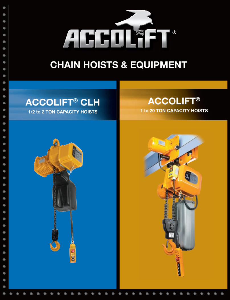
CHAIN HOISTS & EQUIPMENT
®®
ACCOLIFT® CLH1/2 to 2 TON CAPACITY HOISTS
ACCOLIFT®
1 to 20 TON CAPACITY HOISTS
36518_Combo Cat_.qxp_Layout 1 6/21/17 7:43 AM Page 2
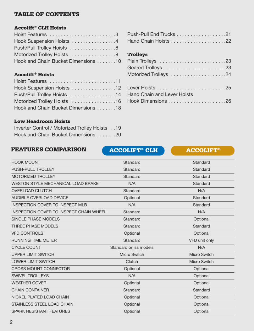
FEATURES COMPARISON
HOOK MOUNT Standard Standard
PUSH-PULL TROLLEY Standard Standard
MOTORIZED TROLLEY Standard Standard
WESTON STYLE MECHANICAL LOAD BRAKE N/A Standard
OVERLOAD CLUTCH Standard N/A
AUDIBLE OVERLOAD DEVICE Optional Standard
INSPECTION COVER TO INSPECT MLB N/A Standard
INSPECTION COVER TO INSPECT CHAIN WHEEL Standard N/A
SINGLE PHASE MODELS Standard Optional
THREE PHASE MODELS Standard Standard
VFD CONTROLS Optional Optional
RUNNING TIME METER Standard VFD unit only
CYCLE COUNT Standard on ss models N/A
UPPER LIMIT SWITCH Micro Switch Micro Switch
LOWER LIMIT SWITCH Clutch Micro Switch
CROSS MOUNT CONNECTOR Optional Optional
SWIVEL TROLLEYS N/A Optional
WEATHER COVER Optional Optional
CHAIN CONTAINER Standard Standard
NICKEL PLATED LOAD CHAIN Optional Optional
STAINLESS STEEL LOAD CHAIN Optional Optional
SPARK RESISTANT FEATURES Optional Optional
ACCOLIFT®ACCOLIFT® CLH
2
TABLE OF CONTENTS
Accolift® CLH HoistsHoist Features . . . . . . . . . . . . . . . . . . . . . . . .3Hook Suspension Hoists . . . . . . . . . . . . . . . .4Push/Pull Trolley Hoists . . . . . . . . . . . . . . . . .6Motorized Trolley Hoists . . . . . . . . . . . . . . . .8Hook and Chain Bucket Dimensions . . . . . . .10
Accolift® HoistsHoist Features . . . . . . . . . . . . . . . . . . . . . . . .11Hook Suspension Hoists . . . . . . . . . . . . . . . .12Push/Pull Trolley Hoists . . . . . . . . . . . . . . . . .14Motorized Trolley Hoists . . . . . . . . . . . . . . . .16Hook and Chain Bucket Dimensions . . . . . . .18
Low Headroom HoistsInverter Control / Motorized Trolley Hoists . .19Hook and Chain Bucket Dimensions . . . . . . .20
Push-Pull End Trucks . . . . . . . . . . . . . . . . . .21Hand Chain Hoists . . . . . . . . . . . . . . . . . . . .22
TrolleysPlain Trolleys . . . . . . . . . . . . . . . . . . . . . . . .23Geared Trolleys . . . . . . . . . . . . . . . . . . . . . .23Motorized Trolleys . . . . . . . . . . . . . . . . . . . .24
Lever Hoists . . . . . . . . . . . . . . . . . . . . . . . . .25Hand Chain and Lever Hoists Hook Dimensions . . . . . . . . . . . . . . . . . . . . .26
36518_Combo Cat_.qxp_Layout 1 6/21/17 7:43 AM Page 3
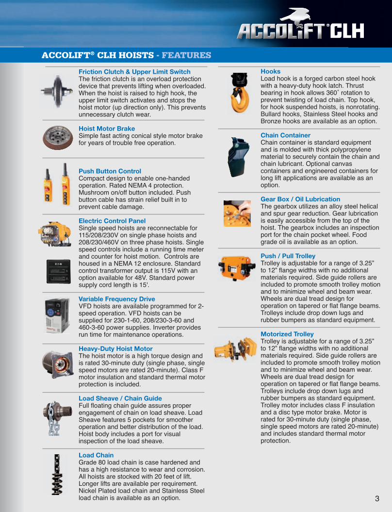
Friction Clutch & Upper Limit SwitchThe friction clutch is an overload protectiondevice that prevents lifting when overloaded.When the hoist is raised to high hook, theupper limit switch activates and stops thehoist motor (up direction only). This preventsunnecessary clutch wear.
Hoist Motor BrakeSimple fast acting conical style motor brakefor years of trouble free operation.
Push Button ControlCompact design to enable one-handedoperation. Rated NEMA 4 protection.Mushroom on/off button included. Pushbutton cable has strain relief built in toprevent cable damage.
Electric Control PanelSingle speed hoists are reconnectable for115/208/230V on single phase hoists and208/230/460V on three phase hoists. Singlespeed controls include a running time meterand counter for hoist motion. Controls arehoused in a NEMA 12 enclosure. Standardcontrol transformer output is 115V with anoption available for 48V. Standard powersupply cord length is 15'.
Variable Frequency DriveVFD hoists are available programmed for 2-speed operation. VFD hoists can besupplied for 230-1-60, 208/230-3-60 and460-3-60 power supplies. Inverter providesrun time for maintenance operations.
Heavy-Duty Hoist MotorThe hoist motor is a high torque design andis rated 30-minute duty (single phase, singlespeed motors are rated 20-minute). Class Fmotor insulation and standard thermal motorprotection is included.
Load Sheave / Chain GuideFull floating chain guide assures properengagement of chain on load sheave. LoadSheave features 5 pockets for smootheroperation and better distribution of the load.Hoist body includes a port for visualinspection of the load sheave.
Load ChainGrade 80 load chain is case hardened andhas a high resistance to wear and corrosion.All hoists are stocked with 20 feet of lift.Longer lifts are available per requirement.Nickel Plated load chain and Stainless Steelload chain is available as an option. 3
ACCOLIFT® CLH HOISTS - FEATURES
®®
HooksLoad hook is a forged carbon steel hookwith a heavy-duty hook latch. Thrustbearing in hook allows 360˚ rotation toprevent twisting of load chain. Top hook,for hook suspended hoists, is nonrotating.Bullard hooks, Stainless Steel hooks andBronze hooks are available as an option.
Chain ContainerChain container is standard equipmentand is molded with thick polypropylenematerial to securely contain the chain andchain lubricant. Optional canvascontainers and engineered containers forlong lift applications are available as anoption.
Gear Box / Oil LubricationThe gearbox utilizes an alloy steel helicaland spur gear reduction. Gear lubricationis easily accessible from the top of thehoist. The gearbox includes an inspectionport for the chain pocket wheel. Foodgrade oil is available as an option.
Push / Pull TrolleyTrolley is adjustable for a range of 3.25”to 12” flange widths with no additionalmaterials required. Side guide rollers areincluded to promote smooth trolley motionand to minimize wheel and beam wear.Wheels are dual tread design foroperation on tapered or flat flange beams.Trolleys include drop down lugs andrubber bumpers as standard equipment.
Motorized Trolley Trolley is adjustable for a range of 3.25”to 12” flange widths with no additionalmaterials required. Side guide rollers areincluded to promote smooth trolley motionand to minimize wheel and beam wear.Wheels are dual tread design foroperation on tapered or flat flange beams.Trolleys include drop down lugs andrubber bumpers as standard equipment.Trolley motor includes class F insulationand a disc type motor brake. Motor israted for 30-minute duty (single phase,single speed motors are rated 20-minute)and includes standard thermal motorprotection.
36518_Combo Cat_.qxp_Layout 1 6/21/17 7:43 AM Page 4
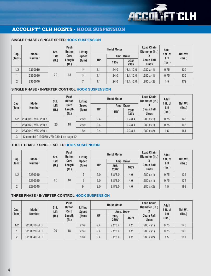
SINGLE PHASE / INVERTER CONTROL HOOK SUSPENSION
1/2 2330010-VFD-230-1 20 18 27/9 2.4 - 9.2/8.4 .280 x (1) 0.75 148
1 2330020-VFD-230-1 20 18 27/9 2.4 - 9.2/8.4 .280 x (1) 0.75 148
2 2330040-VFD-230-1 20 18 13/4 2.4 - 9.2/8.4 .280 x (2) 1.5 181
3 See model 2130060-VFD-230-1 on page 12.
ACCOLIFT® CLH HOISTS - HOOK SUSPENSION
SINGLE PHASE / SINGLE SPEED HOOK SUSPENSION
1/2 2330010 20 18 14 1.1 24.0 13.1/12.0 .280 x (1) 0.75 139
1 2330020 20 18 14 1.1 24.0 13.1/12.0 .280 x (1) 0.75 139
2 2330040 20 18 7 1.1 24.0 13.1/12.0 .280 x (2) 1.5 172
Add’l1 ft. of
Lift(lbs.)
Net Wt.(lbs.)
Load ChainDiameter (in.)
XChain Fall
Lines
Amp. Draw
Hoist Motor
208/230V
208/230V
115VHP
LiftingSpeed(fpm)
PushButtonCord
Length(ft.)
Std.Lift (ft.)
Model Number
Cap.(Tons)
THREE PHASE / SINGLE SPEED HOOK SUSPENSION
1/2 2230010 20 18 17 2.0 8.8/8.0 4.0 .280 x (1) 0.75 134
1 2230020 20 18 17 2.0 8.8/8.0 4.0 .280 x (1) 0.75 134
2 2230040 20 18 9 2.0 8.8/8.0 4.0 .280 x (2) 1.5 168
Add’l1 ft. of
Lift(lbs.)
Net Wt.(lbs.)
Load ChainDiameter (in.)
XChain Fall
Lines
Amp. Draw
Hoist Motor
460V208/230V
HP
LiftingSpeed(fpm)
PushButtonCord
Length(ft.)
Std.Lift (ft.)
Model Number
Cap.(Tons)
Add’l1 ft. of
Lift(lbs.)
Net Wt.(lbs.)
Load ChainDiameter (in.)
XChain Fall
Lines
Amp. Draw
Hoist Motor
115VHP
LiftingSpeed(fpm)
PushButtonCord
Length(ft.)
Std.Lift (ft.)
Model Number
Cap.(Tons)
THREE PHASE / INVERTER CONTROL HOOK SUSPENSION
1/2 2230010-VFD 20 18 27/9 2.4 9.2/8.4 4.2 .280 x (1) 0.75 146
1 2230020-VFD 20 18 27/9 2.4 9.2/8.4 4.2 .280 x (1) 0.75 146
2 2230040-VFD 20 18 13/4 2.4 9.2/8.4 4.2 .280 x (2) 1.5 181
Add’l1 ft. of
Lift(lbs.)
Net Wt.(lbs.)
Load ChainDiameter (in.)
XChain Fall
Lines
Amp. Draw
Hoist Motor
460V208/230V
HP
LiftingSpeed(fpm)
PushButtonCord
Length(ft.)
Std.Lift (ft.)
Model Number
Cap.(Tons)
®®®
4
20 18
20 18
20 18
20 18
36518_Combo Cat_.qxp_Layout 1 6/21/17 7:43 AM Page 5
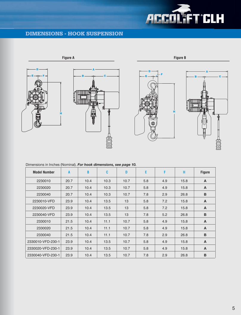
DIMENSIONS - HOOK SUSPENSION
®®®
Dimensions in Inches (Nominal). For hook dimensions, see page 10.
Model Number A B C D E F H Figure
2230010 20.7 10.4 10.3 10.7 5.8 4.9 15.8 A
2230020 20.7 10.4 10.3 10.7 5.8 4.9 15.8 A
2230040 20.7 10.4 10.3 10.7 7.8 2.9 26.8 B
2230010-VFD 23.9 10.4 13.5 13 5.8 7.2 15.8 A
2230020-VFD 23.9 10.4 13.5 13 5.8 7.2 15.8 A
2230040-VFD 23.9 10.4 13.5 13 7.8 5.2 26.8 B
2330010 21.5 10.4 11.1 10.7 5.8 4.9 15.8 A
2330020 21.5 10.4 11.1 10.7 5.8 4.9 15.8 A
2330040 21.5 10.4 11.1 10.7 7.8 2.9 26.8 B
2330010-VFD-230-1 23.9 10.4 13.5 10.7 5.8 4.9 15.8 A
2330020-VFD-230-1 23.9 10.4 13.5 10.7 5.8 4.9 15.8 A
2330040-VFD-230-1 23.9 10.4 13.5 10.7 7.8 2.9 26.8 B
Figure BFigure A
E F
D
H
A
B C
H
E
DF
A
B C
5
36518_Combo Cat_.qxp_Layout 1 6/21/17 7:43 AM Page 6
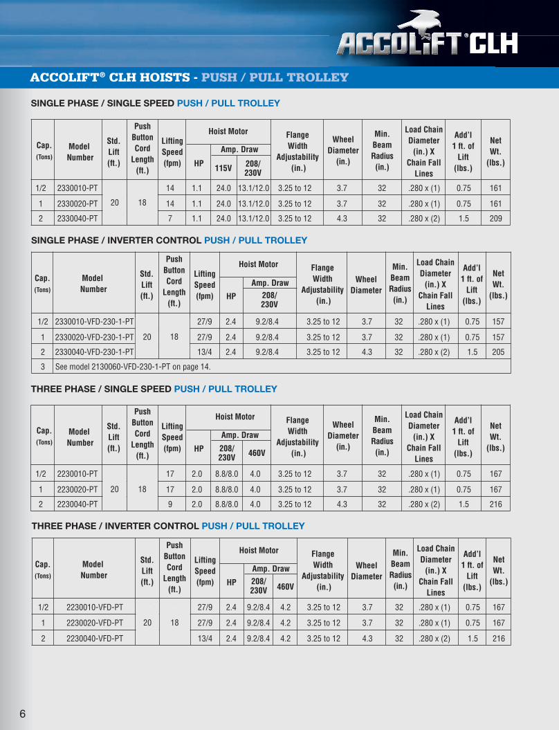
SINGLE PHASE / INVERTER CONTROL PUSH / PULL TROLLEY
1/2 2330010-VFD-230-1-PT 20 18 27/9 2.4 9.2/8.4 3.25 to 12 3.7 32 .280 x (1) 0.75 157
1 2330020-VFD-230-1-PT 20 18 27/9 2.4 9.2/8.4 3.25 to 12 3.7 32 .280 x (1) 0.75 157
2 2330040-VFD-230-1-PT 20 18 13/4 2.4 9.2/8.4 3.25 to 12 4.3 32 .280 x (2) 1.5 205
3 See model 2130060-VFD-230-1-PT on page 14.
THREE PHASE / SINGLE SPEED PUSH / PULL TROLLEY
1/2 2230010-PT 20 18 17 2.0 8.8/8.0 4.0 3.25 to 12 3.7 32 .280 x (1) 0.75 167
1 2230020-PT 20 18 17 2.0 8.8/8.0 4.0 3.25 to 12 3.7 32 .280 x (1) 0.75 167
2 2230040-PT 20 18 9 2.0 8.8/8.0 4.0 3.25 to 12 4.3 32 .280 x (2) 1.5 216
SINGLE PHASE / SINGLE SPEED PUSH / PULL TROLLEY
1/2 2330010-PT 20 18 14 1.1 24.0 13.1/12.0 3.25 to 12 3.7 32 .280 x (1) 0.75 161
1 2330020-PT 20 18 14 1.1 24.0 13.1/12.0 3.25 to 12 3.7 32 .280 x (1) 0.75 161
2 2330040-PT 20 18 7 1.1 24.0 13.1/12.0 3.25 to 12 4.3 32 .280 x (2) 1.5 209
ACCOLIFT® CLH HOISTS - PUSH / PULL TROLLEY
6
Cap.(Tons)
Std.Lift(ft.)
PushButtonCord
Length(ft.)
LiftingSpeed(fpm) HP 115V
208/230V
208/230V
Flange Width
Adjustability(in.)
Min.BeamRadius(in.)
WheelDiameter
(in.)
Load ChainDiameter
(in.) XChain Fall
Lines
NetWt.
(lbs.)
Add’l1 ft. of
Lift(lbs.)
ModelNumber
Hoist Motor
Amp. Draw
Cap.(Tons)
Std.Lift(ft.)
PushButtonCord
Length(ft.)
LiftingSpeed(fpm) HP 208/
230V 460V
Flange Width
Adjustability(in.)
Min.BeamRadius(in.)
WheelDiameter
(in.)
Load ChainDiameter
(in.) XChain Fall
Lines
NetWt.
(lbs.)
Add’l1 ft. of
Lift(lbs.)
ModelNumber
Hoist Motor
Amp. Draw
Cap.(Tons)
Std.Lift(ft.)
PushButtonCord
Length(ft.)
LiftingSpeed(fpm) HP
Flange Width
Adjustability(in.)
Min.BeamRadius(in.)
Load ChainDiameter
(in.) XChain Fall
Lines
NetWt.
(lbs.)
Add’l1 ft. of
Lift(lbs.)
ModelNumber
Hoist Motor
Amp. Draw WheelDiameter
THREE PHASE / INVERTER CONTROL PUSH / PULL TROLLEY
1/2 2230010-VFD-PT 20 18 27/9 2.4 9.2/8.4 4.2 3.25 to 12 3.7 32 .280 x (1) 0.75 167
1 2230020-VFD-PT 20 18 27/9 2.4 9.2/8.4 4.2 3.25 to 12 3.7 32 .280 x (1) 0.75 167
2 2230040-VFD-PT 20 18 13/4 2.4 9.2/8.4 4.2 3.25 to 12 4.3 32 .280 x (2) 1.5 216
Cap.(Tons)
Std.Lift(ft.)
PushButtonCord
Length(ft.)
LiftingSpeed(fpm) HP 208/
230V 460V
Flange Width
Adjustability(in.)
Min.BeamRadius(in.)
Load ChainDiameter
(in.) XChain Fall
Lines
NetWt.
(lbs.)
Add’l1 ft. of
Lift(lbs.)
ModelNumber
Hoist Motor
Amp. Draw WheelDiameter
®®®
20 18
20 18
20 18
20 18
36518_Combo Cat_.qxp_Layout 1 6/21/17 7:43 AM Page 7

DIMENSIONS - PUSH / PULL TROLLEY
7
®
Dimensions in Inches (Nominal). For hook dimensions, see page 10.
Model Number A B C D E F H I J K WB Figure
2230010-PT 17 1.8 15.2-W 5.8 4.9 16 17.5 10.4 10.3 5.2 4.4 A
2230020-PT 17 1.8 15.2-W 5.8 4.9 16 17.5 10.4 10.3 5.2 4.4 A
2230040-PT 17.5 1.8 15.7-W 7.8 2.9 16.7 26 10.4 10.3 5.2 4.9 B
2230010-VFD-PT 17 1.8 15.2-W 5.8 7.1 16 17.5 10.4 13.5 5.2 4.4 A
2230020-VFD-PT 17 1.8 15.2-W 5.8 7.1 16 17.5 10.4 13.5 5.2 4.4 A
2230040-VFD-PT 17.5 1.8 15.7-W 7.8 5.1 16.7 26 10.4 13.5 5.2 4.9 B
2330010-PT 17 1.8 15.2-W 5.8 4.9 16 17.5 10.4 11.1 5.2 4.4 A
2330020-PT 17 1.8 15.2-W 5.8 4.9 16 17.5 10.4 11.1 5.2 4.4 A
2330040-PT 17.5 1.8 15.7-W 7.8 2.9 16.7 26 10.4 11.1 5.2 4.9 B
2330010-VFD-1-PT 17 1.8 15.2-W 5.8 4.9 16 17.5 10.4 13.5 5.2 4.4 A
2330020-VFD-1-PT 17 1.8 15.2-W 5.8 4.9 16 17.5 10.4 13.5 5.2 4.4 A
2330040-VFD-1-PT 17.5 1.8 15.7-W 7.8 2.9 16.7 26 10.4 13.5 5.2 4.9 B
W = Beam width
Figure BFigure A
C WA
F
WBWB
H
C
A F
B
H
K
JI
W
B
ED
K
I JD
E
36518_Combo Cat_.qxp_Layout 1 6/21/17 7:43 AM Page 8

ACCOLIFT® CLH HOISTS - MOTORIZED TROLLEY
8
®®®
SINGLE PHASE / SINGLE SPEED MOTORIZED TROLLEY
1/2 2330110 20 18 14 36 1.1 24.0 13.1/12.0 0.27 7.8 4.3/3.9 3.25 to 12 3.7 32 .280 x (1) 0.75 225
1 2330120 20 18 14 36 1.1 24.0 13.1/12.0 0.27 7.8 4.3/3.9 3.25 to 12 3.7 32 .280 x (1) 0.75 225
2 2330140 20 18 7 36 1.1 24.0 13.1/12.0 0.27 7.8 4.3/3.9 3.25 to 12 4.3 32 .280 x (2) 1.5 273
Cap.
(Tons)
Std.Lift(ft.)
PushButtonCord
Length(ft.)
LiftingSpeed(fpm)
TrolleySpeed(fpm) HP 115V HP208/
230V 115V208/230V Standard
Min.BeamRadius(in.)
Load ChainDiameter
(in.) XChain Fall
Lines
NetWt.
(lbs.)
Add’l1 ft. of
Lift(lbs.)
ModelNumber
Hoist Motor Trolley Motor
Amp. Draw Amp. Draw
Flange WidthAdjustability
(in.)WheelDia.
SINGLE PHASE / INVERTER CONTROL MOTORIZED TROLLEY
1/2 2330110-VFD-230-1 20 18 27/9 75/25 2.4 - 9.2/8.4 0.54 - 3.3/3.0 3.25 to 12 3.7 32 .280 x (1) 0.75 227
1 2330120-VFD-230-1 20 18 27/9 75/25 2.4 - 9.2/8.4 0.54 - 3.3/3.0 3.25 to 12 3.7 32 .280 x (1) 0.75 227
2 2330140-VFD-230-1 20 18 13/4 75/25 2.4 - 9.2/8.4 0.54 - 3.3/3.0 3.25 to 12 4.3 32 .280 x (2) 1.5 280
3 See model 2130160-VFD-230-1 on page 16.
Cap.
(Tons)
Std.Lift(ft.)
PushButtonCord
Length(ft.)
LiftingSpeed(fpm)
TrolleySpeed(fpm) HP 115V HP208/
230V 115V208/230V Standard
Min.BeamRadius(in.)
Load ChainDiameter
(in.) XChain Fall
Lines
NetWt.
(lbs.)
Add’l1 ft. of
Lift(lbs.)
ModelNumber
Hoist Motor Trolley Motor
Amp. Draw Amp. Draw
Flange WidthAdjustability
(in.)WheelDia.
THREE PHASE / SINGLE SPEED MOTORIZED TROLLEY
1/2 2230110 20 18 17 36 2.0 8.8/8.0 4.0 0.54 3.3/3.0 1.5 3.25 to 12 3.7 32 .280 x (1) 0.75 221
1 2230120 20 18 17 36 2.0 8.8/8.0 4.0 0.54 3.3/3.0 1.5 3.25 to 12 3.7 32 .280 x (1) 0.75 221
2 2230140 20 18 9 36 2.0 8.8/8.0 4.0 0.54 3.3/3.0 1.5 3.25 to 12 4.3 32 .280 x (2) 1.5 269
Cap.
(Tons)
Std.Lift(ft.)
PushButtonCord
Length(ft.)
LiftingSpeed(fpm)
TrolleySpeed(fpm) HP 460V HP208/
230V 460V208/230V Standard
Min.BeamRadius(in.)
Load ChainDiameter
(in.) XChain Fall
Lines
NetWt.
(lbs.)
Add’l1 ft. of
Lift(lbs.)
ModelNumber
Hoist Motor Trolley Motor
Amp. Draw Amp. Draw
Flange WidthAdjustability
(in.)WheelDia.
THREE PHASE / INVERTER CONTROL MOTORIZED TROLLEY
1/2 2230110-VFD 20 18 27/9 75/25 2.4 9.2/8.4 4.2 0.54 3.3/3.0 1.5 3.25 to 12 3.7 32 .280 x (1) 0.75 231
1 2230120-VFD 20 18 27/9 75/25 2.4 9.2/8.4 4.2 0.54 3.3/3.0 1.5 3.25 to 12 3.7 32 .280 x (1) 0.75 231
2 2230140-VFD 20 18 13/4 75/25 2.4 9.2/8.4 4.2 0.54 3.3/3.0 1.5 3.25 to 12 4.3 32 .280 x (2) 1.5 280
Cap.
(Tons)
Std.Lift(ft.)
PushButtonCord
Length(ft.)
LiftingSpeed(fpm)
TrolleySpeed(fpm) HP 460V HP208/
230V 460V208/230V Standard
Min.BeamRadius(in.)
Load ChainDiameter
(in.) XChain Fall
Lines
NetWt.
(lbs.)
Add’l1 ft. of
Lift(lbs.)
ModelNumber
Hoist Motor Trolley Motor
Amp. Draw Amp. Draw
Flange WidthAdjustability
(in.)WheelDia.
20 18
20 18
20 18
20 18
36518_Combo Cat_.qxp_Layout 1 6/21/17 7:43 AM Page 9
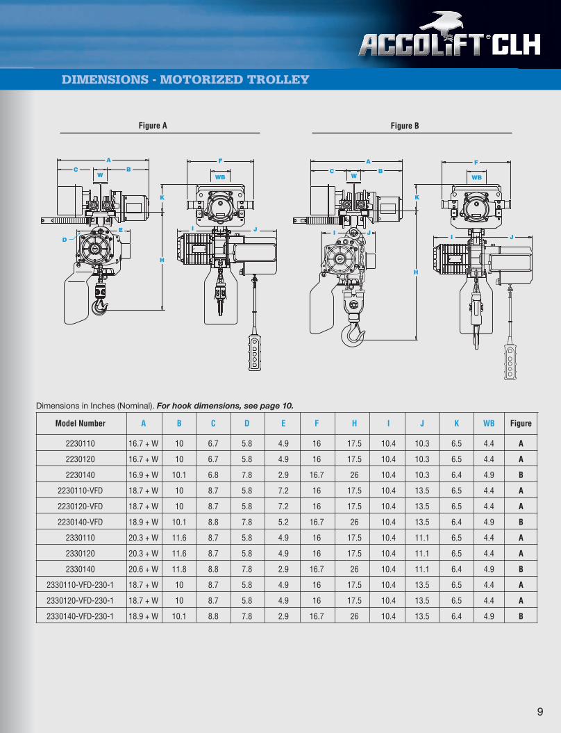
Dimensions in Inches (Nominal). For hook dimensions, see page 10.
Model Number A B C D E F H I J K WB Figure
2230110 16.7 + W 10 6.7 5.8 4.9 16 17.5 10.4 10.3 6.5 4.4 A
2230120 16.7 + W 10 6.7 5.8 4.9 16 17.5 10.4 10.3 6.5 4.4 A
2230140 16.9 + W 10.1 6.8 7.8 2.9 16.7 26 10.4 10.3 6.4 4.9 B
2230110-VFD 18.7 + W 10 8.7 5.8 7.2 16 17.5 10.4 13.5 6.5 4.4 A
2230120-VFD 18.7 + W 10 8.7 5.8 7.2 16 17.5 10.4 13.5 6.5 4.4 A
2230140-VFD 18.9 + W 10.1 8.8 7.8 5.2 16.7 26 10.4 13.5 6.4 4.9 B
2330110 20.3 + W 11.6 8.7 5.8 4.9 16 17.5 10.4 11.1 6.5 4.4 A
2330120 20.3 + W 11.6 8.7 5.8 4.9 16 17.5 10.4 11.1 6.5 4.4 A
2330140 20.6 + W 11.8 8.8 7.8 2.9 16.7 26 10.4 11.1 6.4 4.9 B
2330110-VFD-230-1 18.7 + W 10 8.7 5.8 4.9 16 17.5 10.4 13.5 6.5 4.4 A
2330120-VFD-230-1 18.7 + W 10 8.7 5.8 4.9 16 17.5 10.4 13.5 6.5 4.4 A
2330140-VFD-230-1 18.9 + W 10.1 8.8 7.8 2.9 16.7 26 10.4 13.5 6.4 4.9 B
DIMENSIONS - MOTORIZED TROLLEY
9
®®®
Figure BFigure A
C
A
WB
K
F
WB
I J
A
C
I J
B
K
H
F
I J
W
E
D
H
WB
36518_Combo Cat_.qxp_Layout 1 6/21/17 7:43 AM Page 10
®®®
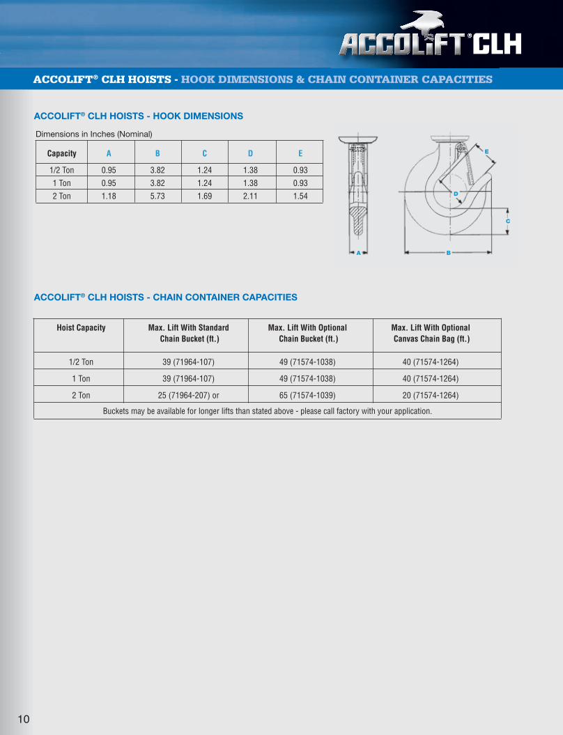
ACCOLIFT® CLH HOISTS - HOOK DIMENSIONS & CHAIN CONTAINER CAPACITIES
Dimensions in Inches (Nominal)
Capacity A B C D E
1/2 Ton 0.95 3.82 1.24 1.38 0.93
1 Ton 0.95 3.82 1.24 1.38 0.93
2 Ton 1.18 5.73 1.69 2.11 1.54
A B
C
E
D
Hoist Capacity Max. Lift With Standard Max. Lift With Optional Max. Lift With OptionalChain Bucket (ft.) Chain Bucket (ft.) Canvas Chain Bag (ft.)
1/2 Ton 39 (71964-107) 49 (71574-1038) 40 (71574-1264)
1 Ton 39 (71964-107) 49 (71574-1038) 40 (71574-1264)
2 Ton 25 (71964-207) or 65 (71574-1039) 20 (71574-1264)
Buckets may be available for longer lifts than stated above - please call factory with your application.
ACCOLIFT® CLH HOISTS - HOOK DIMENSIONS
ACCOLIFT® CLH HOISTS - CHAIN CONTAINER CAPACITIES
10
36518_Combo Cat_.qxp_Layout 1 6/21/17 7:43 AM Page 11

Weston Style Mechanical Load BrakeWeston Style Mechanical Load Brake,working in conjunction with disc type motorbrake, provides a dual braking system for loadlowering control. Mechanical Load Brake caneasily be inspected thru the inspection portprovided on the top of the gearbox.
Hoist Motor BrakeHoist motor brake is a direct acting DCrectified brake with exceptional stoppingpower providing cooler operatingtemperatures for the motor. Electric brake isdesigned for easy access and simplemaintenance.
Overload AlertOverload Alert is a current sensing device thatstops the up motion of the hoist and sets offan audible alarm when the hoist motor drawstoo many amps due to an overload condition.When the hoist is lowered, the alarm stopsand the overload device is reset.
Push Button ControlCompact design to enable one-handedoperation. Rated NEMA 4 protection.Mushroom on/off button included. Push buttoncable has strain relief built in to prevent cabledamage.
Electric Control PanelSingle speed hoists are reconnectable for208/230/460V power supply. Controls arehoused in a NEMA12 enclosure. Standardcontrol transformer output is 115V with anoption available for 48V. Standard powersupply cord length is 15'.
Variable Frequency DriveVFD hoists are available programmed for 2-speed operation. VFD hoists can be suppliedfor 230-1-60, 208/230-3-60 and 460-3-60power supplies. Inverter provides run time formaintenance operations.
Heavy-Duty Hoist MotorThe hoist motor is a high torque design and israted 30-minute duty. Class F motor insulationand standard thermal motor protection isincluded.
Load Sheave / Chain GuideFull floating chain guide assures properengagement of chain on load sheave. LoadSheave features 4 or 5 pockets (depending onmodel) for better distribution of the load.
®
ACCOLIFT® HOISTS - FEATURES
11
Load ChainGrade 80 load chain is case hardenedand has a high resistance to wear andcorrosion. All hoists are stocked with 20feet of lift. Longer lifts are available perrequirement. Nickel Plated load chainand Stainless Steel load chain is availableas an option.
HooksLoad hook is a forged carbon steel hookwith a heavy-duty hook latch. Thrustbearing in load hook allows 360˚ rotationto prevent twisting of load chain. Tophook, for hook suspended hoists, isnonrotating. Bullard hooks, StainlessSteel hooks and Bronze hooks areavailable for some models as an option.Contact factory.
Chain ContainerChain container is standard equipmentand is either molded with thickpolypropylene material or fabricated fromsteel to securely contain the chain andchain lubricant. Optional canvascontainers and engineered containers forlong lift applications are available as anoption.
Gear Box / Oil LubricationThe gearbox utilizes an alloy steel helicaland spur gear reduction. An access portis included on the top of the gear box toallow visual inspection of the mechanicalload brake. Lubrication is easilymaintained from the top of the hoist.
Push / Pull Trolley Trolley is adjustable for a range of 3.25”to 12” flange widths with no additionalmaterials required. Side guide rollers areincluded to promote smooth trolley motionand to minimize wheel and beam wear.Wheels are dual tread design foroperation on tapered or flat flange beams.Trolleys include drop down lugs andrubber bumpers as standard equipment.
Motorized Trolley Trolley is adjustable for a range of 3.25”*to 12” flange widths with no additionalmaterials required. Side guide rollers areincluded to promote smooth trolley motionand to minimize wheel and beam wear.Wheels are dual tread design foroperation on tapered or flat flange beams.Trolleys include drop down lugs andrubber bumpers as standard equipment.Trolley motor includes class F insulationand a disc type motor brake. Motor israted for 30-minute duty and includesstandard thermal motor protection.* 5" to 12" on 7-1/2T model.
36518_Combo Cat_.qxp_Layout 1 6/21/17 7:43 AM Page 12

INVERTER CONTROL HOOK SUSPENSION
1 2130030-VFD 20 18 21/7 2.4 9.2/8.4 4.2 .280 x (1) 0.75 165
2 2130050-VFD 20 18 21/7 4.7 18.4/16.8 7.9 .441 x (1) 1.84 282
3 2130060-VFD 20 18 15/5 4.7 18.4/16.8 7.9 .374 x (2) 2.62 337
3 2130060-VFD-230-1 20 18 15/5 4.7 18.4/16.8 - .374 x (2) 2.62 337
3 2130065-VFD 20 18 21/7 4.7 18.4/16.8 7.9 .441 x (1) 1.84 286
5 2130070-VFD 20 18 11/4 4.7 18.4/16.8 7.9 .441 x (2) 3.68 384
7.5 2130075-VFD 20 18 7/3 4.7 18.4/16.8 7.9 .441 x (3) 5.52 536
10 2130080-VFD 20 18 11/4 4.7 x (2) 34.4/31.6 15.8 .441 x (4) 7.36 964
15 2130090-VFD 20 18 7/3 4.7 x (2) 34.4/31.6 15.8 .441 x (6) 11.04 1786
20 2130095-VFD 20 18 6/2 4.7 x (2) 34.4/31.6 15.8 .441 x (8) 14.72 2030
ACCOLIFT® HOISTS - HOOK SUSPENSION
®
SINGLE SPEED HOOK SUSPENSION
1 2130020 20 18 17 2.0 8.8/8.0 4.0 .280 x (1) 0.75 165
1 2130030 20 18 27 2.4 9.2/8.4 4.2 .280 x (1) 0.75 165
2 2130040 20 18 13 2.4 9.2/8.4 4.2 .280 x (2) 1.5 198
2 2130050 20 18 27 4.7 17.2/15.8 7.9 .441 x (1) 1.84 282
3 2130060 20 18 17 4.7 17.2/15.8 7.9 .374 x (2) 2.62 337
3 2130065 20 18 21 4.7 17.2/15.8 7.9 .441 x (1) 1.84 286
5 2130070 20 18 11 4.7 17.2/15.8 7.9 .441 x (2) 3.68 384
7.5 2130075 20 18 7 4.7 17.2/15.8 7.9 .441 x (3) 5.52 536
10 2130080 20 18 11 4.7 x (2) 34.4/31.6 15.8 .441 x (4) 7.36 964
15 2130090 20 18 7 4.7 x (2) 34.4/31.6 15.8 .441 x (6) 11.04 1786
20 2130095 20 18 6 4.7 x (2) 34.4/31.6 15.8 .441 x (8) 14.72 2030
Add’l1 ft. of
Lift(lbs.)
Net Wt.(lbs.)
Load ChainDiameter (in.)
XChain Fall
Lines
Amp. Draw
Hoist Motor
460V208/230V
HP
LiftingSpeed(fpm)
PushButtonCord
Length(ft.)
Std.Lift (ft.)
Model Number
Cap.(Tons)
Add’l1 ft. of
Lift(lbs.)
Net Wt.(lbs.)
Load ChainDiameter (in.)
XChain Fall
Lines
Amp. Draw
Hoist Motor
460V208/230V
HP
LiftingSpeed(fpm)
PushButtonCord
Length(ft.)
Std.Lift (ft.)
Model Number
Cap.(Tons)
12
20 18
20 18
36518_Combo Cat_.qxp_Layout 1 6/21/17 7:43 AM Page 13
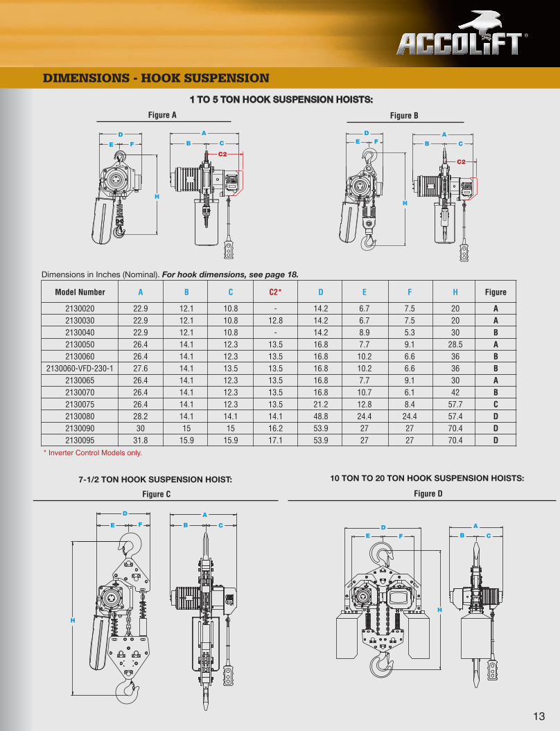
1 TO 5 TON HOOK SUSPENSION HOISTS:
Figure A Figure B
ED
E F
DF
HH
A
B
C2
C
A
B C
C2
Dimensions in Inches (Nominal). For hook dimensions, see page 18.
Model Number A B C C2* D E F H Figure
2130020 22.9 12.1 10.8 - 14.2 6.7 7.5 20 A2130030 22.9 12.1 10.8 12.8 14.2 6.7 7.5 20 A2130040 22.9 12.1 10.8 - 14.2 8.9 5.3 30 B2130050 26.4 14.1 12.3 13.5 16.8 7.7 9.1 28.5 A2130060 26.4 14.1 12.3 13.5 16.8 10.2 6.6 36 B
2130060-VFD-230-1 27.6 14.1 13.5 13.5 16.8 10.2 6.6 36 B2130065 26.4 14.1 12.3 13.5 16.8 7.7 9.1 30 A2130070 26.4 14.1 12.3 13.5 16.8 10.7 6.1 42 B2130075 26.4 14.1 12.3 13.5 21.2 12.8 8.4 57.7 C2130080 28.2 14.1 14.1 14.1 48.8 24.4 24.4 57.4 D2130090 30 15 15 16.2 53.9 27 27 70.4 D2130095 31.8 15.9 15.9 17.1 53.9 27 27 70.4 D
E FD
H
A
B C
10 TON TO 20 TON HOOK SUSPENSION HOISTS:
Figure D
E F
D
H
A
B C
7-1/2 TON HOOK SUSPENSION HOIST:
Figure C
13
®
DIMENSIONS - HOOK SUSPENSION
* Inverter Control Models only.
36518_Combo Cat_.qxp_Layout 1 6/21/17 7:43 AM Page 14

ACCOLIFT® HOISTS - PUSH / PULL TROLLEY
®
SINGLE SPEED PUSH / PULL TROLLEY
1 2130020-PT 20 18 17 2.0 8.8/8.0 4.0 3.25 to 12 3.7 32 .280 x (1) 0.75 174
1 2130030-PT 20 18 27 2.4 9.2/8.4 4.2 3.25 to 12 3.7 32 .280 x (1) 0.75 174
2 2130040-PT 20 18 13 2.4 9.2/8.4 4.2 3.25 to 12 4.3 32 .280 x (2) 1.5 229
2 2130050-PT 20 18 27 4.7 17.2/15.8 7.9 3.25 to 12 4.3 32 .441 x (1) 1.84 260
3 2130060-PT 20 18 17 4.7 17.2/15.8 7.9 3.25 to 12 4.9 40 .374 x (2) 2.62 404
3 2130065-PT 20 18 21 4.7 17.2/15.8 7.9 3.25 to 12 4.9 40 .441 x (1) 1.84 293
5 2130070-PT 20 18 11 4.7 17.2/15.8 7.9 3.25 to 12 5.5 72* .441 x (2) 3.68 523
Cap.(Tons)
Std.Lift(ft.)
PushButtonCord
Length(ft.)
LiftingSpeed(fpm) HP 460V
Flange Width
Adjustability(in.)
Min.BeamRadius(in.)
WheelDiameter
Load ChainDiameter
(in.) XChain Fall
Lines
NetWt.
(lbs.)
Add’l1 ft. of
Lift(lbs.)
ModelNumber
Hoist Motor
Amp. Draw
INVERTER CONTROL PUSH / PULL TROLLEY
1 2130030-VFD-PT 20 18 21/7 2.4 9.2/8.4 4.2 3.25 to 12 3.7 32 .280 x (1) 0.75 174
2 2130050-VFD-PT 20 18 21/7 4.7 17.2/15.8 7.9 3.25 to 12 4.3 32 .441 x (1) 1.84 260
3 2130060-VFD-PT 20 18 15/5 4.7 17.2/15.8 7.9 3.25 to 12 4.9 40 .374 x (2) 2.62 404
3 2130060-VFD-230-1-PT 20 18 15/5 4.7 17.2/15.8 - 3.25 to 12 4.9 40 .374 x (2) 2.62 404
3 2130065-VFD-PT 20 18 21/7 4.7 17.2/15.8 7.9 3.25 to 12 4.9 40 .441 x (1) 1.84 293
5 2130070-VFD-PT 20 18 11/4 4.7 17.2/15.8 7.9 3.25 to 12 5.5 72* .441 x (2) 3.68 523
Cap.(Tons)
Std.Lift(ft.)
PushButtonCord
Length(ft.)
LiftingSpeed(fpm) HP 460V
Flange Width
Adjustability(in.)
Min.BeamRadius(in.)
Load ChainDiameter
(in.) XChain Fall
Lines
NetWt.
(lbs.)
Add’l1 ft. of
Lift(lbs.)
ModelNumber
Hoist Motor
Amp. Draw
14
* Applies to a beam flange width of 4" and over.
WheelDiameter
20 18
20 18
208/230V
208/230V
36518_Combo Cat_.qxp_Layout 1 6/21/17 7:43 AM Page 15
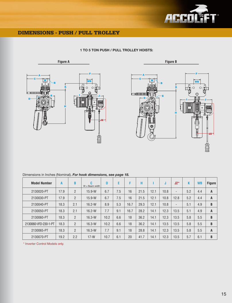
Dimensions in Inches (Nominal). For hook dimensions, see page 18.
Model Number A B C D E F H I J J2* K WB Figure
2130020-PT 17.9 2 15.9-W 6.7 7.5 16 21.5 12.1 10.8 - 5.2 4.4 A
2130030-PT 17.9 2 15.9-W 6.7 7.5 16 21.5 12.1 10.8 12.8 5.2 4.4 A
2130040-PT 18.3 2.1 16.2-W 8.9 5.3 16.7 29.3 12.1 10.8 - 5.1 4.9 B
2130050-PT 18.3 2.1 16.2-W 7.7 9.1 16.7 28.2 14.1 12.3 13.5 5.1 4.9 A
2130060-PT 18.3 2 16.3-W 10.2 6.6 18 36.2 14.1 12.3 13.5 5.8 5.5 B
2130060-VFD-230-1-PT 18.3 2 16.3-W 10.2 6.6 18 36.2 14.1 13.5 13.5 5.8 5.5 B
2130065-PT 18.3 2 16.3-W 7.7 9.1 18 28.8 14.1 12.3 13.5 5.8 5.5 A
2130070-PT 19.2 2.2 17-W 10.7 6.1 20 41.7 14.1 12.3 13.5 5.7 6.1 B
* Inverter Control Models only.
W = Beam width
®
DIMENSIONS - PUSH / PULL TROLLEY
A
B
C
F
I JD
E
K
H
J2
Figure A Figure B
W
1 TO 5 TON PUSH / PULL TROLLEY HOISTS:
15
E
J2
A
C
F
I JD
K
H
WB
WB WB
36518_Combo Cat_.qxp_Layout 1 6/21/17 7:43 AM Page 16
ACCOLIFT® HOISTS - MOTORIZED TROLLEY
®
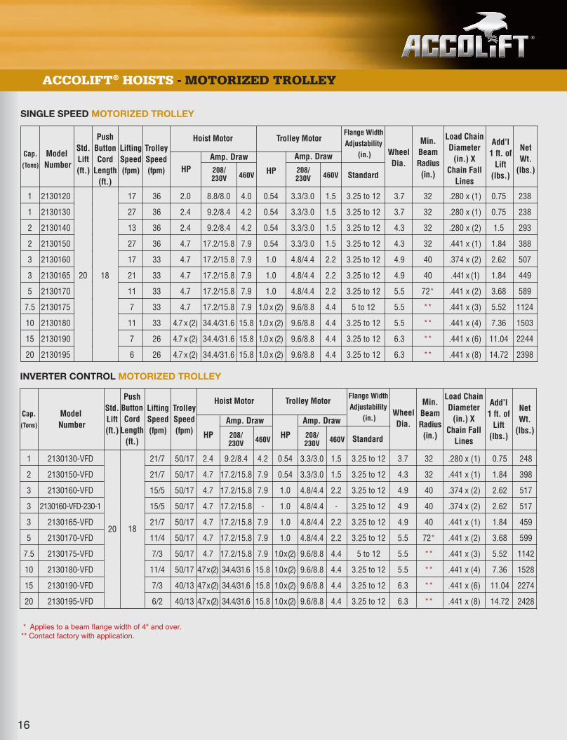
SINGLE SPEED MOTORIZED TROLLEY
1 2130120 20 18 17 36 2.0 8.8/8.0 4.0 0.54 3.3/3.0 1.5 3.25 to 12 3.7 32 .280 x (1) 0.75 238
1 2130130 20 18 27 36 2.4 9.2/8.4 4.2 0.54 3.3/3.0 1.5 3.25 to 12 3.7 32 .280 x (1) 0.75 238
2 2130140 20 18 13 36 2.4 9.2/8.4 4.2 0.54 3.3/3.0 1.5 3.25 to 12 4.3 32 .280 x (2) 1.5 293
2 2130150 20 18 27 36 4.7 17.2/15.8 7.9 0.54 3.3/3.0 1.5 3.25 to 12 4.3 32 .441 x (1) 1.84 388
3 2130160 20 18 17 33 4.7 17.2/15.8 7.9 1.0 4.8/4.4 2.2 3.25 to 12 4.9 40 .374 x (2) 2.62 507
3 2130165 20 18 21 33 4.7 17.2/15.8 7.9 1.0 4.8/4.4 2.2 3.25 to 12 4.9 40 .441 x (1) 1.84 449
5 2130170 20 18 11 33 4.7 17.2/15.8 7.9 1.0 4.8/4.4 2.2 3.25 to 12 5.5 72* .441 x (2) 3.68 589
7.5 2130175 20 18 7 33 4.7 17.2/15.8 7.9 1.0 x (2) 9.6/8.8 4.4 5 to 12 5.5 ** .441 x (3) 5.52 1124
10 2130180 20 18 11 33 4.7 x (2) 34.4/31.6 15.8 1.0 x (2) 9.6/8.8 4.4 3.25 to 12 5.5 ** .441 x (4) 7.36 1503
15 2130190 20 18 7 26 4.7 x (2) 34.4/31.6 15.8 1.0 x (2) 9.6/8.8 4.4 3.25 to 12 6.3 ** .441 x (6) 11.04 2244
20 2130195 20 18 6 26 4.7 x (2) 34.4/31.6 15.8 1.0 x (2) 9.6/8.8 4.4 3.25 to 12 6.3 ** .441 x (8) 14.72 2398
Cap.
(Tons)
Std.Lift(ft.)
PushButtonCord
Length(ft.)
LiftingSpeed(fpm)
TrolleySpeed(fpm) HP
460V HP 460V Standard
Min.BeamRadius(in.)
WheelDia.
Load ChainDiameter
(in.) XChain Fall
Lines
NetWt.
(lbs.)
Add’l1 ft. of
Lift(lbs.)
ModelNumber
Hoist Motor Trolley Motor
Amp. Draw Amp. Draw
INVERTER CONTROL MOTORIZED TROLLEY
1 2130130-VFD 20 18 21/7 50/17 2.4 9.2/8.4 4.2 0.54 3.3/3.0 1.5 3.25 to 12 3.7 32 .280 x (1) 0.75 248
2 2130150-VFD 20 18 21/7 50/17 4.7 17.2/15.8 7.9 0.54 3.3/3.0 1.5 3.25 to 12 4.3 32 .441 x (1) 1.84 398
3 2130160-VFD 20 18 15/5 50/17 4.7 17.2/15.8 7.9 1.0 4.8/4.4 2.2 3.25 to 12 4.9 40 .374 x (2) 2.62 517
3 2130160-VFD-230-1 20 18 15/5 50/17 4.7 17.2/15.8 - 1.0 4.8/4.4 - 3.25 to 12 4.9 40 .374 x (2) 2.62 517
3 2130165-VFD 20 18 21/7 50/17 4.7 17.2/15.8 7.9 1.0 4.8/4.4 2.2 3.25 to 12 4.9 40 .441 x (1) 1.84 459
5 2130170-VFD 20 18 11/4 50/17 4.7 17.2/15.8 7.9 1.0 4.8/4.4 2.2 3.25 to 12 5.5 72* .441 x (2) 3.68 599
7.5 2130175-VFD 20 18 7/3 50/17 4.7 17.2/15.8 7.9 1.0 x (2) 9.6/8.8 4.4 5 to 12 5.5 ** .441 x (3) 5.52 1142
10 2130180-VFD 20 18 11/4 50/17 4.7 x (2) 34.4/31.6 15.8 1.0 x (2) 9.6/8.8 4.4 3.25 to 12 5.5 ** .441 x (4) 7.36 1528
15 2130190-VFD 20 18 7/3 40/13 4.7 x (2) 34.4/31.6 15.8 1.0 x (2) 9.6/8.8 4.4 3.25 to 12 6.3 ** .441 x (6) 11.04 2274
20 2130195-VFD 20 18 6/2 40/13 4.7 x (2) 34.4/31.6 15.8 1.0 x (2) 9.6/8.8 4.4 3.25 to 12 6.3 ** .441 x (8) 14.72 2428
Cap.
(Tons)
Std.Lift(ft.)
PushButtonCord
Length(ft.)
LiftingSpeed(fpm)
TrolleySpeed(fpm) HP 208/
230V208/230V 460V HP 460V Standard
Min.BeamRadius(in.)
Load ChainDiameter
(in.) XChain Fall
Lines
NetWt.
(lbs.)
Add’l1 ft. of
Lift(lbs.)
ModelNumber
Hoist Motor Trolley Motor
Amp. Draw Amp. Draw
16
* Applies to a beam flange width of 4" and over.** Contact factory with application.
Flange WidthAdjustability
(in.)
Flange WidthAdjustability
(in.)
WheelDia.
20 18
20 18
208/230V
208/230V
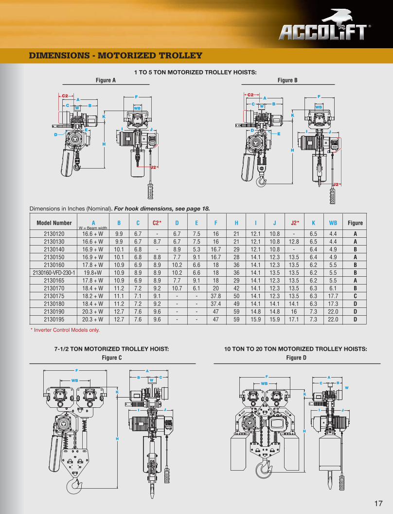
36518_Combo Cat_.qxp_Layout 1 6/21/17 7:43 AM Page 17
®
E
DIMENSIONS - MOTORIZED TROLLEY
ABC
ABC
F F
I J I JD
DE
K K
HH
J2
Dimensions in Inches (Nominal). For hook dimensions, see page 18.
Model Number A B C C2* D E F H I J J2* K WB Figure
2130120 16.6 + W 9.9 6.7 - 6.7 7.5 16 21 12.1 10.8 - 6.5 4.4 A2130130 16.6 + W 9.9 6.7 8.7 6.7 7.5 16 21 12.1 10.8 12.8 6.5 4.4 A2130140 16.9 + W 10.1 6.8 - 8.9 5.3 16.7 29 12.1 10.8 - 6.4 4.9 B2130150 16.9 + W 10.1 6.8 8.8 7.7 9.1 16.7 28 14.1 12.3 13.5 6.4 4.9 A2130160 17.8 + W 10.9 6.9 8.9 10.2 6.6 18 36 14.1 12.3 13.5 6.2 5.5 B
2130160-VFD-230-1 19.8+W 10.9 8.9 8.9 10.2 6.6 18 36 14.1 13.5 13.5 6.2 5.5 B2130165 17.8 + W 10.9 6.9 8.9 7.7 9.1 18 29 14.1 12.3 13.5 6.2 5.5 A2130170 18.4 + W 11.2 7.2 9.2 10.7 6.1 20 42 14.1 12.3 13.5 6.3 6.1 B2130175 18.2 + W 11.1 7.1 9.1 - - 37.8 50 14.1 12.3 13.5 6.3 17.7 C2130180 18.4 + W 11.2 7.2 9.2 - - 37.4 49 14.1 14.1 14.1 6.3 17.3 D2130190 20.3 + W 12.7 7.6 9.6 - - 47 59 14.8 14.8 16 7.3 22.0 D2130195 20.3 + W 12.7 7.6 9.6 - - 47 59 15.9 15.9 17.1 7.3 22.0 D
* Inverter Control Models only.
W = Beam width
Figure A Figure B
Figure D
JI
F
W
A
CB
Figure C
K
H
W WB WBW
17
1 TO 5 TON MOTORIZED TROLLEY HOISTS:
10 TON TO 20 TON MOTORIZED TROLLEY HOISTS:7-1/2 TON MOTORIZED TROLLEY HOIST:
C2 C2
J2
JI
F
W
A
BC
K
H
WBWB
36518_Combo Cat_.qxp_Layout 1 6/21/17 7:43 AM Page 18

®
18
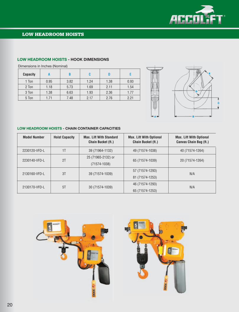
ACCOLIFT® HOISTS - HOOK DIMENSIONS & CHAIN CONTAINER CAPACITIES
Dimensions in Inches (Nominal)
Capacity A B C D E
1 Ton 0.95 3.82 1.24 1.38 .93
2 Ton 1.18 5.73 1.69 2.11 1.54
3 Ton 1.38 6.63 1.93 2.36 1.77
5 Ton 1.71 7.48 2.17 2.76 2.21
7 1/2 Ton 2.17 9.21 3.43 3.54 3.05
10 Ton 3.15 12.72 4.65 4.72 3.35
15 Ton 3.15 12.72 4.65 4.72 3.35
20 Ton 3.15 12.72 4.65 4.72 3.35
ACCOLIFT® HOISTS - HOOK DIMENSIONS
Model Number Hoist Capacity Max. Lift With Standard Max. Lift With Optional Max. Lift With OptionalChain Bucket (ft.) Chain Bucket (ft.) Canvas Chain Bag (ft.)
2130020 49 (71574-1038) 130 (71574-1039) 40 (71574-1264)2130120
1T (17 FPM)
2130030 49 (71574-1038) 130 (71574-1039) 40 (71574-1264)2130130
1T (27 FPM)
2130040 24 (71574-1038) 65 (71574-1039) 20 (71574-1264)2130140
2T (13 FPM)
2130050 20 (71574-1038) 59 (71574-1039) 15 (71574-1264)2130150
2T (27 FPM)
57 (71574-1293)2130060 39 (71574-1039) N/A2130160
3T (17 FPM)81 (71574-1253)
2130065 20 (71574-1038) 59 (71574-1039) 15 (71574-1264)2130165
3T (21 FPM)
46 (71574-1293)2130070 5T (11 FPM) 30 (71574-1039) N/A2130170 65 (71574-1253)
2130075 20 (71574-1039) 49 (71574-7239) N/A2130175
7.5T (7 FPM)
2130080 49 (71574-6239) 59 (71574-6239-2) N/A2130180
10T (11 FPM)
Steel buckets may be available for longer lifts than stated above - please call factory with your application.Buckets custom designed for 15T & 20T hoists as application requires.
ACCOLIFT® HOISTS - CHAIN CONTAINER CAPACITIES
A B
C
E
D
36518_Combo Cat_.qxp_Layout 1 6/21/17 7:43 AM Page 19
®
19
LOW HEADROOM HOISTS
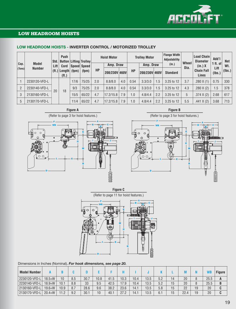
LOW HEADROOM HOISTS - INVERTER CONTROL / MOTORIZED TROLLEY
1 2230120-VFD-L 20 18 17/6 75/25 2.0 8.8/8.0 4.0 0.54 3.3/3.0 1.5 3.25 to 12 3.7 .280 X (1) 0.75 330
2 2230140-VFD-L 9/3 75/25 2.0 8.8/8.0 4.0 0.54 3.3/3.0 1.5 3.25 to 12 4.3 .280 X (2) 1.5 378
3 2130160-VFD-L 15/5 65/22 4.7 17.2/15.8 7.9 1.0 4.8/4.4 2.2 3.25 to 12 5 .374 X (2) 2.68 617
5 2130170-VFD-L 11/4 65/22 4.7 17.2/15.8 7.9 1.0 4.8/4.4 2.2 3.25 to 12 5.5 .441 X (2) 3.68 713
Cap.
(Tons)
Std.Lift(ft.)
PushButtonCord
Length(ft.)
LiftingSpeed(fpm)
TrolleySpeed(fpm) HP
208/230V 460V HP 208/230V 460V Standard
WheelDia.
Load ChainDiameter
(in.) XChain Fall
Lines
NetWt.
(lbs.)
Add’l1 ft. of
Lift(lbs.)
ModelNumber
Hoist Motor Trolley Motor
Amp. Draw Amp. Draw
Flange WidthAdjustability
(in.)
1820
Dimensions in Inches (Nominal). For hook dimensions, see page 20.
Model Number A B C D E F H I J K L M N WB Figure
2230120-VFD-L 18.5+W 10 8.5 30.7 10.8 41.5 10.3 10.4 13.5 5.2 14 20 8 25.5 A2230140-VFD-L 18.9+W 10.1 8.8 33 9.5 42.5 17.9 10.4 13.5 5.2 15 20 8 25.5 B2130160-VFD-L 19.6+W 10.9 8.7 28.6 9.6 38.2 23.6 14.1 13.5 5.8 15 22 19 20 C2130170-VFD-L 20.4+W 11.2 9.2 30.1 10 40.1 27.2 14.1 13.5 6.1 15 22.4 19 20 C
Figure A Figure B
Figure C
F
F AB C
A
WB
K
H
H
M
M
N
N
K
H
M
N
CA
WB C
I J I J
I J
L
L
L
D
D
D
E
E
E
WB
WB
F
WB
W
K
(Refer to page 3 for hoist features.) (Refer to page 3 for hoist features.)
(Refer to page 11 for hoist features.)
36518_Combo Cat_.qxp_Layout 1 6/21/17 7:43 AM Page 20
®
LOW HEADROOM HOISTS
LOW HEADROOM HOISTS - CHAIN CONTAINER CAPACITIES
20
Dimensions in Inches (Nominal)
Capacity A B C D E
1 Ton 0.95 3.82 1.24 1.38 0.93
2 Ton 1.18 5.73 1.69 2.11 1.54
3 Ton 1.38 6.63 1.93 2.36 1.77
5 Ton 1.71 7.48 2.17 2.76 2.21
A B
C
E
D
LOW HEADROOM HOISTS - HOOK DIMENSIONS
Model Number Hoist Capacity Max. Lift With Standard Max. Lift With Optional Max. Lift With OptionalChain Bucket (ft.) Chain Bucket (ft.) Canvas Chain Bag (ft.)
2230120-VFD-L 1T 39 (71964-1132) 49 (71574-1038) 40 (71574-1264)
2230140-VFD-L 2T25 (71965-2132) or
65 (71574-1039) 20 (71574-1264)(71574-1038)
2130160-VFD-L 3T 39 (71574-1039)57 (71574-1293)
N/A81 (71574-1253)
2130170-VFD-L 5T 30 (71574-1039)46 (71574-1293)
N/A65 (71574-1253)
36518_Combo Cat_.qxp_Layout 1 6/21/17 7:43 AM Page 21

21
SERIES 421 PUSH-PULL END TRUCKS
4210010 2 6” 1200 233
ModelNumber
Cap.(Tons)
Min. SizeRunwayBeam
Net Weight(lbs.)
Max. AllowableLoad on EachWheel (lbs.)
10 6” x 12.5# 2
1 15 8” x 18.4# 2-1/420 10” x 25.4# 2-3/425 12” x 31.8# 310 8” x 18.4# 2-1/4
2 15 10” x 25.4# 2-3/420 12” x 31.8# 325 15” x 42.9# 3-1/2
Capacity(Tons)
Span(Feet)
RecommendedBridge Beams
Crane Fabricating and Clearance Dimensions
Y(Inches)
Y
Warning: Only competent personnel familiar with standard fabricationpractices should be employed to assemble these cranes because of thenecessity of properly interpreting these instructions and for the purposes ofdetermining appropriate compatible equipment and product applications.ACCO disclaims and responsibility for the quality of workmanship employed inthe fabrication of a crane according to these instructions or the sufficiency ofthe system in which and to which this system or equipment is to be installed orthe sufficiency of the system to sustain any particular load that may beimposed upon it. Contact ACCO for additional information if necessary.
43-1/2” Overall Length
4-3/8”
2-3/8”4-9/16”
1-1/2”
1-3/4”1-3/4”Runway BeamFlange + 1-1/8”
Minimum Overhang
1/2” Min.
38” Wheelbase
Bridge Beam By Others
Runway By Others
For Underhung Single Girder Cranes
Designed for light or medium loads, Series 421 Push-Pull End Trucks are the basic component foreasy-to-assemble underhung cranes.
• Furnished with heat treated gray iron wheels for 2 ton maximum crane capacities.• Maximum crane span is 25’-0”.• End truck frames include drop lugs.• Wheels are 4" diameter, flanged, dual tread permittingoperation on standard "I" beams or flat flange beams.Wheels incorporate shielded, lifetime lubricated, singlerow ball bearings.• End trucks are shipped with crane fabrication instructionsand mounting hardware. Bridge beam and end stops areby others.
36518_Combo Cat_.qxp_Layout 1 6/21/17 7:43 AM Page 22
22
HAND CHAIN HOISTS
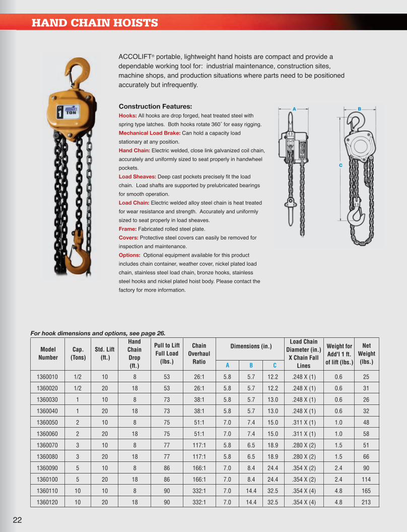
For hook dimensions and options, see page 26.
1360010 1/2 10 8 53 26:1 5.8 5.7 12.2 .248 X (1) 0.6 25
1360020 1/2 20 18 53 26:1 5.8 5.7 12.2 .248 X (1) 0.6 31
1360030 1 10 8 73 38:1 5.8 5.7 13.0 .248 X (1) 0.6 26
1360040 1 20 18 73 38:1 5.8 5.7 13.0 .248 X (1) 0.6 32
1360050 2 10 8 75 51:1 7.0 7.4 15.0 .311 X (1) 1.0 48
1360060 2 20 18 75 51:1 7.0 7.4 15.0 .311 X (1) 1.0 58
1360070 3 10 8 77 117:1 5.8 6.5 18.9 .280 X (2) 1.5 51
1360080 3 20 18 77 117:1 5.8 6.5 18.9 .280 X (2) 1.5 66
1360090 5 10 8 86 166:1 7.0 8.4 24.4 .354 X (2) 2.4 90
1360100 5 20 18 86 166:1 7.0 8.4 24.4 .354 X (2) 2.4 114
1360110 10 10 8 90 332:1 7.0 14.4 32.5 .354 X (4) 4.8 165
1360120 10 20 18 90 332:1 7.0 14.4 32.5 .354 X (4) 4.8 213
A B
C
ACCOLIFT® portable, lightweight hand hoists are compact and provide adependable working tool for: industrial maintenance, construction sites,machine shops, and production situations where parts need to be positionedaccurately but infrequently.
Construction Features:
Hooks: All hooks are drop forged, heat treated steel withspring type latches. Both hooks rotate 360˚ for easy rigging.Mechanical Load Brake: Can hold a capacity loadstationary at any position.Hand Chain: Electric welded, close link galvanized coil chain,accurately and uniformly sized to seat properly in handwheelpockets.Load Sheaves: Deep cast pockets precisely fit the loadchain. Load shafts are supported by prelubricated bearingsfor smooth operation.Load Chain: Electric welded alloy steel chain is heat treatedfor wear resistance and strength. Accurately and uniformlysized to seat properly in load sheaves.Frame: Fabricated rolled steel plate.Covers: Protective steel covers can easily be removed forinspection and maintenance.Options: Optional equipment available for this productincludes chain container, weather cover, nickel plated loadchain, stainless steel load chain, bronze hooks, stainlesssteel hooks and nickel plated hoist body. Please contact thefactory for more information.
ModelNumber
Cap.(Tons)
Std. Lift(ft.)
Pull to LiftFull Load
(lbs.)
Hand Chain Drop(ft.)
Dimensions (in.)Load Chain
Diameter (in.)X Chain Fall
Lines
Chain Overhaul
Ratio
Net Weight(lbs.)
Weight forAdd'l 1 ft.
of lift (lbs.)A B C
36518_Combo Cat_.qxp_Layout 1 6/21/17 7:43 AM Page 23

Dimensions in Inches (Nominal)
A B C D E F G
1650110 1/2 3” to 5” 18 10.8 9.1 5.1 1.8 3.2 1.1 4.8 5 30 35
1650120 1 3” to 5” 18 10.8 9.1 5.1 1.8 3.2 1.1 4.8 5 30 35
1650130 2 3” to 6” 18 12.0 10.6 6.1 2.4 3.9 1.4 5.6 6 36 57
1650140 3 3” to 6” 18 13.0 12.3 7.5 2.6 4.5 1.9 6.4 7 36 79
1650150 5 5” to 7” 18 15.0 13.9 9.1 3.0 4.9 2.1 7.2 10 48 114
1650160 10 5” to 7.5” 18 17.0 13.9 11.0 3.2 4.9 2.1 7.2 10 48 227
PLAIN TROLLEYS
GEARED TROLLEYS
Dimensions in Inches (Nominal)
A B C D E F G
1650010 1/2 3” to 5” 8.1 6.9 5.1 1.8 2.2 1.1 3.5 4 24 14
1650020 1 3” to 5” 8.1 9.1 5.1 1.8 3.2 1.1 4.8 5 30 22
1650030 2 3” to 6” 9.3 10.6 6.1 2.4 3.9 1.4 5.6 6 36 41
1650040 3 3” to 6” 9.9 12.3 7.5 2.6 4.5 1.9 6.4 7 36 63
1650050 5 5” to 7” 11.1 13.9 9.1 3.0 4.9 2.1 7.2 10 48 97
ACCOLIFT® Plain Trolleys are light and easy to adapt to a widerange of beams. The trolley wheels include lifetime lubricated ballbearings for maintenance free operation. A perfect match tomake the ACCOLIFT® electric or hand chain hoist and its loadhorizontally mobile.
WF
E
A
B
G
C
D
H
ModelNumber
Cap.(Tons)
WBeam Width
Min. - Max.
DimensionsMin.BeamSizeH
Min.BeamRadius
NetWeight(lbs.)
ModelNumber
Cap.(Tons)
WBeam Width
Min. - Max.
DimensionsMin.BeamSize
H
Min.BeamRadius
NetWeight(lbs.)
W
A
E
B
G
H
C
D
F
ACCOLIFT® Geared Trolleys are light and easy to adapt to awide range of beams. The trolley wheels include lifetimelubricated ball bearings for maintenance free operation. Aperfect match to make the ACCOLIFT® electric or hand chainhoist and its load horizontally mobile for short distances andaccurate load positioning.
Construction Features:
Side Frame: Side plates are rugged rolled steelWheels: Crown tread allows operation on tapered or flat flange beamsBearings: Shielded, lifetime lubricated, single row ball bearings.Suspension Lug: Pivot mounted suspension shaft designed to equally distribute the load to all wheels.Options: Optional equipment available for this product includes bronze wheels and nickel plated body.Please contact the factory for more information.
Construction Features:
Side Frame: Side plates are rugged rolled steelWheels: Crown tread allows operation on tapered or flat flange beamsBearings: Shielded, lifetime lubricated, single row ball bearings.Hand Chain: Electric welded, close link galvanized coil chain, accurately and uniformly sized to seat properly in handwheel pockets.Chain Guide: Steel chain guide.Suspension Lug: Pivot mounted suspension shaft designed to equally distribute the load to all wheels.Options: Optional equipment available for this product includes bronze wheels, stainless steel hand chain and nickel plated body.Please contact the factory for more information.
Hand Chain Drop(ft.)
23
36518_Combo Cat_.qxp_Layout 1 6/21/17 7:43 AM Page 24
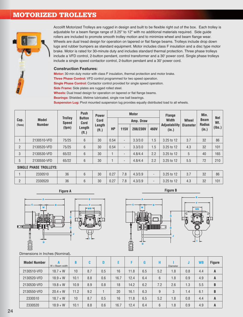
1 2130510-VFD 75/25 6 30 0.54 - 3.3/3.0 1.5 3.25 to 12 3.7 32 86
2 2130520-VFD 75/25 6 30 0.54 - 3.3/3.0 1.5 3.25 to 12 4.3 32 101
3 2130530-VFD 65/22 6 30 1 - 4.8/4.4 2.2 3.25 to 12 5 40 165
5 2130550-VFD 65/22 6 30 1 - 4.8/4.4 2.2 3.25 to 12 5.5 72 210
SINGLE PHASE TROLLEYS:
1 2330510 36 6 30 0.27 7.8 4.3/3.9 - 3.25 to 12 3.7 32 86
2 2330520 36 6 30 0.27 7.8 4.3/3.9 - 3.25 to 12 4.3 32 101
Amp. DrawCap.(Tons)
TrolleySpeed(fpm)
PushButtonCord
Length(ft.)
PowerCord
Length(ft.) HP 208/230V 460V115V
Flange Width
Adjustability(in.)
Min.BeamRadius(in.)
NetWt.
(lbs.)
ModelNumber
Motor
WheelDiameter
MOTORIZED TROLLEYS
Dimensions in Inches (Nominal).
Model Number A B C D E F G H I J WB Figure
2130510-VFD 18.7 + W 10 8.7 0.5 16 11.8 6.5 5.2 1.8 0.8 4.4 A
2130520-VFD 18.9 + W 10.1 8.8 0.6 16.7 12.4 6.4 6 1.8 0.9 4.9 A
2130530-VFD 19.8 + W 10.9 8.9 0.8 18 14.2 6.2 7.2 2.6 1.3 5.5 B
2130550-VFD 20.4 + W 11.2 9.2 1 20 16.1 6.3 9 3 1.4 6.1 B
2330510 18.7 + W 10 8.7 0.5 16 11.8 6.5 5.2 1.8 0.8 4.4 A
2330520 18.9 + W 10.1 8.8 0.6 16.7 12.4 6.4 6 1.8 0.9 4.9 A
W = Beam width Diameter
Accolift Motorized Trolleys are rugged in design and built to be flexible right out of the box. Each trolley isadjustable for a beam flange range of 3.25" to 12" with no additional materials required. Side guiderollers are included to promote smooth trolley motion and to minimize wheel and beam flange wear.Wheels are dual tread design for operation on tapered or flat flange beams. Trolleys include drop downlugs and rubber bumpers as standard equipment. Motor includes class F insulation and a disc type motorbrake. Motor is rated for 30-minute duty and includes standard thermal protection. Three phase trolleysinclude a VFD control, 2-button pendant, control transformer and a 30' power cord. Single phase trolleysinclude a single speed contactor control, 2-button pendant and a 30' power cord.
Construction Features:
Motor: 30-min duty motor with class F insulation, thermal protection and motor brake.Three Phase Control: VFD control programmed for two speed operation.Single Phase Control: Contactor control provided for single speed operation.Side Frame: Side plates are rugged rolled steel.Wheels: Dual tread design for operation on tapered or flat flange beams.Bearings: Shielded, lifetime lubricated, single row ball bearings.Suspension Lug: Pivot mounted suspension lug provides equally distributed load to all wheels.
C
A
J
D
H
G
BW
F
WB
E
I
C
A
J
D
H
G
BW
F
WB
E
I
24
Figure A Figure B
36518_Combo Cat_.qxp_Layout 1 6/21/17 7:43 AM Page 25

25
LEVER HOISTS
Lightweight, portable, chain type lever operated puller. Increases aworker's efficiency in pulling, lifting, lowering, moving and skidding objectsin industrial maintenance, construction and utility company applications.Minimal effort is required to move tons. The short handle and short strokeare designed to operate in tight places. Excellent for stretching cable andfencing, positioning machinery and building components.
AB
C
D
Frame/Side Plate: Rugged, lightweightsteel design supports and protects internalmechanism.Lever/Lever Block: Designed andconstructed to be easily operated by oneperson. Helps absorb the shock of theload. Can be easily disassembled formaintenance.Operation: Two levers and a knob controlthe operation of the ACCOLIFT® LeverHoist. The lifting "lock" lever can only beengaged when the hoist chain is slack (notunder load). The grip ring is then pulled toengage the load sheave. Choose "Up" or"Down" position on the handle to raise orlower the load.Gears: Six tooth pinion gear and fourpocket load sheave makes operation easy.Gears are permanently lubricated.
Mechanical Load Brake: Brake can holda full capacity load stationary in anyposition. Load is not transferred back tohandle during handle advancement.Load Chain: Electric welded alloy steelchain is heat treated for wear resistanceand strength. Accurately and uniformlysized to seat properly in load sheaves.Load Block: Supports the suspensionhook and allows it to rotate 360˚ undercapacity loads.Hooks: All hooks are drop forged, heattreated steel with spring type latches. Both hooks rotate 360˚ for easy rigging.
Construction Features:
For hook dimensions, see page 26.
1150010 3/4 5 35 5.9 5.0 11.4 9.4 .248 X (1) 0.6 16
1150110 3/4 10 35 5.9 5.0 11.4 9.4 .248 X (1) 0.6 19
1150210 3/4 15 35 5.9 5.0 11.4 9.4 .248 X (1) 0.6 22
1150020 1-1/2 5 40 6.5 5.8 13.4 14.2 .280 X (1) 0.8 22
1150120 1-1/2 10 40 6.5 5.8 13.4 14.2 .280 X (1) 0.8 26
1150220 1-1/2 15 40 6.5 5.8 13.4 14.2 .280 X (1) 0.8 30
1150030 3 5 73 7.6 7.1 16.9 14.2 .354 X (1) 1.2 36
1150040 6 5 77 7.6 7.1 22.4 14.2 .354 X (2) 2.4 60
ModelNumber
Cap.(Tons)
Std. Lift(ft.)
Pull to LiftFull Load
(lbs.)
Dimensions (in.)Load Chain
Diameter (in.)X Chain Fall
Lines
NetWeight(lbs.)
Weight forAdd'l 1 ft.
of lift (lbs.)A B C D
36518_Combo Cat_.qxp_Layout 1 6/21/17 7:43 AM Page 26
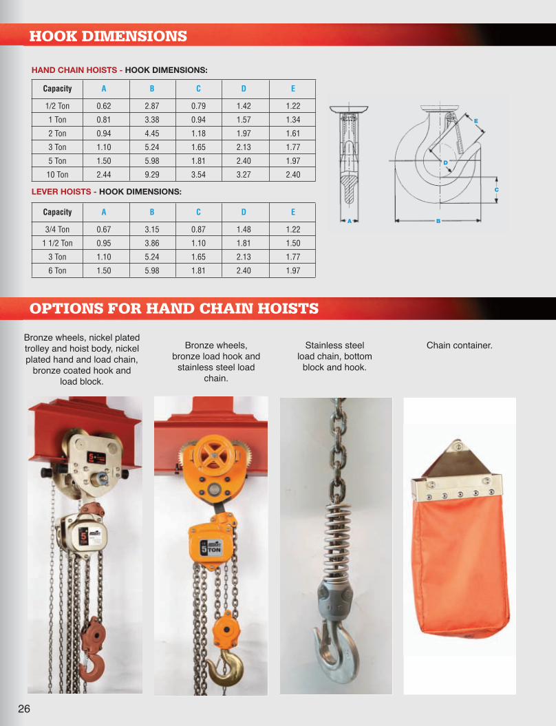
26
Capacity A B C D E
1/2 Ton 0.62 2.87 0.79 1.42 1.22
1 Ton 0.81 3.38 0.94 1.57 1.34
2 Ton 0.94 4.45 1.18 1.97 1.61
3 Ton 1.10 5.24 1.65 2.13 1.77
5 Ton 1.50 5.98 1.81 2.40 1.97
10 Ton 2.44 9.29 3.54 3.27 2.40
HAND CHAIN HOISTS - HOOK DIMENSIONS:
Capacity A B C D E
3/4 Ton 0.67 3.15 0.87 1.48 1.22
1 1/2 Ton 0.95 3.86 1.10 1.81 1.50
3 Ton 1.10 5.24 1.65 2.13 1.77
6 Ton 1.50 5.98 1.81 2.40 1.97
LEVER HOISTS - HOOK DIMENSIONS:
HOOK DIMENSIONS
A B
C
E
D
OPTIONS FOR HAND CHAIN HOISTS
Bronze wheels,bronze load hook andstainless steel load
chain.
Bronze wheels, nickel platedtrolley and hoist body, nickelplated hand and load chain,bronze coated hook and
load block.
Chain container.Stainless steelload chain, bottomblock and hook.
36518_Combo Cat_.qxp_Layout 1 6/21/17 7:43 AM Page 27
27
Call your Acco Material Handling sales professionaltoday and put the reliability of Accolift equipment to
work at your facility.
Robert Webb, Sales [email protected], All Provinces
Jeff Dawson, National Sales [email protected], Idaho, Wyoming, Mexico
Alan Hopes, District [email protected], Indiana, Kentucky, Ohio, West Virginia
Andrew Roy, District [email protected], Oklahoma
Keith McColm, District [email protected], California, Nevada, Utah, Oregon,
Washington, Colorado, New Mexico, Hawaii,
Alaska
John Jones, District [email protected] Dakota, South Dakota, Nebraska, Iowa, Missouri,
Illinois, Minnesota, Wisconsin, Kansas
Bill Burke, District [email protected], Virginia, New York, New Jersey, Maryland,
Vermont, New Hampshire, Maine, Connecticut,
Delaware, D.C., Massachusetts, Rhode Island
Greg Logan, District [email protected], Mississippi, Tennessee, Louisiana, North
Carolina, South Carolina, Georgia, Alabama, Florida
Learn more at:
www.AccoMHS.com
Canada
Mexico
36518_Combo Cat_.qxp_Layout 1 6/21/17 7:44 AM Page 28

ACCO Material Handling Solutions76 Acco Drive, Box 792, York, PA 17405-0792717-741-4863, 800-967-7333, FAX 800-715-8897E-mail: [email protected] www.accomhs.com
© 2017 ACCO Material Handling Solutions, Printed in the USABulletin PD2312
5/17
28
�
�
�
�
�
Ask about these top brand name products from ACCO Material Handling Solutions:
Wire rope hoists and crane componentsmanufactured in capacities from 1 to 25 tons.
Patented Track Cranes and Monorail Systems.
Below-the-hook lifters; both standard and custom engineered.
Industrial trailers and non-powered material handling equipment of all types.
Work-Rated Class 1, Groups C & D,Division 1 hoist monorail hoist.
Louden crane with SpeedWay hoist.
Link Caster Steer Industrial Trailer fortransporting cylinders.
WARNING: Equipment described herein is not designedfor, and should not be used for lifting, supporting, ortransporting humans. Modifications to upgrade, rerate, orotherwise alter the hoist or crane equipment shall beauthorized only by the original manufacturer or qualifiedprofessional engineer. Failure to comply with any one ofthe limitations noted herein may result in serious bodilyinjury.
WARRANTY: All equipment is covered by the followingwarranties: The Seller warrants to the original using Buyerthereof that the goods sold under this agreement are freefrom defects in workmanship and materials for a periodof one year from the date of shipment to the using Buyer.No other express warranties are given and no affirmationof Seller or Seller's agents, by word or action, shallconstitute a warranty. Any variations in details betweenthe goods quoted herein and those covered in Buyer'sspecifications are due to standards of manufacture not tobe construed as exceptions to the specifications.
36518_Combo Cat_.qxp_Layout 1 6/21/17 7:43 AM Page 1