Embed Size (px)
Citation preview
DOCUMENT TITLE: CHA Evaporator Operation 7/9/2009 AUTHORS: Roger Robbins, John Maynard Page 1 of 18
CHA-50 Evaporator Operation Roger Robbins 7/8/2009 John Maynard
The University of Texas at Dallas ERIK JONSSON SCHOOL OF ENGINEERING
DOCUMENT TITLE: CHA Evaporator Operation 7/9/2009 AUTHORS: Roger Robbins, John Maynard Page 2 of 18
CHA-50 Evaporator Operation Roger Robbins 7/8/2009 John Maynard C:\\MyDocuments\CleanRoomGeneral\Equipment\Evaporator-eGun\CHAmanual.doc
Table of Contents
CHA-50 EVAPORATOR OPERATION .......................................................................................................... 1
CHA-50 EVAPORATOR OPERATION .......................................................................................................... 2
TABLE OF CONTENTS .................................................................................................................................. 2
CHA EVAPORATOR OPERATION ............................................................................................................... 3
INTRODUCTION ......................................................................................................................................... 3 DESCRIPTION ........................................................................................................................................... 3
Evaporation Chamber System ........................................................................................................... 6 OPERATING INSTRUCTIONS .......................................................................................................................... 8
Vent & Load System ......................................................................................................................... 8 Evaporation Process ....................................................................................................................... 14
Setup Film thickness Monitor and Beam Control Parameters ...................................................................... 14 Establishing Electron Beam ........................................................................................................................ 15 Depositing Material ................................................................................................................................... 16
Unloading Samples ......................................................................................................................... 17
DOCUMENT TITLE: CHA Evaporator Operation 7/9/2009 AUTHORS: Roger Robbins, John Maynard Page 3 of 18
CHA-50 Evaporator Operation Roger Robbins 7/8/2009 John Maynard C:\\MyDocuments\CleanRoomGeneral\Equipment\Evaporator-eGun\CHAmanual.doc
Introduction
The CHA Evaporator is an electron beam metal evaporator with the capability of coating 24 six inch diameter wafers at a time. This tool is intended as a general purpose metal evaporator that will enhance step coverage by continuous modification of the landing angle of the evaporating metal atoms via a two axis revolution/rotation substrate holder system (planetary mount). This document will describe what the controls do and then describe how to run it.
Description The evaporator hardware consists of three major blocks; 1) Control electronics rack; 2)evaporator vacuum system containing the electron gun and evaporator crucibles with the substrates to be coated mounted on a rotating planetary system; 3) Electron beam control power and thickness measurement electronics. These three sections are shown in the first three figures along with labels pointing out key controls.
DOCUMENT TITLE: CHA Evaporator Operation 7/9/2009 AUTHORS: Roger Robbins, John Maynard Page 4 of 18
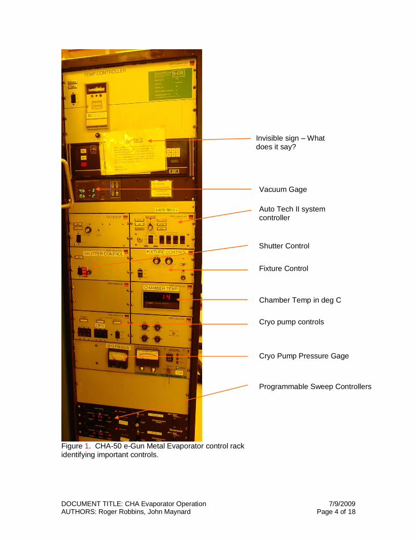
Figure 1. CHA-50 e-Gun Metal Evaporator control rack identifying important controls.
Auto Tech II controller
Vacuum Gage
Fixture Control
Shutter Control
Chamber Temp ? Chamber Temp in deg C
Cryo Pump Pressure Gage
Auto Tech II controller Auto Tech II system controller
Invisible sign – What does it say?
Cryo pump controls
Programmable Sweep Controllers
DOCUMENT TITLE: CHA Evaporator Operation 7/9/2009 AUTHORS: Roger Robbins, John Maynard Page 5 of 18
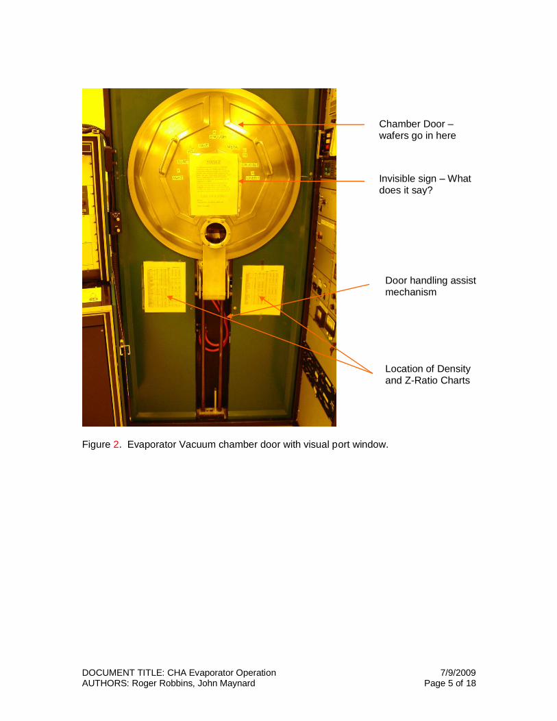
Figure 2. Evaporator Vacuum chamber door with visual port window.
Chamber Door – wafers go in here
Invisible sign – What does it say?
Door handling assist mechanism
Location of Density and Z-Ratio Charts
DOCUMENT TITLE: CHA Evaporator Operation 7/9/2009 AUTHORS: Roger Robbins, John Maynard Page 6 of 18
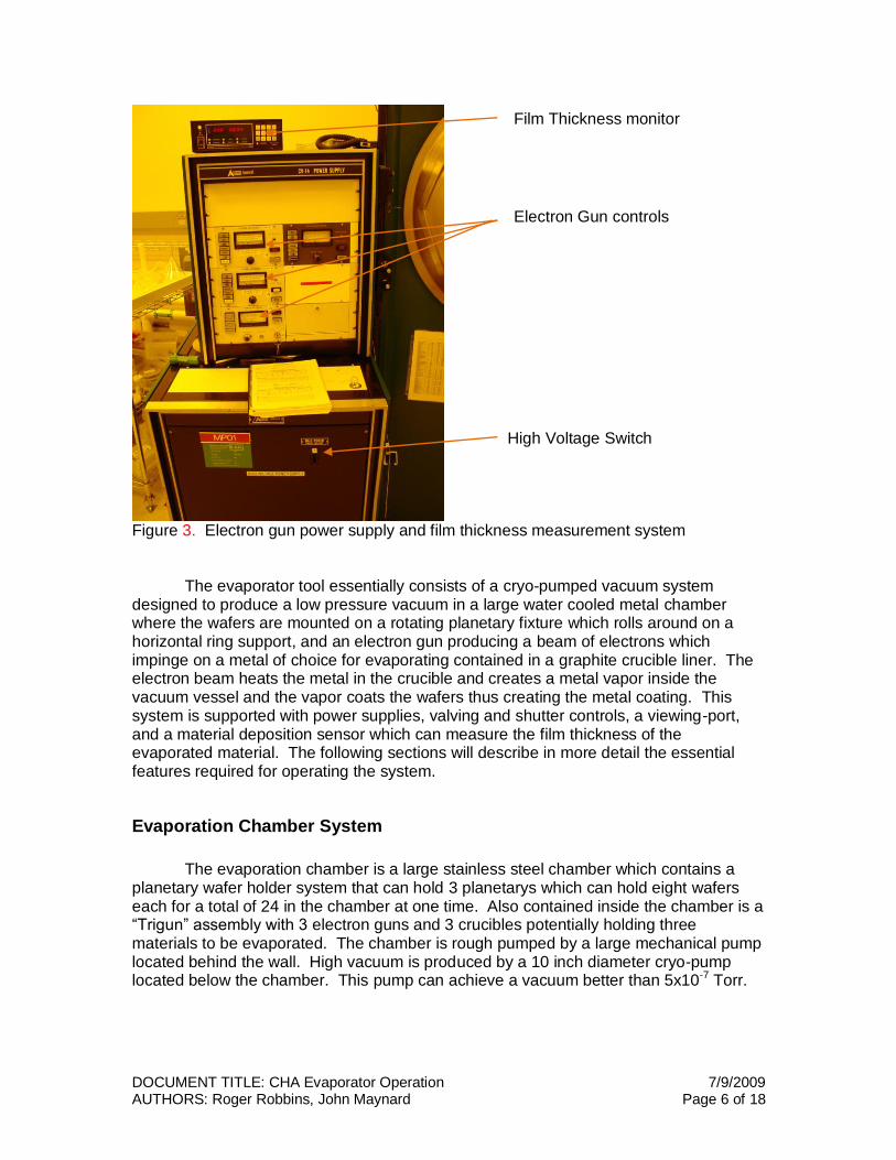
Figure 3. Electron gun power supply and film thickness measurement system The evaporator tool essentially consists of a cryo-pumped vacuum system designed to produce a low pressure vacuum in a large water cooled metal chamber where the wafers are mounted on a rotating planetary fixture which rolls around on a horizontal ring support, and an electron gun producing a beam of electrons which impinge on a metal of choice for evaporating contained in a graphite crucible liner. The electron beam heats the metal in the crucible and creates a metal vapor inside the vacuum vessel and the vapor coats the wafers thus creating the metal coating. This system is supported with power supplies, valving and shutter controls, a viewing-port, and a material deposition sensor which can measure the film thickness of the evaporated material. The following sections will describe in more detail the essential features required for operating the system.
Evaporation Chamber System
The evaporation chamber is a large stainless steel chamber which contains a planetary wafer holder system that can hold 3 planetarys which can hold eight wafers each for a total of 24 in the chamber at one time. Also contained inside the chamber is a “Trigun” assembly with 3 electron guns and 3 crucibles potentially holding three materials to be evaporated. The chamber is rough pumped by a large mechanical pump located behind the wall. High vacuum is produced by a 10 inch diameter cryo-pump located below the chamber. This pump can achieve a vacuum better than 5x10⁻⁷ Torr.
High Voltage Switch
Film Thickness monitor
Electron Gun controls
DOCUMENT TITLE: CHA Evaporator Operation 7/9/2009 AUTHORS: Roger Robbins, John Maynard Page 7 of 18
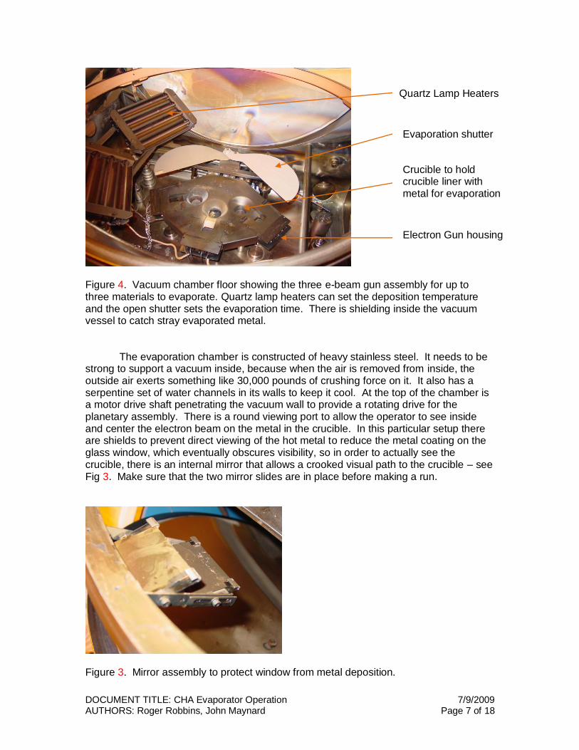
Figure 4. Vacuum chamber floor showing the three e-beam gun assembly for up to three materials to evaporate. Quartz lamp heaters can set the deposition temperature and the open shutter sets the evaporation time. There is shielding inside the vacuum vessel to catch stray evaporated metal. The evaporation chamber is constructed of heavy stainless steel. It needs to be strong to support a vacuum inside, because when the air is removed from inside, the outside air exerts something like 30,000 pounds of crushing force on it. It also has a serpentine set of water channels in its walls to keep it cool. At the top of the chamber is a motor drive shaft penetrating the vacuum wall to provide a rotating drive for the planetary assembly. There is a round viewing port to allow the operator to see inside and center the electron beam on the metal in the crucible. In this particular setup there are shields to prevent direct viewing of the hot metal to reduce the metal coating on the glass window, which eventually obscures visibility, so in order to actually see the crucible, there is an internal mirror that allows a crooked visual path to the crucible – see Fig 3. Make sure that the two mirror slides are in place before making a run.
Figure 3. Mirror assembly to protect window from metal deposition.
Quartz Lamp Heaters
Evaporation shutter
Crucible to hold crucible liner with metal for evaporation
Electron Gun housing
DOCUMENT TITLE: CHA Evaporator Operation 7/9/2009 AUTHORS: Roger Robbins, John Maynard Page 8 of 18
Operating Instructions
Vent & Load System
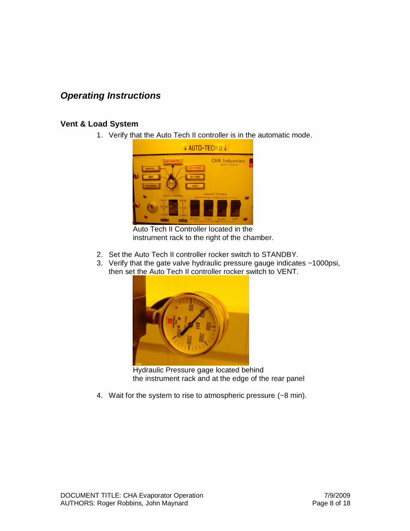
1. Verify that the Auto Tech II controller is in the automatic mode.
Auto Tech II Controller located in the instrument rack to the right of the chamber.
2. Set the Auto Tech II controller rocker switch to STANDBY. 3. Verify that the gate valve hydraulic pressure gauge indicates ~1000psi,
then set the Auto Tech II controller rocker switch to VENT.
Hydraulic Pressure gage located behind the instrument rack and at the edge of the rear panel
4. Wait for the system to rise to atmospheric pressure (~8 min).
DOCUMENT TITLE: CHA Evaporator Operation 7/9/2009 AUTHORS: Roger Robbins, John Maynard Page 9 of 18
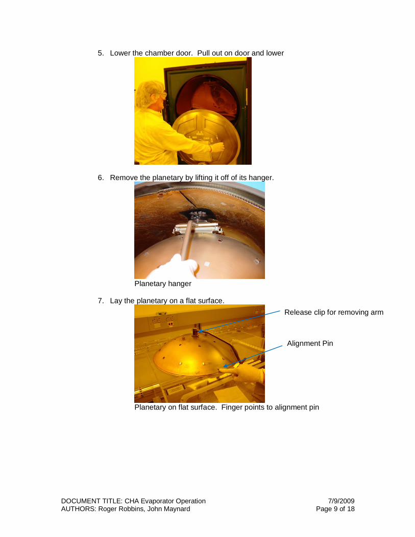
5. Lower the chamber door. Pull out on door and lower
6. Remove the planetary by lifting it off of its hanger.
Planetary hanger
7. Lay the planetary on a flat surface.
Planetary on flat surface. Finger points to alignment pin
Release clip for removing arm
Alignment Pin
DOCUMENT TITLE: CHA Evaporator Operation 7/9/2009 AUTHORS: Roger Robbins, John Maynard Page 10 of 18
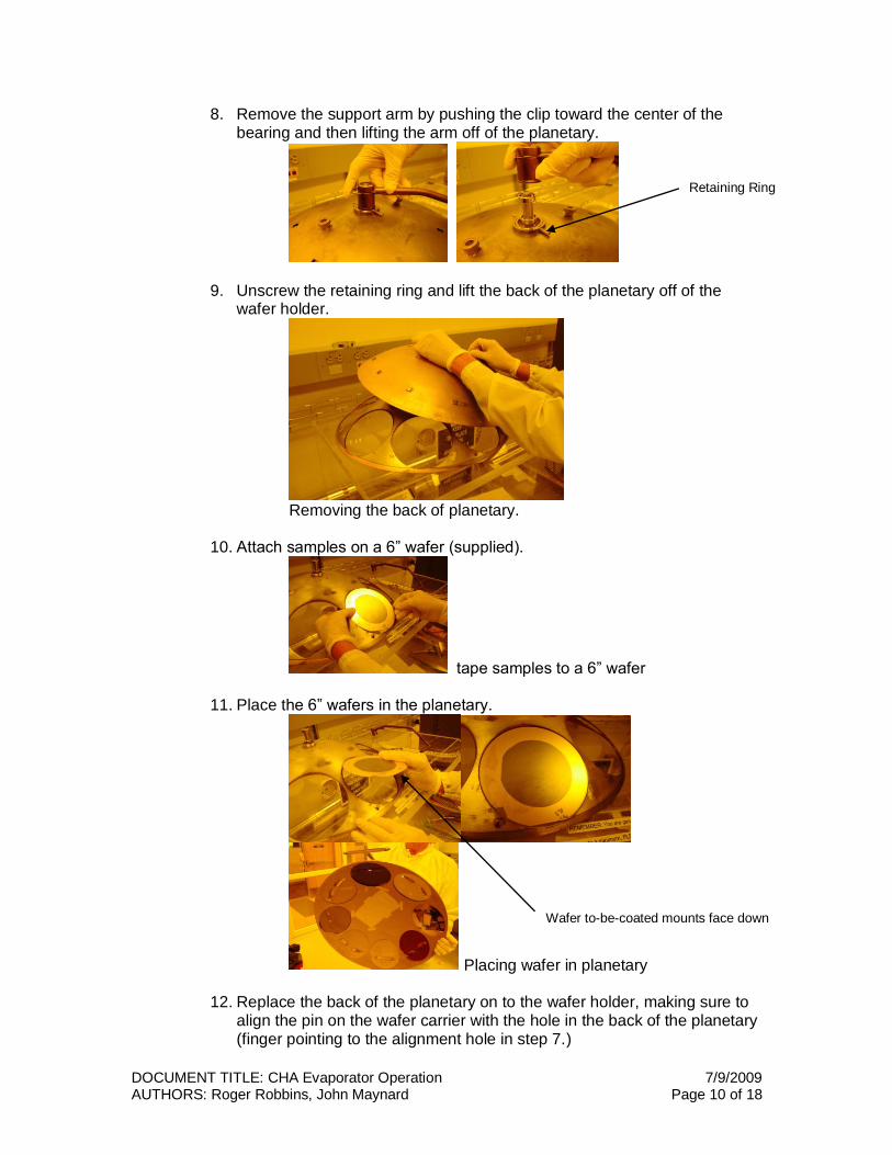
8. Remove the support arm by pushing the clip toward the center of the bearing and then lifting the arm off of the planetary.
9. Unscrew the retaining ring and lift the back of the planetary off of the wafer holder.
Removing the back of planetary.
10. Attach samples on a 6” wafer (supplied).
tape samples to a 6” wafer
11. Place the 6” wafers in the planetary.
Placing wafer in planetary
12. Replace the back of the planetary on to the wafer holder, making sure to align the pin on the wafer carrier with the hole in the back of the planetary (finger pointing to the alignment hole in step 7.)
Retaining Ring
Wafer to-be-coated mounts face down
DOCUMENT TITLE: CHA Evaporator Operation 7/9/2009 AUTHORS: Roger Robbins, John Maynard Page 11 of 18
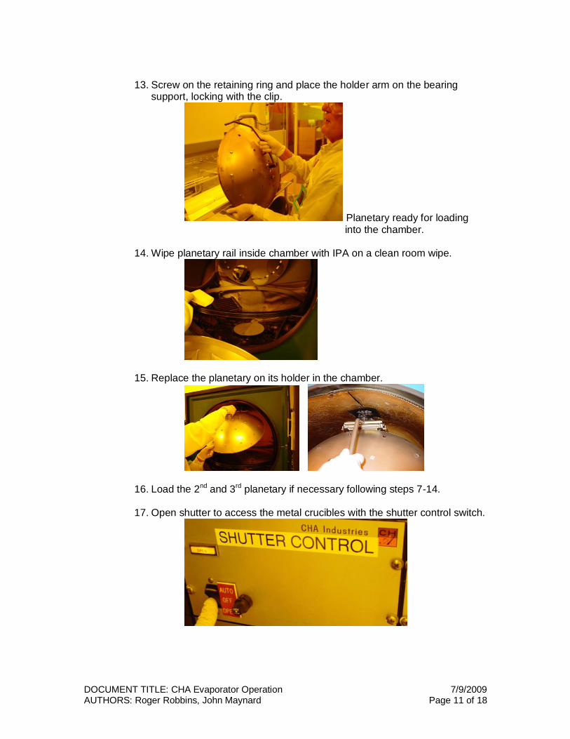
13. Screw on the retaining ring and place the holder arm on the bearing
support, locking with the clip.
Planetary ready for loading into the chamber.
14. Wipe planetary rail inside chamber with IPA on a clean room wipe.
15. Replace the planetary on its holder in the chamber.
16. Load the 2nd and 3rd planetary if necessary following steps 7-14.
17. Open shutter to access the metal crucibles with the shutter control switch.
DOCUMENT TITLE: CHA Evaporator Operation 7/9/2009 AUTHORS: Roger Robbins, John Maynard Page 12 of 18
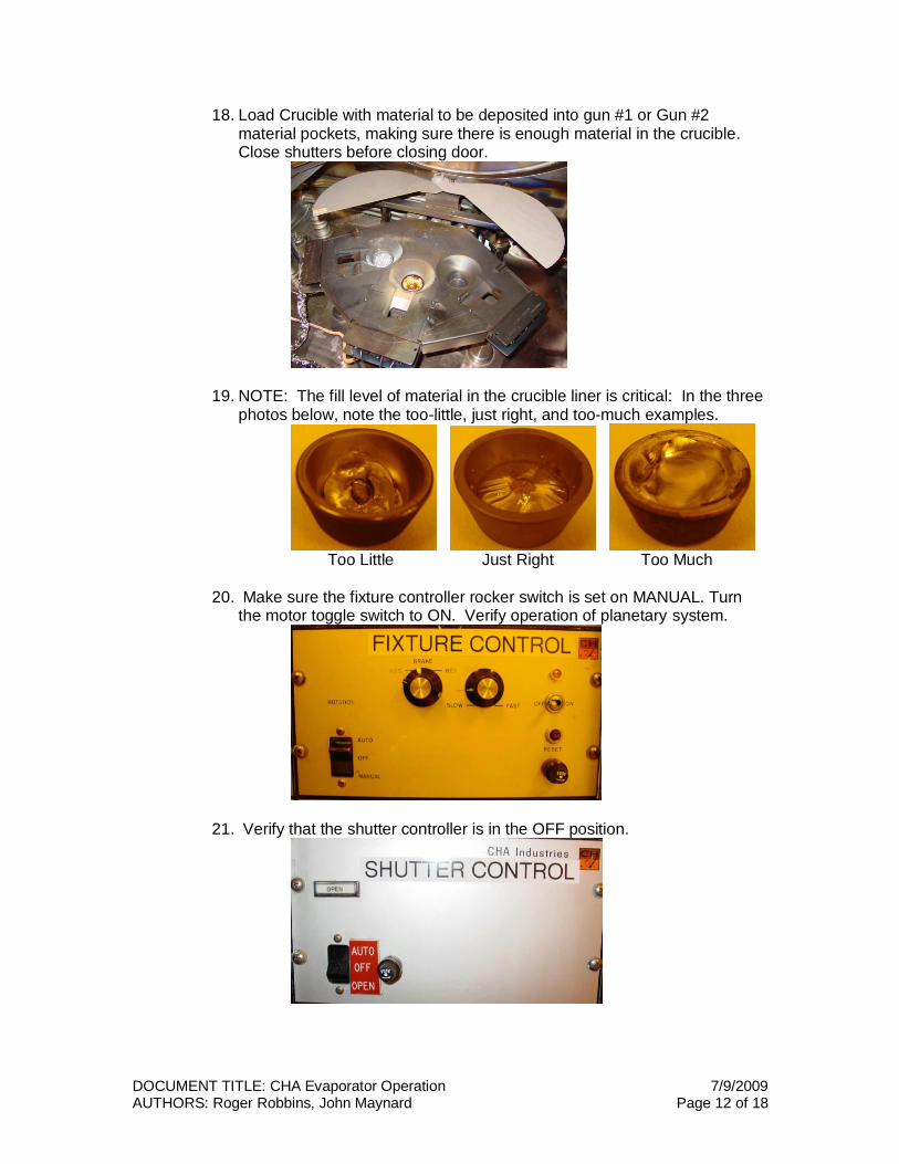
18. Load Crucible with material to be deposited into gun #1 or Gun #2 material pockets, making sure there is enough material in the crucible. Close shutters before closing door.
19. NOTE: The fill level of material in the crucible liner is critical: In the three photos below, note the too-little, just right, and too-much examples.
Too Little Just Right Too Much
20. Make sure the fixture controller rocker switch is set on MANUAL. Turn the motor toggle switch to ON. Verify operation of planetary system.
21. Verify that the shutter controller is in the OFF position.
DOCUMENT TITLE: CHA Evaporator Operation 7/9/2009 AUTHORS: Roger Robbins, John Maynard Page 13 of 18
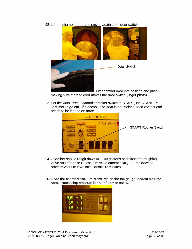
22. Lift the chamber door and push it against the door switch.
Lift chamber door into position and push, making sure that the door makes the door switch (finger photo).
23. Set the Auto Tech II controller rocker switch to START, the STANDBY light should go out. If it doesn’t, the door is not making good contact and needs to be leaned on more.
24. Chamber should rough down to ~100 microns and close the roughing valve and open the Hi-Vacuum valve automatically. Pump down to process vacuum level takes about 30 minutes.
25. Read the chamber vacuum pressures on the Ion gauge readout pictured
here. Processing pressure is 5X10⁻⁶ Torr or below.
START Rocker Switch
Door Switch
DOCUMENT TITLE: CHA Evaporator Operation 7/9/2009 AUTHORS: Roger Robbins, John Maynard Page 14 of 18
26. Wait until pressure reaches desired value before beginning the deposition process.
Evaporation Process
Setup Film thickness Monitor and Beam Control Parameters
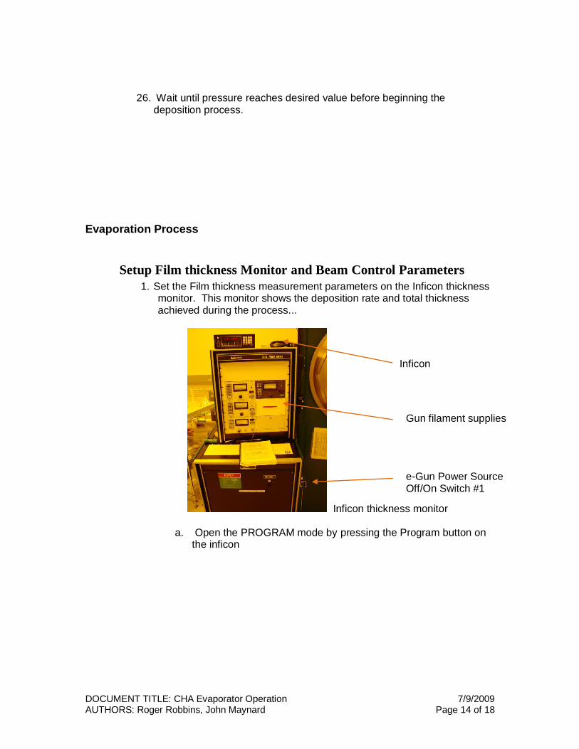
1. Set the Film thickness measurement parameters on the Inficon thickness monitor. This monitor shows the deposition rate and total thickness achieved during the process...
Inficon thickness monitor
a. Open the PROGRAM mode by pressing the Program button on the inficon
Inficon Inficon
e-Gun Power Source Off/On Switch #1
Gun filament supplies
DOCUMENT TITLE: CHA Evaporator Operation 7/9/2009 AUTHORS: Roger Robbins, John Maynard Page 15 of 18
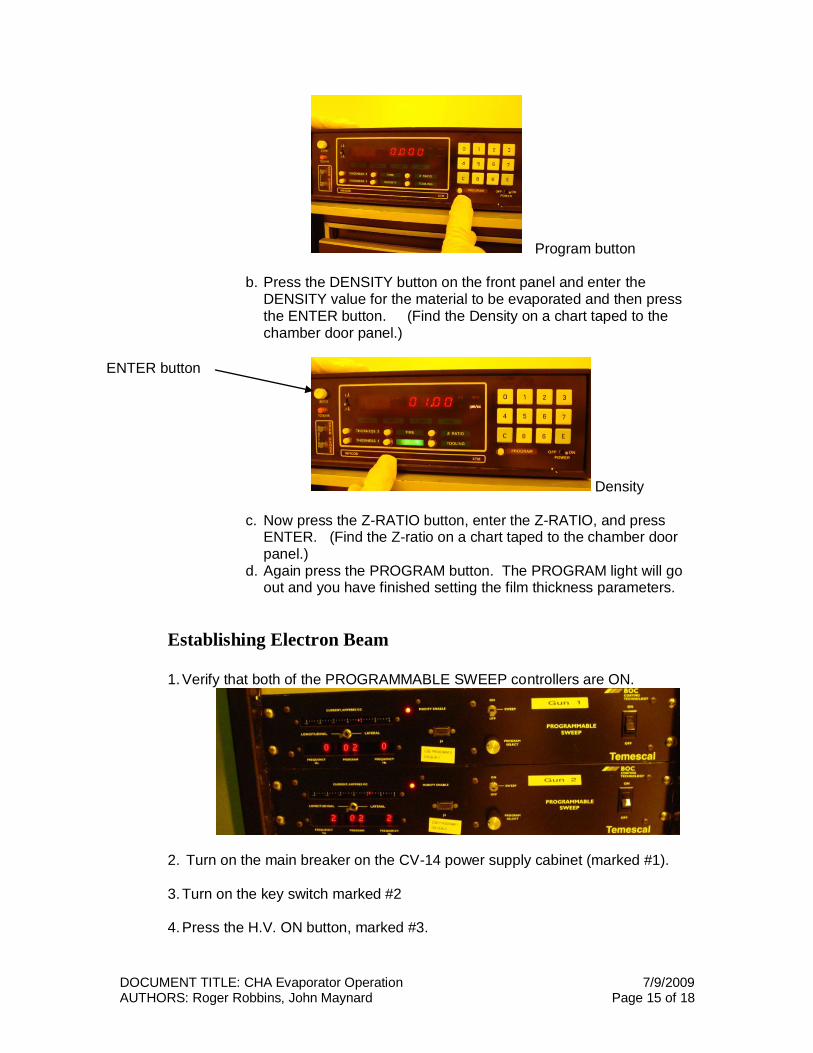
Program button
b. Press the DENSITY button on the front panel and enter the DENSITY value for the material to be evaporated and then press the ENTER button. (Find the Density on a chart taped to the chamber door panel.)
Density
c. Now press the Z-RATIO button, enter the Z-RATIO, and press ENTER. (Find the Z-ratio on a chart taped to the chamber door panel.)
d. Again press the PROGRAM button. The PROGRAM light will go out and you have finished setting the film thickness parameters.
Establishing Electron Beam
1. Verify that both of the PROGRAMMABLE SWEEP controllers are ON.
2. Turn on the main breaker on the CV-14 power supply cabinet (marked #1).
3. Turn on the key switch marked #2
4. Press the H.V. ON button, marked #3.
ENTER button
DOCUMENT TITLE: CHA Evaporator Operation 7/9/2009 AUTHORS: Roger Robbins, John Maynard Page 16 of 18
5. Make sure the filament current knob is set to zero on the E-GUN CONTROLLER for whichever gun will be used; Gun #1 or Gun #2.
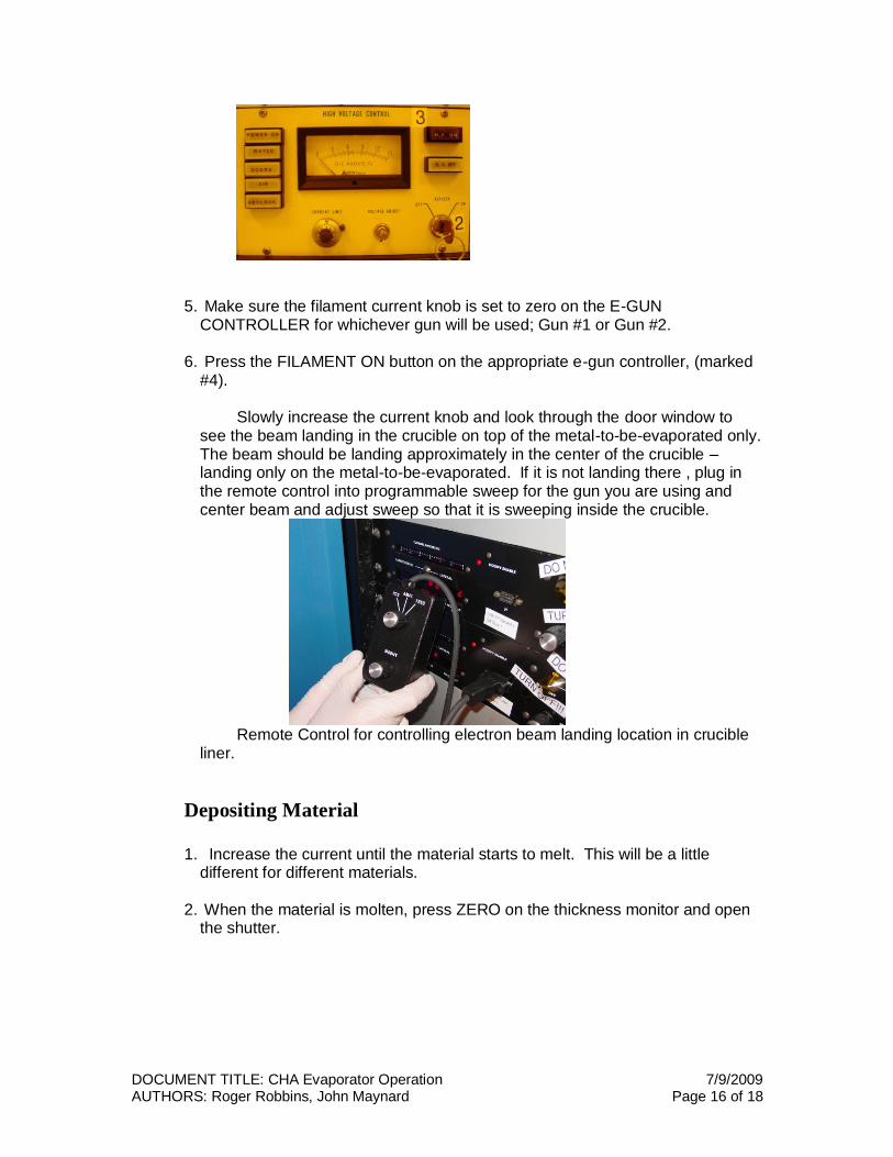
6. Press the FILAMENT ON button on the appropriate e-gun controller, (marked #4). Slowly increase the current knob and look through the door window to see the beam landing in the crucible on top of the metal-to-be-evaporated only. The beam should be landing approximately in the center of the crucible – landing only on the metal-to-be-evaporated. If it is not landing there , plug in the remote control into programmable sweep for the gun you are using and center beam and adjust sweep so that it is sweeping inside the crucible.
Remote Control for controlling electron beam landing location in crucible liner.
Depositing Material
1. Increase the current until the material starts to melt. This will be a little
different for different materials.
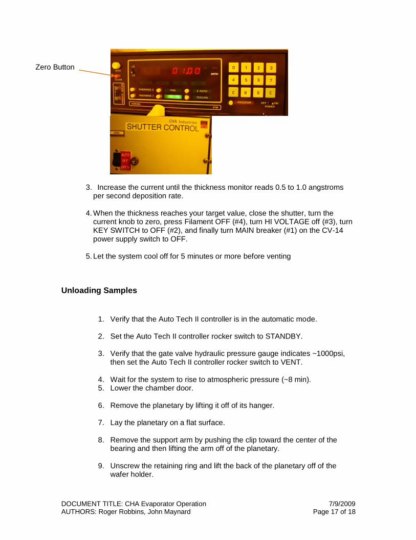
2. When the material is molten, press ZERO on the thickness monitor and open the shutter.
DOCUMENT TITLE: CHA Evaporator Operation 7/9/2009 AUTHORS: Roger Robbins, John Maynard Page 17 of 18
3. Increase the current until the thickness monitor reads 0.5 to 1.0 angstroms per second deposition rate.
4. When the thickness reaches your target value, close the shutter, turn the current knob to zero, press Filament OFF (#4), turn HI VOLTAGE off (#3), turn KEY SWITCH to OFF (#2), and finally turn MAIN breaker (#1) on the CV-14 power supply switch to OFF.
5. Let the system cool off for 5 minutes or more before venting
Unloading Samples
1. Verify that the Auto Tech II controller is in the automatic mode.
2. Set the Auto Tech II controller rocker switch to STANDBY.
3. Verify that the gate valve hydraulic pressure gauge indicates ~1000psi, then set the Auto Tech II controller rocker switch to VENT.
4. Wait for the system to rise to atmospheric pressure (~8 min). 5. Lower the chamber door.
6. Remove the planetary by lifting it off of its hanger.
7. Lay the planetary on a flat surface.
8. Remove the support arm by pushing the clip toward the center of the
bearing and then lifting the arm off of the planetary.
9. Unscrew the retaining ring and lift the back of the planetary off of the wafer holder.
Zero Button
DOCUMENT TITLE: CHA Evaporator Operation 7/9/2009 AUTHORS: Roger Robbins, John Maynard Page 18 of 18
10. Remove the 6 in wafers, un-tape your samples and take them with you.
11. Replace the back of the planetary on to the wafer holder, making sure to align the pin on the wafer carrier with the hole in the back of the planetary.
12. Screw on the retaining ring and place the holder arm on the bearing
support, locking with the clip.
13. Wipe planetary rail inside chamber with IPA on a clean room wipe.
14. Replace the planetary on its holder in the chamber.
15. Open shutter to access the metal crucibles with the shutter control switch.
16. Remove crucibles and store them in the crucible storage box making sure that they are placed under the proper label. Close shutters before closing door.
17. Make sure the fixture controller rocker switch is set on MANUAL. Turn
the motor toggle switch to ON. Verify operation of planetary drive and then turn off the toggle switch.
18. Verify that the shutter controller is in the OFF position.
19. Lift the chamber door and push it against the door switch. Lift chamber door into position and push, making sure that the door makes the door switch (finger photo).
20. Set the Auto Tech II controller rocker switch to START. The STANDBY light should go out. If it doesn’t, the door is not making good contact and needs to be leaned on more.
21. Chamber should rough down to ~100 microns and close the roughing valve and open the Hi-Vacuum valve automatically. Pump down to process vacuum level takes about 30 minutes.
22. Done! Make sure the area is clean and take your samples with you.