Embed Size (px)
Citation preview
CH.4 Full-wave and Three-
phase rectifiers
(Converting AC to DC)
4-1 Introduction
� The average current in AC source is zeroin the full-wave rectifier, thus avoiding problemsassociated with nonzero average source currents, particularly in transformers.
� The output of the full-wave rectifier has inherentlyless ripple than the half-wave rectifier.
� Uncontrolled and controlled single-phase and three-phase full-wave converters used as rectifiers areanalyzed.

4-2 Single-phase full-wave rectifiers
Fig. 4-1 Bridge rectifier::::
The lower peak diode voltage make it more suitablefor high-voltage applications.
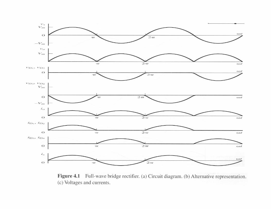

Fig. 4-2 center-tapped transformer
rectifier
With electrical isolation, only
one diode voltage drop betweenthe source and load, suitable for
low-voltage, high-current applications

Resistive load::::
π≤≤π−
π≤≤=
2
0 0
wt,wtsinVm
wt,wtsinVm)wt(v
∫ ==π
ππ 02)()sin(
1 VmwtdwtVmVo
)(2
RVm
RVoIo π==
2Im=Irms
power absorbed by the load resistor:
rmsRIPR
2=power factor :Pf=1
R-L load:::: Fig.4-3

∑∞
=π++=
‧‧420 ,,n)nwtcos(VnVo)wt(v
π= VmVo 2
+
−−
=1
1
1
12
nn
VmVn
π
RVoIo = |jnwLR|
VnZn
VnIn+
==
If L is relatively large, the load current is essentially
dc. ( )
R>> L for
IoIrms
R
Vm
R
VoIo)wt(i
ω
≈π
==≈
2
Source harmonics are rich in the odd-numbered harmonics.
Filters:reducing the harmonics.
R>> L ω
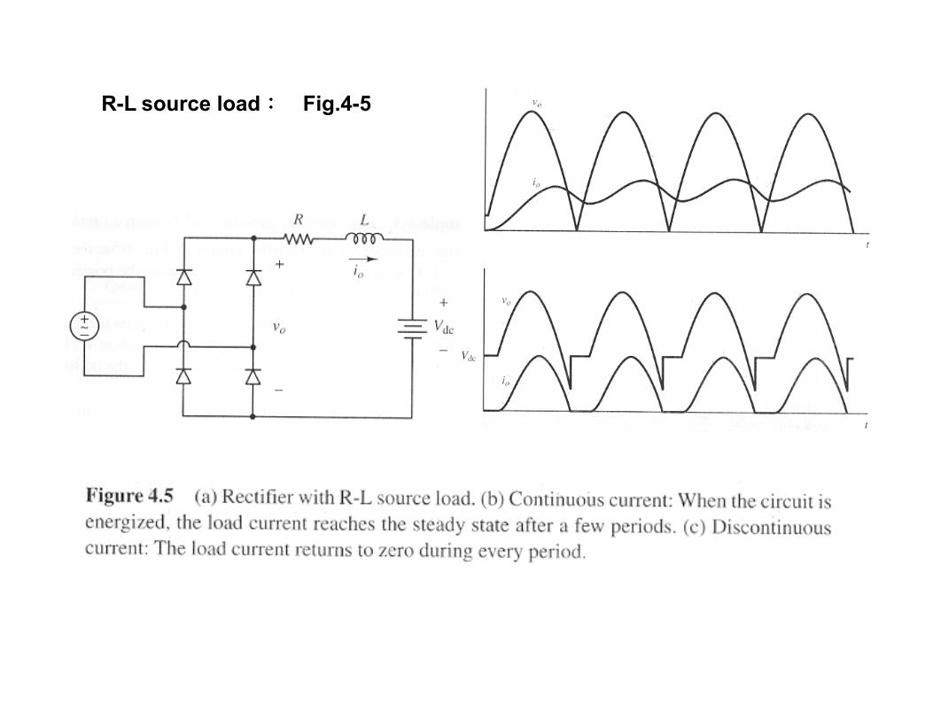
R-L source load:::: Fig.4-5

For continuous current operation, the only modification to
the analysis that was done for R-L load is in the dc
term of the Fourier series .The dc component of current
in this circuit is.
R
VdcVm
R
VdcVoIo
−=
−= π
2
The sinusoidal terms in the Fourier analysis
are unchanged by the dc source, provided
that the current is continuous.
Discontinuous current is analyzed like
section 3-5.
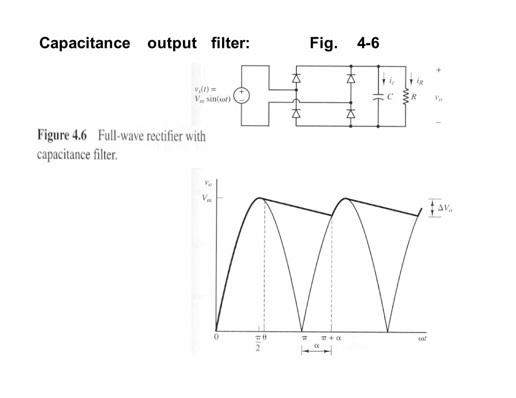
Capacitance output filter: Fig. 4-6

Assuming ideal diodes
θ=
θ−− off diodes , e sinVm
on pair diode one,|wtsinVm|)wt(v
)wRc/()wt(
0
θ:the angle where the diodes become reverse biased,
which is the same as for the half-wave rectifier
and is
π+ω−=ω−=θ −− )RC(Tan)RC(Tan 11
απ +=wt
)sin(Vme sinVm )RC/()( α+π−=θ ωθ−α+π−
0=α−θ ωθ−α+π−sine)(sin
)RC/()(
α=? �solved numerically forα
Peak-to-peak variation(ripple):
)sin1(|)sin(| ααπ −=+−=∆ VmVmVmVo

In practical circuits where ωRC
,2
, 2
παπθ ≈≈
minimal output voltage occurs at α+π=wt
)RC/()RC/()(
e Vme Vm)(v ωπ−ωπ
−π
+π−==α+π 22
0
[ ]
fRC
Vm
RC
Vm
RCVm
eVme VmVmVo )RC/()RC/(
2
11
1
‧
‧
=ω
π=
ωπ
−−=
−=−≈∆ ωπ−ωπ−
fw
xxxe x
π2
...321
132
=
++++=!!!
is half that of the half-wave rectifier.
π>>

Fig. 4-7 (a) Voltage doubler
Fig. 4-7 (b) Dual voltage rectifier
=full-wave rectifier(sw. open)+
voltage doubler(sw. closed)

L-C filtered output:::: Fig.4-8
C holds the output voltage at a constant level, and the L
smoothes the current from rectifier and reduces the peak
current in diodes.

Continuous
Current:
(LV 2 Qπ
VmVoVx == =0 , full-wave rectified )
0 , )(
2 ==== IcR
VmR
VoIIRL π
LiThe variation in can be estimate from the first
Ac term (n=2) in the Fourier series.
The amplitude of the inductor current for n=2 is
L
Vm
L
/Vm
L
V
Z
VI
πω=
ωπ
=ω
==3
2
2
34
22 2
2
2
where 21
1
1
12=
+
−−π
= n , nn
VmVn
For Continuous current, LII <2
R
Vm
L
Vm
π<
πω2
3
2
ω>
3
RL � 1
3>
ωR
L

Discontinuous current:
When is positive ( at ),
VowtVv mL −= sin
[ ]
( )[ ]
? i
,wt for
wtVowtVmL
wtdVowtVmL
wti
L
wt
L
==
<≤≤
−−−=
−= ∫
ββ
πββα
ααω
ω α
,0)(
,
)cos(cos1
)(sin1
)(
Li VowtVm
=sin α=wt
= −
Vm
Vo1sinα

Procedure for determining Vo:
(1) Estimate a Value for Vo slightly below Vm, and solve ?=α
(2) Solve numerically,β )()cos(cos0)( αββαβ −−−== VoVmiL
(3) Solve
[ ]∫
∫β
α
β
α
α−−−αωπ
=
π=
)wt(d)wt(Vo)wtcos(cosVmL
)wt(d)wt(iILL
11
1
(4) Slove Vo= RI L
(5) Repeat step (1)~(4) until the computed Vo in step(4)
equals the estimated Vo in step(1)
Output Voltage for discontinuous current is larger than
for continuous current.(see Fig4-8(d))

4-3 controlled full-wave rectifiers
Resistive load:::: Fig.4-10

)cos(Vm
)wt(d)wtsin(VmVo
α+π
=
π= ∫
π
α
1
1angle delay=α
)cos1( απ
+==R
Vm
R
VoIo
πα
πα
π
π
α
4
)2sin(
22
1
)()sin(1 2
+−=
= ∫
R
Vm
wtdwtR
VmI rms
The power delivered to the load rmsRIP 2=
The rms current in source is the same as the rms current in
the load.
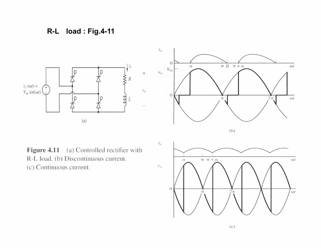
R-L load : Fig.4-11

Analysis of the controlled full-wave rectifier operating in the
discontinuous current mode is identical to that of the controlled
half-wave rectifier, except that the period for the output current
is .π
[ ])/()t(
o e)sin()tsin(Z
Vm)wt(i
ωτα−ω−θ−α−θ−ω= for β≤ω≤α t
RL , )
R
L(tan
)L(RZ
=τω
=θ
ω+=
−1
22
For discontinuous current παβ +<
discontinuous current :

continuous current
0)( , ≥++= απαπ iwt
[ ]
current continuous for
R
LTan
0 )-(
0 )- sin(
e
e
1- )(
01)sin(
0)sin()sin(
)/(
)/()(
ωθα
αθ
αθαθ
θαθαπωτπ
ωτααπ
=≤
≥
≥
≥+−
≥−−−+−
−+−
,....6,4,2
1
)1sin(
1
)1sin(2
1
)1cos(
1
)1cos(2
cos2
)(sin1
)cos()(
22
1
=
−−
−++
=
−−
−++
=
+=
==
++=
∫
∑
+
∞
=
n
n
n
n
nVmb
n
n
n
nVma
baVn
Vmwtd wtVmVo
nnwtVnVowtv
n
n
nn
n
0
ααπ
ααπ
αππ
θ
απ
α
)(an
bnTann 1- −
=θ
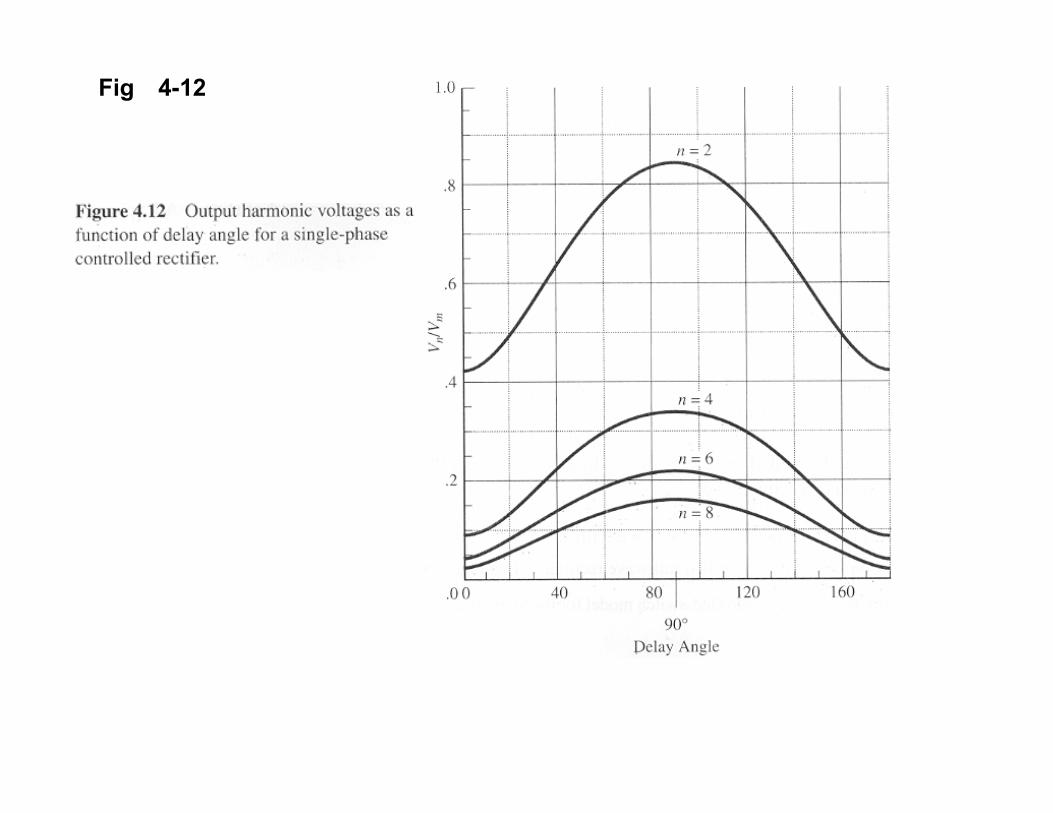
Fig 4-12
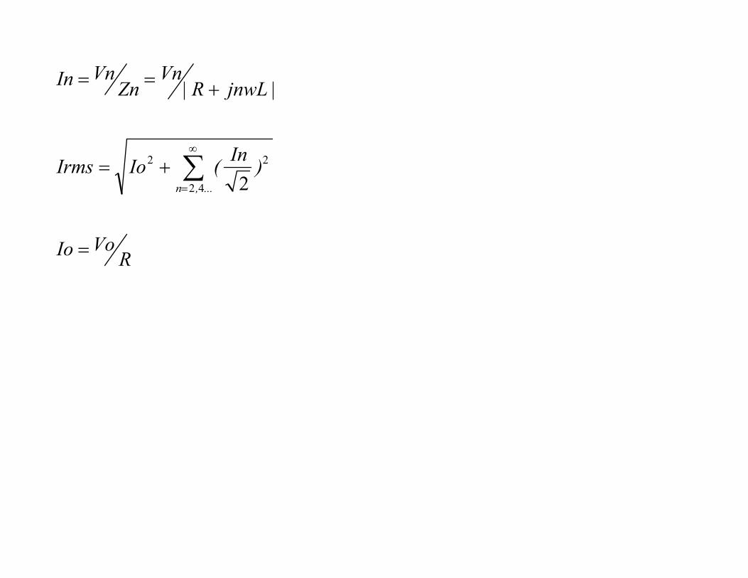
RVoIo
)In
(IoIrms
|jnwLR|Vn
ZnVnIn
...,n
=
+=
+==
∑∞
= 42
22
2

R-L Source load :::: Fig.4-14
The SCRS may be turned on at any time that they are
forward biased, which is at an angle
)(sin 1
VmVdc−≥α
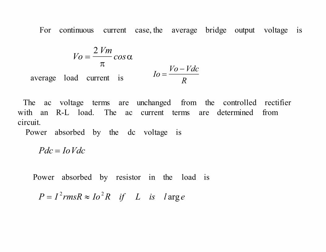
For continuous current case, the average bridge output voltage is
average load current is
The ac voltage terms are unchanged from the controlled rectifier
with an R-L load. The ac current terms are determined from
circuit.
Power absorbed by the dc voltage is
elisLifRIormsRIP arg 22 ≈=
απ
= cosVm
Vo2
R
VdcVoIo
−=
VdcIoPdc =
Power absorbed by resistor in the load is
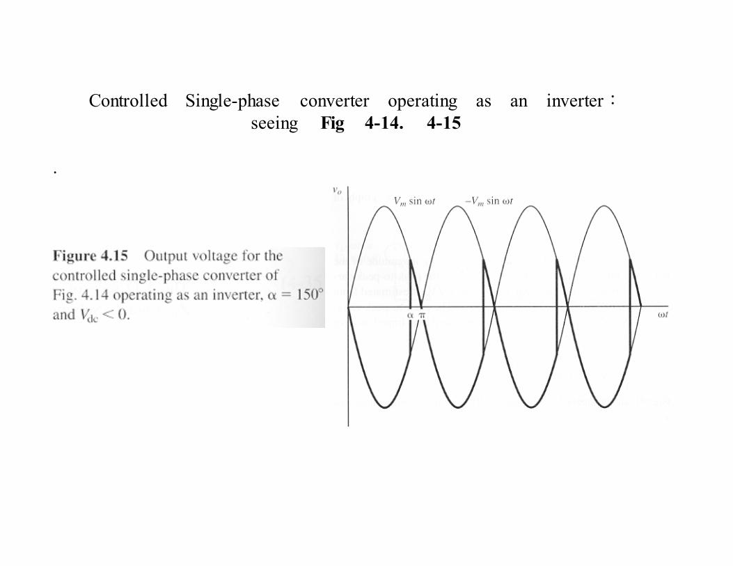
Controlled Single-phase converter operating as an inverter:seeing Fig 4-14. 4-15
.
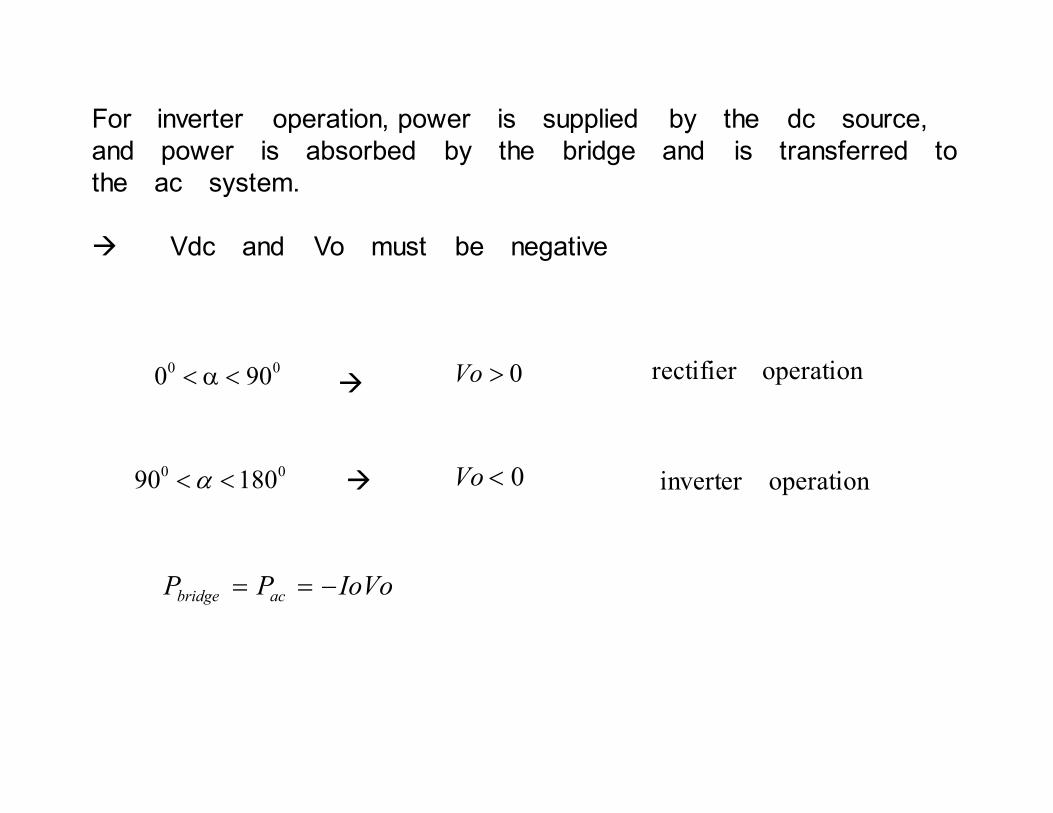
00900 <α< � 0>Vo rectifier operation
0018090 <<α � 0<Vo inverter operation
IoVoPP acbridge −==
For inverter operation, power is supplied by the dc source,
and power is absorbed by the bridge and is transferred to
the ac system.
� Vdc and Vo must be negative

4-4 Three-phase rectifiers
Resistive load : Fig 4-16


上、下半部Diode,每次僅一個ON;同相上、下Diode不可同時ON;Diode ON由瞬間最大線電壓決定。
A transition of the highest line-to-line voltage must take place
every
.
Because of the six transitions that occur for each period
of the source voltage, the circuit is called a six-pulse
rectifier.
vo(t)之基頻為3 電源頻率之6倍
Diode turn on in the sequence 1,2,3,4,5,6,1,..
00606/360 =
φ
−=
−=
−=
25
63
41
DDc
DDb
DDa
iii
iii
iii

Each diode conducts one-third of the time, resulting in
avgoavgD II ,,3
1=
rmsormsDII
,,3
1=
rmsormsS II ,,3
2=
Apparent power from the three-phase source is
rms,Srms,LL IV S −= 3

...,,,n , )n(
V V
V.
V)wt(wtdsinV
/V
)tnwcos(VVo)t(v
LL,m
n
LL,m
LL,m/
/LL,m
..,,n
n
181261
6
950
3
3
1
2
32
30
0
18126
0
=−π
=
=π
=π
=
π++=
−
−
−π
π −
∞
=
∫
∑
Since the output voltage is periodic with period 1/6 of the ac
supply voltage, the harmonics in the output are of order 6kω,
k=1,2,3,1
Adevantage:output is inherently like a dc voltage, and the high-
frequency low-amplitude harmonics enable filters to be effective.

For a dc load current (constant I0) --- Fig4.17

....twcostwcostwcostwcostw(cosI i oa 00000 1313
111
11
17
7
15
5
132+−+−
π=
which consists of terms at fundamental frequency of the ac
system and harmonics of order 6k ± 1, k=1,2,3,1
Filters(Fig.4-18) are frequently necessary to prevent harmonic
currents to enter the ac system.
Resonant filters for 5th and 7th harmonics.
High-pass filters for higher order harmonics.
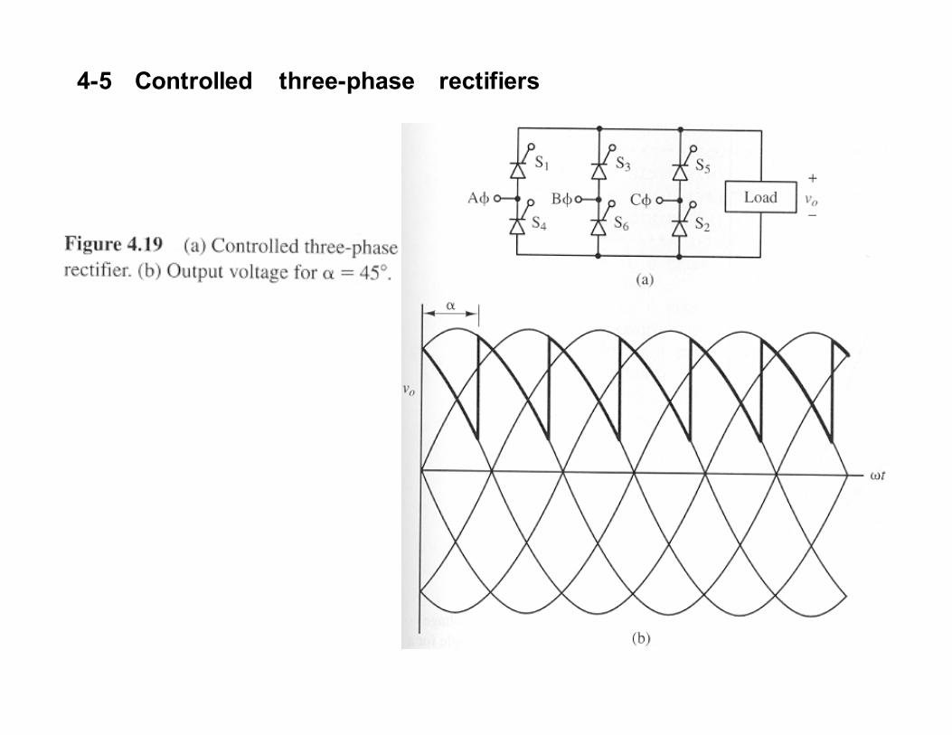
4-5 Controlled three-phase rectifiers

απ
πα
π
απ
cos)3
(
)(sin
3
1
,
3
2
3
,
LLm
LLmo
V
wtwtdVV
−
+
+−
=
= ∫
Harmonics for output voltage remain of order 6k, but amplitude are
functions of α
. � seeing Fig. 4-20


Twelve-pulse rectifiers:using two six-pulse bridges
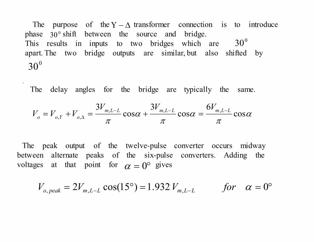
The purpose of the transformer connection is to introduce
phase shift between the source and bridge.
This results in inputs to two bridges which are
apart. The two bridge outputs are similar, but also shifted by
∆−Υ030
030
030
.
The delay angles for the bridge are typically the same.
απ
απ
απ
cos6
cos3
cos3
,,,
,,
LLmLLmLLm
oYoo
VVVVVV
−−−∆ =+=+=
The peak output of the twelve-pulse converter occurs midway
between alternate peaks of the six-pulse converters. Adding the
voltages at that point for gives°= 0α
°==°= −− 0932.1)15cos(2 ,,, α for V VV LLmLLmpeako
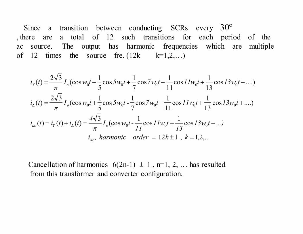
Since a transition between conducting SCRs every
, there are a total of 12 such transitions for each period of the
ac source. The output has harmonic frequencies which are multiple
of 12 times the source fre. (12k k=1,2,…)
°30
,...2,1112
cos1
cos1
(cos3
)()()(
....)cos13
1cos
11
1cos
7
1cos
5
1(cos
32)(
....)cos13
1cos
11
1cos
7
1cos
5
1(cos
32)(
000
00000
00000
=±=
−+=+=
++−+=
−+−+−=
∆
∆
k ,k order harmonic ,i
...)tw1313
tw1111
-twI4
tititi
tw13tw11tw7-tw5twIti
tw13tw11tw7tw5twIti
ac
oYac
o
oY
π
π
π
Cancellation of harmonics 6(2n-1) 1 , n=1, 2, … has resulted
from this transformer and converter configuration.
±
This principle can be expanded to arrangements of higher pulse
number by incorporating increased number of six-pulse converters
with transformers which have the appropriate phase shifts.
The characteristic ac harmonics of a p-pulse converter will be
pk 1 , k=1,2,31±
� More expense for producing high-voltage transformers with the
appropriate phase shifts.
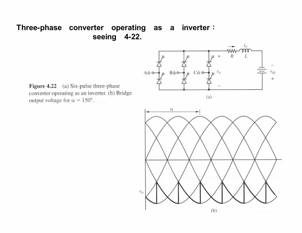
Three-phase converter operating as a inverter::::seeing 4-22.

The bridge output voltage Vo must be negative.
operation Inverter -- 0Vo ,
operation Rectifier -- 0Vo ,
><°<<°
>>°<<
18090
900
αα

4-6 DC power transmission
․ By using controlled twelve-pulse converter (generally).
․ Used for very long distances of transmission lines.
Advantages:(1) , voltage drop↓ in lines
(2) , line loss
0=LX
∞=C
X ( ↓currentline Q
(3) Two conductors required rather than three
(4) Transmission towers are smaller.
(5 ) Power flow in a dc transmission line is controllable
by adjustment of delay angles at the terminals.
(6) Power flow can be modulated during disturbances on
one of the ac system. � System stability increased.
(7) The two ac systems that are connected by the dc
line do not need to be in synchronization.
)
Disadvantages:costly ac-dc converter, filter, and control system
required at each end of the line to interface
with the ac system.

Fig.4-23 using six-pulse converter

°<<°−
°<<+=
inverter
rectifierVV oo
18090 ,
900 , , 21 α
α
For current being ripple free
2
,2
2
1
,1
1
21
cos3
cos3
απ
απ
LLm
o
LLm
o
oo
o
VV
VV
R
VVI
−
−
=
=
+=
Power supplied by the converter at terminal 1 isoo IVP 11 =
Power supplied by the converter at terminal 2 is oo IVP 22 =

Fig.4-24 using twelve-pulse converter
(a bipolar scheme)

One of the lines is energized at and the other is energized
at - . In emergency situations, one pole of the line can operate
without the other pole, with current returning through the ground path.
dcV+dcV

4-7 commutation ::::effect of source inductance ( )
Single-phase bridge rectifier: Fig.4-25sX
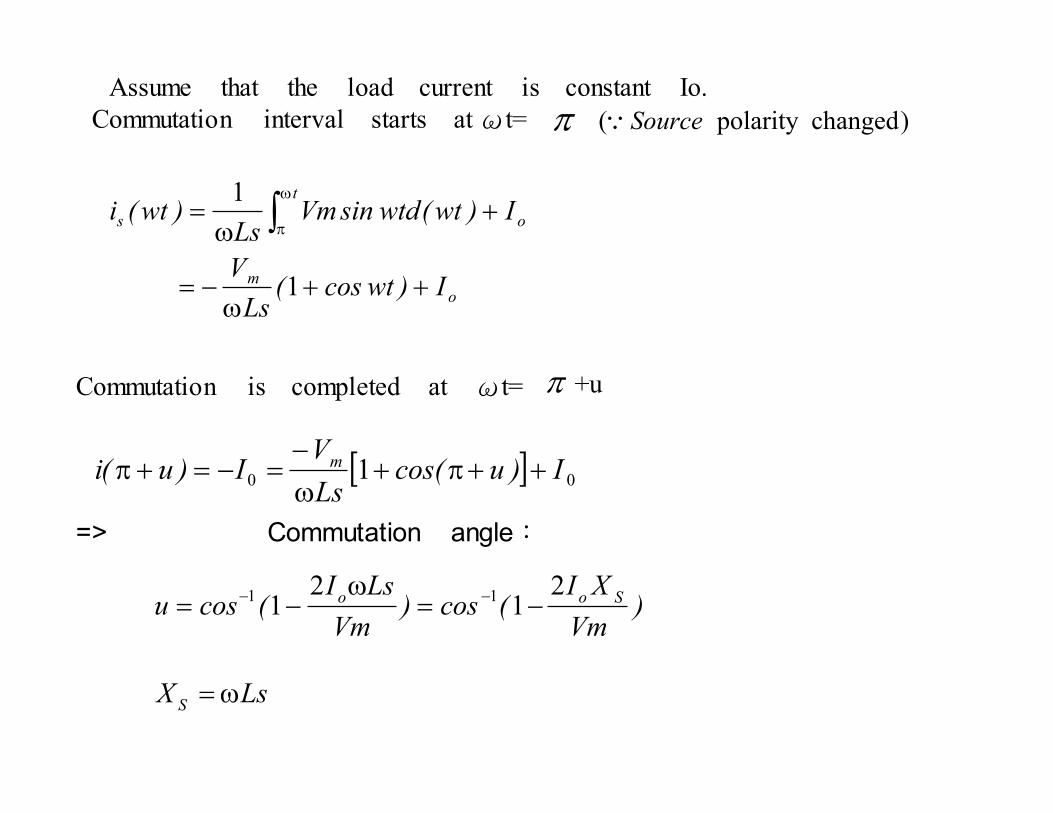
Assume that the load current is constant Io.
Commutation interval starts at ωt= π )changedpolarity ( SourceQ
o
m
t
os
I)wtcos(Ls
V
I)wt(wtdsinVmLs
)wt(i
++ω
−=
+ω
= ∫ω
π
1
1
Commutation is completed at ωt= π +u
[ ] 00 1 I)ucos(Ls
VI)u(i m ++π+
ω
−=−=+π
)Vm
XI(cos)
Vm
LsI(cosu Soo
21
21
11 −=ω
−= −−
=> Commutation angle:
LsXS
ω=

Average load voltage is
)V
XI(
2V
)ucos(V
)wt(d wtsinVV
m
som
m
muo
−π
=
+π
=π
= ∫π
1
11
Source inductance lowers the average output voltage of full-
wave rectifier.

Three-phase rectifier:::: Fig.4-26
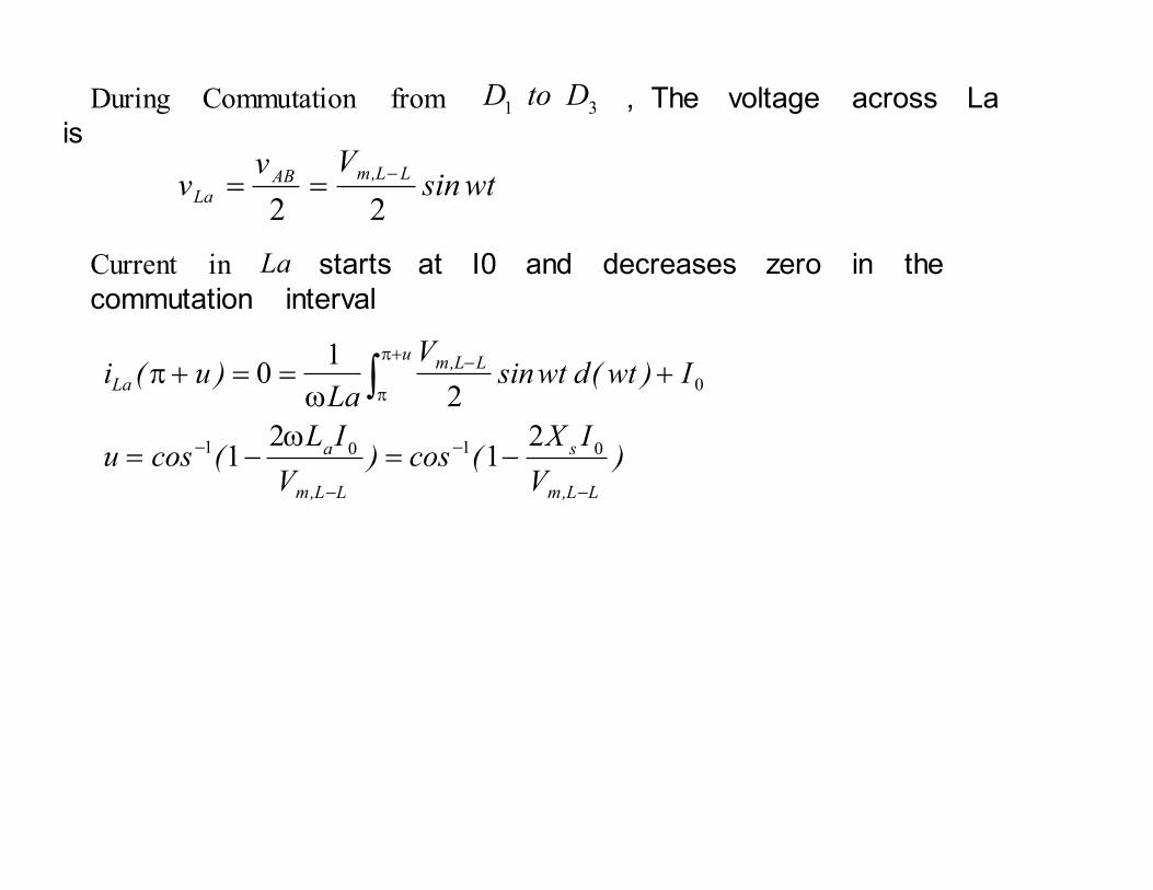
During Commutation from , The voltage across La
is31
DtoD
wtsinVv
vLL,mAB
La22
−==
Current in starts at I0 and decreases zero in the
commutation interval
La
)V
IX(cos)
V
IL(cosu
I)wt(d wtsinV
La)u(i
LL,m
s
LL,m
a
uLL,m
La
−
−
−
−
+π
π
−
−=ω
−=
+ω
==+π ∫0101
0
21
21
2
10

During the commutation interval from , the converter
output voltage is31 D to D
2
ACBC
o
vvv
+=
22
2
0
BCACBCACAC
ABAC
.
.cLaLACo
BCACABCABCAB
vvvvv
vvvvvv
v-vv , vvv
+=
−−=
−=+−=
==++
Average output Voltage: 類似 Single-phase rectifier
)V
IX(
VV
LL,m
sLL,m
o
−
− −π
= 013
Source inductance lowers the average output voltage of three-
phase rectifiers.