Embed Size (px)
Citation preview

1
Chapter 22 Cutting –Tool Materials and Cutting Fluids
2222..11 IInnttrroodduuccttiioonn
The selection of cutting-tool materials for a particular application is among the most important factors in machining operations.
The complex nature of this subject forces us to rely on guidelines and recommendations that have been accumulated in industry over many years.
As noted in chapter 21, the cutting tool is subjected to: a) High temperatures, b) High contact stresses, and c) Rubbing along the tool-chip interface and along the machined surface.
Cutting Tool Characteristics: the cutting-tool material must possess the following characteristics: • Hot hardness:
So that hardness, strength, and wear resistance of the tool are maintained at the temperatures encountered in machining operations. Thus, the tool retains its shape and sharpness.
Fig. 22.1 shows tool-material hardness as a function of temperature.
Ceramics maintain their hardness at high temperatures. While carbon tool steels rapidly begin to lose their hardness at moderate temperatures (cannot be used at high speeds high temperatures).
Figure 22.1 The hardness of various cutting-tool materials as a function of temperature (hot hardness). The wide range in each group of materials is due to the variety of tool compositions and treatments available for that group. • Toughness and impact strength (mechanical
shock): so that impact forces on the tool encountered repeatedly in interrupted cutting operations (such milling) do not chip or fracture the tool.
• Thermal shock resistance: to withstand the rapid temperature cycling encountered in interrupted cutting.
• Wear resistance: so that an acceptable tool life is obtained before the tool has to be replaced. • Chemical stability and inertness with respect to the material being machined, to avoid or
minimize any adverse reactions, adhesion, and tool-chip diffusion that would contribute to tool wear.
Over the years, various cutting-tool materials with a wide range of mechanical, physical, and chemical properties have been developed (see Table 22.1).

2

3
Properties listed in first column are useful in determining desirable tool-material characteristics for a particular application. Thus, for example:
Hardness and strength are important when the workpiece has high hardness and strength. Impact strength is important when making interrupted cuts such as milling. Melting temperature of tool material is important versus the temperatures developed in the
cutting zone. Thermal conductivity and coefficient of thermal expansion are important in determining
the resistance of the tool materials to thermal fatigue and shock.
Some contradiction between desirable tool properties and the properties of the cutting tool itself; as shown in Table 22.1 (note the cost). For example:
a) High-speed steels (HSS) are tough, but they have limited hot hardness, b) Ceramics have high resistance to temperature and wear, but they are brittle and can chip.
Table 22.3 shows the operating characteristics of cutting tool materials in machining.

4
Tool materials categories are (ordered as developed and implemented in industry): 1. Carbon- and alloy-steels. 2. High-speed steels. 3. Cast-cobalt alloys. 4. Carbides. 5. Coated tools. 6. Alumina-based ceramics. 7. Cubic boron nitride. 8. Silicon-nitride-base ceramics. 9. Diamond. 10. Whisker-reinforced materials.
Carbon steels are the oldest tool materials and have been used since 1880. The hardness of carbon
steels rapidly decreases as the temperature increases (Fig. 22.1). Low-alloy and medium-alloy steels were developed later but with longer tool life. Although inexpensive and easily shaped and sharpened, these steels do not have sufficient hot
hardness and wear resistance for cutting at high speeds when temperature rises significantly. They are not of any particular significance in modern manufacturing.

5
2222..22 HHiigghh--SSppeeeedd SStteeeellss ((HHSSSS)):: Developed to machine at higher speeds than was previously possible. First produced in early
1900s. HSS are the most highly alloyed of the tool steels. They can be hardened to various depths, have good wear resistance, and are relatively
inexpensive. Because of their toughness and high resistance to fracture, HSS are especially suitable for (a)
high positive rake-angle tools, (b) interrupted cuts, (c) machine tools with low stiffness that are subjected to vibration and chatter, and (d) complex and single-piece tools.
Their most important limitation (because low hot hardness) is that cutting speeds are low compared to those of carbide tools.
Two basic types of HSS: molybdenum (M-series) and tungsten (T-series). The M-series: up to about 10% molybdenum, with chromium, vanadium, tungsten, and
cobalt as alloying elements. The T-series: 12% to 18% tungsten, with chromium, vanadium, and cobalt as alloying
elements.
The M-series generally has higher abrasion (rubbing) resistance than the T-series, undergoes less distortion during heat treating, and is less expensive. About 95% of all HSS tools are made of the M-series.
HSS tools are available in wrought (rolled or forged), cast, and P/M (sintered) forms. They can be coated for improved performance.
HSS tools may also be subjected to surface treatments (CH), for improved hardness and wear resistance or steam treatment at elevated temperatures to develop a black oxide layer for improved performance-for instance, to reduce BUE formation.
2222..33 CCaasstt CCoobbaalltt AAllllooyyss
Introduced in 1915. These alloys have the following composition 38% - 53% cobalt, 30% -33% chromium, and 10% - 20% tungsten.
Because of their high hardness (58-64 HRC), they have good wear resistance and can maintain their hardness at elevated temperatures.
They are not as tough as HSS and are sensitive to impact forces. Consequently, they are less suitable than high-speed steels for interrupted cutting operations.
Commonly known as Stellite tools, these alloys are cast and ground into relatively simple tool shapes.
Used only for special applications that involve deep, continuous roughing cuts at relatively high feeds and speeds -- as much as twice the rates possible with HSS.
2222..44 CCaarrbbiiddeess ((cceemmeenntteedd oorr ssiinntteerreedd ccaarrbbiiddeess))
The two groups of tool materials described above cannot be used as effectively where high cutting speeds (High temp.) are involved.
Introduced in the 1930’s and have high hardness over a wide range of temperatures, so can be used for higher cutting speeds.
High elastic modulus and thermal conductivity, and low thermal expansion. The most important, versatile, and cost-effective tool and die materials for a wide range of
applications. Two major groups of carbides used for machining operations are tungsten carbides and titanium
carbide.

6
2222..44..11 TTuunnggsstteenn CCaarrbbiiddeess ((WWCC)) A composite material consisting of WC particles bonded together in a cobalt matrix. These tools are manufactured with P/M techniques (sintered or cemented carbides). WC particles are first combined with cobalt in a mixer, resulting in a cobalt matrix surrounding
the WC particles. These particles, which are 1-5 μm in size, are then pressed and sintered into the desired insert shapes. Typically, amount of cobalt is 6 - 16%
As the cobalt content increases, the strength, hardness, and wear resistance of WC decrease, while its toughness increases because of the higher toughness of cobalt.
Tungsten-carbide tools are generally used for cutting steels, cast irons, and abrasive nonferrous materials, and have largely replaced HSS tools because of their better performance.
2222..44..22 TTiittaanniiuumm CCaarrbbiiddee ((TTiiCC))
Composed of TiC with a nickel-molybdenum matrix. Has higher wear resistance than WC but is not as tough. TiC is suitable for machining hard materials (mainly steels and cast irons) and for cutting at
speeds higher than those appropriate for WC. 2222..44..33 IInnsseerrttss
Inserts are individual cutting tools with several cutting points (Fig. 22.2). A square insert has eight cutting points, and triangular insert has six.
Inserts are usually clamped on the toolholder with various locking mechanisms (Fig. 22.3).
Figure 22.2 Typical carbide inserts with various shapes and chip-breaker features: Round inserts are also available, as can be seen in Figs. 22.3c and 22.4. The holes in the inserts are standardized for interchangeability in toolholders.

7
Figure 22.3 Methods of mounting inserts on toolholders: (a) clamping and (b) wing lockpins. (c) Examples of inserts mounted with threadless lockpins, which are secured with side screws.
Clamping is the preferred method of securing the insert because each insert has a number of cutting points, and after one edge is worn, it is indexed (rotated in its holder) to make available another cutting point.
Carbides inserts are available in a variety of shapes (square, triangle, round, and diamond). The strength of cutting edge of an insert depends on its shape. The smaller the included angle
(Fig. 22.4), the lower the strength of the edge.
Figure 22.4 Relative edge strength and tendency for chipping of inserts with various shapes. Strength refers to the cutting edge indicated by the included angles.
To further improve edge strength and prevent chipping, all insert edges are usually honed, chamfered, or produced with a negative land (Fig. 22.5). Most inserts are honed to a radius about 0.025 mm.
Figure 22.5 Edge preparation for inserts to improve edge strength.

8
Chip breaker features on inserts are used for (a) controlling chip flow during machining, (b) eliminating long chips, and (c) reducing vibration and heat generated (see Fig. 22.2).
Stiffness of the machine tool is of major importance when using carbide tools. Light feeds, low speeds, and chatter are detrimental because they tend to damage the tool's cutting
edge. Light feeds, for example, concentrate the forces and temperature closer to the edges of the tool,
increasing the tendency for the edges to chip off. Low cutting speeds tend to encourage cold welding of the chip to the tool. Cutting fluids should be applied continuously and in large quantities if used to minimize the
heating and cooling of the tool in interrupted cutting operations. 2222..44..44 CCllaassssiiffiiccaattiioonn ooff CCaarrbbiiddeess
With increasing global manufacturing and wider use of ISO (International Organization for Standardization) standards, carbide grades are classified using the letters P, M, and K for a range of applications including the traditional grade C used in the U.S. (see Tables 22.4 and 22.5).
Because of the wide variety of carbide compositions and the broad range of machining applications and workpiece materials involved, the efforts for ISO classification continue to be difficult.
This is true especially when comparing ISO grades with the traditional grades classified by the American National Standards Institute (ANSI), ranging from grades C1 to C8.

9
2222..55 CCooaatteedd TToooollss New alloys and engineered materials are being developed continuously since 1960. These
materials have high strength and toughness but generally are abrasive and chemically reactive with tool materials.
This led to important developments in coated tools. Coatings have unique properties such as: Lower friction, Higher adhesion, Higher resistance to wear and cracking, Acting as a diffusion barrier, and Higher hot hardness and impact resistance.
Because of such unique properties, coated tools can be used at high cutting speeds, reducing both the time required for machining operations and production costs.
Coated tools can have tool lives 10 times longer than those of uncoated tools. Figure 22.6, machining time has been reduced steadily by a factor of more than 100 since 1900.
Figure 22.6 Relative time required to machine with various cutting-tool materials, indicating the year the tool materials were first introduced. Note that machining time has been reduced by two orders of magnitude with a hundred years.

10
As a result, coated tools are now used in 40 to 80% of all machining operations, particularly in turning, milling, and drilling.
2222..55..11 CCooaattiinngg MMaatteerriiaallss aanndd CCooaattiinngg MMeetthhooddss
Commonly used coating materials are titanium nitride (TiN), titanium carbide (TiC), titanium carbonitride (TiCN), and aluminum oxide (Al2O3).
These coatings, generally in the thickness range of 2 - 15 μm, are applied on cutting tools and inserts by the following two techniques (section 34.6):
1. Chemical-vapor deposition (CVD), including plasma-assisted CVD. 2. Physical-vapor deposition (PVD).
Coatings for cutting tools, as well as for dies, should have the following general characteristics: 1. High hardness at elevated temperatures, to resist wear. 2. Chemical stability and inertness to the workpiece material, to reduce wear. 3. Low thermal conductivity to prevent temperature rise in the substrate. 4. Compatibility and good bonding to the substrate to prevent flaking. 5. Little or no porosity in the coating to maintain its integrity and strength.
Honing of the cutting edges is an important procedure for the maintenance of coating strength; otherwise, the coating may peel or chip off at sharp edges.
AA.. TTiittaanniiuumm--NNiittrriiddee CCooaattiinnggss ((TTiiNN))
It has low friction coefficient, high hardness, resistance to high temperature, and good adhesion to the substrate (which may be carbide or HSS).
Gold in color and perform well at higher cutting speeds and feeds. Flank wear is significantly lower than that of uncoated tools. See Fig. 22.7.
Figure 22.7 Schematic illustration of typical wear patterns of high-speed-steel uncoated and titanium-nitride coated tools. Note that flank wear is significantly lower for the coated tool.
Coated tools do not perform well at low cutting speeds because the coatings can be worn off by chip adhesion. Therefore, the use of appropriate cutting fluids to discourage adhesion.
BB.. TTiittaanniiuumm--CCaarrbbiiddee CCooaattiinnggss ((TTiiCC)) TiC coatings on tungsten-carbide inserts have high flank-wear resistance in machining
abrasive materials.
CC.. CCeerraammiiccss CCooaattiinnggss:: tthheeyy hhaavvee Chemical inertness. Low thermal conductivity. Resistance to high temperature. Resistance to flank and crater wear. Most commonly used ceramic coating is aluminum oxide (Al2O3). However, oxide coating
generally bond weakly to the substrate.
11
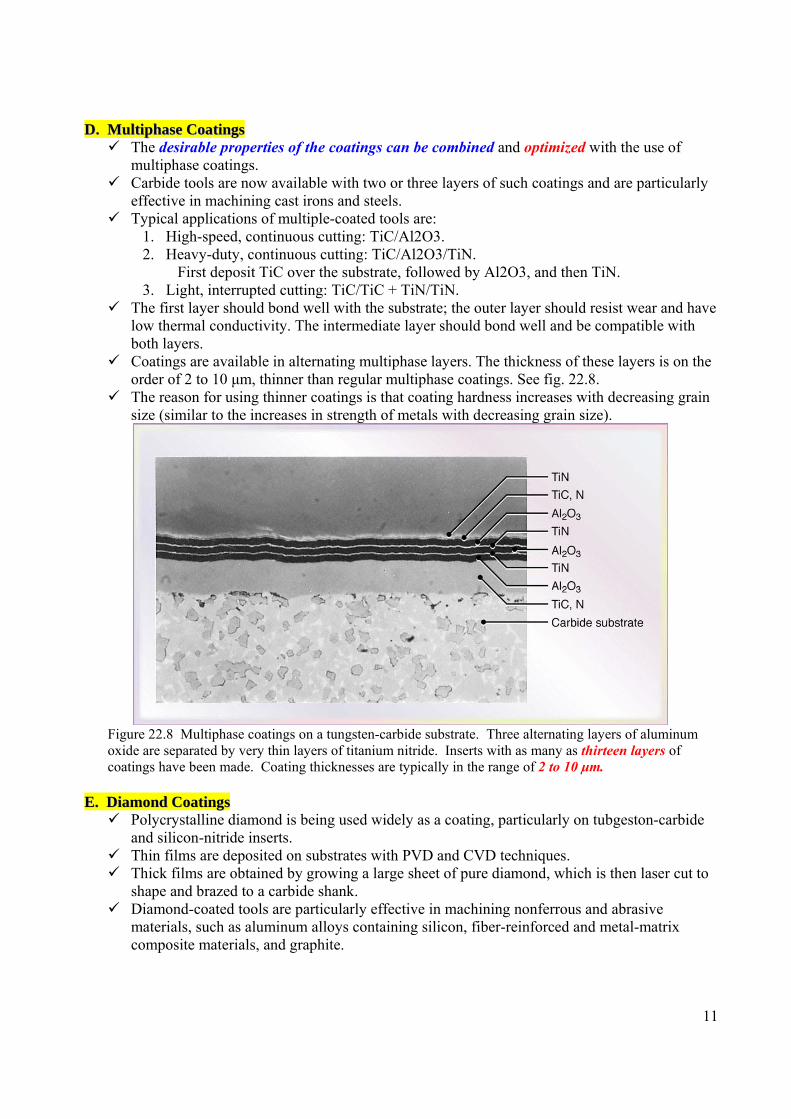
DD.. MMuullttiipphhaassee CCooaattiinnggss The desirable properties of the coatings can be combined and optimized with the use of
multiphase coatings. Carbide tools are now available with two or three layers of such coatings and are particularly
effective in machining cast irons and steels. Typical applications of multiple-coated tools are:
1. High-speed, continuous cutting: TiC/Al2O3. 2. Heavy-duty, continuous cutting: TiC/Al2O3/TiN. First deposit TiC over the substrate, followed by Al2O3, and then TiN. 3. Light, interrupted cutting: TiC/TiC + TiN/TiN.
The first layer should bond well with the substrate; the outer layer should resist wear and have low thermal conductivity. The intermediate layer should bond well and be compatible with both layers.
Coatings are available in alternating multiphase layers. The thickness of these layers is on the order of 2 to 10 μm, thinner than regular multiphase coatings. See fig. 22.8.
The reason for using thinner coatings is that coating hardness increases with decreasing grain size (similar to the increases in strength of metals with decreasing grain size).
Figure 22.8 Multiphase coatings on a tungsten-carbide substrate. Three alternating layers of aluminum oxide are separated by very thin layers of titanium nitride. Inserts with as many as thirteen layers of coatings have been made. Coating thicknesses are typically in the range of 2 to 10 μm.
EE.. DDiiaammoonndd CCooaattiinnggss
Polycrystalline diamond is being used widely as a coating, particularly on tubgeston-carbide and silicon-nitride inserts.
Thin films are deposited on substrates with PVD and CVD techniques. Thick films are obtained by growing a large sheet of pure diamond, which is then laser cut to
shape and brazed to a carbide shank. Diamond-coated tools are particularly effective in machining nonferrous and abrasive
materials, such as aluminum alloys containing silicon, fiber-reinforced and metal-matrix composite materials, and graphite.

12
2222..66 AAlluummiinnaa--BBaasseedd CCeerraammiiccss Introduced in 1950, ceramic tool materials consist primarily of fine-grained, high-purity
aluminum oxide. ( see page 222). They are cold-pressed into insert shapes under high pressure and sintered at high temperature; the
end product is referred to as white (or cold-pressed) ceramics. Additions of titanium carbide and zirconium oxide help improve properties such as toughness and
thermal-shock resistance. Alumina-based ceramic tools have very high abrasion resistance and hot hardness. See Fig. 22.9.
Figure 22.9 Ranges of mechanical properties for various groups of tool materials. See also Tables 22.1 through 22.5.
Chemically, they are more stable than HSS and carbides, so they have less tendency to adhere to metals during cutting and a correspondingly lower tendency to form a BUE.
Consequently, in cutting cast irons and steels, good surface finish is obtained with ceramic tools. However, ceramics lack toughness, and their use may result in premature tool failure by chipping
or catastrophic failure. Ceramics are effective in high-speed, uninterrupted cutting operations. Negative rake angles are generally preferred in order to avoid chipping due to the poor tensile
strength of ceramics. 2222..66..11 CCeerrmmeettss
Cermets (ceramic and metal) were first used in the early 1950s and consist of ceramic particles in a metallic matrix.
A typical cermet consists of 70% aluminum oxide and 30% titanium carbide; other cermets contain molybdenum carbide, niobium carbide, and tantalum carbide.
Although they have chemical stability and resistance to build-up edge formation, the brittleness and high cost of cermets have been a limitation to their wider use.
2222..77 CCuubbiicc BBoorroonn NNiittrriiddee ((ccBBNN))::
Next to diamond, Cubic Boron Nitride (cBN) is the hardest material presently available; introduced in 1962.
Made by bonding a 0.5-1-mm layer of polycrystalline cBN to a carbide substrate by sintering under high pressure and high temperature.

13
While the carbide provides shock resistance, the cBN layer provides very high wear resistance and cutting-edge strength (see Figs. 22.10 and 22.11). Figure 22.10 An insert of polycrystalline cubic boron nitride or a diamond layer on tungsten carbide.
Figure 22.11 Inserts with polycrystalline cubic boron nitride tips (top row), and solid-polycrystalline cBN inserts (bottom row).
cBN tools are also made in small sizes without a substrate. At elevated temperatures, cBN is chemically inert to iron and nickel, and its resistance to
oxidation is high, it is therefore particularly suitable for cutting hardened ferrous and high temperature alloys.
Because cBN tools are brittle, stiffness of the machine tool and fixturing is important in order to avoid vibration and chatter.
To avoid cracking due to thermal shock, machining should generally be performed dry, particularly in interrupted cutting operations such as milling.
2222..88 SSiilliiccoonn--NNiittrriiddee--BBaasseedd CCeerraammiiccss
Developed in 1970s, SiN based ceramics consist of silicon nitride with various additions of aluminum oxide, yttrium oxide, and titanium carbide.
These tools have toughness, hot hardness, and good thermal-shock resistance. An example of a SiN-base material is sialon, composed of: silicon, aluminum, oxygen, and
nitrogen. It has higher thermal-shock resistance than silicon nitride and recommended for machining cast
irons and nickel-based super-alloys at intermediate cutting speeds. Because of chemical affinity to iron, SiN-based tools are not suitable for machining steels.
2222..99 DDiiaammoonndd
Of all known materials, the hardest substance is diamond. As a cutting tool, it has low friction. High wear resistance. Ability to maintain sharp cutting edge. Used when good surface finish and dimensional accuracy are required particularly with soft
non-ferrous alloys, and abrasive non-metallic and metallic materials.

14
Synthetic or industrial diamonds now are used widely because natural diamond has flaws and its performance can be unpredictable.
Single-crystal diamond are used for special applications. However, they have been replaced largely by polycrystalline diamond (PCD) tools, called compacts, which also are used as dies for fine wire drawing.
These diamond tools consist of very small synthetic crystals fused by a high-pressre, high-temperature process to a thickness of about 0.1 to 1 mm and bonded to a carbide substrate, similar to CBN tools.
Because diamond is brittle, tool shape and sharpness are important. Low rack angles are generally used to provide strong cutting edge (larger included angles).
Diamond tools can be used at almost any speed, Most suitable for light uninterrupted finishing cuts. Diamond is not recommended for machining plain-carbon steels or titanium and cobalt-based
alloys, because of its strong chemical Affinity at elevated temperatures. 2222..1100 WWhhiisskkeerr--RReeiinnffoorrcceedd TTooooll MMaatteerriiaallss..
Continued progress is being made in developing new tool materials with enhanced properties such as:
High fracture toughness. Resistance to thermal shock. Cutting-edge strength. Creep resistance. Hot hardness.
Advances include the use of whiskers as reinforcing fibers in composite cutting tools. Examples of such tools are:
(a) silicon-nitride-based tools reinforced with silicon-carbide whiskers, and (b) aluminum-oxide-based tools reinforced with 25% to 40% silicon-carbide whiskers.
Silicon-carbide whiskers are typically 5 to 100 μm long and 0.1 to 1 μm diameter, Silicon carbide has high reactivity with ferrous metals makes SiC-reinforced tools unsuitable for
machining irons and steels. 2222..1111 TTooooll CCoossttss aanndd RReeccoonnddiittiioonniinngg ooff TToooollss
Tool costs vary widely, depending on the tool material, size, shape, chip-breaker features, and quality.
The cost for a typical 12.5 mm insert is approximately: (a) $2 - $10 for uncoated carbides, (b) $6 - $10 for coated carbides, (c) $8 - $12 for ceramics, (d) $50 - $60 for diamond-coated carbides, (e) $60 - $90 for cBN, and (i) $90 - $100 for a diamond-tipped insert.
Tooling costs in machining have been estimated to be on the order of 2 – 4% of the manufacturing costs.
Recall from section 21.5 that the expected tool life can be in the range of 30 – 60 minutes, thus, for a square insert with 8 cutting edges, it will be long time before the insert is removed or replaced.
Cutting tools can be reconditioned by resharpening them suing tool and cutter grinders. Reconditioning of coated tools also is done by recoating them. It is important that reconditioned tools have the same geometric features as the original tools. Recycling tools is always a significant consideration, especially if they contain expensive
materials such as tungsten and cobalt.

15
2222..1122 CCuuttttiinngg FFlluuiiddss Cutting fluids have been used extensively in machining operations to achieve the following
results: Reduce friction and wear thus improving tool life and surface finish of the workpiece. Cool the cutting zone, thus reducing workpiece temperature and thermal distortion of the
workpiece. Reduce forces and energy consumption. Flush away chips from the cutting zone, and thus chips rom interfering with cutting process. Protect machined surface from environmental corrosion.
Cutting fluid may be a coolant, a lubricant or both. Water is an excellent coolant (reduce high temperature effectively) but it is not an effective
lubricant (it does not reduce friction). Also, water causes rusting of workpiece and machine-tool components.
Effectiveness of cutting fluids depends on: machining operation, tool and workpiece materials, cutting speed, and the method of application.
Situations where cutting fluids can be detrimental: Fluids may cause the chip to become more curly, thus concentrating the heat closer to the
tool tip, which reduces tool life In interrupted cutting operations (such as milling) cooling of the cutting zone leads to
thermal cycling of the cutter teeth, which can cause thermal cracks by thermal fatigue or thermal shock.
In the mid of 1990s, the trend is for near-dry or dry machining. Cutting-fluid action (section 33.6): studies have shown that the cutting fluid gains access to the
tool-chip interface by seeping from the sides of the chip by the capillary action.
Types of cutting fluids (section 33.7): 1. Oils (or straight oils) including mineral, animal, vegetable, compound, and synthetic oils.
Typically are used for low-speed operations where temperature rise is not significant. 2. Emulsions (or soluble oils) are a mixture of oil and water and additives. Generally used for
high-speed operations where temperature rise is significant. Water makes emulsions very effective coolants.
3. Semisynthetics are chemical emulsions containing little mineral oil, diluted in water, and with additives that reduce the size of oil particles, making them more effectives.
4. Synthetics are chemicals with additives, diluted in water, and contain no oil.
Methods of cutting-fluid application: four basic methods (see Fig. 22.12): 1. Flood cooling:
Flow rates range from 10 L/min for single-point tools to 225 L/min per cutter for multiple-tooth cutters, such as milling. Fluid pressures, range from 700 to 14,000 KPa, are used to flush away the chips.
2. Mist cooling: Cooling supplies fluid to inaccessible areas and provide better visibility of the
workpiece being machined. Effective with water-based fluids at air pressures 70 to 600 kPa. Limited cooling capacity. Requires venting to prevent inhalation of airbon fluid particles.

16
3. High pressure systems Delivering cutting fluid using specially designed nozzles that aim a powerful jet of fluid. Pressures employed (range of 5.5 MP to 35MP) act as a chip breaker for long and
continuous chips. To avoid damage of the workpiece surface by impact from the particles present in the
high-pressure jet, contaminant size in the coolant should not exceed 20 μm.
4. Through the cutting tool system: For a more effective application, narrow passages can be produced in cutting tools, as
well as in toolholders, through which cutting fluids can be applied under high pressure. See applications in Figs. 23.24, and 23.17a.
Figure 22.12 Schematic illustration of the proper methods of applying cutting fluids (flooding) in various machining operations: (a) turning, (b) milling, (c) thread grinding, and (d) drilling.
Effects of cutting fluids. The selection of a cutting fluid should also include considerations such as its effects on:
Workpiece material and machine tools. For example cutting fluids containing sulfur should not be used with nickel-base alloys; fluids containing chlorine should not be used with titanium. Consequently, the trend is to use water-based cutting fluids.
Biological considerations. Mist, fumes, smoke, and odors from cutting fluids can cause sever skin reactions and respiratory problems, especially in using fluids with chemical constituents such as sulfur, chlorine, and so on. Much progress has been made in ensuring the safe use of cutting fluids in manufacturing plants while trying to reduce or eliminate their use and try to adopt dry or near-dry machining techniques.
The environment. Cutting fluids may undergo chemical changes as they are used repeatedly over time. These changes may be due to environmental effects or to contamination from various sources, including metal chips and fine particles produced during machining and tramp oil. These changes become an environmental hazard. Disposal practices must comply with local laws and regulations.

17
2222..1122..11 NNeeaarr--ddrryy aanndd ddrryy mmaacchhiinniinngg:: For economic and environmental reasons, there has been a continuing worldwide trend (since mid
1990s) to minimize or eliminate the use of metalworking fluids. This trend has lead to the practice of near-dry machining (NDM) with major benefits such as:
Alleviating the environmental impact of using cutting fluids, improving air quality in manufacturing plants, and reducing health hazards.
Reducing the cost of machining operations, including the cost of maintenance, recycling, and disposal of cutting fluids.
Further improving surface quality.
The basic idea behind near-dry cutting is to use a fine mist of air-fluid mixture containing a very small amount of cutting fluid, including vegetable oil.
The mixture is delivered to the cutting zone through the spindle of the machine tool, typically through a 1-mm diameter nozzle and under a pressure of 600 kPa. It uses rates on the order 1 to 100 cc/hr. It is known as minimum quantity lubrication (MQL).
Dry machining also is a viable alternative.
It has been shown to be effective in various machining operations (turning, milling, and gear cutting) on steels, steel alloys, and cast irons, but not aluminum alloys.
Tool designs have been created that allow application of pressurized air, often through the tool shank. The compressed air does not serve as lubricant, but provides only limited cooling and is very effective at clearing chips from the cutting surface.
18


![Ch22[1] Windows](https://img.pdfslide.us/doc/110x75/55cf8f6a550346703b9c28aa/ch221-windows.jpg)