Embed Size (px)
Citation preview

120 A Textbook of Machine Design
Torsional and BendingStresses in Machine Parts
120
1. Introduction.2. Torsional Shear Stress.3. Shafts in Series and Parallel.4. Bending Stress in Straight
Beams.5. Bending Stress in Curved
Beams.6. Pr incipal Stresses and
Principal Planes.7. Determination of Principal
Stresses for a MemberSubjected to Biaxial Stress.
8. Application of PrincipalStresses in DesigningMachine Members.
9. Theories of Failure underStatic Load.
10. Maximum Principal orNormal Stress Theory(Rankine’s Theory).
11. Maximum Shear StressTheory (Guest’s or Tresca’sTheory).
12. Maximum Principal StrainTheory (Saint Venant’sTheory).
13. Maximum Strain EnergyTheory (Haigh’s Theory).
14. Maximum Distortion EnergyTheory (Hencky and VonMises Theory).
15. Eccentric Loading—Directand Bending StressesCombined.
16. Shear Stresses in Beams.
5CHAPTER
5.1 IntroductionSometimes machine parts are subjected to pure
torsion or bending or combination of both torsion andbending stresses. We shall now discuss these stresses indetail in the following pages.
5.2 Torsional Shear StressWhen a machine member is subjected to the action
of two equal and opposite couples acting in parallel planes(or torque or twisting moment), then the machine memberis said to be subjected to torsion. The stress set up by torsionis known as torsional shear stress. It is zero at the centroidalaxis and maximum at the outer surface.
Consider a shaft fixed at one end and subjected to atorque (T) at the other end as shown in Fig. 5.1. As a resultof this torque, every cross-section of the shaft is subjectedto torsional shear stress. We have discussed above that the

Torsional and Bending Stresses in Machine Parts 121torsional shear stress is zero at the centroidal axis and maximum at the outer surface. Themaximum torsional shear stress at the outer surface of the shaft may be obtained from the followingequation:
.T C
r J l
τ θ= = ...(i)
where τ = Torsional shear stress induced at the outer surface of the shaft or maximumshear stress,
r = Radius of the shaft,T = Torque or twisting moment,J = Second moment of area of the section about its polar axis or polar moment of
inertia,C = Modulus of rigidity for the shaft material,l = Length of the shaft, andθ = Angle of twist in radians on a length l.
Fig. 5.1. Torsional shear stress.
The equation (i) is known as torsion equation. It is based on the following assumptions:1. The material of the shaft is uniform throughout.2. The twist along the length of the shaft is uniform.3. The normal cross-sections of the shaft, which were plane and circular before twist, remain
plane and circular after twist.4. All diameters of the normal cross-section which were straight before twist, remain straight
with their magnitude unchanged, after twist.5. The maximum shear stress induced in the shaft due to the twisting moment does not exceed
its elastic limit value.Notes : 1. Since the torsional shear stress on any cross-section normal to the axis is directly proportional to thedistance from the centre of the axis, therefore the torsional shear stress at a distance x from the centre of the shaftis given by
x
x r
τ τ=
2. From equation (i), we know that
T
J r
τ= orJ
Tr
= τ ×
For a solid shaft of diameter (d), the polar moment of inertia,
J = IXX + IYY = 4 4 4
64 64 32d d d
π π π× + × = ×
∴ T =4 32
32 16d d
d
π πτ × × × = × τ ×

122 A Textbook of Machine Design
In case of a hollow shaft with external diameter (do) and internal diameter (di), the polar moment ofinertia,
J =32
π [(do)
4 – (di)4] and r =
2od
∴ T =4 4
4 44
2 ( ) – ( )[( ) – ( ) ]
32 16o i
oo o
d dd d
d d
⎡ ⎤π πτ × × = × τ ⎢ ⎥⎣ ⎦
=3 4( ) (1 – )
16 od kπ × τ ... Substituting, i
o
dk
d⎛ ⎞=⎜ ⎟⎝ ⎠
3. The expression (C × J) is called torsional rigidity of the shaft.
4. The strength of the shaft means the maximum torque transmitted by it. Therefore, in order to design ashaft for strength, the above equations are used. The power transmitted by the shaft (in watts) is given by
P =2 .
.60
N TT
π = ω ...2
60
Nπ⎛ ⎞ω =⎜ ⎟⎝ ⎠Q
where T = Torque transmitted in N-m, and
ω = Angular speed in rad/s.
Example 5.1. A shaft is transmitting 100 kW at 160 r.p.m. Find a suitable diameter for theshaft, if the maximum torque transmitted exceeds the mean by 25%. Take maximum allowable shearstress as 70 MPa.
Solution. Given : P = 100 kW = 100 × 103 W ; N = 160 r.p.m ; Tmax = 1.25 Tmean ; τ = 70 MPa= 70 N/mm2
Let Tmean = Mean torque transmitted by the shaft in N-m, and
d = Diameter of the shaft in mm.
We know that the power transmitted (P),
100 × 103 =2 . 2 160
60 60mean meanN T Tπ π × ×
= = 16.76 Tmean
∴ Tmean = 100 × 103/16.76 = 5966.6 N-m
A Helicopter propeller shaft has to bear torsional, tensile, as well as bending stresses.
Note : This picture is given as additional information and is not a direct example of the current chapter.

Torsional and Bending Stresses in Machine Parts 123and maximum torque transmitted,
Tmax = 1.25 × 5966.6 = 7458 N-m = 7458 × 103 N-mm
We know that maximum torque (Tmax),
7458 × 103 =16
π × τ × d 3 =
16
π × 70 × d 3 = 13.75 d 3
∴ d 3 = 7458 × 103/13.75 = 542.4 × 10³ or d = 81.5 mm Ans.Example 5.2. A steel shaft 35 mm in diameter and 1.2 m long held rigidly at one end has a
hand wheel 500 mm in diameter keyed to the other end. The modulus of rigidity of steel is 80 GPa.
1. What load applied to tangent to the rim of the wheel produce a torsional shear of 60 MPa?
2. How many degrees will the wheel turn when this load is applied?
Solution. Given : d = 35 mm or r = 17.5 mm ; l = 1.2 m = 1200 mm ; D = 500 mm orR = 250 mm ; C = 80 GPa = 80 kN/mm2 = 80 × 103 N/mm2 ; τ = 60 MPa = 60 N/mm2
1. Load applied to the tangent to the rim of the wheelLet W = Load applied (in newton) to tangent to the rim of the wheel.
We know that torque applied to the hand wheel,
T = W.R = W × 250 = 250 W N-mm
and polar moment of inertia of the shaft,
J =32
π × d 4 =
32
π (35)4 = 147.34 × 103 mm4
We know thatT
J r
τ=
∴ 3
250 60
17.5147.34 10
W =×
or360 147.34 10
2020 N17.5 250
W× ×= =
× Ans.
2. Number of degrees which the wheel will turn when load W = 2020 N is appliedLet θ = Required number of degrees.
We know that .T C
J l
θ=
∴ θ =3 3
. 250 2020 12000.05
. 80 10 147.34 10
T l
C J
× ×= = °× × ×
Ans.
Example 5.3. A shaft is transmitting 97.5 kW at 180 r.p.m. If the allowable shear stress in thematerial is 60 MPa, find the suitable diameter for the shaft. The shaft is not to twist more that 1° ina length of 3 metres. Take C = 80 GPa.
Solution. Given : P = 97.5 kW = 97.5 × 10³ W ; N = 180 r.p.m. ; τ = 60 MPa = 60 N/mm2 ;θ = 1° = π / 180 = 0.0174 rad ; l = 3 m = 3000 mm ; C = 80 GPa = 80 × 109 N/m2 = 80 × 103 N/mm2
Let T = Torque transmitted by the shaft in N-m, and
d = Diameter of the shaft in mm.
We know that the power transmitted by the shaft (P),
97.5 × 103 =2 . 2 180
60 60
N T Tπ π × ×= = 18.852 T
∴ T = 97.5 × 10³/18.852 = 5172 N-m = 5172 × 103 N-mm
Now let us find the diameter of the shaft based on the strength and stiffness.

124 A Textbook of Machine Design
A tunnel-boring machine can cut through rock at up to one kilometre a month. Powerful hydraulicrams force the machine’s cutting head fowards as the rock is cut away.
Archimedean screw lifts soil ontoconveyer belt
Powerful hydraulic ramspush cutting head forward
Control cab housesoperator
Conveyor beltcarries soil away
Cutting headroller
Cutting teeth madefo tungsten carbide
1. Considering strength of the shaftWe know that the torque transmitted (T),
5172 × 103 =16
π × τ × d3 =
16
π × 60 × d3 = 11.78 d3
∴ d 3 = 5172 × 103/11.78 = 439 × 103 or d = 76 mm ...(i)2. Considering stiffness of the shaft
Polar moment of inertia of the shaft,
J =32
π × d4 = 0.0982 d4
We know that.T C
J l
θ=
3 3
4
5172 10 80 10 0.0174
30000.0982 d
× × ×= or 6
4
52.7 100.464
d
× =
∴ d 4 = 52.7 × 10⁶/0.464 = 113.6 × 10⁶ or d = 103 mm ...(ii)Taking larger of the two values, we shall provide d = 103 say 105 mm Ans.Example 5.4. A hollow shaft is required to transmit 600 kW at 110 r.p.m., the maximum torque
being 20% greater than the mean. The shear stress is not to exceed 63 MPa and twist in a length of3 metres not to exceed 1.4 degrees. Find the external diameter of the shaft, if the internal diameter tothe external diameter is 3/8. Take modulus of rigidity as 84 GPa.
Solution. Given : P = 600 kW = 600 × 103 W ; N = 110 r.p.m. ; Tmax = 1.2 Tmean ; τ = 63 MPa= 63 N/mm2 ; l = 3 m = 3000 mm ; θ = 1.4 × π / 180 = 0.024 rad ; k = di / do = 3/8 ; C = 84 GPa= 84 × 109 N/m2 = 84 × 103 N/mm2
Let Tmean = Mean torque transmitted by the shaft,
do = External diameter of the shaft, and
di = Internal diameter of the shaft.
Note : This picture is given as additional information and is not a direct example of the current chapter.

Torsional and Bending Stresses in Machine Parts 125We know that power transmitted by the shaft (P),
600 × 103 =2 . 2 110
60 60mean meanN T Tπ π × ×
= = 11.52 Tmean
∴ Tmean = 600 × 103/11.52 = 52 × 103 N-m = 52 × 106 N-mm
and maximum torque transmitted by the shaft,
Tmax = 1.2 Tmean = 1.2 × 52 × 106 = 62.4 × 10⁶ N-mm
Now let us find the diameter of the shaft considering strength and stiffness.
1. Considering strength of the shaftWe know that maximum torque transmitted by the shaft,
Tmax =16
π × τ (do)
3 (1 – k4)
62.4 × 106 =4
3 3363 ( ) 1 – 12.12 ( )
16 8o od d⎡ ⎤π ⎛ ⎞× × =⎢ ⎥⎜ ⎟
⎝ ⎠⎣ ⎦∴ (do)
3 = 62.4 × 10⁶/12.12 = 5.15 × 10⁶ or do = 172.7 mm ...(i)2. Considering stiffness of the shaft
We know that polar moment of inertia of a hollow circular section,
J =4
4 4 4( ) – ( ) ( ) 1 –32 32
io i o
o
dd d d
d
⎡ ⎤π π ⎛ ⎞⎡ ⎤ = ⎢ ⎥⎣ ⎦ ⎜ ⎟⎢ ⎥⎝ ⎠⎣ ⎦
=4
4 4 4 43( ) (1 – ) ( ) 1 – 0.0962 ( )
32 32 8o o od k d d⎡ ⎤π π ⎛ ⎞= =⎢ ⎥⎜ ⎟
⎝ ⎠⎣ ⎦We also know that
.T C
J l
θ=
6 3
4
62.4 10 84 10 0.024
30000.0962 ( )od
× × ×= or 6
4
648.6 100.672
( )od
× =
∴ (do)4 = 648.6 × 10⁶/0.672 = 964 × 106 or do = 176.2 mm ...(ii)
Taking larger of the two values, we shall provide
do = 176.2 say 180 mm Ans.
5.3 Shafts in Series and ParallelWhen two shafts of different diameters are connected together to form one shaft, it is then
known as composite shaft. If the driving torque is applied at one end and the resisting torque at theother end, then the shafts are said to be connected in series as shown in Fig. 5.2 (a). In such cases,each shaft transmits the same torque and the total angle of twist is equal to the sum of the angle oftwists of the two shafts.
Mathematically, total angle of twist,
θ = θ1 + θ2 = 1 2
1 1 2 2
. .T l T l
C J C J+
If the shafts are made of the same material, then C1 = C2 = C.
∴ θ = 1 2 1 2
1 2 1 2
. .T l T l l lT
CJ CJ C J J⎡ ⎤+ = +⎢ ⎥⎣ ⎦

126 A Textbook of Machine Design
Fig. 5.2. Shafts in series and parallel.
When the driving torque (T) is applied at the junction of the two shafts, and the resisting torquesT1 and T2 at the other ends of the shafts, then the shafts are said to be connected in parallel, as shownin Fig. 5.2 (b). In such cases, the angle of twist is same for both the shafts, i.e.
θ1 = θ2
or 1 1 2 2
1 1 2 2
T l T l
C J C J= or 1 2 1 1
2 1 2 2
T l C J
T l C J= × ×
and T = T1 + T2
If the shafts are made of the same material, then C1 = C2.
∴ 1 2 1
2 1 2
T l J
T l J= ×
Example 5.5. A steel shaft ABCD having a total length of 3.5 m consists of three lengthshaving different sections as follows:
AB is hollow having outside and inside diameters of 100 mm and 62.5 mm respectively, and BCand CD are solid. BC has a diameter of 100 mm and CD has a diameter of 87.5 mm. If the angle oftwist is the same for each section, determine the length of each section. Find the value of the appliedtorque and the total angle of twist, if the maximum shear stress in the hollow portion is 47.5 MPa andshear modulus, C = 82.5 GPa.
Solution. Given: L = 3.5 m ; do = 100 mm ; di = 62.5 mm ; d2 = 100 mm ; d3 = 87.5 mm ;τ = 47.5 MPa = 47.5 N/mm2 ; C = 82.5 GPa = 82.5 × 10³ N/mm2
The shaft ABCD is shown in Fig. 5.3.
Fig. 5.3
Length of each sectionLet l1, l2 and l3 = Length of sections AB, BC and CD respectively.
We know that polar moment of inertia of the hollow shaft AB,
J1 =32
π [(do)
4 – (di)4] =
32
π [(100)4 – (62.5)4] = 8.32 × 106 mm4
Polar moment of inertia of the solid shaft BC,
J2 =32
π (d2)4 =
32
π (100)4 = 9.82 × 106 mm4

Torsional and Bending Stresses in Machine Parts 127and polar moment of inertia of the solid shaft CD,
J3 =32
π (d3)4 =
32
π (87.5)4 = 5.75 × 106 mm4
We also know that angle of twist,
θ = T . l / C . J
Assuming the torque T and shear modulus C tobe same for all the sections, we have
Angle of twist for hollow shaft AB,
θ1 = T . l1 / C . J1
Similarly, angle of twist for solid shaft BC,
θ2 = T . l2 / C . J2
and angle of twist for solid shaft CD,θ3 = T . l3 / C . J3
Since the angle of twist is same for each section,therefore
θ1 = θ2
1
1
.
.
T l
C J= 2
2
.
.
T l
C J or
61 1
62 2
8.32 100.847
9.82 10
l J
l J
×= = =×
...(i)
Also θ1 = θ3
1
1
.
.
T l
C J= 3
3
.
.
T l
C J or
61 1
63 3
8.32 101.447
5.75 10
l J
l J
×= = =×
...(ii)
We know that l1 + l2 + l3 = L = 3.5 m = 3500 mm
321
1 1
1 3500ll
ll l
⎛ ⎞+ + =⎜ ⎟⎝ ⎠
11 1
1 35000.847 1.447
l⎛ ⎞+ + =⎜ ⎟⎝ ⎠
l1 × 2.8717 = 3500 or l1 = 3500 / 2.8717 = 1218.8 mm Ans.From equation (i),
l2 = l1 / 0.847 = 1218.8 / 0.847 = 1439 mm Ans.and from equation (ii), l3 = l1 / 1.447 = 1218.8 / 1.447 = 842.2 mm Ans.Value of the applied torque
We know that the maximum shear stress in the hollow portion,τ = 47.5 MPa = 47.5 N/mm2
For a hollow shaft, the applied torque,
T =4 4 4 4( ) – ( ) (100) – (62.5)
47.516 16 100
o i
o
d d
d
⎡ ⎤ ⎡ ⎤π π× τ = ×⎢ ⎥ ⎢ ⎥⎣ ⎦⎣ ⎦
= 7.9 × 10⁶ N-mm = 7900 N-m Ans.Total angle of twist
When the shafts are connected in series, the total angle of twist is equal to the sum of angle oftwists of the individual shafts. Mathematically, the total angle of twist,
θ = θ1 + θ2 + θ3
Machine part of a jet engine.Note : This picture is given as additional informationand is not a direct example of the current chapter.

128 A Textbook of Machine Design
= 3 31 2 1 2
1 2 3 1 2 3
.. .
. . .
T l lT l T l l lT
C J C J C J C J J J⎡ ⎤+ + = + +⎢ ⎥⎣ ⎦
=6
3 6 6 6
7.9 10 1218.8 1439 842.2
82.5 10 8.32 10 9.82 10 5.75 10
× ⎡ ⎤+ +⎢ ⎥× × × ×⎣ ⎦
=6
3 6
7.9 10
82.5 10 10
×× ×
[146.5 + 146.5 + 146.5] = 0.042 rad
= 0.042 × 180 / π = 2.406° Ans.
5.4 Bending Stress in Straight BeamsIn engineering practice, the machine parts of structural members may be subjected to static or
dynamic loads which cause bending stress in the sections besides other types of stresses such astensile, compressive and shearing stresses.
Consider a straight beam subjected to a bending moment M as shown in Fig. 5.4. The followingassumptions are usually made while deriving the bending formula.
1. The material of the beam is perfectly homogeneous (i.e. of the same material throughout)and isotropic (i.e. of equal elastic properties in all directions).
2. The material of the beam obeys Hooke’s law.3. The transverse sections (i.e. BC or GH) which were plane before bending, remain plane
after bending also.4. Each layer of the beam is free to expand or contract, independently, of the layer, above or
below it.5. The Young’s modulus (E) is the same in tension and compression.6. The loads are applied in the plane of bending.
Fig. 5.4. Bending stress in straight beams.
A little consideration will show that when a beam is subjected to the bending moment, the fibreson the upper side of the beam will be shortened due to compression and those on the lower side willbe elongated due to tension. It may be seen that somewhere between the top and bottom fibres thereis a surface at which the fibres are neither shortened nor lengthened. Such a surface is called neutralsurface. The intersection of the neutral surface with any normal cross-section of the beam is knownas neutral axis. The stress distribution of a beam is shown in Fig. 5.4. The bending equation is givenby
M
I=
E
y R
σ =
where M = Bending moment acting at the given section,σ = Bending stress,

Torsional and Bending Stresses in Machine Parts 129
Parts in a machine.
I = Moment of inertia of the cross-section about the neutral axis,y = Distance from the neutral axis to the extreme fibre,E = Young’s modulus of the material of the beam, andR = Radius of curvature of the beam.
From the above equation, the bending stress is given by
σ =E
yR
×
Since E and R are constant, therefore within elastic limit, the stress at any point is directlyproportional to y, i.e. the distance of the point from the neutral axis.
Also from the above equation, the bending stress,
σ =/
M M My
I I y Z× = =
The ratio I/y is known as section modulus and is denoted by Z.Notes : 1. The neutral axis of asection always passes through itscentroid.
2. In case of symmetricalsections such as circular, square orrectangular, the neutral axis passesthrough its geometrical centre andthe distance of extreme fibre fromthe neutral axis is y = d / 2, where dis the diameter in case of circularsection or depth in case of square orrectangular section.
3. In case of unsymmetricalsections such as L-section or T-section, the neutral axis does notpass through its geometrical centre.In such cases, first of all the centroidof the section is calculated and thenthe distance of the extreme fibres forboth lower and upper side of thesection is obtained. Out of these two values, the bigger value is used in bending equation.
Table 5.1 (from pages 130 to 134) shows the properties of some common cross-sections.
This is the first revolver produced in a production line using interchangeable parts.
Note : This picture is given as additional information and is not a direct example of the current chapter.
BarrelBlade foresight
TriggerVulcanizedrubber handle
Revolvingchamber holdsbullets
Hammer strikes cartridge to make itexplode

130 A Textbook of Machine Design
Sect
ion
Are
aM
omen
t of i
nert
iaSe
ctio
n m
odul
usR
adiu
s of
gyr
atio
n
(A)
(I)
⎡⎤
=⎢
⎥⎣
⎦
IZ
y
⎡⎤
=⎢
⎥⎣
⎦I
kA
1.R
ecta
ngle
bh
3. 12
=xx
bh
I2h
2. 6
=xx
bh
Zk xx
= 0
.289
h
3. 12
=yy
hb
I2b
2. 6
=yy
hb
Zk yy
= 0
.289
b
2.Sq
uare
b24
12=
=xx
yyb
II
2b3 6
==
xxyy
bZ
Zk xx
= k
yy =
0.2
89 b
3.T
rian
gle
2bh3
. 36=
xxb
hI
3h2
12=
xxbh
Zk xx
= 0
.235
8 h
*Dis
tanc
e fr
om th
ene
utra
l axi
s to
the
extr
eme
fibr
e (y
)
Tab
le 5
.1. P
rop
ert
ies
of c
om
mo
nly
use
d c
ross
-se
ctio
ns.
* T
he d
ista
nces
fro
m th
e ne
utra
l axi
s to
the
botto
m e
xtre
me
fibr
e is
take
n in
to c
onsi
dera
tion.

Torsional and Bending Stresses in Machine Parts 131
Sect
ion
(A)
(I)
(y)
=I
Zy
=I
kA
4.H
ollo
w r
ecta
ngle
b
(h –
h1)
33
1(
–)
12=
xxb
Ih
h2h
33
1–
6
⎛⎞
=⎜
⎟⎝
⎠xx
bh
hZ
h
33
1 1
–0.
289
–=
xxh
hk
hh
5.H
ollo
w s
quar
e
b2 –
h24
4– 12
==
xxyy
bh
II
2b4
4– 6
==
xxyy
bh
ZZ
b2
20.
289
+b
h
6.T
rape
zoid
al
2+×
ab
h2
22
(4
)
36(
)
++
=+
xxh
aab
bI
ab
2
3(
)
+×
+a
bh
ab
22
4
12(
2)
++
=+
xxa
abb
Za
b2
20.
236
(4
)+
++
ha
abb
ab

132 A Textbook of Machine Design
Sect
ion
(A)
(I)
(y)
=I
Zy
=I
kA
7.C
ircl
e
2
4π×
d4
64π=
=xx
yyd
II
2d3
32π=
=xx
yyd
ZZ
2=
=xx
yyd
kk
8.H
ollo
w c
ircl
e
22
1(
–)
4πd
dI xx
= I
yy =
64π (
d4 –
d14 )
2dZ xx
= Z
yy =
4
41
–
32
⎛⎞
π⎜
⎟⎝
⎠d
d
dk xx
= k
yy =
2
21
4+d
d
9.E
llipt
ical
πa
b
3
4π=
×xxI
ab
a2
4π=
×xx
Za
bk xx
= 0
.5a
3
4π=
×yyI
abb
2
4π=
×yy
Zab
k yy =
0.5
b

Torsional and Bending Stresses in Machine Parts 133
Sect
ion
(A)
(I)
(y)
=I
Zy
=I
kA
10.
Hol
low
elli
ptic
al
11.
I-se
ctio
n
12
.T
-sec
tion
π (a
b –
a 1b1)
bh –
b1h
1
Bt +
(H
– t)
a
I xx
=4π
(ba
3 –
b 1 a 13 )
I yy
= 4π
(ab
3 –
a 1 b 13 )
Ixx
=
33
11
– 12
bhb
h
33
31
–(
–)
3
+=
xxB
hb
ht
ahl
a b 2h
h =
H –
h1
22
2(
)
+=
+aH
bt
aHbt
Zxx
=
4π a (
ba3
– b 1
a 13 )
Zyy
=
4π b (
ab3
– a 1
b 13 )
Zxx
=
33
11
– 6
bhb
h
h 22
2(
)+
=+
xxxx
IaH
btZ
aHbt
k xx =
3
31
1
11
1–
2–
bab
a
aba
b
k yy
33
11
11
1–
2–
aba
b
aba
b=
k xx =
0.2
89
33
11
11
– –
bhb
h
bhb
h
(–
)=
+xx
xxI
kB
tH
ta

134 A Textbook of Machine Design
Sect
ion
(A)
(I)
(y)
=I
Zy
=I
kA
13.
Cha
nnel
Sec
tion
14.
H-S
ecti
on
15
.C
ross
-sec
tion
Bt +
(H
– t)
a
BH
+ b
h
BH
+ b
h
Ixx
=
33
31
–(
–)
3
+B
hb
ht
ah
33
12+=
xxB
Hbh
I
33
12+=
xxB
hbh
I
h =
H –
h1
22
2(
)
+=
+aH
bt
aHbt
2H 2H
Z xx =
2
2
2(
)+
+xxI
aHbt
aHbt
33
6
+=
xxB
Hbh
ZH
3
3
6
+=
xxB
Hbh
ZH
(–
)=
+xx
xxI
kB
tH
ta
k xx =
0.2
89
33
+ +B
Hbh
BH
bh
k xx =
0.2
89
33
+ +B
Hbh
BH
bh

Torsional and Bending Stresses in Machine Parts 135Example 5.6. A pump lever rocking shaft is shown in Fig. 5.5. The pump lever exerts forces of
25 kN and 35 kN concentrated at 150 mm and 200 mm from the left and right hand bearing respec-tively. Find the diameter of the central portion of the shaft, if the stress is not to exceed 100 MPa.
Fig. 5.5
Solution. Given : σb = 100 MPa = 100 N/mm2
Let RA and RB = Reactions at A and B respectively.
Taking moments about A, we have
RB × 950 = 35 × 750 + 25 × 150 = 30 000
∴ RB = 30 000 / 950 = 31.58 kN = 31.58 × 10³ N
and RA = (25 + 35) – 31.58 = 28.42 kN = 28.42 × 10³ N
∴ Bending moment at C
= RA × 150 = 28.42 × 103 × 150 = 4.263 × 10⁶ N-mm
and bending moment at D = RB × 200 = 31.58 × 103 × 200 = 6.316 × 10⁶ N-mm
We see that the maximum bending momentis at D, therefore maximum bending moment, M= 6.316 × 10⁶ N-mm.
Let d = Diameter of theshaft.
∴ Section modulus,
Z =32
π × d 3
= 0.0982 d 3
We know that bending stress (σb),
100 =M
Z
6 6
3 3
6.316 10 64.32 10
0.0982
× ×= =d d
∴ d 3 = 64.32 × 10⁶/100 = 643.2 × 10³ or d = 86.3 say 90 mm Ans.Example 5.7. An axle 1 metre long supported in bearings at its ends carries a fly wheel weighing
30 kN at the centre. If the stress (bending) is not to exceed 60 MPa, find the diameter of the axle.
Solution. Given : L = 1 m = 1000 mm ; W = 30 kN = 30 × 103 N ; σb = 60 MPa = 60 N/mm2
The axle with a flywheel is shown in Fig. 5.6.
Let d = Diameter of the axle in mm.
The picture shows a method where sensors areused to measure torsionNote : This picture is given as additional informationand is not a direct example of the current chapter.

136 A Textbook of Machine Design
∴ Section modulus,
Z =32
π × d3 = 0.0982 d3
Maximum bending moment at the centre of the axle,
M =3. 30 10 1000
4 4
W L × ×= = 7.5 × 10⁶ N-mm
We know that bending stress (σb),
60 =6 6
3 3
7.5 10 76.4 10
0.0982
M
Z d d
× ×= =
∴ d 3 = 76.4 × 10⁶/60 = 1.27 × 10⁶ or d = 108.3 say 110 mm Ans.Example 5.8. A beam of uniform rectangular cross-section is fixed at one end and carries an
electric motor weighing 400 N at a distance of 300 mmfrom the fixed end. The maximum bending stress in thebeam is 40 MPa. Find the width and depth of the beam,if depth is twice that of width.
Solution. Given: W = 400 N ; L = 300 mm ;σb = 40 MPa = 40 N/mm2 ; h = 2b
The beam is shown in Fig. 5.7.
Let b = Width of the beam in mm, and
h = Depth of the beam in mm.
∴ Section modulus,
Z =2 2 3
3. (2 ) 2mm
6 6 3
b h b b b= =
Maximum bending moment (at the fixed end),
M = W.L = 400 × 300 = 120 × 103 N-mm
We know that bending stress (σb),
40 =3 3
3 3
120 10 3 180 10
2
M
Z b b
× × ×= =
∴ b3 = 180 × 103/40 = 4.5 × 10³ or b = 16.5 mm Ans.
and h = 2b = 2 × 16.5 = 33 mm Ans.
Example 5.9. A cast iron pulley transmits 10 kW at 400 r.p.m. The diameter of the pulley is 1.2metre and it has four straight arms of elliptical cross-section, in which the major axis is twice theminor axis. Determine the dimensions of the arm if the allowable bending stress is 15 MPa.
Solution. Given : P = 10 kW = 10 × 103 W ; N = 400 r.p.m ; D = 1.2 m = 1200 mm orR = 600 mm ; σb = 15 MPa = 15 N/mm2
Let T = Torque transmitted by the pulley.
We know that the power transmitted by the pulley (P),
10 × 103 =2 . 2 400
4260 60
N T TT
π π × ×= =
∴ T = 10 × 103/42 = 238 N-m = 238 × 103 N-mm
Fig. 5.7
Fig. 5.6

Torsional and Bending Stresses in Machine Parts 137Since the torque transmitted is the product of the tangential load and the radius of the pulley,
therefore tangential load acting on the pulley
=3238 10
396.7 N600
T
R
×= =
Since the pulley has four arms, therefore tangential load on each arm,
W = 396.7/4 = 99.2 N
and maximum bending moment on the arm,
M = W × R = 99.2 × 600 = 59 520 N-mm
Let 2b = Minor axis in mm, and
2a = Major axis in mm = 2 × 2b = 4b ...(Given)
∴ Section modulus for an elliptical cross-section,
Z =4
π × a2b =
4
π (2b)2 × b = π b3 mm3
We know that bending stress (σb),
15 = 3 3
59 520 18 943M
Z b b= =
πor b3 = 18 943/15 = 1263 or b = 10.8 mm
∴ Minor axis, 2b = 2 × 10.8 = 21.6 mm Ans.and major axis, 2a = 2 × 2b = 4 × 10.8 = 43.2 mm Ans.
5.5 Bending Stress in Curved BeamsWe have seen in the previous article that for the straight beams, the neutral axis of the section
coincides with its centroidal axis and the stress distribution in the beam is linear. But in case of curvedbeams, the neutral axis of the cross-section is shifted towards the centre of curvature of the beamcausing a non-linear (hyperbolic) distribution of stress, as shown in Fig. 5.8. It may be noted that theneutral axis lies between the centroidal axis and the centre of curvature and always occurs within thecurved beams. The application of curved beam principle is used in crane hooks, chain links andframes of punches, presses, planers etc.
Fig. 5.8. Bending stress in a curved beam.
Consider a curved beam subjected to a bending moment M, as shown in Fig. 5.8. In finding thebending stress in curved beams, the same assumptions are used as for straight beams. The generalexpression for the bending stress (σb) in a curved beam at any fibre at a distance y from the neutral

138 A Textbook of Machine Design
axis, is given by
σb =. –n
M y
A e R y⎛ ⎞⎜ ⎟⎝ ⎠
where M = Bending moment acting at the given section about the centroidalaxis,
A = Area of cross-section,e = Distance from the centroidal axis to the neutral axis = R – Rn,R = Radius of curvature of the centroidal axis,
Rn = Radius of curvature of the neutral axis, andy = Distance from the neutral axis to the fibre under consideration. It is
positive for the distances towards the centre of curvature andnegative for the distances away from the centre of curvature.
Notes : 1. The bending stress in the curved beam is zero at a point other than at the centroidal axis.
2. If the section is symmetrical such as a circle, rectangle, I-beam with equal flanges, then the maximumbending stress will always occur at the inside fibre.
3. If the section is unsymmetrical, then the maximum bending stress may occur at either the inside fibreor the outside fibre. The maximum bending stress at the inside fibre is given by
σbi =.
. .i
i
M y
A e Rwhere yi = Distance from the neutral axis to the inside fibre = Rn – Ri , and
Ri = Radius of curvature of the inside fibre.
The maximum bending stress at the outside fibre is given by
σbo =.
. .o
o
M y
A e R
where yo = Distance from the neutral axis to the outside fibre = Ro – Rn, and
Ro = Radius of curvature of the outside fibre.
It may be noted that the bending stress at the inside fibre is tensile while the bending stress at the outsidefibre is compressive.
4. If the section has an axial load in addition to bending, then the axial or direct stress (σd) must be addedalgebraically to the bending stress, in order to obtain the resultant stress on the section. In other words,
Resultant stress, σ = σd ± σb
The following table shows the values of Rn and R for various commonly used cross-sections incurved beams.
Table 5.2. Values of Rn and R for various commonly usedcross-section in curved beams.
Section Values of Rn and R
logn
oe
i
hR
R
R
=⎛ ⎞⎜ ⎟⎝ ⎠
2= +i
hR R

Torsional and Bending Stresses in Machine Parts 139
Section Values of Rn and R
2
4
⎡ ⎤+⎣ ⎦= o in
R RR
2id
R R= +
2–
log – ( – )
+⎛ ⎞⎜ ⎟⎝ ⎠=
⎛ ⎞ ⎛ ⎞⎜ ⎟ ⎜ ⎟⎝ ⎠ ⎝ ⎠
i o
ni o o i o
e i oi
b bh
Rb R b R R
b bh R
( 2 )
3 ( )
+= ++
i oi
i o
h b bR R
b b
12
log –
×=
⎛ ⎞⎜ ⎟⎝ ⎠
i
ni o o
e ii
b hR
b R Rb
h R
3= +i
hR R
( – )( ) .
–log log .log
–
+ +=⎡ ⎤+⎛ ⎞ ⎛ ⎞ ⎛ ⎞+ +⎢ ⎥⎜ ⎟ ⎜ ⎟ ⎜ ⎟+⎝ ⎠ ⎝ ⎠ ⎝ ⎠⎣ ⎦
i on
i i o o oe e e
i o o i i
b t t t t hR
R t R R tb t
R R t R t
221 1 1. ( – ) ( – ) ( – )
2 2 2. ( – ) ( )
+ += +
+ +
i o o
ii o
h t t b t b t t h tR R
h t b t t t

140 A Textbook of Machine Design
Section Values of Rn and R
( – ) .
( – ) log .log
+=+⎛ ⎞ ⎛ ⎞+⎜ ⎟ ⎜ ⎟
⎝ ⎠ ⎝ ⎠
i in
i i oi e e
i i
t b t t hR
R t Rb t t
R R
221 1( – )
2 2. ( – )
+= +
+
i i
ii i
h t t b tR R
h t t b t
( – ) ( – ) .–
log log log–
+ +=+⎛ ⎞ ⎛ ⎞ ⎛ ⎞+ +⎜ ⎟ ⎜ ⎟ ⎜ ⎟+⎝ ⎠ ⎝ ⎠ ⎝ ⎠
i i o on
i i o o oi e e o e
i i i o o
t b t t b t t hR
R t R t Rb t b
R R t R t
2 21 1 1( – ) ( – ) ( – )
2 2 2( – ) ( – ) .
+ += +
+ +
i i o o o
ii i o o
h t t b t b t t h tR R
t b t t b t t h
Example 5.10. The frame of a punch press is shown in Fig. 5.9. Find the stresses at the innerand outer surface at section X-X of the frame, if W = 5000 N.
Solution. Given : W = 5000 N ; bi = 18 mm ; bo = 6 mm ; h = 40 mm ; Ri = 25 mm ;Ro = 25 + 40 = 65 mm
We know that area of section at X-X,
A = 1
2 (18 + 6) 40 = 480 mm2
The various distances are shown in Fig. 5.10.
We know that radius of curvature of the neutralaxis,
Rn = 2–
log – ( – )
+⎛ ⎞⎜ ⎟⎝ ⎠
⎛ ⎞ ⎛ ⎞⎜ ⎟ ⎜ ⎟⎝ ⎠ ⎝ ⎠
i o
i o o i oe i o
i
b bh
b R b R Rb b
h R
=
18 640
218 65 – 6 25 65
log – (18 – 6)40 25e
+⎛ ⎞ ×⎜ ⎟⎝ ⎠
× ×⎛ ⎞ ⎛ ⎞⎜ ⎟ ⎜ ⎟⎝ ⎠ ⎝ ⎠
=480
38.83 mm(25.5 0.9555) – 12
=×
Fig. 5.9

Torsional and Bending Stresses in Machine Parts 141and radius of curvature of the centroidal axis,
R =( 2 ) 40 (18 2 6)
25 mm3 ( ) 3 (18 6)
i oi
i o
h b bR
b b
+ + ×+ = ++ +
= 25 + 16.67 = 41.67 mm
Distance between the centroidal axis and neutral axis,
e = R – Rn = 41.67 – 38.83 = 2.84 mm
and the distance between the load and centroidal axis,
x = 100 + R = 100 + 41.67 = 141.67 mm
∴ Bending moment about the centroidal axis,
M = W.x = 5000 × 141.67 = 708 350 N-mm
The section at X-X is subjected to a direct tensile load of W = 5000 N and a bending moment ofM = 708 350 N-mm. We know that direct tensile stress at section X-X,
σt = 2500010.42 N/mm 10.42 MPa
480
W
A= = =
Fig. 5.10
Distance from the neutral axis to the inner surface,
yi = Rn – Ri = 38.83 – 25 = 13.83 mm
Distance from the neutral axis to the outer surface,
yo = Ro – Rn = 65 – 38.83 = 26.17 mm
We know that maximum bending stress at the inner surface,
σbi = 2. 708 350 13.83287.4 N/mm
. . 480 2.84 25i
i
M y
A e R
×= =× ×
= 287.4 MPa (tensile)
and maximum bending stress at the outer surface,
σb0 = 2. 708 350 26.17209.2 N/mm
. . 480 2.84 65o
o
M y
A e R
×= =× ×
= 209.2 MPa (compressive)

142 A Textbook of Machine Design
∴ Resultant stress on the inner surface
= σt + σbi = 10.42 + 287.4 = 297.82 MPa (tensile) Ans.and resultant stress on the outer surface,
= σt – σbo = 10.42 – 209.2 = – 198.78 MPa
= 198.78 MPa (compressive) Ans.
Example 5.11. The crane hook carries a load of 20 kN as shown in Fig. 5.11. The section atX-X is rectangular whose horizontal side is 100 mm. Find the stresses in the inner and outer fibres atthe given section.
Solution. Given : W = 20 kN = 20 × 103 N ; Ri = 50 mm ; Ro = 150 mm ; h = 100 mm ; b = 20 mm
We know that area of section at X-X,
A = b.h = 20 × 100 = 2000 mm2
The various distances are shown in Fig. 5.12.
We know that radius of curvature of the neutral axis,
Rn =100 100
91.07 mm150 1.098
loglog50
oee
i
h
R
R
= = =⎛ ⎞ ⎛ ⎞
⎜ ⎟⎜ ⎟ ⎝ ⎠⎝ ⎠and radius of curvature of the centroidal axis,
R =100
50 100 mm2 2ih
R + = + =
∴ Distance between the centroidal axis and neutral axis,
e = R – Rn = 100 – 91.07 = 8.93 mm
and distance between the load and the centroidal axis,
x = R = 100 mm
∴ Bending moment about the centroidal axis,
M = W × x = 20 × 103 × 100 = 2 × 10⁶ N-mm
A big crane hook

Torsional and Bending Stresses in Machine Parts 143The section at X-X is subjected to a direct tensile load of W = 20 × 103 N and a bending moment
of M = 2 × 10⁶ N-mm. We know that direct tensile stress at section X-X,
σt =320 10
2000
W
A
×= = 10 N/mm2 = 10 MPa
Fig. 5.11 Fig. 5.12
We know that the distance from the neutral axis to the inside fibre,
yi = Rn – Ri = 91.07 – 50 = 41.07 mm
and distance from the neutral axis to outside fibre,
yo = Ro – Rn = 150 – 91.07 = 58.93 mm
∴ Maximum bending stress at the inside fibre,
σbi =6. 2 10 41.07
. . 2000 8.93 50i
i
M y
A e R
× ×=× × = 92 N/mm2 = 92 MPa (tensile)
and maximum bending stress at the outside fibre,
σbo =6. 2 10 58.93
. . 2000 8.93 150o
o
M y
A e R
× ×=× × = 44 N/mm2
= 44 MPa (compressive)
∴ Resultant stress at the inside fibre
= σt + σbi = 10 + 92 = 102 MPa (tensile) Ans.
and resultant stress at the outside fibre
= σt – σbo = 10 – 44 = – 34 MPa = 34 MPa (compressive) Ans.
Example 5.12. A C-clamp is subjected to a maximum load of W, as shown in Fig. 5.13. If themaximum tensile stress in the clamp is limited to 140 MPa, find the value of load W.
Solution. Given : σt(max) = 140 MPa = 140 N/mm2 ; Ri = 25 mm ; Ro = 25 + 25 = 50 mm ;bi = 19 mm ; ti = 3 mm ; t = 3 mm ; h = 25 mm
We know that area of section at X-X,
A = 3 × 22 + 3 × 19 = 123 mm2

144 A Textbook of Machine Design
Fig. 5.13
The various distances are shown in Fig. 5.14. We know that radiusof curvature of the neutral axis,
Rn = ( – ) .
( – ) log log
i i
i i oi e e
i i
t b t t h
R t Rb t t
R R
++⎛ ⎞ ⎛ ⎞+⎜ ⎟ ⎜ ⎟
⎝ ⎠ ⎝ ⎠
=3 (19 – 3) 3 25
25 3 50(19 – 3) log 3 log
25 25e e
+ ×+⎛ ⎞ ⎛ ⎞+⎜ ⎟ ⎜ ⎟
⎝ ⎠ ⎝ ⎠
=123 123
31.64 mm16 0.113 3 0.693 3.887
= =× + ×
and radius of curvature of the centroidal axis,
R =2 21 1
2 2. ( – )
. ( – )i i
ii i
h t t b tR
h t t b t
++
+2 21 1
2 225 3 3 (19 – 3) 937.5 7225 25
25 3 3 (19 – 3) 75 48
× × + × += + = +× + +
= 25 + 8.2 = 33.2 mm
Distance between the centroidal axis and neutral axis,
e = R – Rn = 33.2 – 31.64 = 1.56 mm
and distance between the load W and the centroidal axis,
x = 50 + R = 50 + 33.2 = 83.2 mm
∴ Bending moment about the centroidal axis,
M = W.x = W × 83.2 = 83.2 W N-mm
Fig. 5.14
The section at X-X is subjected to a direct tensile load of W and a bending moment of 83.2 W.The maximum tensile stress will occur at point P (i.e. at the inner fibre of the section).
Distance from the neutral axis to the point P,
yi = Rn – Ri = 31.64 – 25 = 6.64 mm

Torsional and Bending Stresses in Machine Parts 145
Big electric generators undergo high torsional stresses.
Direct tensile stress at section X-X,
σt = 20.008 N/mm123
W WW
A= =
and maximum bending stress at point P,
σbi = 2. 83.2 6.640.115 N/mm
. . 123 1.56 25i
i
M y WW
A e R
×= =× ×
We know that the maximum tensile stress σt(max),
140 = σt + σbi = 0.008 W + 0.115 W = 0.123 W
∴ W = 140/0.123 = 1138 N Ans.
Note : We know that distance from the neutral axis to the outer fibre,
yo = Ro – Rn = 50 – 31.64 = 18.36 mm
∴ Maximum bending stress at the outer fibre,
σbo =. 83.2 18.36
0.16. . 123 1.56 50
o
o
M y WW
A e R
×= =× ×
and maximum stress at the outer fibre,
= σt – σbo = 0.008 W – 0.16 W = – 0.152 W N/mm2
= 0.152 W N/mm2 (compressive)
From above we see that stress at the outer fibre is larger in this case than at the inner fibre, but this stressat outer fibre is compressive.
5.6 Principal Stresses and Principal PlanesIn the previous chapter, we have discussed about the direct tensile and compressive stress as
well as simple shear. Also we have always referred the stress in a plane which is at right angles to theline of action of the force.But it has been observedthat at any point in astrained material, there arethree planes, mutuallyperpendicular to eachother which carry directstresses only and no shearstress. It may be noted thatout of these three directstresses, one will bemaximum and the otherwill be minimum. Theseperpendicular planeswhich have no shear stressare known as principalplanes and the directstresses along these planesare known as principalstresses. The planes onwhich the maximum shearstress act are known as planes of maximum shear.
Field structure(magnet)
Armature con-taining severalcoils
The ends of the coilsare arranged roundthe shaft
146 A Textbook of Machine Design
5.7 Determination of Principal Stresses for a Member Subjected to Bi-axialStress
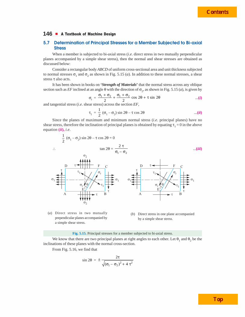
When a member is subjected to bi-axial stress (i.e. direct stress in two mutually perpendicularplanes accompanied by a simple shear stress), then the normal and shear stresses are obtained asdiscussed below:
Consider a rectangular body ABCD of uniform cross-sectional area and unit thickness subjectedto normal stresses σ1 and σ2 as shown in Fig. 5.15 (a). In addition to these normal stresses, a shearstress τ also acts.
It has been shown in books on ‘Strength of Materials’ that the normal stress across any obliquesection such as EF inclined at an angle θ with the direction of σ2, as shown in Fig. 5.15 (a), is given by
σt = 1 2 1 2 cos 2 sin 22 2
σ + σ σ + σ+ θ + τ θ ...(i)
and tangential stress (i.e. shear stress) across the section EF,
τ1 =1
2 (σ1 – σ2) sin 2θ – τ cos 2θ ...(ii)
Since the planes of maximum and minimum normal stress (i.e. principal planes) have noshear stress, therefore the inclination of principal planes is obtained by equating τ1 = 0 in the aboveequation (ii), i.e.
1
2 (σ1 – σ2) sin 2θ – τ cos 2θ = 0
∴ tan 2θ = 1 2
2
–
τσ σ
...(iii)
Fig. 5.15. Principal stresses for a member subjected to bi-axial stress.
We know that there are two principal planes at right angles to each other. Let θ1 and θ2 be theinclinations of these planes with the normal cross-section.
From Fig. 5.16, we find that
sin 2θ =2 2
1 2
2
( – ) 4
τ±σ σ + τ
(a) Direct stress in two mutuallyprependicular planes accompanied bya simple shear stress.
(b) Direct stress in one plane accompaniedby a simple shear stress.

Torsional and Bending Stresses in Machine Parts 147
Fig. 5.16
∴ sin 2θ1 =2 2
1 2
2
( – ) 4
τ+σ σ + τ
and sin 2θ2 =2 2
1 2
2–
( – ) 4
τ
σ σ + τ
Also cos 2θ = 1 2
2 21 2
–
( – ) 4
σ σ±σ σ + τ
∴ cos 2θ1 = 1 2
2 21 2
–
( – ) 4
σ σ+
σ σ + τ
and cos 2θ2 = 1 2
2 21 2
––
( – ) 4
σ σ
σ σ + τThe maximum and minimum principal stresses may now be obtained by substituting the values
of sin 2θ and cos 2θ in equation (i).∴ Maximum principal (or normal) stress,
σt1 = 2 21 21 2
1( – ) 4
2 2
σ + σ + σ σ + τ ...(iv)
and minimum principal (or normal) stress,
σt2 = 2 21 21 2
1– ( – ) 4
2 2
σ + σ σ σ + τ ...(v)
The planes of maximum shear stress are at right angles to each other and are inclined at 45° tothe principal planes. The maximum shear stress is given by one-half the algebraic difference betweenthe principal stresses, i.e.
τmax = 2 21 21 2
– 1( – ) 4
2 2t tσ σ
= σ σ + τ ...(vi)
A Boring mill.Note : This picture is given as additional information and is not a direct example of the current chapter.

148 A Textbook of Machine Design
Notes: 1. When a member is subjected to direct stress in one plane accompanied by a simple shear stress as shownin Fig. 5.15 (b), then the principal stresses are obtained by substituting σ2 = 0 in equation (iv), (v) and (vi).
∴ σt1 = 2 211
1( ) 4
2 2
σ ⎡ ⎤+ σ + τ⎣ ⎦
σt2 = 2 211
1– ( ) 4
2 2
σ ⎡ ⎤σ + τ⎣ ⎦
and τmax = 2 21
1( ) 4
2⎡ ⎤σ + τ⎣ ⎦
2. In the above expression of σt2, the value of 2 2
11
( ) 42⎡ ⎤σ + τ⎣ ⎦ is more than
1
2
σ. Therefore the nature
of σt2 will be opposite to that of σt1, i.e. if σt1 is tensile then σt2 will be compressive and vice-versa.
5.8 Application of Principal Stresses in Designing Machine MembersThere are many cases in practice, in which machine members are subjected to combined stresses
due to simultaneous action of either tensile or compressive stresses combined with shear stresses. Inmany shafts such as propeller shafts, C-frames etc., there are direct tensile or compressive stressesdue to the external force and shear stress due to torsion, which acts normal to direct tensile or com-pressive stresses. The shafts like crank shafts, are subjected simultaneously to torsion and bending. Insuch cases, the maximum principal stresses, due to the combination of tensile or compressive stresseswith shear stresses may be obtained.
The results obtained in the previous article may be written as follows:
1. Maximum tensile stress,
σt(max) = 2 21( ) 4
2 2t
tσ ⎡ ⎤+ σ + τ⎣ ⎦
2. Maximum compressive stress,
σc(max) = 2 21( ) 4
2 2c
cσ ⎡ ⎤+ σ + τ⎣ ⎦
3. Maximum shear stress,
τmax = 2 21( ) 4
2 t⎡ ⎤σ + τ⎣ ⎦
where σt = Tensile stress due to direct load and bending,
σc = Compressive stress, and
τ = Shear stress due to torsion.
Notes : 1. When τ = 0 as in the case of thin cylindrical shell subjected in internal fluid pressure, then
σt (max) = σt
2. When the shaft is subjected to an axial load (P) in addition to bending and twisting moments as in thepropeller shafts of ship and shafts for driving worm gears, then the stress due to axial load must be added to thebending stress (σb). This will give the resultant tensile stress or compressive stress (σt or σc) depending upon thetype of axial load (i.e. pull or push).
Example 5.13. A hollow shaft of 40 mm outer diameter and 25 mm inner diameter is subjectedto a twisting moment of 120 N-m, simultaneously, it is subjected to an axial thrust of 10 kN and abending moment of 80 N-m. Calculate the maximum compressive and shear stresses.
Solution. Given: do = 40 mm ; di = 25 mm ; T = 120 N-m = 120 × 103 N-mm ; P = 10 kN= 10 × 103 N ; M = 80 N-m = 80 × 103 N-mm
We know that cross-sectional area of the shaft,
A = 2 2 2 2 2( ) – ( ) (40) – (25) 766 mm4 4o id dπ π⎡ ⎤ ⎡ ⎤= =⎣ ⎦⎣ ⎦

Torsional and Bending Stresses in Machine Parts 149∴ Direct compressive stress due to axial thrust,
σo =310 10
766
P
A
×= = 13.05 N/mm2 = 13.05 MPa
Section modulus of the shaft,
Z =4 4 4 4
3( ) – ( ) (40) – (25)5325 mm
32 32 40o i
o
d d
d
⎡ ⎤ ⎡ ⎤π π= =⎢ ⎥ ⎢ ⎥⎣ ⎦⎣ ⎦
∴ Bending stress due to bending moment,
σb =380 10
5325
M
Z
×= = 15.02 N/mm2 = 15.02 MPa (compressive)
and resultant compressive stress,σc = σb + σo = 15.02 + 13.05 = 28.07 N/mm2 = 28.07 MPa
We know that twisting moment (T),
120 × 103 =4 4 4 4( ) – ( ) (40) – (25)
10 65016 16 40
o i
o
d d
d
⎡ ⎤ ⎡ ⎤π π× τ = × τ = τ⎢ ⎥ ⎢ ⎥⎣ ⎦⎣ ⎦
∴ τ = 120 × 103/10 650 = 11.27 N/mm2 = 11.27 MPa
Maximum compressive stressWe know that maximum compressive stress,
σc(max) = 2 21( ) 4
2 2c
cσ ⎡ ⎤+ σ + τ⎣ ⎦
= 2 228.07 1(28.07) 4 (11.27)
2 2⎡ ⎤+ +⎣ ⎦
= 14.035 + 18 = 32.035 MPa Ans.Maximum shear stress
We know that maximum shear stress,
τmax =2 2 2 21 1
2 2( ) 4 (28.07) 4 (11.27) 18 MPac
⎡ ⎤ ⎡ ⎤σ + τ = + =⎣ ⎦⎣ ⎦ Ans.
Example 5.14. A shaft, as shown in Fig. 5.17, is subjected to a bending load of 3 kN, pure torqueof 1000 N-m and an axial pulling force of 15 kN.
Calculate the stresses at A and B.
Solution. Given : W = 3 kN = 3000 N ;T = 1000 N-m = 1 × 10⁶ N-mm ; P = 15 kN= 15 × 103 N ; d = 50 mm; x = 250 mm
We know that cross-sectional area of the shaft,
A =4
π × d 2
= 4
π (50)2 = 1964 mm2
∴ Tensile stress due to axial pulling at points A and B,
σo =315 10
1964
P
A
×= = 7.64 N/mm2 = 7.64 MPa
Bending moment at points A and B,
M = W.x = 3000 × 250 = 750 × 103 N-mm
Fig. 5.17
150 A Textbook of Machine Design
Section modulus for the shaft,
Z =32
π × d3 =
32
π (50)3
= 12.27 × 103 mm3
∴ Bending stress at points A and B,
σb =3
3
750 10
12.27 10
M
Z
×=×
= 61.1 N/mm2 = 61.1 MPa
This bending stress is tensile at point A andcompressive at point B.
∴ Resultant tensile stress at point A, σA = σb + σo = 61.1 + 7.64 = 68.74 MPa
and resultant compressive stress at point B, σB = σb – σo = 61.1 – 7.64 = 53.46 MPaWe know that the shear stress at points A and B due to the torque transmitted,
τ =6
3 3
16 16 1 10
(50)
T
d
× ×=π π
= 40.74 N/mm2 = 40.74 MPa ... 3
16
π⎛ ⎞= × τ ×⎜ ⎟⎝ ⎠Q T d
Stresses at point AWe know that maximum principal (or normal) stress at point A,
σA(max) = 2 2AA
1( ) 4
2 2
σ ⎡ ⎤+ σ + τ⎣ ⎦
= 2 268.74 1(68.74) 4 (40.74)
2 2⎡ ⎤+ +⎣ ⎦
= 34.37 + 53.3 = 87.67 MPa (tensile) Ans.Minimum principal (or normal) stress at point A,
σA(min) = 2 2AA
1– ( ) 4
2 2
σ ⎡ ⎤σ + τ⎣ ⎦ = 34.37 – 53.3 = – 18.93 MPa
= 18.93 MPa (compressive ) Ans.and maximum shear stress at point A,
τA(max) = 2 2 2 21 1A2 2
( ) 4 (68.74) 4 (40.74)⎡ ⎤ ⎡ ⎤σ + τ = +⎣ ⎦⎣ ⎦
= 53.3 MPa Ans.
Stresses at point B
We know that maximum principal (or normal) stress at point B,
σB(max) = 2 2BB
1( ) 4
2 2
σ ⎡ ⎤+ σ + τ⎣ ⎦
= 2 253.46 1(53.46) 4 (40.74)
2 2⎡ ⎤+ +⎣ ⎦
= 26.73 + 48.73 = 75.46 MPa (compressive) Ans.
Note : This picture is given as additional information andis not a direct example of the current chapter.
This picture shows a machine component inside acrane

Torsional and Bending Stresses in Machine Parts 151Minimum principal (or normal) stress at point B,
σB(min) = B 2 2B
1– ( ) 4
2 2
σ ⎡ ⎤σ + τ⎣ ⎦
= 26.73 – 48.73 = – 22 MPa
= 22 MPa (tensile) Ans.
and maximum shear stress at point B,
τB(max) = 2 2 2 21 1B2 2
( ) 4 (53.46) 4 (40.74)⎡ ⎤ ⎡ ⎤σ + τ = +⎣ ⎦⎣ ⎦
= 48.73 MPa Ans.
Example 5.15. An overhang crank with pin and shaft is shown in Fig. 5.18. A tangential loadof 15 kN acts on the crank pin. Determine the maximum principal stress and the maximum shearstress at the centre of the crankshaft bearing.
Fig. 5.18
Solution. Given : W = 15 kN = 15 × 103 N ; d = 80 mm ; y = 140 mm ; x = 120 mm
Bending moment at the centre of the crankshaft bearing,
M = W × x = 15 × 103 × 120 = 1.8 × 10⁶ N-mm
and torque transmitted at the axis of the shaft,
T = W × y = 15 × 103 × 140 = 2.1 × 10⁶ N-mm
We know that bending stress due to the bending moment,
σb = 3
32M M
Z d=
π... 3
32
π⎛ ⎞= ×⎜ ⎟⎝ ⎠QZ d
=6
3
32 1.8 10
(80)
× ×π
= 35.8 N/mm2 = 35.8 MPa
and shear stress due to the torque transmitted,
τ =6
3 3
16 16 2.1 10
(80)
T
d
× ×=π π
= 20.9 N/mm2 = 20.9 MPa
Maximum principal stressWe know that maximum principal stress,
σt(max) = 2 21( ) 4
2 2t
tσ ⎡ ⎤+ σ + τ⎣ ⎦
= 2 235.8 1(35.8) 4 (20.9)
2 2⎡ ⎤+ +⎣ ⎦ ... (Substituting σt = σb)
= 17.9 + 27.5 = 45.4 MPa Ans.

152 A Textbook of Machine Design
Maximum shear stressWe know that maximum shear stress,
τmax = 2 2 2 21 12 2
( ) 4 (35.8) 4 (20.9)t⎡ ⎤ ⎡ ⎤σ + τ = +⎣ ⎦⎣ ⎦
= 27.5 MPa Ans.
5.9 Theories of Failure Under Static LoadIt has already been discussed in the previous chapter that strength of machine members is based
upon the mechanical properties of the materials used. Since these properties are usually determinedfrom simple tension or compression tests, therefore, predicting failure in members subjected to uni-axial stress is both simple and straight-forward. But the problem of predicting the failure stresses formembers subjected to bi-axial or tri-axial stresses is much more complicated. In fact, the problem isso complicated that a large number of different theories have been formulated. The principal theoriesof failure for a member subjected to bi-axial stress are as follows:
1. Maximum principal (or normal) stress theory (also known as Rankine’s theory).2. Maximum shear stress theory (also known as Guest’s or Tresca’s theory).3. Maximum principal (or normal) strain theory (also known as Saint Venant theory).4. Maximum strain energy theory (also known as Haigh’s theory).5. Maximum distortion energy theory (also known as Hencky and Von Mises theory).Since ductile materials usually fail by yielding i.e. when permanent deformations occur in the
material and brittle materials fail by fracture, therefore the limiting strength for these two classes ofmaterials is normally measured by different mechanical properties. For ductile materials, the limitingstrength is the stress at yield point as determined from simple tension test and it is, assumed to beequal in tension or compression. For brittle materials, the limiting strength is the ultimate stress intension or compression.
5.10 Maximum Principal or Normal Stress Theory (Rankine’s Theory)According to this theory, the failure or yielding occurs at a point in a member when the maximum
principal or normal stress in a bi-axial stress system reaches the limiting strength of the material in asimple tension test.
Since the limiting strength for ductile materials is yield point stress and for brittle materials(which do not have well defined yield point) the limiting strength is ultimate stress, therefore according
Pig iron is made from iron ore in a blast furnace. It is a brittle form of iron that contains 4-5 per cent carbon.
Coke
Waste gasesare removed
Hot airblasted intofurnace
Molten slag removed
Iron ore
Pig iron andscrap steelare pouredinto converter
Oxygen isblown intomolten metal
Converter pours outmolten steel
Molten steel fluid can be pouredinto moulds or cast while fuild
Oxygen burns off carbon toturn the pig iron into steelMolten pig iron
Ladle
Iron
Limestone
Mixed rawmaerials
The molten steel canthen be tapped off.
Note : This picture is given as additional information and is not a direct example of the current chapter.
Torsional and Bending Stresses in Machine Parts 153to the above theory, taking factor of safety (F.S.) into consideration, the maximum principal or normalstress (σt1) in a bi-axial stress system is given by
σt1 =. .yt
F S
σ, for ductile materials
=. .u
F S
σ, for brittle materials
where σyt = Yield point stress in tension as determined from simple tensiontest, and
σu = Ultimate stress.Since the maximum principal or normal stress theory is based on failure in tension or compression
and ignores the possibility of failure due to shearing stress, therefore it is not used for ductile materials.However, for brittle materials which are relatively strong in shear but weak in tension or compression,this theory is generally used.Note : The value of maximum principal stress (σt1) for a member subjected to bi-axial stress system may bedetermined as discussed in Art. 5.7.
5.11 Maximum Shear Stress Theory (Guest’s or Tresca’s Theory)According to this theory, the failure or yielding occurs at a point in a member when the maximum
shear stress in a bi-axial stress system reaches a value equal to the shear stress at yield point in asimple tension test. Mathematically,
τmax = τyt /F.S. ...(i)where τmax = Maximum shear stress in a bi-axial stress system,
τyt = Shear stress at yield point as determined from simple tension test,and
F.S. = Factor of safety.
Since the shear stress at yield point in a simple tension test is equal to one-half the yield stressin tension, therefore the equation (i) may be written as
τmax =2 . .
yt
F S
σ×
This theory is mostly used for designing members of ductile materials.Note: The value of maximum shear stress in a bi-axial stress system (τmax) may be determined as discussed inArt. 5.7.
5.12 Maximum Principal Strain Theory (Saint Venant’s Theory)According to this theory, the failure or yielding occurs at a point in a member when the maximum
principal (or normal) strain in a bi-axial stress system reaches the limiting value of strain (i.e. strain atyield point) as determined from a simple tensile test. The maximum principal (or normal) strain in abi-axial stress system is given by
εmax = 1 2–.
t t
E m E
σ σ
∴ According to the above theory,
εmax = 1 2–. . .
ytt t
E m E E F S
σσ σ= ε =
×...(i)
where σt1 and σt2 = Maximum and minimum principal stresses in a bi-axial stress system,ε = Strain at yield point as determined from simple tension test,
1/m = Poisson’s ratio,E = Young’s modulus, and
F.S. = Factor of safety.

154 A Textbook of Machine Design
From equation (i), we may write that
21 –
. .ytt
t m F S
σσσ =
This theory is not used, in general, because it only gives reliable results in particular cases.
5.13 Maximum Strain Energy Theory (Haigh’s Theory)According to this theory, the failure or yielding occurs at a point in a member when the strain
energy per unit volume in a bi-axial stress system reaches the limiting strain energy (i.e. strain energyat the yield point ) per unit volume as determined from simple tension test.
We know that strain energy per unit volume in a bi-axial stress system,
U1 =2 2 1 2
1 221
( ) ( ) –2
t tt tE m
σ × σ⎡ ⎤σ + σ⎢ ⎥⎣ ⎦and limiting strain energy per unit volume for yielding as determined from simple tension test,
U2 =2
1
2 . .yt
E F S
σ⎛ ⎞⎜ ⎟⎝ ⎠
According to the above theory, U1 = U2.
∴2
2 2 1 21 2
21 1( ) ( ) –
2 2 . .ytt t
t tE m E F S
σ⎛ ⎞σ × σ⎡ ⎤σ + σ = ⎜ ⎟⎢ ⎥⎣ ⎦ ⎝ ⎠
or (σt1)2 + (σt2)2 –
21 22
. .ytt t
m F S
σ⎛ ⎞σ × σ= ⎜ ⎟⎝ ⎠
This theory may be used for ductile materials.
5.14 Maximum Distortion Energy Theory (Hencky and Von Mises Theory)According to this theory, the failure or yielding occurs at a point in a member when the distortion
strain energy (also called shear strain energy) per unit volume in a bi-axial stress system reaches thelimiting distortion energy (i.e. distortion energy at yield point) per unit volume as determined from asimple tension test. Mathematically, the maximum distortion energy theory for yielding is expressedas
(σt1)2 + (σt2)
2 – 2σt1 × σt2 = 2
. .yt
F S
σ⎛ ⎞⎜ ⎟⎝ ⎠
This theory is mostly used for ductile materials in place of maximum strain energy theory.Note: The maximum distortion energy is the difference between the total strain energy and the strain energy dueto uniform stress.
This double-decker A 380 has a passenger capacity of 555. Its engines and parts should be robustwhich can bear high torsional and variable stresses.

Torsional and Bending Stresses in Machine Parts 155Example 5.16. The load on a bolt consists of an axial pull of 10 kN together with a transverse
shear force of 5 kN. Find the diameter of bolt required according to1. Maximum principal stress theory; 2. Maximum shear stress theory; 3. Maximum principal
strain theory; 4. Maximum strain energy theory; and 5. Maximum distortion energy theory.
Take permissible tensile stress at elastic limit = 100 MPa and poisson’s ratio = 0.3.
Solution. Given : Pt1 = 10 kN ; Ps = 5 kN ; σt(el) = 100 MPa = 100 N/mm2 ; 1/m = 0.3
Let d = Diameter of the bolt in mm.
∴ Cross-sectional area of the bolt,
A =4
π × d2 = 0.7854 d 2 mm2
We know that axial tensile stress,
σ1 =21
2 2
10 12.73kN/mm
0.7854tP
A d d= =
and transverse shear stress,
τ =2
2 2
5 6.365kN/mm
0.7854sP
A d d= =
1. According to maximum principal stress theoryWe know that maximum principal stress,
σt1 = 2 21 21 2
1( – ) 4
2 2
σ + σ ⎡ ⎤+ σ σ + τ⎣ ⎦
= 2 211
1( ) 4
2 2
σ ⎡ ⎤+ σ + τ⎣ ⎦ ...(Q σ2 = 0)
=2 2
2 2 2
12.73 1 12.73 6.3654
22 d d d
⎡ ⎤⎛ ⎞ ⎛ ⎞⎢ ⎥+ +⎜ ⎟ ⎜ ⎟⎢ ⎥⎝ ⎠ ⎝ ⎠⎣ ⎦
= 2 2
6.365 1 6.3654 4
2d d⎡ ⎤+ × +⎣ ⎦
= 2 22 2 2
6.365 1 15.365 15 3651 4 4 kN/mm N/mm
2d d d
⎡ ⎤+ + = =⎢ ⎥⎣ ⎦According to maximum principal stress theory,
σt1 = σt(el) or 2
15 365100
d=
∴ d 2 = 15 365/100 = 153.65 or d = 12.4 mm Ans.2. According to maximum shear stress theory
We know that maximum shear stress,
τmax = 2 2 2 21 11 2 12 2
( – ) 4 ( ) 4⎡ ⎤ ⎡ ⎤σ σ + τ = σ + τ⎣ ⎦ ⎣ ⎦ ...(Q σ2 = 0)
=2 2
2 2 2
1 12.73 6.365 1 6.3654 4 4
2 2d d d
⎡ ⎤⎛ ⎞ ⎛ ⎞⎢ ⎥ ⎡ ⎤+ = × +⎜ ⎟ ⎜ ⎟ ⎣ ⎦⎢ ⎥⎝ ⎠ ⎝ ⎠⎣ ⎦
= 2 22 2
9 9000kN/mm N/mm
d d=
According to maximum shear stress theory,
τmax =( )
2t elσ
or 2
9000 10050
2d= =
∴ d 2 = 9000 / 50 = 180 or d = 13.42 mm Ans.

156 A Textbook of Machine Design
3. According to maximum principal strain theoryWe know that maximum principal stress,
σt1 =2 21
1 2
1 15 365( ) 4
2 2 d
σ ⎡ ⎤+ σ + τ =⎣ ⎦ ...(As calculated before)
and minimum principal stress,
σt2 = 2 211
1– ( ) 4
2 2
σ ⎡ ⎤σ + τ⎣ ⎦
=2 2
2 2 2
12.73 1 12.73 6.365– 4
22 d d d
⎡ ⎤⎛ ⎞ ⎛ ⎞⎢ ⎥+⎜ ⎟ ⎜ ⎟⎢ ⎥⎝ ⎠ ⎝ ⎠⎣ ⎦
= 2 2
6.365 1 6.365– 4 4
2d d⎡ ⎤× +⎣ ⎦
= 22 2
6.365 – 2.6351 – 2 kN/mm⎡ ⎤ =⎣ ⎦
d d
22
– 2635N/mm=
dWe know that according to maximum principal strain theory,
1 2–t t
E mE
σ σ = ( )t el
E
σor 2
1 ( )– tt t elm
σσ = σ
∴2 2
15 365 2635 0.3100
d d
×+ = or 2
16 156100
d=
d 2 =16 156 / 100 = 161.56 or d = 12.7 mm Ans.4. According to maximum strain energy theory
We know that according to maximum strain energy theory,
(σt1)2 + (σt2)2 – 1 22 t t
m
σ × σ = [σt(el)]
2
2 22
2 2 2 2
15 365 – 2635 15 365 – 2635– 2 0.3 (100)
d d d d
⎡ ⎤ ⎡ ⎤+ × × × =⎢ ⎥ ⎢ ⎥⎣ ⎦ ⎣ ⎦6 6 6
34 4 4
236 10 6.94 10 24.3 1010 10
d d d
× × ×+ + = ×
4 4 4
23 600 694 24301
d d d+ + = or
4
26 7241
d=
∴ d 4 = 26 724 or d = 12.78 mm Ans.5. According to maximum distortion energy theory
According to maximum distortion energy theory,
(σt1)2 + (σt2)
2 – 2σt1 × σt2= [σt(el)]2
2 22
2 2 2 2
15 365 – 2635 15 365 – 2635– 2 (100)
d d d d
⎡ ⎤ ⎡ ⎤+ × × =⎢ ⎥ ⎢ ⎥⎣ ⎦ ⎣ ⎦6 6 6
34 4 4
236 10 6.94 10 80.97 1010 10
d d d
× × ×+ + = ×
4 4 4
23 600 694 80971
d d d+ + = or 4
32 3911
d=
∴ d4 = 32 391 or d = 13.4 mm Ans.
Front view of a jet engine. The rotors un-dergo high torsional and bending stresses.

Torsional and Bending Stresses in Machine Parts 157Example 5.17. A cylindrical shaft made of steel of yield strength 700 MPa is subjected to static
loads consisting of bending moment 10 kN-m and a torsional moment 30 kN-m. Determine the diameterof the shaft using two different theories of failure, and assuming a factor of safety of 2. Take E = 210GPa and poisson's ratio = 0.25.
Solution. Given : σyt = 700 MPa = 700 N/mm2 ; M = 10 kN-m = 10 × 106 N-mm ; T = 30 kN-m= 30 × 106 N-mm ; F.S. = 2 ; E = 210 GPa = 210 × 103 N/mm2 ; 1/m = 0.25
Let d = Diameter of the shaft in mm.First of all, let us find the maximum and minimum principal stresses.We know that section modulus of the shaft
Z =32
π × d 3 = 0.0982 d3 mm3
∴ Bending (tensile) stress due to the bending moment,
σ1 =6 6
23 3
10 10 101.8 10N/mm
0.0982
M
Z d d
× ×= =
and shear stress due to torsional moment,
τ =6 6
23 3 3
16 16 30 10 152.8 10N/mm
T
d d d
× × ×= =π π
We know that maximum principal stress,
σt1 = 2 21 21 2
1( – ) 4
2 2
σ + σ ⎡ ⎤+ σ σ + τ⎣ ⎦
= 2 211
1( ) 4
2 2
σ ⎡ ⎤+ σ + τ⎣ ⎦ ...(Q σ2 = 0)
=
2 26 6 6
3 3 3
101.8 10 1 101.8 10 152.8 104
22d d d
⎡ ⎤⎛ ⎞ ⎛ ⎞× × ×⎢ ⎥+ +⎜ ⎟ ⎜ ⎟⎢ ⎥⎝ ⎠ ⎝ ⎠⎣ ⎦
=6 6
2 23 3
50.9 10 1 10(101.8) 4 (152.8)
2d d
× ⎡ ⎤+ × +⎣ ⎦
=6 6 6
23 3 3
50.9 10 161 10 211.9 10N/mm
d d d
× × ×+ =
and minimum principal stress,
σt2 = 2 21 21 2
1– ( – ) 4
2 2
σ + σ ⎡ ⎤σ σ + τ⎣ ⎦
= 2 211
1– ( ) 4
2 2
σ ⎡ ⎤σ + τ⎣ ⎦ ...(Q σ2 = 0)
=6 6 6
23 3 3
50.9 10 161 10 – 110.1 10– N/mm
d d d
× × ×=
Let us now find out the diameter of shaft (d) by considering the maximum shear stress theoryand maximum strain energy theory.
1. According to maximum shear stress theoryWe know that maximum shear stress,
τmax =6 6 6
1 23 3 3
1 211.9 10 110.1 10 161 10
2 2t t
d d d
⎡ ⎤σ − σ × × ×= + =⎢ ⎥
⎣ ⎦We also know that according to maximum shear stress theory,
τmax =2 . .
yt
F S
σ or
6
3
161 10 700175
2 2d
× = =×
∴ d 3 = 161 × 106 / 175 = 920 × 103 or d = 97.2 mm Ans.

158 A Textbook of Machine Design
Note: The value of maximum shear stress (τmax) may also be obtained by using the relation,
τmax = 2 2112
( ) 4⎡ ⎤σ + τ⎣ ⎦
=
2 26 6
3 3
1 101.8 10 152.8 104
2 d d
⎡ ⎤⎛ ⎞ ⎛ ⎞× ×⎢ ⎥+⎜ ⎟ ⎜ ⎟⎢ ⎥⎝ ⎠ ⎝ ⎠⎣ ⎦
=6
2 23
1 10(101.8) 4 (152.8)
2 d⎡ ⎤× +⎣ ⎦
=6 6
23 3
1 10 161 10322 N/mm
2 d d
×× × = ...(Same as before)
2. According to maximum strain energy theoryWe know that according to maximum strain energy theory,
2
2 2 1 21 2
21 1( ) ( ) –
2 2 . .ytt t
t tE m E F S
σ⎛ ⎞σ × σ⎡ ⎤σ + σ = ⎜ ⎟⎢ ⎥⎣ ⎦ ⎝ ⎠
or (σt1)2 + (σt2)
2 – 2
1 22
. .ytt t
m F S
σ⎛ ⎞σ × σ= ⎜ ⎟⎝ ⎠
2 2 26 6 6 6
3 3 3 3
211.9 10 – 110.1 10 211.9 10 – 110.1 10 700– 2 0.25
2d d d d
⎡ ⎤ ⎡ ⎤× × × × ⎛ ⎞+ × × × = ⎜ ⎟⎢ ⎥ ⎢ ⎥⎝ ⎠⎣ ⎦ ⎣ ⎦
or 12 12 12
6 6 6
44 902 10 12 122 10 11 665 10122 500
d d d
× × ×+ + =12
6
68 689 10122 500
d
× =
∴ d 6 = 68 689 × 1012/122 500 = 0.5607 × 10¹² or d = 90.8 mm Ans.Example 5.18. A mild steel shaft of 50 mm diameter is subjected to a bending moment of 2000
N-m and a torque T. If the yield point of the steel in tension is 200 MPa, find the maximum value ofthis torque without causing yielding of the shaft according to 1. the maximum principal stress; 2. themaximum shear stress; and 3. the maximum distortion strain energy theory of yielding.
Solution. Given: d = 50 mm ; M = 2000 N-m = 2 × 10⁶ N-mm ; σyt = 200 MPa = 200 N/mm2
Let T = Maximum torque without causing yielding of the shaft, in N-mm.
1. According to maximum principal stress theoryWe know that section modulus of the shaft,
Z =32
π × d3 =
32
π (50)3 = 12 273 mm3
∴ Bending stress due to the bending moment,
σ1 =6
22 10163 N/mm
12 273
M
Z
×= =
and shear stress due to the torque,
τ = 3 3
16 16
(50)
T T
d=
π π = 0.0407 × 10⁻³ T N/mm2
... 3
16
π⎡ ⎤= × τ ×⎢ ⎥⎣ ⎦QT d
We know that maximum principal stress,
σt1 = 2 211
1( ) 4
2 2
σ ⎡ ⎤+ σ + τ⎣ ⎦
= 2 –3 2163 1(163) 4 (0.0407 10 )
2 2T⎡ ⎤+ + ×⎣ ⎦

Torsional and Bending Stresses in Machine Parts 159
= –9 2 281.5 6642.5 1.65 10 N/mmT+ + ×Minimum principal stress,
σt2 = 2 211
1– ( ) 4
2 2
σ ⎡ ⎤σ + τ⎣ ⎦
= 2 –3 2163 1– (163) 4 (0.0407 10 )
2 2T⎡ ⎤+ ×⎣ ⎦
= –9 2 281.5 – 6642.5 1.65 10 N/mmT+ ×and maximum shear stress,
τmax = 2 2 2 –3 21 112 2
( ) 4 (163) 4 (0.0407 10 )T⎡ ⎤ ⎡ ⎤σ + τ = + ×⎣ ⎦⎣ ⎦
= –9 2 26642.5 1.65 10 N/mmT+ ×We know that according to maximum principal stress theory,
σt1 = σyt ...(Taking F.S. = 1)
∴ –9 281.5 6642.5 1.65 10 200T+ + × = 6642.5 + 1.65 + 10–9 T 2 = (200 – 81.5)2 = 14 042
T 2 = 9–9
14 042 – 6642.54485 10
1.65 10= ×
×or T = 2118 × 103 N-mm = 2118 N-m Ans.2. According to maximum shear stress theory
We know that according to maximum shear stress theory,
τmax = τyt = 2ytσ
∴ –9 2 2006642.5 1.65 10 100
2T+ × = =
6642.5 + 1.65 × 10⁻⁹ T 2 = (100)2 = 10 000
T 2 = 9
–9
10 000 – 6642.52035 10
1.65 10= ×
×∴ T = 1426 × 103 N-mm = 1426 N-m Ans.
3. According to maximum distortion strain energy theoryWe know that according to maximum distortion strain energy theory (σt1)2 + (σt2)
2 – σt1 × σt2 = (σyt)2
2 2–9 2 –9 281.5 6642.5 1.65 10 81.5 – 6642.5 1.65 10T T⎡ ⎤ ⎡ ⎤+ + × + + ×⎣ ⎦ ⎣ ⎦
–9 2 –9 2 2– 81.5 6642.5 1.65 10 81.5 – 6642.5 1.65 10 (200)T T⎡ ⎤ ⎡ ⎤+ + × + × =⎣ ⎦ ⎣ ⎦
2 –9 2 2 –9 2 22 (81.5) 6642.5 1.65 10 – (81.5) – 6642.5 1.65 10 (200)T T⎡ ⎤ ⎡ ⎤+ + × + × =⎣ ⎦ ⎣ ⎦
(81.5)2 + 3 × 6642.5 + 3 × 1.65 × 10–9 T 2 = (200)2
26 570 + 4.95 × 10⁻⁹ T 2 = 40 000
T 2 = 9–9
40 000 – 26 5702713 10
4.95 10= ×
×∴ T = 1647 × 103 N-mm = 1647 N-m Ans.

160 A Textbook of Machine Design
5.15 Eccentric Loading - Direct and Bending Stresses CombinedAn external load, whose line of action is parallel but does not coincide with the centroidal axis
of the machine component, is known as an eccentric load. The distance between the centroidal axisof the machine component and the eccentric load is called eccentricity and is generally denoted by e.The examples of eccentric loading, from the subject point of view, are C-clamps, punching machines,brackets, offset connecting links etc.
Fig. 5.19. Eccentric loading.
Consider a short prismatic bar subjected to a compressive load P acting at an eccentricity of e asshown in Fig. 5.19 (a).
Let us introduce two forces P1 and P2 along the centre line or neutral axis equal in magnitude toP, without altering the equilibrium of the bar as shown in Fig. 5.19 (b). A little consideration willshow that the force P1 will induce a direct compressive stress over the entire cross-section of the bar,as shown in Fig. 5.19 (c).
The magnitude of this direct compressive stress is given by
σo = 1P
A or
P
A, where A is the cross-sectional area of the bar.
The forces P1 and P2 will form a couple equal to P × e which will cause bending stress. Thisbending stress is compressive at the edge AB and tensile at the edge CD, as shown in Fig. 5.19 (d).The magnitude of bending stress at the edge AB is given by
σb =. . cP e y
I (compressive)
and bending stress at the edge CD,
σb =. . tP e y
I (tensile)

Torsional and Bending Stresses in Machine Parts 161where yc and yt = Distances of the extreme fibres on the compressive and tensile sides,
from the neutral axis respectively, andI = Second moment of area of the section about the neutral axis i.e.
Y-axis.According to the principle of superposition, the maximum or the resultant compressive stress at
the edge AB,
σc =. .
+ =cP e y P
I A* + = σ + σb o
M P
Z Aand the maximum or resultant tensile stress at the edge CD,
σt =. .
– –tb o
P e y P M P
I A Z A= = σ − σ
The resultant compressive and tensile stress diagram is shown in Fig. 5.19 (e).
Notes: 1. When the member is subjected to a tensile load, then theabove equations may be used by interchanging the subscripts c and t.
2. When the direct stress σo is greater than or equal to bendingstress σb, then the compressive stress shall be present all over thecross-section.
3. When the direct stress σo is less than the bending stress σb,then the tensile stress will occur in the left hand portion of the cross-section and compressive stress on the right hand portion of the cross-section. In Fig. 5.19, the stress diagrams are drawn by taking σo lessthan σb.
In case the eccentric load acts with eccentricity about two axes,as shown in Fig. 5.20, then the total stress at the extreme fibre
= XX YY
. .. . yxP e yP P e x
A I I± ±
Fig. 5.20. Eccentric load witheccentricity about two axes.
* We know that bending moment, M = P.e and section modulus, Z = orc t
I I
y y y=
∴ Bending stress, σb = M / Z
In a gas-turbine system, a compressor forces air into a combustion chamber. There, it mixes with fuel.The mixture is ignited by a spark. Hot gases are produced when the fuel burns. They expand and drivea series of fan blades called a turbine.
Compressor
Fuel injector
Fuel line
Spark plug
Air in
Combustion chamber
Turbine shaft
Turbines
Exhaust
Note : This picture is given as additional information and is not a direct example of the current chapter.
162 A Textbook of Machine Design
Fig. 5.22
Fig. 5.21
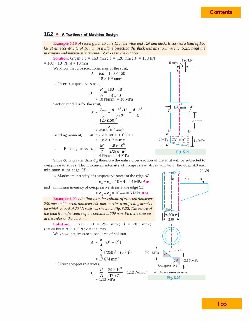
Example 5.19. A rectangular strut is 150 mm wide and 120 mm thick. It carries a load of 180kN at an eccentricity of 10 mm in a plane bisecting the thickness as shown in Fig. 5.21. Find themaximum and minimum intensities of stress in the section.
Solution. Given : b = 150 mm ; d = 120 mm ; P = 180 kN= 180 × 103 N ; e = 10 mm
We know that cross-sectional area of the strut,A = b.d = 150 × 120
= 18 × 103 mm2
∴ Direct compressive stress,
σo =3
3
180 10
18 10
P
A
×=×
= 10 N/mm2 = 10 MPaSection modulus for the strut,
Z =3 2
YY . /12 .
/ 2 6
I d b d b
y b= =
=2120 (150)
6= 450 × 103 mm3
Bending moment, M = P.e = 180 × 103 × 10= 1.8 × 10⁶ N-mm
∴ Bending stress, σb =6
3
1.8 10
450 10
M
Z
×=×
= 4 N/mm2 = 4 MPaSince σo is greater than σb, therefore the entire cross-section of the strut will be subjected to
compressive stress. The maximum intensity of compressive stress will be at the edge AB andminimum at the edge CD.
∴ Maximum intensity of compressive stress at the edge AB
= σo + σb = 10 + 4 = 14 MPa Ans.and minimum intensity of compressive stress at the edge CD
= σo – σb = 10 – 4 = 6 MPa Ans.Example 5.20. A hollow circular column of external diameter
250 mm and internal diameter 200 mm, carries a projecting bracketon which a load of 20 kN rests, as shown in Fig. 5.22. The centre ofthe load from the centre of the column is 500 mm. Find the stressesat the sides of the column.
Solution. Given : D = 250 mm ; d = 200 mm ;P = 20 kN = 20 × 103 N ; e = 500 mm
We know that cross-sectional area of column,
A =4
π (D2 – d2)
= 4
π [(250)2 – (200)2]
= 17 674 mm2
∴ Direct compressive stress,
σo =3
220 101.13 N/mm
17 674
P
A
×= =
= 1.13 MPa

Torsional and Bending Stresses in Machine Parts 163
Wind turbine.
Note : This picture is given as additional information andis not a direct example of the current chapter.
TransmissionPosit ioninggears
Turbine head
Controlelectronicsadjust positionof wind turbinehead
Internal laddersallow access towind turbinehead
Turbine blade
Vents for coolingair
Drive shaft
Section modulus for the column,
Z =
4 4–64
/ 2
D dI
y D
π ⎡ ⎤⎣ ⎦= =
4 4(250) – (200)64
250 / 2
π ⎡ ⎤⎣ ⎦
=905.8 × 103 mm3
Bending moment,M = P.e
= 20 × 103 × 500=10 × 106 N-mm
∴ Bending stress,
σb =6
3
10 10
905.8 10
M
Z
×=×
= 11.04 N/mm2
= 11.04 MPa
Since σo is less than σb, therefore righthand side of the column will be subjected tocompressive stress and the left hand side of thecolumn will be subjected to tensile stress.
∴ Maximum compressive stress,
σc = σb + σo = 11.04 + 1.13
= 12.17 MPa Ans.
and maximum tensile stress,
σt = σb – σo = 11.04 – 1.13 = 9.91 MPa Ans.Example 5.21. A masonry pier of width 4 m and thickness 3 m, supports a load of 30 kN as
shown in Fig. 5.23. Find the stresses developed at each corner of the pier.
Solution. Given: b = 4 m ; d = 3 m ; P = 30 kN ; ex = 0.5 m ; ey = 1 m
We know that cross-sectional area of the pier,
A = b × d = 4 × 3 = 12 m2
Moment of inertia of the pier about X-axis,
IXX = 3 3
4. 4 39 m
12 12
b d ×= =
and moment of inertia of the pier about Y-axis,
IYY = 3 3
4. 3 416 m
12 12
d b ×= =
Distance between X-axis and the corners A and B,
x = 3 / 2 = 1.5 mDistance between Y-axis and the corners A and C,
y = 4 / 2 = 2 m
We know that stress at corner A,
σA =XX YY
. .. . yxP e yP e xP
A I I+ + ... [Q At A, both x and y are +ve]
Fig. 5.23

164 A Textbook of Machine Design
=30 30 0.5 1.5 30 1 2
12 9 16
× × × ×+ +
= 2.5 + 2.5 + 3.75 = 8.75 kN/m2 Ans.Similarly stress at corner B,
σB =XX YY
. .. .– yx
P e yP e xP
A I I+ ... [Q At B, x is +ve and y is –ve]
=30 30 0.5 1.5 30 1 2
–12 9 16
× × × ×+
= 2.5 + 2.5 – 3.75 = 1.25 kN/m2 Ans.Stress at corner C,
σC =XX YY
. .. .– yx
P e yP e xP
A I I+ ... [At C, x is –ve and y is +ve]
=30 30 0.5 1.5 30 1 2
–12 9 16
× × × ×+
= 2.5 – 2.5 + 3.75 = 3.75 kN/m2 Ans.and stress at corner D,
σD =XX YY
. .. .– – yx
P e yP e xP
A I I... [At D, both x and y are – ve]
=30 30 0.5 1.5 30 1 2
– –12 9 16
× × × ×
= 2.5 – 2.5 – 3.75 = – 3.75 kN/m2 = 3.75 kN/m2 (tensile) Ans.
Example 5.22. A mild steel link, as shown in Fig. 5.24 by full lines, transmits a pull of 80 kN.Find the dimensions b and t if b = 3t.Assume the permissible tensile stress as70 MPa. If the original link is replacedby an unsymmetrical one, as shown bydotted lines in Fig. 5.24, having the samethickness t, find the depth b1, using thesame permissible stress as before.
Solution. Given : P = 80 kN= 80 × 103 N ; σt = 70 MPa = 70 N/mm2
When the link is in the position shown by full lines in Fig. 5.24, the area of cross-section,
A = b × t = 3 t × t = 3 t 2 ...(Q b = 3 t )
We know that tensile load (P),
80 × 103 = σt × A = 70 × 3 t2 = 210 t2
∴ t2 = 80 × 103 / 210 = 381 or t = 19.5 say 20 mm Ans.
and b = 3 t = 3 × 20 = 60 mm Ans.
When the link is in the position shown by dotted lines, it will be subjected to direct stress as wellas bending stress. We know that area of cross-section,
A1 = b1 × t
Fig. 5.24

Torsional and Bending Stresses in Machine Parts 165
Fig. 5.26
∴ Direct tensile stress,
σo =1
=×
P P
A b t
and bending stress, σb = 21
. 6 .
( )= =M P e P e
Z Z t b...
21( )
6
⎛ ⎞=⎜ ⎟
⎝ ⎠Q
t bZ
∴Total stress due to eccentric loading
= 21 1 11
6 . 61
.( )
⎛ ⎞σ + σ = + = +⎜ ⎟× ⎝ ⎠b o
P e P P e
b t t b bt b
Since the permissible tensile stress is the same as 70 N/mm2, therefore
70 =3 3
1
1 1 1
680 10 16 101
20 2
×× ×⎛ ⎞+ =⎜ ⎟×⎝ ⎠
b
b b b... 1Eccentricity,
2⎛ ⎞=⎜ ⎟⎝ ⎠Q
be
∴ b1 = 16 × 103 / 70 = 228.6 say 230 mm Ans.Example 5.23. A cast-iron link, as shown in Fig. 5.25, is to carry a load of 20 kN. If the tensile
and compressive stresses in the link are not to exceed 25 MPa and 80 MPa respectively, obtain thedimensions of the cross-section of the link at the middle of its length.
Fig. 5.25
Solution. Given : P = 20 kN = 20 × 103 N ; σt(max) = 25 MPa = 25 N/mm2 ; σc(max) = 80 MPa= 80 N/mm2
Since the link is subjected to eccentric loading, therefore therewill be direct tensile stress as well as bending stress. The bendingstress at the bottom of the link is tensile and in the upper portion iscompressive.
We know that cross-sectional area of the link,
A = 3a × a + 2 × 2
3
a × 2a
= 5.67 a2 mm2
∴ Direct tensile stress,
σo =3
22 2
20 10 3530N/mm
5.67
P
A a a
×= =
Now let us find the position of centre of gravity (or neutral axis) in order to find the bendingstresses.
Let y = Distance of neutral axis (N.A.) from the bottom of the link as shownin Fig. 5.26.
∴ y =
22
2
43 2 2
2 3 1.2 mm5.67
a aa a
aa
× + × ×=

166 A Textbook of Machine Design
Moment of inertia about N.A.,
33 2
2 2 2
2(2 )3 433 (1.2 – 0.5 ) 2 (2 – 1.2 )
12 12 3
a aa a aI a a a a a
⎡ ⎤×⎡ ⎤ ⎢ ⎥×= + + +⎢ ⎥ ⎢ ⎥⎣ ⎦ ⎣ ⎦
= (0.25 a4 + 1.47 a4) + 2 (0.44a4 + 0.85 a4) = 4.3 a4 mm4
Distance of N.A. from the bottom of the link,
yt = y = 1.2 a mm
Distance of N.A. from the top of the link,
yc = 3 a – 1.2 a = 1.8 a mm
Eccentricity of the load (i.e. distance of N.A. from the point of application of the load),
e = 1.2 a – 0.5 a = 0.7 a mm
We know that bending moment exerted on the section,
M = P.e = 20 × 103 × 0.7 a = 14 × 103 a N-mm
∴ Tensile stress in the bottom of the link,
σt =t
M
Z =
3
4 2
. 14 10 1.2 3907
/ 4.3
× ×= = =t
t
M yM a a
I y I a a
and compressive stress in the top of the link,
σc =3
4 2
. 14 10 1.8 5860
/ 4.3c
c c
M yM M a a
Z I y I a a
× ×= = = =
We know that maximum tensile stress [σt (max)],
25 = 2 2 2
3907 5860 9767t c
a a aσ + σ = + =
∴ a2 = 9767 / 25 = 390.7 or a = 19.76 mm ...(i)
and maximum compressive stress [σc(max)],
80 = σc – σ0 = 2 2 2
5860 3530 2330–
a a a=
∴ a2 = 2330 / 80 = 29.12 or a = 5.4 mm ...(ii)
We shall take the larger of the two values, i.e.
a = 19.76 mm Ans.
Example 5.24. A horizontal pull P = 5 kN is exerted by the belting on one of the cast iron wallbrackets which carry a factory shafting. At a point 75 mm from the wall, the bracket has a T-sectionas shown in Fig. 5.27. Calculate the maximum stresses in the flange and web of the bracket due to thepull.
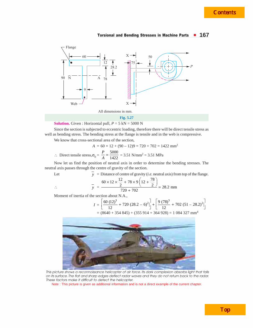
Torsional and Bending Stresses in Machine Parts 167
Fig. 5.27
Solution. Given : Horizontal pull, P = 5 kN = 5000 N
Since the section is subjected to eccentric loading, therefore there will be direct tensile stress aswell as bending stress. The bending stress at the flange is tensile and in the web is compressive.
We know that cross-sectional area of the section,
A = 60 × 12 + (90 – 12)9 = 720 + 702 = 1422 mm2
∴ Direct tensile stress,σ0 =5000
1422
P
A= = 3.51 N/mm2 = 3.51 MPa
Now let us find the position of neutral axis in order to determine the bending stresses. Theneutral axis passes through the centre of gravity of the section.
Let y = Distance of centre of gravity (i.e. neutral axis) from top of the flange.
∴ y =
12 7860 12 78 9 12
2 2 28.2 mm720 702
⎛ ⎞× × + × +⎜ ⎟⎝ ⎠ =
+Moment of inertia of the section about N.A.,
I =3 3
2 260 (12) 9 (78)720 (28.2 – 6) 702 (51 – 28.2)
12 12
⎡ ⎤ ⎡ ⎤+ + +⎢ ⎥ ⎢ ⎥⎣ ⎦ ⎣ ⎦
= (8640 + 354 845) + (355 914 + 364 928) = 1 084 327 mm4
This picture shows a reconnoissance helicopter of air force. Its dark complexion absorbs light that fallson its surface. The flat and sharp edges deflect radar waves and they do not return back to the radar.These factors make it difficult to detect the helicopter.
Note : This picture is given as additional information and is not a direct example of the current chapter.

168 A Textbook of Machine Design
Fig. 5.28
Distance of N.A. from the top of the flange,
yt = y = 28.2 mm
Distance of N.A. from the bottom of the web,
yc = 90 – 28.2 = 61.8 mm
Distance of N.A. from the point of application of the load (i.e. eccentricity of the load),
e = 50 + 28.2 = 78.2 mm
We know that bending moment exerted on the section,
M = P × e = 5000 × 78.2 = 391 × 103 N-mm
∴ Tensile stress in the flange,
σt =3
2. 391 10 28.210.17 N/mm
/ 1 084 327t
t t
M yM M
Z I y I
× ×= = = =
= 10.17 MPa
and compressive stress in the web,
σc =3
2. 391 10 61.822.28 N/mm
/ 1 084 327c
c c
M yM M
Z I y I
× ×= = = =
= 22.28 MPa
We know that maximum tensile stress in the flange,
σt(max) = σb + σo = σt + σo = 10.17 + 3.51 = 13.68 MPa Ans.and maximum compressive stress in the flange,
σc(max) = σb – σo = σc – σo = 22.28 – 3.51 = 18.77 MPa Ans.
Example 5.25. A mild steel bracket as shown in Fig. 5.28, is subjected to a pull of 6000 Nacting at 45° to its horizontal axis. The bracket has a rectangular section whose depth is twice thethickness. Find the cross-sectional dimensions of the bracket, if the permissible stress in the materialof the bracket is limited to 60 MPa.
Solution. Given : P = 6000 N ; θ = 45° ; σ = 60 MPa = 60 N/mm2
Let t = Thickness of the section in mm, and
b = Depth or width of the section = 2 t ...(Given)
We know that area of cross-section,
A = b × t = 2 t × t = 2 t2 mm2
and section modulus, Z =2
6
t b×
=2(2 )
6
t t
=3
34mm
6
t
Horizontal component of the load,
PH = 6000 cos 45°
= 6000 × 0.707
= 4242 N
∴ Bending moment due to horizontalcomponent of the load,
MH = PH × 75 = 4242 × 75 = 318 150 N-mm

Torsional and Bending Stresses in Machine Parts 169A little consideration will show that
the bending moment due to the horizontalcomponent of the load induces tensilestress on the upper surface of the bracketand compressive stress on the lowersurface of the bracket.
∴ Maximum bending stress onthe upper surface due to horizontalcomponent,
σbH = HM
Z
3
318 150 6
4
×=t
2
3
477 225N/mm (tensile)=
tVertical component of the load,
PV = 6000 sin 45° = 6000 × 0.707 = 4242 N∴ Direct stress due to vertical component,
σoV = 2V2 2
4242 2121N/mm
2
P
A t t= = (tensile)
Bending moment due to vertical component of the load,
MV = PV × 130 = 4242 × 130 = 551 460 N-mm
This bending moment induces tensile stress on the upper surface and compressive stress on thelower surface of the bracket.
∴ Maximum bending stress on the upper surface due to vertical component,
σbV = 2V3 3
551 460 6 827 190N/mm
4
M
Z t t
×= = (tensile)
and total tensile stress on the upper surface of the bracket,
σ = 3 2 3 3 2
477 225 2121 827 190 1 304 415 2121
t t t t t+ + = +
Since the permissible stress (σ) is 60 N/mm2, therefore
3 2
1 304 415 2121
t t+ = 60 or
3 2
21 740 35.41
t t+ =
∴ t = 28.4 mm Ans. ... (By hit and trial)
and b = 2 t = 2 × 28.4 = 56.8 mm Ans.Example 5.26. A C-clamp as shown in Fig. 5.29, carries a load P = 25 kN. The cross-section
of the clamp at X-X is rectangular having width equal to twice thickness. Assuming that the clamp ismade of steel casting with an allowable stress of 100 MPa, find its dimensions. Also determine thestresses at sections Y-Y and Z-Z.
Solution. Given : P = 25 kN = 25 × 103 N ; σt(max) = 100 MPa = 100 N/mm2
Dimensions at X-XLet t = Thickness of the section at X-X in mm, and
b = Width of the section at X-X in mm = 2 t ...(Given)
Schematic of a hydel turbine.Note : This picture is given as additional informationand is not a direct example of the current chapter.
Water
Curvedblades
Water
Generatorrotor
Turbine
shaft

170 A Textbook of Machine Design
We know that cross-sectional area at X-X,
A = b × t = 2 t × t = 2 t2 mm2
∴ Direct tensile stress at X-X,
σo =3
2
25 10
2
P
A t
×=
=3
23
12.5 10N/mm
t
×
Bending moment at X-X due to the load P,
M = P × e = 25 × 103 × 140
= 3.5 × 10⁶ N-mm
Section modulus, Z =2 2 3
3. (2 ) 4mm
6 6 6
t b t t t= =
...(Q b = 2t)
∴ Bending stress at X-X,
σb =6 6
23 3
3.5 10 6 5.25 10N/mm
4
M
Z t t
× × ×= = (tensile)
We know that the maximum tensile stress [σt (max)],
100 = σo + σb = 3 6
2 3
12.5 10 5.25 10
t t
× ×+
or 3
2 3
125 52.5 10– 1 0
t t
×+ =
∴ t = 38.5 mm Ans. ...(By hit and trial)
and b = 2 t = 2 × 38.5 = 77 mm Ans.Stresses at section Y-Y
Since the cross-section of frame is uniform throughout, therefore cross-sectional area of theframe at section Y-Y,
A = b sec 45° × t = 77 × 1.414 × 38.5 = 4192 mm2
Component of the load perpendicular to the section
= P cos 45° = 25 × 103 × 0.707 = 17 675 N
This component of the load produces uniform tensile stress over the section.
∴ Uniform tensile stress over the section,
σ = 17 675 / 4192 = 4.2 N/mm2 = 4.2 MPa
Component of the load parallel to the section
= P sin 45° = 25 × 103 × 0.707 = 17 675 N
This component of the load produces uniform shear stress over the section.
∴ Uniform shear stress over the section,
τ = 17 675 / 4192 = 4.2 N/mm2 = 4.2 MPa
Fig. 5.29

Torsional and Bending Stresses in Machine Parts 171We know that section modulus,
Z =2 2
3 3( sec 45 ) 38.5 (77 1.414)76 10 mm
6 6
t b ° ×= = ×
Bending moment due to load (P) over the section Y-Y,
M = 25 × 103 × 140 = 3.5 × 10⁶ N-mm
∴ Bending stress over the section,
σb =6
3
3.5 10
76 10
M
Z
×=×
= 46 N/mm2 = 46 MPa
Due to bending, maximum tensile stress at the inner corner and the maximum compressive stressat the outer corner is produced.
∴ Maximum tensile stress at the inner corner,
σt = σb + σo = 46 + 4.2 = 50.2 MPa
and maximum compressive stress at the outer corner,
σc = σb – σo = 46 – 4.2 = 41.8 MPa
Since the shear stress acts at right angles to the tensile and compressive stresses, thereforemaximum principal stress (tensile) on the section Y-Y at the inner corner
=2 2 2 21 50.2 1
( ) 4 (50.2) 4 (4.2) MPa2 2 2 2
tt
σ ⎡ ⎤ ⎡ ⎤+ σ + τ = + + ×⎣ ⎦⎣ ⎦
= 25.1 + 25.4 = 50.5 MPa Ans.
and maximum principal stress (compressive) on section Y-Y at outer corner
=2 2 2 21 41.8 1
( ) 4 (41.8) 4 (4.2) MPa2 2 2 2c
cσ ⎡ ⎤ ⎡ ⎤+ σ + τ = + + ×⎣ ⎦⎣ ⎦
= 20.9 + 21.3 = 42.2 MPa Ans.
Maximum shear stress = 2 2 2 21 12 2
( ) 4 (50.2) 4 (4.2) 25.4 MPat⎡ ⎤ ⎡ ⎤σ + τ = + × =⎣ ⎦⎣ ⎦ Ans.
Stresses at section Z-Z
We know that bending moment at section Z-Z,
= 25 × 103 × 40 = 1 × 10⁶ N-mm
and section modulus, Z =2 2. 38.5 (77)
6 6
t b = = 38 × 103 mm3
∴ Bending stress at section Z-Z,
σb =6
3
1 10
38 10
M
Z
×=×
= 26.3 N/mm2 = 26.3 MPa Ans.
The bending stress is tensile at the inner edge and compressive at the outer edge. The magnitudeof both these stresses is 26.3 MPa. At the neutral axis, there is only transverse shear stress. The shearstress at the inner and outer edges will be zero.
We know that *maximum transverse shear stress,
τmax = 1.5 × Average shear stress = 325 10
1.5 1.5. 77 38.5
P
b t
×× = ××
= 12.65 N/mm2 = 12.65 MPa Ans.
* Refer Art. 5.16

172 A Textbook of Machine Design
5.16 Shear Stresses in BeamsIn the previous article, we have assumed that no shear force is acting on the section. But, in
actual practice, when a beam is loaded, the shear force at a section always comes into play along withthe bending moment. It has been observed that the effect of the shear stress, as compared to thebending stress, is quite negligible and is of not much importance. But, sometimes, the shear stress ata section is of much importance in the design. It may be noted that the shear stress in a beam is notuniformly distributed over the cross-section but varies from zero at the outer fibres to a maximum atthe neutral surface as shown in Fig. 5.30 and Fig. 5.31.
Fig. 5.30. Shear stress in a rectangular beam. Fig. 5.31. Shear stress in a circular beam.
The shear stress at any section acts in a plane at right angle to the plane of the bending stress andits value is given by
τ = ..
FA y
I b×
Note : This picture is given as additional information and is not a direct example of the current chapter.
General layout of a hydroelectric plant.
Sluice gate Dam
Water from thereservoirpasses througha gate
The flow ofwater makesthe turbine shaftturn
Turbines drivegenerator toproduceelectricity
Cables carryaway theelectricity foruse
Excess waterflows overspillway
River
Spillway

Torsional and Bending Stresses in Machine Parts 173where F = Vertical shear force acting on the section,
I = Moment of inertia of the section about the neutral axis,
b = Width of the section under consideration,
A = Area of the beam above neutral axis, and
y = Distance between the C.G. of the area and the neutral axis.
The following values of maximum shear stress for different cross-section of beams may be noted:
1. For a beam of rectangular section, as shown in Fig. 5.30, the shear stress at a distance y fromneutral axis is given by
τ =2
23
3–
2 4 2 .
F h Fy
I b h
⎛ ⎞=⎜ ⎟
⎝ ⎠ (h2 – 4y2) ...
3.
12
⎡ ⎤=⎢ ⎥
⎣ ⎦Q
b hI
and maximum shear stress,
τmax =3
2 .
F
b h... Substituting
2⎛ ⎞=⎜ ⎟⎝ ⎠
hy
= 1.5 τ(average) ... ( ) Area .⎡ ⎤τ = =⎢ ⎥⎣ ⎦Q average
F F
b h
The distribution of stress is shown in Fig. 5.30.
2. For a beam of circular section as shown in Fig. 5.31, the shear stress at a distance y fromneutral axis is given by
τ =2
2 2 24
16– ( – 4 )
3 4 3
F d Fy d y
I d
⎛ ⎞=⎜ ⎟
⎝ ⎠ πand the maximum shear stress,
τmax =2
4
34
F
dπ×
... Substituting2
⎛ ⎞=⎜ ⎟⎝ ⎠
dy
= ( )4
3 averageτ ... ( )2Area
4
⎡ ⎤τ = =⎢ ⎥π⎢ ⎥⎣ ⎦
Q averageF F
d
The distribution of stress is shown in Fig. 5.31.
3. For a beam of I-section as shown in Fig. 5.32, the maximum shear stress occurs at the neutralaxis and is given by
τmax =2
2 2 .( – )
. 8 8
F B b hH h
I b
⎡ ⎤+⎢ ⎥
⎣ ⎦
Fig. 5.32

174 A Textbook of Machine Design
Shear stress at the joint of the web and the flange
=8
F
I (H2 – h2)
and shear stress at the junction of the top of the web and bottom of the flange
=8
F B
I b× (H2 – h2)
The distribution of stress is shown in Fig. 5.32.
Example 5.27. A beam of I-section 500 mm deep and 200 mm wide has flanges 25 mmthick and web 15 mm thick, as shown in Fig. 5.33 (a). It carries a shearing force of 400 kN. Findthe maximum intensity of shear stress in the section, assuming the moment of inertia to be645 × 106 mm4. Also find the shear stress at the joint and at the junction of the top of the weband bottom of the flange.
Solution. Given : H = 500 mm ; B = 200 mm ; h = 500 – 2 × 25 = 450 mm ; b = 15 mm ;F = 400 kN = 400 × 103 N ; I = 645 × 106 mm4
Fig. 5.33
Maximum intensity of shear stressWe know that maximum intensity of shear stress,
τmax =2
2 2 .( – )
. 8 8
F B b hH h
I b
⎡ ⎤+⎢ ⎥
⎣ ⎦
=3 2
2 2 26
400 10 200 15 450(500 – 450 ) N/mm
8 8645 10 15
⎡ ⎤× ×+⎢ ⎥⎣ ⎦× ×
= 64.8 N/mm2 = 64.8 MPa Ans.
The maximum intensity of shear stress occurs at neutral axis.
Note :The maximum shear stress may also be obtained by using the following relation :
τmax =. .
.
F A y
I b
We know that area of the section above neutral axis,
A = 200 × 25 + 450
2 × 15 = 8375 mm2
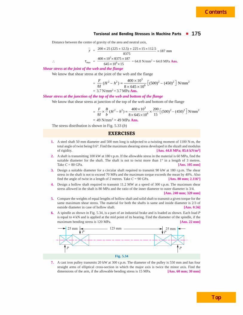
Torsional and Bending Stresses in Machine Parts 175Distance between the centre of gravity of the area and neutral axis,
y = 200 25 (225 12.5) 225 15 112.5187 mm
8375
× + + × × =
∴ maxτ =3
6
400 10 8375 187
645 10 15
× × ×× ×
= 64.8 N/mm2 = 64.8 MPa Ans.
Shear stress at the joint of the web and the flangeWe know that shear stress at the joint of the web and the flange
=3
2 2 2 2 26
400 10( – ) (500) – (450) N/mm
8 8 645 10
FH h
I
× ⎡ ⎤= ⎣ ⎦× ×= 3.7 N/mm2 = 3.7 MPa Ans.
Shear stress at the junction of the top of the web and bottom of the flangeWe know that shear stress at junction of the top of the web and bottom of the flange
=3
2 2 2 2 26
400 10 200( – ) (500) – (450) N/mm
8 158 645 10
F BH h
I b
× ⎡ ⎤× = × ⎣ ⎦× ×= 49 N/mm2 = 49 MPa Ans.
The stress distribution is shown in Fig. 5.33 (b)
EEEEEXEXEXEXEXERRRRRCISECISECISECISECISESSSSS
1. A steel shaft 50 mm diameter and 500 mm long is subjected to a twisting moment of 1100 N-m, thetotal angle of twist being 0.6°. Find the maximum shearing stress developed in the shzaft and modulusof rigidity. [Ans. 44.8 MPa; 85.6 kN/m2]
2. A shaft is transmitting 100 kW at 180 r.p.m. If the allowable stress in the material is 60 MPa, find thesuitable diameter for the shaft. The shaft is not to twist more than 1° in a length of 3 metres.Take C = 80 GPa. [Ans. 105 mm]
3. Design a suitable diameter for a circular shaft required to transmit 90 kW at 180 r.p.m. The shearstress in the shaft is not to exceed 70 MPa and the maximum torque exceeds the mean by 40%. Alsofind the angle of twist in a length of 2 metres. Take C = 90 GPa. [Ans. 80 mm; 2.116°]
4. Design a hollow shaft required to transmit 11.2 MW at a speed of 300 r.p.m. The maximum shearstress allowed in the shaft is 80 MPa and the ratio of the inner diameter to outer diameter is 3/4.
[Ans. 240 mm; 320 mm]
5. Compare the weights of equal lengths of hollow shaft and solid shaft to transmit a given torque for thesame maximum shear stress. The material for both the shafts is same and inside diameter is 2/3 ofoutside diameter in case of hollow shaft. [Ans. 0.56]
6. A spindle as shown in Fig. 5.34, is a part of an industrial brake and is loaded as shown. Each load Pis equal to 4 kN and is applied at the mid point of its bearing. Find the diameter of the spindle, if themaximum bending stress is 120 MPa. [Ans. 22 mm]
Fig. 5.34
7. A cast iron pulley transmits 20 kW at 300 r.p.m. The diameter of the pulley is 550 mm and has fourstraight arms of elliptical cross-section in which the major axis is twice the minor axis. Find thedimensions of the arm, if the allowable bending stress is 15 MPa. [Ans. 60 mm; 30 mm]

176 A Textbook of Machine Design
8. A shaft is supported in bearings, the distance between their centres being 1 metre. It carries a pulley inthe centre and it weighs 1 kN. Find the diameter of the shaft, if the permissible bending stress for theshaft material is 40 MPa. [Ans. 40 mm]
9. A punch press, used for stamping sheet metal, has a punching capacity of 50 kN. The section of theframe is as shown in Fig. 5.35. Find the resultant stress at the inner and outer fibre of the section.
[Ans. 28.3 MPa (tensile); 17.7 MPa (compressive)]
Fig. 5.35 Fig. 5.36
10. A crane hook has a trapezoidal section at A-A as shown in Fig. 5.36. Find the maximum stress atpoints P and Q. [Ans. 118 MPa (tensile); 62 MPa (compressive)]
11. A rotating shaft of 16 mm diameter is made of plain carbon steel. It is subjected to axial load of 5000N, a steady torque of 50 N-m and maximum bending moment of 75 N-m. Calculate the factor of safetyavailable based on 1. Maximum normal stress theory; and 2. Maximum shear stress theory.Assume yield strength as 400 MPa for plain carbon steel. If all other data remaining same, whatmaximum yield strength of shaft material would be necessary using factor of safety of 1.686 andmaximum distortion energy theory of failure. Comment on the result you get.
[Ans. 1.752; 400 MPa]12. A hand cranking lever, as shown in Fig. 5.37, is used to start a truck engine by applying a force
F = 400 N. The material of the cranking lever is 30C8 for which yield strength = 320 MPa; Ultimatetensile strength = 500 MPa ; Young’s modulus = 205 GPa ; Modulus of rigidity = 84 GPa and poisson’sratio = 0.3.
Fig. 5.37
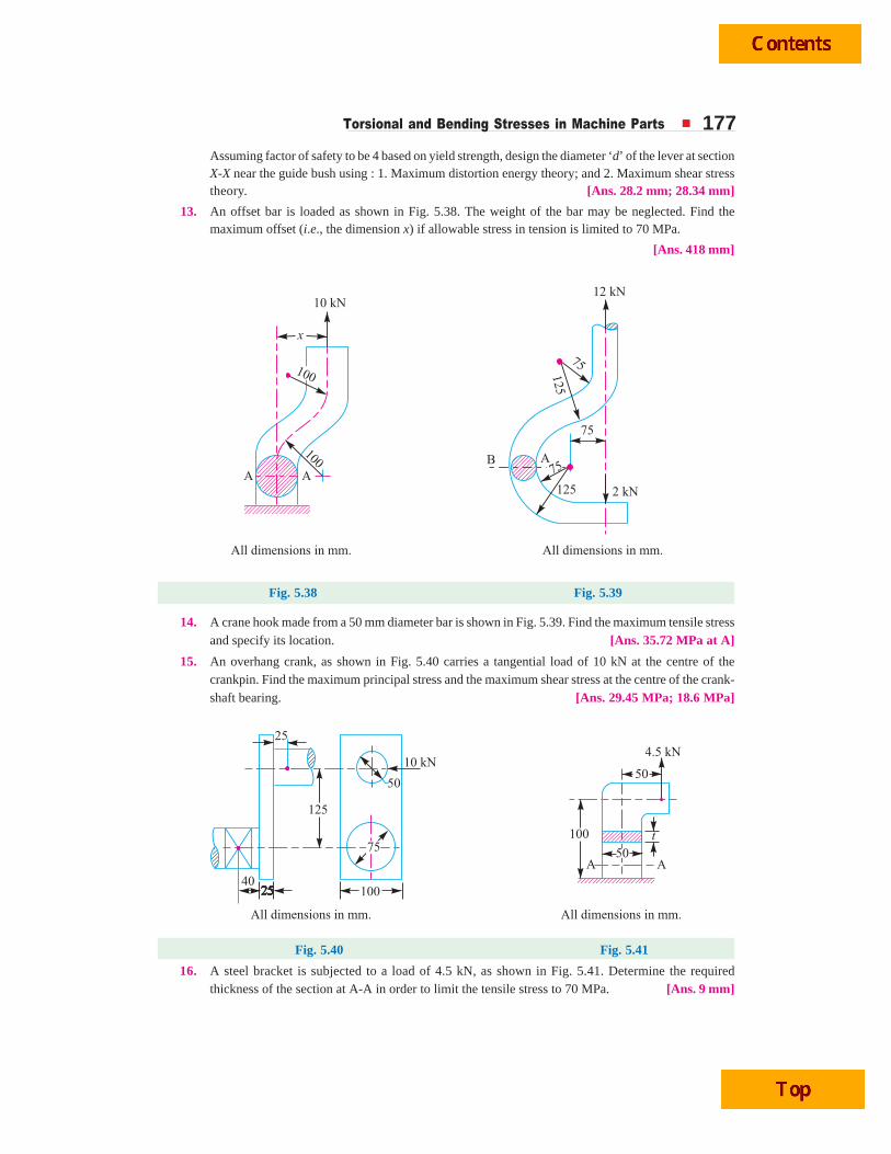
Torsional and Bending Stresses in Machine Parts 177Assuming factor of safety to be 4 based on yield strength, design the diameter ‘d’ of the lever at sectionX-X near the guide bush using : 1. Maximum distortion energy theory; and 2. Maximum shear stresstheory. [Ans. 28.2 mm; 28.34 mm]
13. An offset bar is loaded as shown in Fig. 5.38. The weight of the bar may be neglected. Find themaximum offset (i.e., the dimension x) if allowable stress in tension is limited to 70 MPa.
[Ans. 418 mm]
Fig. 5.38 Fig. 5.39
14. A crane hook made from a 50 mm diameter bar is shown in Fig. 5.39. Find the maximum tensile stressand specify its location. [Ans. 35.72 MPa at A]
15. An overhang crank, as shown in Fig. 5.40 carries a tangential load of 10 kN at the centre of thecrankpin. Find the maximum principal stress and the maximum shear stress at the centre of the crank-shaft bearing. [Ans. 29.45 MPa; 18.6 MPa]
Fig. 5.40 Fig. 5.41
16. A steel bracket is subjected to a load of 4.5 kN, as shown in Fig. 5.41. Determine the requiredthickness of the section at A-A in order to limit the tensile stress to 70 MPa. [Ans. 9 mm]

178 A Textbook of Machine Design
17. A wall bracket, as shown in Fig. 5.42, is subjected to a pull of P = 5 kN, at 60° to the vertical. Thecross-section of bracket is rectangular having b = 3t . Determine the dimensions b and t if the stressin the material of the bracket is limited to 28 MPa. [Ans. 75 mm; 25 mm]
Fig. 5.42 Fig. 5.43
18. A bracket, as shown in Fig. 5.43, is bolted to the framework of a machine which carries a load P. Thecross-section at 40 mm from the fixed end is rectangular with dimensions, 60 mm × 30 mm. If themaximum stress is limited to 70 MPa, find the value of P.
[Ans. 3000 N]
19. A T-section of a beam, as shown in Fig. 5.44, is subjected to a vertical shear force of 100 kN. Calcu-late the shear stress at the neutral axis and at the junction of the web and theflange. The moment of inertia at the neutral axis is 113.4 × 106 mm4.
[Ans. 11.64 MPa; 11 MPa; 2.76 MPa]
Fig. 5.44 Fig. 5.45
20. A beam of channel section, as shown in Fig. 5.45, is subjected to a vertical shear force of 50 kN. Findthe ratio of maximum and mean shear stresses. Also draw the distribution of shear stresses.
[Ans. 2.22]
QQQQQUEUEUEUEUESTSTSTSTSTIONSIONSIONSIONSIONS
1. Derive a relation for the shear stress developed in a shaft, when it is subjected to torsion.
2. State the assumptions made in deriving a bending formula.

Torsional and Bending Stresses in Machine Parts 1793. Prove the relation: M/I = σ/y = E/R
where M = Bending moment; I = Moment of inertia; σ = Bending stress in a fibre at a distance y fromthe neutral axis; E = Young’s modulus; and R = Radius of curvature.
4. Write the relations used for maximum stress when a machine member is subjected to tensile or com-pressive stresses along with shearing stresses.
5. Write short note on maximum shear stress theory verses maximum strain energy theory.
6. Distinguish clearly between direct stress and bending stress.
7. What is meant by eccentric loading and eccentricity?
8. Obtain a relation for the maximum and minimum stresses at the base of a symmetrical column,when it is subjected to
(a) an eccentric load about one axis, and (b) an eccentric load about two axes.
OBJECTOBJECTOBJECTOBJECTOBJECTIVE IVE IVE IVE IVE TTTTTYPYPYPYPYPE QE QE QE QE QUEUEUEUEUESTSTSTSTSTIONSIONSIONSIONSIONS
1. When a machine member is subjected to torsion, the torsional shear stress set up in the member is
(a) zero at both the centroidal axis and outer surface of the member
(b) Maximum at both the centroidal axis and outer surface of the member
(c) zero at the centroidal axis and maximum at the outer surface of the member
(d) none of the above
2. The torsional shear stress on any cross-section normal to the axis is ......... the distance from the centreof the axis.
(a) directly proportional to (b) inversely proportional to
3. The neutral axis of a beam is subjected to
(a) zero stress (b) maximum tensile stress
(c) maximum compressive stress (d) maximum shear stress
4. At the neutral axis of a beam,
(a) the layers are subjected to maximum bending stress
(b) the layers are subjected to tension (c) the layers are subjected to compression
(d) the layers do not undergo any strain
5. The bending stress in a curved beam is
(a) zero at the centroidal axis (b) zero at the point other than centroidal axis
(c) maximum at the neutral axis (d) none of the above
6. The maximum bending stress, in a curved beam having symmetrical section, always occur, at the
(a) centroidal axis (b) neutral axis
(c) inside fibre (d) outside fibre
7. If d = diameter of solid shaft and τ = permissible stress in shear for the shaft material, then torsionalstrength of shaft is written as
(a)4
32
π τd (b) d loge τ
(c)3
16
π τd (d)3
32
π τd
8. If di and do are the inner and outer diameters of a hollow shaft, then its polar moment of inertia is
(a)4 4( ) – ( )
32
π ⎡ ⎤⎣ ⎦o id d (b)3 3( ) – ( )
32
π ⎡ ⎤⎣ ⎦o id d
(c)2 2( ) – ( )
32
π ⎡ ⎤⎣ ⎦o id d (d) ( – )32
πo id d

180 A Textbook of Machine Design
9. Two shafts under pure torsion are of identical length and identical weight and are made of samematerial. The shaft A is solid and the shaft B is hollow. We can say that
(a) shaft B is better than shaft A
(b) shaft A is better than shaft B
(c) both the shafts are equally good
10. A solid shaft transmits a torque T. The allowable shear stress is τ. The diameter of the shaft is
(a) 316
π τT
(b) 332
π τT
(c) 364
π τT
(d) 316
τT
11. When a machine member is subjected to a tensile stress (σt) due to direct load or bending and a shearstress (τ) due to torsion, then the maximum shear stress induced in the member will be
(a) 2 212
( ) 4⎡ ⎤σ + τ⎣ ⎦t (b) 2 212
( ) – 4⎡ ⎤σ τ⎣ ⎦t
(c) 2 2( ) 4⎡ ⎤σ + τ⎣ ⎦t (d) (σt)2 + 4 τ2
12. Rankine’s theory is used for
(a) brittle materials (b) ductile materials
(c) elastic materials (d) plastic materials
13. Guest’s theory is used for
(a) brittle materials (b) ductile materials
(c) elastic materials (d) plastic materials
14. At the neutral axis of a beam, the shear stress is
(a) zero (b) maximum
(c) minimum
15. The maximum shear stress developed in a beam of rectangular section is ........ the average shearstress.
(a) equal to (b) 43 times
(c) 1.5 times
ANSWEANSWEANSWEANSWEANSWERRRRRSSSSS
1. (b) 2. (a) 3. (a) 4. (d) 5. (b)
6. (c) 7. (c) 8. (a) 9. (a) 10. (a)
11. (a) 12. (a) 13. (b) 14. (b) 15. (c)

Variable Stresses in Machine Parts 181
Variable Stresses inMachine Parts
181
1. Introduction.2. Completely Reversed or
Cyclic Stresses.3. Fatigue and Endurance
Limit.4. Effect of Loading on
Endurance Limit—LoadFactor.
5. Effect of Surface Finish onEndurance Limit—SurfaceFinish Factor.
6. Effect of Size on EnduranceLimit—Size Factor.
8. Relation BetweenEndurance Limit andUltimate Tensile Strength.
9. Factor of Safety for FatigueLoading.
10. Stress Concentration.11. Theoretical or Form Stress
Concentration Factor.12. Stress Concentration due to
Holes and Notches.14. Factors to be Considered
while Designing MachineParts to Avoid FatigueFailure.
15. Stress ConcentrationFactor for Various MachineMembers.
16. Fatigue StressConcentration Factor.
17. Notch Sensitivity.18. Combined Steady and
Variable Stresses.19. Gerber Method for
Combination of Stresses.20. Goodman Method for
Combination of Stresses.21. Soderberg Method for
Combination of Stresses.
6CHAPTER
6.1 IntroductionWe have discussed, in the previous chapter, the
stresses due to static loading only. But only a few machineparts are subjected to static loading. Since many of themachine parts (such as axles, shafts, crankshafts, connectingrods, springs, pinion teeth etc.) are subjected to variable oralternating loads (also known as fluctuating or fatigueloads), therefore we shall discuss, in this chapter, thevariable or alternating stresses.
6.2 Completely Reversed or Cyclic StressesConsider a rotating beam of circular cross-section
and carrying a load W, as shown in Fig. 6.1. This loadinduces stresses in the beam which are cyclic in nature. Alittle consideration will show that the upper fibres of thebeam (i.e. at point A) are under compressive stress and thelower fibres (i.e. at point B) are under tensile stress. After

182 A Textbook of Machine Design
half a revolution, the point B occupies the position ofpoint A and the point A occupies the position of point B.Thus the point B is now under compressive stress andthe point A under tensile stress. The speed of variationof these stresses depends upon the speed of the beam.
From above we see that for each revolution of thebeam, the stresses are reversed from compressive to tensile.The stresses which vary from one value of compressive tothe same value of tensile or vice versa, are known as completely reversed or cyclic stresses.Notes: 1. The stresses which vary from a minimum value to a maximum value of the same nature, (i.e. tensile orcompressive) are called fluctuating stresses.
2. The stresses which vary from zero to a certain maximum value are called repeated stresses.
3. The stresses which vary from a minimum value to a maximum value of the opposite nature (i.e. from acertain minimum compressive to a certain maximum tensile or from a minimum tensile to a maximum compressive)are called alternating stresses.
6.3 Fatigue and Endurance LimitIt has been found experimentally that when a material is subjected to repeated stresses, it fails at
stresses below the yield point stresses. Such type of failure of a material is known as fatigue. Thefailure is caused by means of a progressive crack formation which are usually fine and of microscopicsize. The failure may occur even without any prior indication. The fatigue of material is effected bythe size of the component, relative magnitude of static and fluctuating loads and the number of loadreversals.
Fig. 6.2. Time-stress diagrams.
In order to study the effect of fatigue of a material, a rotating mirror beam method is used. Inthis method, a standard mirror polished specimen, as shown in Fig. 6.2 (a), is rotated in a fatigue
Fig. 6.1. Reversed or cyclic stresses.

Variable Stresses in Machine Parts 183testing machine while the specimen is loadedin bending. As the specimen rotates, thebending stress at the upper fibres varies frommaximum compressive to maximum tensilewhile the bending stress at the lower fibresvaries from maximum tensile to maximumcompressive. In other words, the specimen issubjected to a completely reversed stress cycle.This is represented by a time-stress diagramas shown in Fig. 6.2 (b). A record is kept ofthe number of cycles required to producefailure at a given stress, and the results areplotted in stress-cycle curve as shown in Fig.6.2 (c). A little consideration will show that ifthe stress is kept below a certain value as shownby dotted line in Fig. 6.2 (c), the material will not fail whatever may be the number of cycles. Thisstress, as represented by dotted line, is known as endurance or fatigue limit (σe). It is defined asmaximum value of the completely reversed bending stress which a polished standard specimen canwithstand without failure, for infinite number of cycles (usually 107 cycles).
It may be noted that the term endurance limit is used for reversed bending only while for othertypes of loading, the term endurance strength may be used when referring the fatigue strength of thematerial. It may be defined as the safe maximum stress which can be applied to the machine partworking under actual conditions.
We have seen that when a machine member is subjected to a completely reversed stress, themaximum stress in tension is equal to the maximum stress in compression as shown in Fig. 6.2 (b). Inactual practice, many machine members undergo different range of stress than the completelyreversed stress.
The stress verses time diagram for fluctuating stress having values σmin and σmax is shown inFig. 6.2 (e). The variable stress, in general, may be considered as a combination of steady (or mean oraverage) stress and a completely reversed stress component σv. The following relations are derivedfrom Fig. 6.2 (e):
1. Mean or average stress,
σm =2
max minσ + σ
2. Reversed stress component or alternating or variable stress,
σv =2
max minσ − σ
Note: For repeated loading, the stress varies from maximum to zero (i.e. σmin = 0) in each cycle as shown in Fig.6.2 (d).
∴ σm = σv = 2
σmax
3. Stress ratio, R = max
min
σσ . For completely reversed stresses, R = – 1 and for repeated stresses,
R = 0. It may be noted that R cannot be greater than unity.
4. The following relation between endurance limit and stress ratio may be used
σ'e =3
2e
R
σ−
A machine part is being turned on a Lathe.

184 A Textbook of Machine Design
where σ'e = Endurance limit for any stress range represented by R.
σe = Endurance limit for completely reversed stresses, and
R = Stress ratio.
6.4 Effect of Loading on Endurance Limit—Load FactorThe endurance limit (σe) of a material as determined by the rotating beam method is for
reversed bending load. There are many machine members which are subjected to loads other thanreversed bending loads. Thus the endurance limit willalso be different for different types of loading. Theendurance limit depending upon the type of loading maybe modified as discussed below:
Let Kb = Load correction factor for thereversed or rotating bending load.Its value is usually taken as unity.
Ka = Load correction factor for thereversed axial load. Its value maybe taken as 0.8.
Ks = Load correction factor for thereversed torsional or shear load. Itsvalue may be taken as 0.55 forductile materials and 0.8 for brittlematerials.
∴ Endurance limit for reversed bending load, σeb = σe.Kb = σe ...( QKb = 1)
Endurance limit for reversed axial load, σea = σe.Ka
and endurance limit for reversed torsional or shear load, τe = σe.Ks
6.5 Effect of Surface Finish on Endurance Limit—Surface Finish FactorWhen a machine member is subjected to variable loads, the endurance limit of the material for
that member depends upon the surface conditions. Fig. 6.3 shows the values of surface finish factorfor the various surface conditions and ultimate tensile strength.
Fig. 6.3. Surface finish factor for various surface conditions.
When the surface finish factor is known, then the endurance limit for the material of the machinemember may be obtained by multiplying the endurance limit and the surface finish factor. We see that
Shaft drive.

Variable Stresses in Machine Parts 185for a mirror polished material, the surface finish factor is unity. In other words, the endurance limit formirror polished material is maximum and it goes on reducing due to surface condition.
Let Ksur = Surface finish factor.
∴ Endurance limit,
σe1 = σeb.Ksur = σe.Kb.Ksur = σe.Ksur ...( Q Kb = 1)
...(For reversed bending load)
= σea.Ksur = σe.Ka.Ksur ...(For reversed axial load)
= τe.Ksur = σe.Ks.Ksur ...(For reversed torsional or shear load)
Note : The surface finish factor for non-ferrous metals may be taken as unity.
6.6 Effect of Size on Endurance Limit—Size FactorA little consideration will show that if the size of the standard specimen as shown in Fig. 6.2 (a)
is increased, then the endurance limit of the material will decrease. This is due to the fact that a longerspecimen will have more defects than a smaller one.
Let Ksz = Size factor.
∴ Endurance limit,
σe2 = σe1 × Ksz ...(Considering surface finish factor also)
= σeb.Ksur.Ksz = σe.Kb.Ksur.Ksz = σe.Ksur.Ksz ( Q Kb = 1)
= σea.Ksur.Ksz = σe.Ka.Ksur.Ksz ...(For reversed axial load)
= τe.Ksur.Ksz = σe.Ks.Ksur.Ksz ... (For reversed torsional or shear load)
Notes: 1. The value of size factor is taken as unity for the standard specimen having nominal diameter of7.657 mm.
2. When the nominal diameter of the specimen is more than 7.657 mm but less than 50 mm, the value ofsize factor may be taken as 0.85.
3. When the nominal diameter of the specimen is more than 50 mm, then the value of size factor may betaken as 0.75.
6.7 Effect of Miscellaneous Factors onEndurance Limit
In addition to the surface finish factor (Ksur),size factor (Ksz) and load factors Kb, Ka and Ks, thereare many other factors such as reliability factor (Kr),temperature factor (Kt), impact factor (Ki) etc. whichhas effect on the endurance limit of a material. Con-sidering all these factors, the endurance limit may bedetermined by using the following expressions :
1. For the reversed bending load, endurancelimit,
σ'e = σeb.Ksur.Ksz.Kr.Kt.Ki
2. For the reversed axial load, endurance limit,σ'e = σea.Ksur.Ksz.Kr.Kt.Ki
3. For the reversed torsional or shear load,endurance limit,
σ'e = τe.Ksur.Ksz.Kr.Kt.Ki
In solving problems, if the value of any of theabove factors is not known, it may be taken as unity.
In addition to shear, tensile, compressive andtorsional stresses, temperature can add its own
stress (Ref. Chapter 4)Note : This picture is given as additional informationand is not a direct example of the current chapter.

186 A Textbook of Machine Design
6.8 Relation Between Endurance Limit and Ultimate Tensile StrengthIt has been found experimentally that endurance limit (σe) of a material subjected to fatigue
loading is a function of ultimate tensile strength (σu). Fig. 6.4 shows the endurance limit of steelcorresponding to ultimate tensile strength for different surface conditions. Following are someempirical relations commonly used in practice :
Fig. 6.4. Endurance limit of steel corresponding to ultimate tensile strength.
For steel, σe = 0.5 σu ;
For cast steel, σe = 0.4 σu ;
For cast iron, σe = 0.35 σu ;
For non-ferrous metals and alloys, σe = 0.3 σu
6.9 Factor of Safety for Fatigue LoadingWhen a component is subjected to fatigue loading, the endurance limit is the criterion for faliure.
Therefore, the factor of safety should be based on endurance limit. Mathematically,
Factor of safety (F.S.) =Endurance limit stress
Design or working stresse
d
σ=
σNote: For steel, σe = 0.8 to 0.9 σy
where σe = Endurance limit stress for completely reversed stress cycle, and
σy = Yield point stress.
Example 6.1. Determine the design stress for a piston rod where the load is completelyreversed. The surface of the rod is ground andthe surface finish factor is 0.9. There is no stressconcentration. The load is predictable and thefactor of safety is 2.
Solution. Given : Ksur = 0.9 ; F.S. = 2
The piston rod is subjected to reversedaxial loading. We know that for reversed axialloading, the load correction factor (Ka) is 0.8.
Piston rod

Variable Stresses in Machine Parts 187
Fig. 6.5. Stress concentration.
If σe is the endurance limit for reversed bending load, then endurance limit for reversed axialload,
σea = σe × Ka × Ksur = σe × 0.8 × 0.9 = 0.72 σe
We know that design stress,
σd = 0.72
0.36. . 2ea e
eF S
σ σ= = σ Ans.
6.10 Stress ConcentrationWhenever a machine component changes the shape of its cross-section, the simple stress
distribution no longer holds good and the neighbourhood of the discontinuity is different. Thisirregularity in the stress distribution caused by abrupt changes of form is called stress concentration.It occurs for all kinds of stresses in the presence of fillets, notches, holes, keyways, splines, surfaceroughness or scratches etc.
In order to understand fully the idea of stressconcentration, consider a member with differentcross-section under a tensile load as shown in Fig. 6.5. A little consideration will show that thenominal stress in the right and left hand sides willbe uniform but in the region where the cross-section is changing, a re-distribution of the forcewithin the member must take place. The materialnear the edges is stressed considerably higher than the average value. The maximum stress occurs atsome point on the fillet and is directed parallel to the boundary at that point.
6.11 Theoretical or Form Stress Concentration FactorThe theoretical or form stress concentration factor is defined as the ratio of the maximum stress
in a member (at a notch or a fillet) to the nominal stress at the same section based upon net area.Mathematically, theoretical or form stress concentration factor,
Kt = Maximum stress
Nominal stressThe value of Kt depends upon the material and geometry of the part.
Notes: 1. In static loading, stress concentration in ductile materials is not so serious as in brittle materials,because in ductile materials local deformation or yielding takes place which reduces the concentration. In brittlematerials, cracks may appear at these local concentrations of stress which will increase the stress over the rest ofthe section. It is, therefore, necessary that in designing parts of brittle materials such as castings, care should betaken. In order to avoid failure due to stress concentration, fillets at the changes of section must be provided.
2. In cyclic loading, stress concentration in ductile materials is always serious because the ductility of thematerial is not effective in relieving the concentration of stress caused by cracks, flaws, surface roughness, orany sharp discontinuity in the geometrical form of the member. If the stress at any point in a member is above theendurance limit of the material, a crack may develop under the action of repeated load and the crack will lead tofailure of the member.
6.12 Stress Concentration due to Holes and NotchesConsider a plate with transverse elliptical hole and subjected to a tensile load as shown in Fig.
6.6 (a). We see from the stress-distribution that the stress at the point away from the hole is practicallyuniform and the maximum stress will be induced at the edge of the hole. The maximum stress is givenby
σmax =2
1⎛ ⎞σ +⎜ ⎟⎝ ⎠
a
b

188 A Textbook of Machine Design
and the theoretical stress concentration factor,
Kt = 2
1max a
b
σ ⎛ ⎞= +⎜ ⎟⎝ ⎠σWhen a/b is large, the ellipse approaches a crack transverse to the load and the value of Kt
becomes very large. When a/b is small, the ellipse approaches a longitudinal slit [as shown in Fig. 6.6(b)] and the increase in stress is small. When the hole is circular as shown in Fig. 6.6 (c), then a/b = 1and the maximum stress is three times the nominal value.
Fig. 6.6. Stress concentration due to holes.
The stress concentration in the notched tension member, asshown in Fig. 6.7, is influenced by the depth a of the notch and radiusr at the bottom of the notch. The maximum stress, which applies tomembers having notches that are small in comparison with the widthof the plate, may be obtained by the following equation,
σmax =2
1⎛ ⎞σ +⎜ ⎟⎝ ⎠
a
r
6.13 Methods of Reducing Stress ConcentrationWe have already discussed in Art 6.10 that whenever there is a
change in cross-section, such as shoulders, holes, notches or keyways and where there is an interfer-ence fit between a hub or bearing race and a shaft, then stress concentration results. The presence of
stress concentration can not be totally eliminated but it may be reduced to some extent. A device orconcept that is useful in assisting a design engineer to visualize the presence of stress concentration
Fig. 6.7. Stress concentrationdue to notches.
Crankshaft

Variable Stresses in Machine Parts 189and how it may be mitigated is that of stress flow lines, as shown in Fig. 6.8. The mitigation of stressconcentration means that the stress flow lines shall maintain their spacing as far as possible.
Fig. 6.8
In Fig. 6.8 (a) we see that stress lines tend to bunch up and cut very close to the sharp re-entrantcorner. In order to improve the situation, fillets may be provided, as shown in Fig. 6.8 (b) and (c) togive more equally spaced flow lines.
Figs. 6.9 to 6.11 show the several ways of reducing the stress concentration in shafts and othercylindrical members with shoulders, holes and threads respectively. It may be noted that it is notpracticable to use large radius fillets as in case of ball and roller bearing mountings. In such cases,notches may be cut as shown in Fig. 6.8 (d) and Fig. 6.9 (b) and (c).
Fig. 6.9. Methods of reducing stress concentration in cylindrical members with shoulders.
Fig. 6.10. Methods of reducing stress concentration in cylindrical members with holes.
Fig. 6.11. Methods of reducing stress concentration in cylindrical members with holes.
The stress concentration effects of a press fit may be reduced by making more gradual transitionfrom the rigid to the more flexible shaft. The various ways of reducing stress concentration for suchcases are shown in Fig. 6.12 (a), (b) and (c).

190 A Textbook of Machine Design
6.14 Factors to be Considered while Designing Machine Parts to AvoidFatigue Failure
The following factors should be considered while designing machine parts to avoid fatigue failure:1. The variation in the size of the component should be as gradual as possible.2. The holes, notches and other stress raisers should be avoided.3. The proper stress de-concentrators such as fillets and notches should be provided
wherever necessary.
Fig. 6.12. Methods of reducing stress concentration of a press fit.
4. The parts should be protected from corrosive atmosphere.
5. A smooth finish of outer surface of the component increases the fatigue life.
6. The material with high fatigue strength should be selected.
7. The residual compressive stresses over the parts surface increases its fatigue strength.
6.15 Stress Concentration Factor for Various Machine MembersThe following tables show the theoretical stress concentration factor for various types of
members.
Table 6.1. Theoretical stress concentration factor (Kt ) for a plate with hole(of diameter d ) in tension.
d
b0.05 0.1 0.15 0.20 0.25 0.30 0.35 0.40 0.45 0.50 0.55
Kt 2.83 2.69 2.59 2.50 2.43 2.37 2.32 2.26 2.22 2.17 2.13
Fig. for Table 6.1 Fig. for Table 6.2
Table 6.2. Theoretical stress concentration factor (Kt ) for a shaftwith transverse hole (of diameter d ) in bending.
d
D0.02 0.04 0.08 0.10 0.12 0.16 0.20 0.24 0.28 0.30
Kt 2.70 2.52 2.33 2.26 2.20 2.11 2.03 1.96 1.92 1.90

Variable Stresses in Machine Parts 191
Table 6.3. Theoretical stress concentration factor (Kt ) for steppedshaft with a shoulder fillet (of radius r ) in tension.
Theoretical stress concentration factor (Kt)
D
dr/d
0.08 0.10 0.12 0.16 0.18 0.20 0.22 0.24 0.28 0.30
1.01 1.27 1.24 1.21 1.17 1.16 1.15 1.15 1.14 1.13 1.13
1.02 1.38 1.34 1.30 1.26 1.24 1.23 1.22 1.21 1.19 1.19
1.05 1.53 1.46 1.42 1.36 1.34 1.32 1.30 1.28 1.26 1.25
1.10 1.65 1.56 1.50 1.43 1.39 1.37 1.34 1.33 1.30 1.28
1.15 1.73 1.63 1.56 1.46 1.43 1.40 1.37 1.35 1.32 1.31
1.20 1.82 1.68 1.62 1.51 1.47 1.44 1.41 1.38 1.35 1.34
1.50 2.03 1.84 1.80 1.66 1.60 1.56 1.53 1.50 1.46 1.44
2.00 2.14 1.94 1.89 1.74 1.68 1.64 1.59 1.56 1.50 1.47
Table 6.4. Theoretical stress concentration factor (Kt ) for a steppedshaft with a shoulder fillet (of radius r ) in bending.
Theoretical stress concentration factor (Kt)
D
dr/d
0.02 0.04 0.08 0.10 0.12 0.16 0.20 0.24 0.28 0.30
1.01 1.85 1.61 1.42 1.36 1.32 1.24 1.20 1.17 1.15 1.14
1.02 1.97 1.72 1.50 1.44 1.40 1.32 1.27 1.23 1.21 1.20
1.05 2.20 1.88 1.60 1.53 1.48 1.40 1.34 1.30 1.27 1.25
1.10 2.36 1.99 1.66 1.58 1.53 1.44 1.38 1.33 1.28 1.27
1.20 2.52 2.10 1.72 1.62 1.56 1.46 1.39 1.34 1.29 1.28
1.50 2.75 2.20 1.78 1.68 1.60 1.50 1.42 1.36 1.31 1.29
2.00 2.86 2.32 1.87 1.74 1.64 1.53 1.43 1.37 1.32 1.30
3.00 3.00 2.45 1.95 1.80 1.69 1.56 1.46 1.38 1.34 1.32
6.00 3.04 2.58 2.04 1.87 1.76 1.60 1.49 1.41 1.35 1.33

192 A Textbook of Machine Design
Table 6.5. Theoretical stress concentration factor (Kt) for a stepped shaftwith a shoulder fillet (of radius r) in torsion.
Theoretical stress concentration factor (Kt)
D
dr/d
0.02 0.04 0.08 0.10 0.12 0.16 0.20 0.24 0.28 0.30
1.09 1.54 1.32 1.19 1.16 1.15 1.12 1.11 1.10 1.09 1.09
1.20 1.98 1.67 1.40 1.33 1.28 1.22 1.18 1.15 1.13 1.13
1.33 2.14 1.79 1.48 1.41 1.35 1.28 1.22 1.19 1.17 1.16
2.00 2.27 1.84 1.53 1.46 1.40 1.32 1.26 1.22 1.19 1.18
Table 6.6. Theoretical stress concentration factor (Kt )for a grooved shaft in tension.
Theoretical stress concentration (Kt )D
d r/d
0.02 0.04 0.08 0.10 0.12 0.16 0.20 0.24 0.28 0.30
1.01 1.98 1.71 1.47 1.42 1.38 1.33 1.28 1.25 1.23 1.22
1.02 2.30 1.94 1.66 1.59 1.54 1.45 1.40 1.36 1.33 1.31
1.03 2.60 2.14 1.77 1.69 1.63 1.53 1.46 1.41 1.37 1.36
1.05 2.85 2.36 1.94 1.81 1.73 1.61 1.54 1.47 1.43 1.41
1.10 .. 2.70 2.16 2.01 1.90 1.75 1.70 1.57 1.50 1.47
1.20 .. 2.90 2.36 2.17 2.04 1.86 1.74 1.64 1.56 1.54
1.30 .. .. 2.46 2.26 2.11 1.91 1.77 1.67 1.59 1.56
1.50 .. .. 2.54 2.33 2.16 1.94 1.79 1.69 1.61 1.57
2.00 .. .. 2.61 2.38 2.22 1.98 1.83 1.72 1.63 1.59
∞ .. .. 2.69 2.44 2.26 2.03 1.86 1.74 1.65 1.61

Variable Stresses in Machine Parts 193
Table 6.7. Theoretical stress concentration factor (Kt ) ofa grooved shaft in bending.
Theoretical stress concentration factor (Kt)
D
dr/d
0.02 0.04 0.08 0.10 0.12 0.16 0.20 0.24 0.28 0.30
1.01 1.74 1.68 1.47 1.41 1.38 1.32 1.27 1.23 1.22 1.20
1.02 2.28 1.89 1.64 1.53 1.48 1.40 1.34 1.30 1.26 1.25
1.03 2.46 2.04 1.68 1.61 1.55 1.47 1.40 1.35 1.31 1.28
1.05 2.75 2.22 1.80 1.70 1.63 1.53 1.46 1.40 1.35 1.33
1.12 3.20 2.50 1.97 1.83 1.75 1.62 1.52 1.45 1.38 1.34
1.30 3.40 2.70 2.04 1.91 1.82 1.67 1.57 1.48 1.42 1.38
1.50 3.48 2.74 2.11 1.95 1.84 1.69 1.58 1.49 1.43 1.40
2.00 3.55 2.78 2.14 1.97 1.86 1.71 1.59 1.55 1.44 1.41
∞ 3.60 2.85 2.17 1.98 1.88 1.71 1.60 1.51 1.45 1.42
Table 6.8. Theoretical stress concentration factor (Kt ) for a groovedshaft in torsion.
Theoretical stress concentration factor (Kts)D
dr/d
0.02 0.04 0.08 0.10 0.12 0.16 0.20 0.24 0.28 0.30
1.01 1.50 1.03 1.22 1.20 1.18 1.16 1.13 1.12 1.12 1.12
1.02 1.62 1.45 1.31 1.27 1.23 1.20 1.18 1.16 1.15 1.16
1.05 1.88 1.61 1.40 1.35 1.32 1.26 1.22 1.20 1.18 1.17
1.10 2.05 1.73 1.47 1.41 1.37 1.31 1.26 1.24 1.21 1.20
1.20 2.26 1.83 1.53 1.46 1.41 1.34 1.27 1.25 1.22 1.21
1.30 2.32 1.89 1.55 1.48 1.43 1.35 1.30 1.26 — —
2.00 2.40 1.93 1.58 1.50 1.45 1.36 1.31 1.26 — —
∞ 2.50 1.96 1.60 1.51 1.46 1.38 1.32 1.27 1.24 1.23
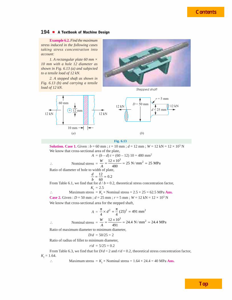
194 A Textbook of Machine Design
Stepped shaft
Example 6.2. Find the maximumstress induced in the following casestaking stress concentration intoaccount:
1. A rectangular plate 60 mm ×10 mm with a hole 12 diameter asshown in Fig. 6.13 (a) and subjectedto a tensile load of 12 kN.
2. A stepped shaft as shown inFig. 6.13 (b) and carrying a tensileload of 12 kN.
Fig. 6.13
Solution. Case 1. Given : b = 60 mm ; t = 10 mm ; d = 12 mm ; W = 12 kN = 12 × 103 NWe know that cross-sectional area of the plate,
A = (b – d) t = (60 – 12) 10 = 480 mm2
∴ Nominal stress =3
212 1025 N / mm 25 MPa
480
W
A
×= = =
Ratio of diameter of hole to width of plate,12
0.260
d
b= =
From Table 6.1, we find that for d / b = 0.2, theoretical stress concentration factor,Kt = 2.5
∴ Maximum stress = Kt × Nominal stress = 2.5 × 25 = 62.5 MPa Ans.Case 2. Given : D = 50 mm ; d = 25 mm ; r = 5 mm ; W = 12 kN = 12 × 103 N
We know that cross-sectional area for the stepped shaft,
A = 2 2 2(25) 491 mm4 4
dπ π× = =
∴ Nominal stress =3
212 1024.4 N / mm 24.4 MPa
491
W
A
×= = =
Ratio of maximum diameter to minimum diameter,
D/d = 50/25 = 2
Ratio of radius of fillet to minimum diameter,
r/d = 5/25 = 0.2
From Table 6.3, we find that for D/d = 2 and r/d = 0.2, theoretical stress concentration factor,Kt = 1.64.
∴ Maximum stress = Kt × Nominal stress = 1.64 × 24.4 = 40 MPa Ans.

Variable Stresses in Machine Parts 195
6.16 Fatigue Stress Concentration FactorWhen a machine member is subjected to cyclic or fatigue loading, the value of fatigue stress
concentration factor shall be applied instead of theoretical stress concentration factor. Since thedetermination of fatigue stress concentration factor is not an easy task, therefore from experimentaltests it is defined as
Fatigue stress concentration factor,
Kf =Endurance limit without stress concentration
Endurance limit with stress concentration
6.17 Notch SensitivityIn cyclic loading, the effect of the notch or the fillet is usually less than predicted by the use of
the theoretical factors as discussed before. The difference depends upon the stress gradient in theregion of the stress concentration and on the hardness of the material. The term notch sensitivity isapplied to this behaviour. It may be defined as the degree to which the theoretical effect of stressconcentration is actually reached. The stress gradient depends mainly on the radius of the notch, holeor fillet and on the grain size of the material. Since the extensive data for estimating the notch sensitivityfactor (q) is not available, therefore the curves, as shown in Fig. 6.14, may be used for determiningthe values of q for two steels.
Fig. 6.14. Notch sensitivity.
When the notch sensitivity factor q is used in cyclic loading, then fatigue stress concentrationfactor may be obtained from the following relations:
q =– 1
–1f
t
K
K
or Kf = 1 + q (Kt – 1) ...[For tensile or bending stress]
and Kfs = 1 + q (Kts – 1) ...[For shear stress]
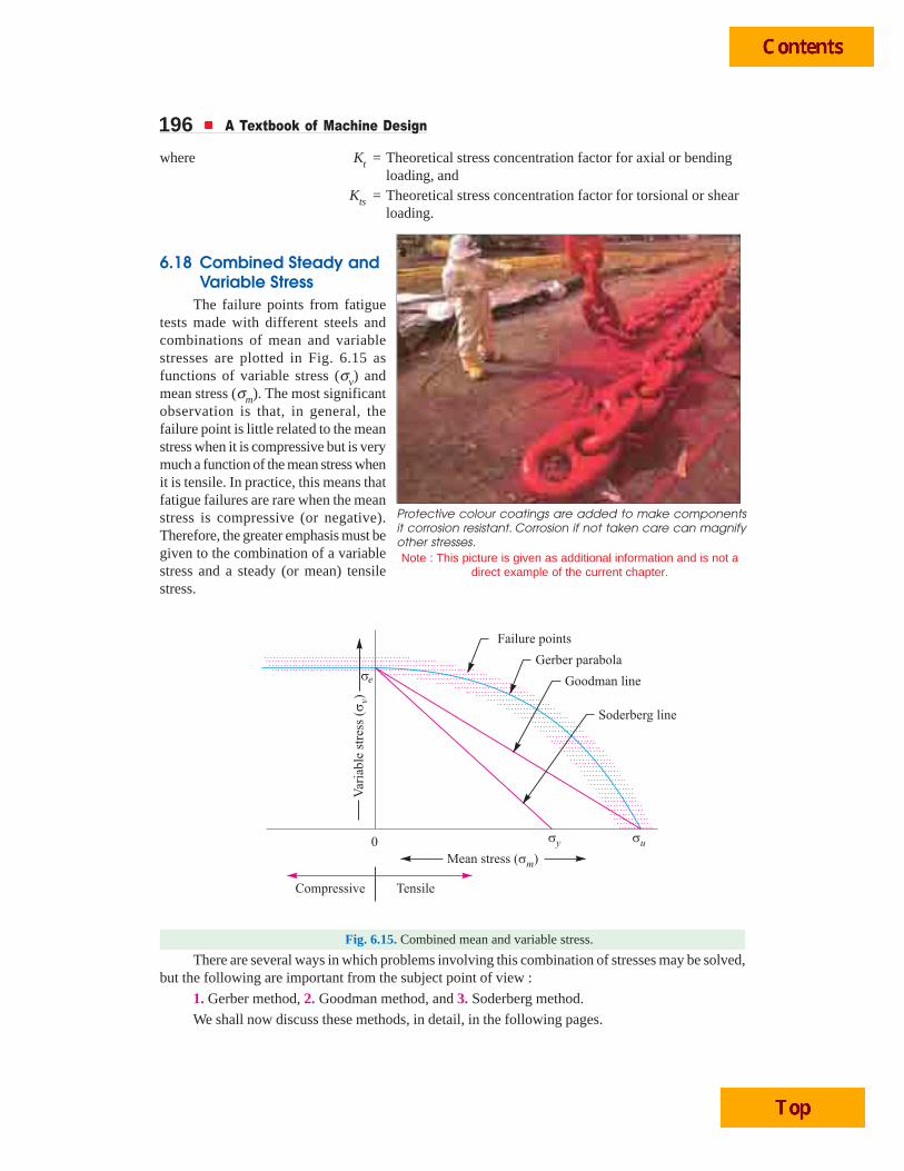
196 A Textbook of Machine Design
where Kt = Theoretical stress concentration factor for axial or bendingloading, and
Kts = Theoretical stress concentration factor for torsional or shearloading.
6.18 Combined Steady andVariable Stress
The failure points from fatiguetests made with different steels andcombinations of mean and variablestresses are plotted in Fig. 6.15 asfunctions of variable stress (σv) andmean stress (σm). The most significantobservation is that, in general, thefailure point is little related to the meanstress when it is compressive but is verymuch a function of the mean stress whenit is tensile. In practice, this means thatfatigue failures are rare when the meanstress is compressive (or negative).Therefore, the greater emphasis must begiven to the combination of a variablestress and a steady (or mean) tensilestress.
Fig. 6.15. Combined mean and variable stress.
There are several ways in which problems involving this combination of stresses may be solved,but the following are important from the subject point of view :
1. Gerber method, 2. Goodman method, and 3. Soderberg method.
We shall now discuss these methods, in detail, in the following pages.
Protective colour coatings are added to make componentsit corrosion resistant. Corrosion if not taken care can magnifyother stresses.Note : This picture is given as additional information and is not a
direct example of the current chapter.

Variable Stresses in Machine Parts 197
6.19 Gerber Method forCombination of Stresses
The relationship between variablestress (σv) and mean stress (σm) for axial andbending loading for ductile materials areshown in Fig. 6.15. The point σe representsthe fatigue strength corresponding to the caseof complete reversal (σm = 0) and the pointσu represents the static ultimate strengthcorresponding to σv = 0.
A parabolic curve drawn between theendurance limit (σe) and ultimate tensilestrength (σu) was proposed by Gerber in1874. Generally, the test data for ductilematerial fall closer to Gerber parabola asshown in Fig. 6.15, but because of scatter inthe test points, a straight line relationship (i.e.Goodman line and Soderberg line) is usuallypreferred in designing machine parts.
According to Gerber, variable stress,
σv = σe
21
. .. .
m
u
F SF S
⎡ ⎤σ⎛ ⎞−⎢ ⎥⎜ ⎟σ⎝ ⎠⎢ ⎥⎣ ⎦
or
21
. .. .
m v
u e
F SF S
σ σ⎛ ⎞= +⎜ ⎟σ σ⎝ ⎠...(i)
where F.S. = Factor of safety,
σm = Mean stress (tensile or compressive),
σu = Ultimate stress (tensile or compressive), and
σe = Endurance limit for reversal loading.
Considering the fatigue stressconcentration factor (Kf), the equation (i) maybe written as
21
. .. .
v fm
u e
KF S
F S
σ ×σ⎛ ⎞= +⎜ ⎟σ σ⎝ ⎠
6.20 Goodman Method forCombination of Stresses
A straight line connecting the endurancelimit (σe) and the ultimate strength (σu), asshown by line AB in Fig. 6.16, follows thesuggestion of Goodman. A Goodman line isused when the design is based on ultimatestrength and may be used for ductile or brittlematerials.
In Fig. 6.16, line AB connecting σe and
Liquid refrigerant absorbs heat as it vaporizes inside theevaporator coil of a refrigerator. The heat is releasedwhen a compressor turns the refrigerant back to liquid.
Note : This picture is given as additional information and isnot a direct example of the current chapter.
Fig. 6.16. Goodman method.
Evaporator
Gas flow
Fins radiate heat
Liquid flow
Condenser
Compressor

198 A Textbook of Machine Design
* Here we have assumed the same factor of safety (F.S.) for the ultimate tensile strength (σu) and endurancelimit (σe). In case the factor of safety relating to both these stresses is different, then the following relationmay be used :
1/ ( . .) / ( . .)
σ σ= −
σ σv m
F S F Se e u uwhere (F.S.)e = Factor of safety relating to endurance limit, and
(F.S.)u = Factor of safety relating to ultimate tensile strength.
σu is called Goodman's failure stress line. If a suitable factor of safety (F.S.) is applied to endurancelimit and ultimate strength, a safe stress line CD may be drawn parallel to the line AB. Let us considera design point P on the line CD.
Now from similar triangles COD and PQD,
PQ QD
CO OD=
OD OQ
OD
−= 1 –OQ
OD= ...(Q QD = OD – OQ)
∴ 1/ . . / . .
σ σ= −
σ σv m
e uF S F S
11
. . / . . . .e m m
v eu uF S F S F S
σ σ σ⎡ ⎤ ⎡ ⎤σ = − = σ −⎢ ⎥ ⎢ ⎥σ σ⎣ ⎦ ⎣ ⎦
or1
. .m v
u eF S
σ σ= +
σ σ...(i)
This expression does not include the effect of stress concentration. It may be noted that forductile materials, the stress concentration may be ignored under steady loads.
Since many machine and structural parts that are subjected to fatigue loads contain regions ofhigh stress concentration, therefore equation (i) must be altered to include this effect. In such cases,the fatigue stress concentration factor (Kf) is used to multiply the variable stress (σv). The equation (i)may now be written as
1
. .v fm
u e
K
F S
σ ×σ= +
σ σ...(ii)
where F.S. = Factor of safety,σm = Mean stress,σu = Ultimate stress,σv = Variable stress,σe = Endurance limit for reversed loading, andKf = Fatigue stress concentration factor.
Considering the load factor, surface finish factor and size factor, the equation (ii) may bewritten as
1
. .v f v fm m
u eb sur sz u e b sur sz
K K
F S K K K K K
σ × σ ×σ σ= + = +σ σ × × σ σ × × ×
...(iii)
=v fm
u e sur sz
K
K K
σ ×σ+
σ σ × × ...(Q σeb = σe × Kb and Kb = 1)
where Kb = Load factor for reversed bending load,
Ksur = Surface finish factor, and
Ksz = Size factor.
∗

Variable Stresses in Machine Parts 199Notes : 1. The equation (iii) is applicable to ductile materials subjected to reversed bending loads (tensile orcompressive). For brittle materials, the theoretical stress concentration factor (Kt) should be applied to the meanstress and fatigue stress concentration factor (Kf) to the variable stress. Thus for brittle materials, the equation(iii) may be written as
1
. .
σ ×σ ×= +σ σ × ×
v fm t
u eb sur sz
KK
F S K K...(iv)
2. When a machine component is subjected to a load other than reversed bending, then the endurancelimit for that type of loading should be taken into consideration. Thus for reversed axial loading (tensile orcompressive), the equations (iii) and (iv) may be written as
1
. .
σ ×σ= +σ σ × ×
v fm
u ea sur sz
K
F S K K...(For ductile materials)
and1
. .
σ ×σ ×= +σ σ × ×
v fm t
u ea sur sz
KK
F S K K...(For brittle materials)
Similarly, for reversed torsional or shear loading,
1
. .
τ ×τ= +τ τ × ×
v fsm
u e sur sz
K
F S K K...(For ductile materials)
and1
. .v fsm ts
u e sur sz
KK
F S K K
τ ×τ ×= +
τ τ × × ...(For brittle materials)
where suffix ‘s’denotes for shear.
For reversed torsional or shear loading, the values of ultimate shear strength (τu) and endurance shearstrength (τe) may be taken as follows:
τu = 0.8 σu; and τe = 0.8 σe
6.21 Soderberg Method for Combination of StressesA straight line connecting the endurance limit (σe) and the yield strength (σy), as shown by the
line AB in Fig. 6.17, follows the suggestion of Soderberg line. This line is used when the design isbased on yield strength.
Note : This picture is given as additional information and is not a direct example of the current chapter.
In this central heating system, a furnace burns fuel to heat water in a boiler. A pump forces the hotwater through pipes that connect to radiators in each room. Water from the boiler also heats the hotwater cylinder. Cooled water returns to the boiler.
Overflow pipeMainssupply
Hot watercylinderWater
tank Controlvalve
Radiator
Pump
Heat exchangerGas burner
Boiler Insulation
Flue
Air inlet

200 A Textbook of Machine Design
Proceeding in the same way as discussedin Art 6.20, the line AB connecting σe and σy, asshown in Fig. 6.17, is called Soderberg's failurestress line. If a suitable factor of safety (F.S.) isapplied to the endurance limit and yield strength,a safe stress line CD may be drawn parallel tothe line AB. Let us consider a design point P onthe line CD. Now from similar triangles CODand PQD,
PQ QD OD OQ
CO OD OD
−= =
= 1OQ
OD−
...(Q QD = OD – OQ)
∴ 1/ . . / . .
v m
e yF S F S
σ σ= −
σ σ
or1
1. . / . . . .e m m
v ey yF S F S F S
σ σ σ⎡ ⎤ ⎡ ⎤σ = − = σ −⎢ ⎥ ⎢ ⎥σ σ⎣ ⎦ ⎣ ⎦
∴1
. .m v
y eF S
σ σ= +
σ σ...(i)
For machine parts subjected to fatigue loading, the fatigue stress concentration factor (Kf)should be applied to only variable stress (σv). Thus the equations (i) may be written as
1
. .v fm
y e
K
F S
σ ×σ= +
σ σ...(ii)
Considering the load factor, surface finish factor and size factor, the equation (ii) may bewritten as
1
. .v fm
y eb sur sz
K
F S K K
σ ×σ= +
σ σ × ×...(iii)
Since σeb = σe × Kb and Kb = 1 for reversed bending load, therefore σeb = σe may be substitutedin the above equation.
Notes: 1. The Soderberg method is particularly used for ductile materials. The equation (iii) is applicable toductile materials subjected to reversed bending load (tensile or compressive).
2. When a machine component is subjected to reversed axial loading, then the equation (iii) may bewritten as
1
. .
σ ×σ= +σ σ × ×
v fm
y ea sur sz
K
F S K K
3. When a machine component is subjected to reversed shear loading, then equation (iii) may bewritten as
1
. .
τ ×τ= +τ τ × ×
v fsm
y e sur sz
K
F S K K
where K f s is the fatigue stress concentration factor for reversed shear loading. The yield strength in shear (τy)may be taken as one-half the yield strength in reversed bending (σy).
Fig. 6.17. Soderberg method.

Variable Stresses in Machine Parts 201Example 6.3. A machine component is
subjected to a flexural stress which fluctuatesbetween + 300 MN/m2 and – 150 MN/m2.Determine the value of minimum ultimate strengthaccording to 1. Gerber relation; 2. ModifiedGoodman relation; and 3. Soderberg relation.
Take yield strength = 0.55 Ultimate strength;Endurance strength = 0.5 Ultimate strength; andfactor of safety = 2.
Solution. Given : σ1 = 300 MN/m2 ;σ2 = – 150 MN/m2 ; σy = 0.55 σu ; σe = 0.5 σu ;F.S. = 2
Let σu = Minimum ultimate strength in MN/m2.
We know that the mean or average stress,
21 2 300 ( 150)75 MN/m
2 2
σ + σ + −σ = = =m
and variable stress, 21 2 300 ( 150)225 MN/m
2 2vσ − σ − −σ = = =
1. According to Gerber relationWe know that according to Gerber relation,
21
. .. .
m v
u e
F SF S
σ σ⎛ ⎞= +⎜ ⎟σ σ⎝ ⎠2
2 2
11 250 4501 75 225 11 250 4502
2 0.5 ( ) ( )
+ σ⎛ ⎞= + = + =⎜ ⎟σ σ σσ σ⎝ ⎠u
u u uu u
(σu)2 = 22 500 + 900 σu
or (σu)2 – 900 σu – 22 500 = 0
∴ σu =2900 (900) 4 1 22 500 900 948.7
2 1 2
± + × × ±=×
= 924.35 MN/m2 Ans. ...(Taking +ve sign)
2. According to modified Goodman relation
We know that according to modified Goodman relation,
1
. .m v
u eF S
σ σ= +
σ σ
or1 75 225 525
2 0.5u u u
= + =σ σ σ
∴ σu = 2 × 525 = 1050 MN/m2 Ans.
3. According to Soderberg relation
We know that according to Soderberg relation,1
. .m v
y eF S
σ σ= +
σ σ
or1 75 255 586.36
2 0.55 0.5u u u
= + =σ σ σ
∴ σu = 2 × 586.36 = 1172.72 MN/m2 Ans.
Springs often undergo variable stresses.

202 A Textbook of Machine Design
Example 6.4. A bar of circular cross-section is subjected to alternating tensile forces varyingfrom a minimum of 200 kN to a maximum of 500 kN. It is to be manufactured of a material with anultimate tensile strength of 900 MPa and an endurance limit of 700 MPa. Determine the diameter ofbar using safety factors of 3.5 related to ultimate tensile strength and 4 related to endurance limitand a stress concentration factor of 1.65 for fatigue load. Use Goodman straight line as basis fordesign.
Solution. Given : Wmin = 200 kN ; Wmax = 500 kN ; σu = 900 MPa = 900 N/mm2 ; σe = 700 MPa= 700 N/mm2 ; (F.S.)u = 3.5 ; (F.S.)e = 4 ; Kf = 1.65
Let d = Diameter of bar in mm.
∴ Area, A = 2 2 20.7854 mm4
d dπ × =
We know that mean or average force,
Wm = 3500 200350 kN 350 10 N
2 2max minW W+ += = = ×
∴ Mean stress, σm =3 3
22 2
350 10 446 10N / mm
0.7854
× ×= =mW
A d d
Variable force, Wv = 3500 200150 kN 150 10 N
2 2max minW W− −= = = ×
∴ Variable stress, σv =3 3
22 2
150 10 191 10N / mm
0.7854vW
A d d
× ×= =
We know that according to Goodman's formula,
.1 –
/ ( . .) / ( . .)m fv
e e u u
K
F S F S
σσ=
σ σ3 3
2 2
191 10 446 101.65
1700 / 4 900 / 3.5
d d
× × ×= −
Paint Manufacture : A typical gloss paint is made by first mixingnatural oils and resins called alkyds. Thinner is added to makethe mixture easier to pump through a filter that removes anysolid particles from the blended liquids. Pigment is mixed intothe binder blend in a powerful mixer called a disperser.
Pigment and paint thin-ner added
Final adjustments madeFilter tankSetting tank
Mixingtank
Thinner added
Oil and resinblendedtogether
Disperser Bead mill Holding tank
Note : This picture is given as additional information and is not a direct example of the current chapter.

Variable Stresses in Machine Parts 203
2 2
1100 28601
d d= − or 2
1100 28601
d
+ =
∴ d 2 = 3960 or d = 62.9 say 63 mm Ans.Example 6.5. Determine the thickness of a 120 mm wide uniform plate for safe continuous
operation if the plate is to be subjected to a tensile load that has a maximum value of 250 kN and aminimum value of 100 kN. The properties of the plate material are as follows:
Endurance limit stress = 225 MPa, and Yield point stress = 300 MPa.
The factor of safety based on yield point may be taken as 1.5.
Solution. Given : b = 120 mm ; Wmax = 250 kN; Wmin = 100 kN ; σe = 225 MPa = 225 N/mm2 ;σy = 300 MPa = 300 N/mm2; F.S. = 1.5
Let t = Thickness of the plate in mm.
∴ Area, A = b × t = 120 t mm2
We know that mean or average load,
Wm = 3250 100175 kN = 175 × 10 N
2 2max minW W+ += =
∴ Mean stress, σm =3
2175 10N/mm
120mW
A t
×=
Variable load, Wv = 3250 10075 kN 75 10 N
2 2max minW W− −= = = ×
∴ Variable stress, σv =3
275 10N/mm
120vW
A t
×=
According to Soderberg’s formula,1
. .m v
y eF S
σ σ= +
σ σ3 31 175 10 75 10 4.86 2.78 7.64
1.5 120 300 120 225t t t t t
× ×= + = + =× ×
∴ t = 7.64 × 1.5 = 11.46 say 11.5 mm Ans.Example 6.6. Determine the diameter of a circular rod made of ductile material with a fatigue
strength (complete stress reversal), σe = 265 MPa and a tensile yield strength of 350 MPa. Themember is subjected to a varying axial load from Wmin = – 300 × 103 N to Wmax = 700 × 103 N andhas a stress concentration factor = 1.8. Use factor of safety as 2.0.
Solution. Given : σe = 265 MPa = 265 N/mm2 ; σy = 350 MPa = 350 N/mm2 ; Wmin = – 300 × 103 N ;Wmax = 700 × 103 N ; Kf = 1.8 ; F.S. = 2
Let d = Diameter of the circular rod in mm.
∴ Area, A = 2 2 20.7854 mm4
d dπ × =
We know that the mean or average load,
Wm =3 3
3700 10 ( 300 10 )200 10 N
2 2max minW W+ × + − ×= = ×
∴ Mean stress, σm =3 3
22 2
200 10 254.6 10N/mm
0.7854mW
A d d
× ×= =

204 A Textbook of Machine Design
Variable load, Wv =3 3
3700 10 ( 300 10 )500 10 N
2 2max minW W− × − − ×= = ×
∴ Variable stress, σv =3 3
22 2
500 10 636.5 10N/mm
0.7854vW
A d d
× ×= =
We know that according to Soderberg's formula,
1
. .v fm
y e
K
F S
σ ×σ= +
σ σ3 3
2 2 2 2 2
1 254.6 10 636.5 10 1.8 727 4323 5050
2 350 265d d d d d
× × ×= + = + =× ×
∴ d 2 = 5050 × 2 = 10 100 or d = 100.5 mm Ans.Example 6.7. A steel rod is subjected to a reversed axial load of 180 kN. Find the diameter of
the rod for a factor of safety of 2. Neglect column action. The material has an ultimate tensilestrength of 1070 MPa and yield strength of 910 MPa. The endurance limit in reversed bendingmay be assumed to be one-half of the ultimate tensile strength. Other correction factors may betaken as follows:
For axial loading = 0.7; For machined surface = 0.8 ; For size = 0.85 ; For stressconcentration = 1.0.
Solution. Given : Wmax = 180 kN ; Wmin = – 180 kN ; F.S. = 2 ; σu = 1070 MPa = 1070N/mm2; σy = 910 MPa = 910 N/mm2 ; σe = 0.5 σu ; Ka = 0.7 ; Ksur = 0.8 ; Ksz = 0.85 ; Kf = 1
Let d = Diameter of the rod in mm.
∴ Area, A = 2 2 20.7854 mm4
d dπ × =
We know that the mean or average load,
Wm =180 ( 180)
02 2
max minW W+ + −= =
∴ Mean stress, σm = 0mW
A=
Variable load, Wv = 3180 ( 180)180 kN 180 10 N
2 2max minW W− − −= = = ×
∴Variable stress, σv =3 3
22 2
180 10 229 10N/mm
0.7854vW
A d d
× ×= =
Endurance limit in reversed axial loading,
σea = σe × Ka = 0.5 σu × 0.7 = 0.35 σu ...(Q σe = 0.5 σu)
= 0.35 × 1070 = 374.5 N/mm2
We know that according to Soderberg's formula for reversed axial loading,
1
. .v fm
y ea sur sz
K
F S K K
σ ×σ= +
σ σ × ×3
2 2
1 229 10 1 9000
2 374.5 0.8 0.85d d
× ×= + =× × ×
∴ d 2 = 900 × 2 = 1800 or d = 42.4 mm Ans.

Variable Stresses in Machine Parts 205
Example 6.8. A circular bar of 500 mm length is supported freely at its two ends. It is actedupon by a central concentrated cyclic load having a minimum value of 20 kN and a maximum valueof 50 kN. Determine the diameter of bar by taking a factor of safety of 1.5, size effect of 0.85, surfacefinish factor of 0.9. The material properties of bar are given by : ultimate strength of 650 MPa, yieldstrength of 500 MPa and endurance strength of 350 MPa.
Solution. Given : l = 500 mm ; Wmin = 20 kN = 20 × 103 N ; Wmax = 50 kN = 50 × 103 N ;F.S. = 1.5 ; Ksz = 0.85 ; Ksur = 0.9 ; σu = 650 MPa = 650 N/mm2 ; σy = 500 MPa = 500 N/mm2 ;σe = 350 MPa = 350 N/mm2
Let d = Diameter of the bar in mm.
We know that the maximum bending moment,
Mmax =3
350 10 5006250 10 N-mm
4 4maxW l× × ×= = ×
and minimum bending moment,
Mmin =3
320 10 5002550 10 N -mm
4 4minW l× × ×= = ×
∴ Mean or average bending moment,
Mm =3 3
36250 10 2500 104375 10 N-mm
2 2max minM M+ × + ×= = ×
and variable bending moment,
Mv =3 3
36250 10 2500 101875 10 N -mm
2 2max minM M− × − ×= = ×
Section modulus of the bar,
Z =3 3 30.0982 mm
32d d
π × =
∴ Mean or average bending stress,
σm =3 6
23 3
4375 10 44.5 10N/mm
0.0982mM
Z d d
× ×= =
Layout of a military tank.
Note : This picture is given as additional information and is not a direct example of the current chapter.
Shells formain gun
Loader Engine
Drivingsprocket
Main gun
Machine gun
Rubber tyres
Driver
Gunner
Commander
Sighting equipment

206 A Textbook of Machine Design
and variable bending stress,
σv = 3 6
23 3
1875 10 19.1 10N/mm
0.0982vM
Z d d
× ×= =
We know that according to Goodman's formula,
1
. .v fm
u e sur sz
K
F S K K
σ ×σ= +σ σ × ×
6 6
3 3
1 44.5 10 19.1 10 1
1.5 650 350 0.9 0.85
× × ×= +× × × ×d d
...(Taking Kf = 1)
=3 3 3
3 3 3
68 10 71 10 139 10
d d d
× × ×+ =
∴ d 3 = 139 × 103 × 1.5 = 209 × 103 or d = 59.3 mm
and according to Soderberg's formula,
1
. .v fm
y e sur sz
K
F S K K
σ ×σ= +
σ σ × ×
6 6
3 3
1 44.5 10 19.1 10 1
1.5 500 350 0.9 0.85
× × ×= +× × × ×d d
...(Taking Kf = 1)
=3 3 3
3 3 3
89 10 71 10 160 10
d d d
× × ×+ =
∴ d 3 = 160 × 103 × 1.5 = 240 × 103 or d = 62.1 mm
Taking larger of the two values, we have d = 62.1 mm Ans.Example 6.9. A 50 mm diameter shaft is made from carbon steel having ultimate tensile
strength of 630 MPa. It is subjected to a torque which fluctuates between 2000 N-m to – 800 N-m.Using Soderberg method, calculate the factor of safety. Assume suitable values for any other dataneeded.
Solution. Given : d = 50 mm ; σu = 630 MPa = 630 N/mm2 ; Tmax = 2000 N-m ; Tmin = – 800 N-mWe know that the mean or average torque,
Tm = 32000 ( 800)600 N-m 600 10 N-mm
2 2max minT T+ + −= = = ×
∴ Mean or average shear stress,
τm = 3
23 3
16 16 600 1024.4 N / mm
(50)
× ×= =π π
mT
d... 3
16
π⎛ ⎞= × τ ×⎜ ⎟⎝ ⎠Q T d
Variable torque,
Tv = 32000 ( 800)1400 N-m 1400 10 N-mm
2 2max minT T− − −= = = ×
∴ Variable shear stress, τv = 3
23 3
16 16 1400 1057 N/mm
(50)vT
d
× ×= =π π
Since the endurance limit in reversed bending (σe) is taken as one-half the ultimate tensilestrength (i.e. σe = 0.5 σu) and the endurance limit in shear (τe) is taken as 0.55 σe, therefore
τe = 0.55 σe = 0.55 × 0.5 σu = 0.275 σu
= 0.275 × 630 = 173.25 N/mm2
Assume the yield stress (σy) for carbon steel in reversed bending as 510 N/mm2, surface finish
factor (Ksur) as 0.87, size factor (Ksz) as 0.85 and fatigue stress concentration factor (Kfs) as 1.
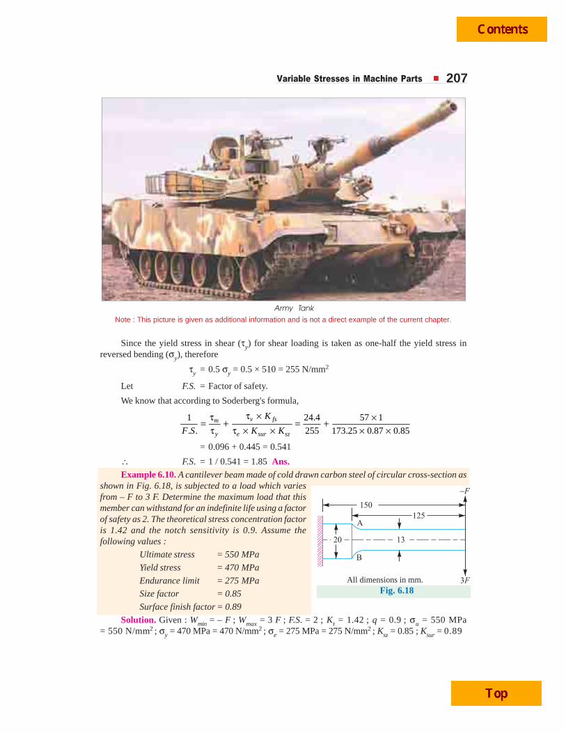
Variable Stresses in Machine Parts 207
Since the yield stress in shear (τy) for shear loading is taken as one-half the yield stress inreversed bending (σy), therefore
τy = 0.5 σy = 0.5 × 510 = 255 N/mm2
Let F.S. = Factor of safety.
We know that according to Soderberg's formula,
1 24.4 57 1
. . 255 173.25 0.87 0.85v fsm
y e sur sz
K
F S K K
τ ×τ ×= + = +τ τ × × × ×
= 0.096 + 0.445 = 0.541
∴ F.S. = 1 / 0.541 = 1.85 Ans.Example 6.10. A cantilever beam made of cold drawn carbon steel of circular cross-section as
shown in Fig. 6.18, is subjected to a load which variesfrom – F to 3 F. Determine the maximum load that thismember can withstand for an indefinite life using a factorof safety as 2. The theoretical stress concentration factoris 1.42 and the notch sensitivity is 0.9. Assume thefollowing values :
Ultimate stress = 550 MPa
Yield stress = 470 MPa
Endurance limit = 275 MPa
Size factor = 0.85
Surface finish factor = 0.89
Solution. Given : Wmin = – F ; Wmax = 3 F ; F.S. = 2 ; Kt = 1.42 ; q = 0.9 ; σu = 550 MPa= 550 N/mm2 ; σy = 470 MPa = 470 N/mm2 ; σe = 275 MPa = 275 N/mm2 ; Ksz = 0.85 ; Ksur = 0.89
Fig. 6.18
Note : This picture is given as additional information and is not a direct example of the current chapter.
Army Tank
All dimensions in mm.

208 A Textbook of Machine Design
The beam as shown in Fig. 6.18 is subjected to a reversed bending load only. Since the point Aat the change of cross section is critical, therefore we shall find the bending moment at point A.
We know that maximum bending moment at point A,
Mmax = Wmax × 125 = 3F × 125 = 375 F N-mmand minimum bending moment at point A,
Mmin = Wmin × 125 = – F × 125 = – 125 F N-mm∴ Mean or average bending moment,
Mm =375 ( 125 )
125 N -mm2 2
max minM M F FF
+ + −= =
and variable bending moment,
Mv =375 ( 125 )
250 N -mm2 2
max minM M F FF
− − −= =
Section modulus, Z =3 3 3(13) 215.7 mm
32 32d
π π× = = ...( Q d = 13 mm)
∴ Mean bending stress, σm = 21250.58 N/mm
215.7mM F
FZ
= =
and variable bending stress, σv = 22501.16 N/mm
215.7vM F
FZ
= =
Fatigue stress concentration factor,Kf = 1 + q (Kt – 1) = 1 + 0.9 (1.42 – 1) = 1.378
We know that according to Goodman’s formula
1
. .v fm
u e sur sz
K
F S K K
σ ×σ= +
σ σ × ×1 0.58 1.16 1.378
2 550 275 0.89 0.85
F F ×= +× ×
= 0.001 05 F + 0.007 68 F = 0.008 73 F
∴ F =1
57.3 N2 0.00873
=×
and according to Soderberg’s formula,
1
. .v fm
y e sur sz
K
F S K K
σ ×σ= +
σ σ × ×1 0.58 1.16 1.378
2 470 275 0.89 0.85
F F ×= +× ×
= 0.001 23 F + 0.007 68 F = 0.008 91 F
∴ F =1
56 N2 0.008 91
=×
Taking larger of the two values, we have F = 57.3 N Ans.Example 6.11. A simply supported beam has a concentrated load at the centre which fluctuates
from a value of P to 4 P. The span of the beam is 500 mm and its cross-section is circular with adiameter of 60 mm. Taking for the beam material an ultimate stress of 700 MPa, a yield stress of 500MPa, endurance limit of 330 MPa for reversed bending, and a factor of safety of 1.3, calculate themaximum value of P. Take a size factor of 0.85 and a surface finish factor of 0.9.
Solution. Given : Wmin = P ; Wmax = 4P ; L = 500 mm; d = 60 mm ; σu = 700 MPa = 700 N/mm2 ;
σy = 500 MPa = 500 N/mm2 ; σe = 330 MPa = 330 N/mm2 ; F.S. = 1.3 ; Ksz = 0.85 ; Ksur = 0.9

Variable Stresses in Machine Parts 209We know that maximum bending moment,
Mmax =4 500
500 N-mm4 4
maxW L PP
× ×= =
and minimum bending moment,
Mmin = 500
125 N-mm4 4
minW L PP
× ×= =
∴ Mean or average bending moment,
Mm =500 125
312.5 N-mm2 2
max minM M P PP
+ += =
and variable bending moment,
Mv =500 125
187.5 N-mm2 2
max minM M P PP
− −= =
Section modulus, Z =3 3 3 3(60) 21.21 10 mm
32 32d
π π× = = ×
∴ Mean bending stress,
σm =2
3
312.50.0147 N/mm
21.21 10mM P
PZ
= =×
and variable bending stress,
σv =2
3
187.50.0088 N/mm
21.21 10vM P
PZ
= =×
We know that according to Goodman’s formula,
1
. .v fm
u e sur sz
K
F S K K
σ ×σ= +
σ σ × ×1 0.0147 0.0088 1
1.3 700 330 0.9 0.85
P P ×= +× ×
...(Taking Kf = 1)
= 6 6 6
21 34.8 55.8
10 10 10
P P P+ =
∴ P =61 10
13 785 N 13.785 kN1.3 55.8
× = =
and according to Soderberg's formula,
1
. .v fm
y e sur sz
K
F S K K
σ ×σ= +
σ σ × ×
6 6 6
1 0.0147 0.0088 1 29.4 34.8 64.2
1.3 500 330 0.9 0.85 10 10 10
P P P P P×= + = + =× ×
∴ P =61 10
11 982 N 11.982 kN1.3 64.2
× = =
From the above, we find that maximum value of P = 13.785 kN Ans.
6.22 Combined Variable Normal Stress and Variable Shear StressWhen a machine part is subjected to both variable normal stress and a variable shear stress; then
it is designed by using the following two theories of combined stresses :
1. Maximum shear stress theory, and 2. Maximum normal stress theory.

210 A Textbook of Machine Design
We have discussed in Art. 6.21, that according to Soderberg's formula,
1
. .v fbm
y eb sur sz
K
F S K K
σ ×σ= +
σ σ × ×...(For reversed bending load)
Multiplying throughout by σy, we get
. .y v y fb
meb sur sz
K
F S K K
σ σ × σ ×= σ +
σ × ×The term on the right hand side of the above expression is known as equivalent normal stress
due to reversed bending.
∴ Equivalent normal stress due to reversed bending,v y fb
neb meb sur sz
K
K K
σ × σ ×σ = σ +
σ × ×...(i)
Similarly, equivalent normal stress due to reversed axial loading,v y fa
nea mea sur sz
K
K K
σ × σ ×σ = σ +
σ × ×. ..(ii)
and total equivalent normal stress,
σne = σneb + σnea = . .y
F S
σ...(iii)
We have also discussed in Art. 6.21, that for reversed torsional or shear loading,
1
. .v fsm
y e sur sz
K
F S K K
τ ×τ= +
τ τ × ×Multiplying throughout by τy, we get
. .y v y fs
me sur sz
K
F S K K
τ τ × τ ×= τ +
τ × ×The term on the right hand side of the above expression is known as equivalent shear stress.∴ Equivalent shear stress due to reversed torsional or shear loading,
v y fses m
e sur sz
K
K K
τ × τ ×τ = τ +
τ × ×...(iv)
The maximum shear stress theory is used in designing machine parts of ductile materials.According to this theory, maximum equivalent shear stress,
τes(max) =2 21
( ) 4 ( )2 . .
yne es F S
τσ + τ =
The maximum normal stress theory is used in designing machine parts of brittle materials.According to this theory, maximum equivalent normal stress,
σne(max) =2 21 1
( ) ( ) 4 ( )2 2 . .
σσ + σ + τ = y
ne ne es F SExample 6.12. A steel cantilever is 200 mm long. It is subjected to an axial load which varies
from 150 N (compression) to 450 N (tension) and also a transverse load at its free end which variesfrom 80 N up to 120 N down. The cantilever is of circular cross-section. It is of diameter 2d for thefirst 50 mm and of diameter d for the remaining length. Determine its diameter taking a factor ofsafety of 2. Assume the following values :
Yield stress = 330 MPaEndurance limit in reversed loading = 300 MPaCorrection factors = 0.7 in reversed axial loading
= 1.0 in reversed bending

Variable Stresses in Machine Parts 211
Stress concentration factor = 1.44 for bending
= 1.64 for axial loading
Size effect factor = 0.85
Surface effect factor = 0.90
Notch sensitivity index = 0.90
Solution. Given : l = 200 mm; Wa(max) = 450 N; Wa(min) = – 150 N ; Wt(max) = 120 N ;Wt(min) = – 80 N; F.S. =2 ; σy = 330 MPa = 330 N/mm2 ; σe = 300 MPa = 300 N/mm2 ;
Ka = 0.7; Kb = 1; Ktb = 1.44 ; Kta = 1.64; Ksz = 0.85 ; Ksur = 0.90 ; q = 0.90
First of all, let us find the equiva-lent normal stress for point A which iscritical as shown in Fig. 6.19. It is assumedthat the equivalent normal stress at thispoint will be the algebraic sum of theequivalent normal stress due to axial load-ing and equivalent normal stress due tobending (i.e. due to transverse load act-ing at the free end).
Let us first consider the reversedaxial loading. We know that mean oraverage axial load,
Wm =( ) ( ) 450 ( 150)
150 N2 2
a max a minW W+ + −= =
and variable axial load,
Wv =( ) ( ) 450 ( 150)
300 N2 2
a max a minW W− − −= =
∴ Mean or average axial stress,
σm =2
2 2
150 4 191N/mmmW
A d d
×= =π
... 2
4
π⎛ ⎞= ×⎜ ⎟⎝ ⎠Q A d
and variable axial stress,
σv =2
2 2
300 4 382N/mmvW
A d d
×= =π
We know that fatigue stress concentration factor for reversed axial loading,
Kfa = 1 + q (Kta – 1) = 1 + 0.9 (1.64 – 1) = 1.576
and endurance limit stress for reversed axial loading,
σea = σe × Ka = 300 × 0.7 = 210 N/mm2
We know that equivalent normal stress at point A due to axial loading,
σnea = σm + 2 2
191 382 330 1.576
210 0.9 0.85
v y fa
ea sur sz
K
K K d d
σ × σ × × ×= +σ × × × × ×
= 22 2 2
191 1237 1428N/mm
d d d+ =
Fig. 6.19

212 A Textbook of Machine Design
Now let us consider the reversed bending due totransverse load. We know that mean or average bend-ing load,
Wm = ( ) ( )
2
+t max t minW W
120 ( 80)20 N
2
+ −= =
and variable bending load,
Wv =( ) ( )
2
−t max t minW W
120 ( 80)
100 N2
− −= =
∴ Mean bending moment at point A,
Mm = Wm (l – 50) = 20 (200 – 50) = 3000 N-mm
and variable bending moment at point A,
Mv = Wv (l – 50) = 100 (200 – 50) = 15 000 N-mm
We know that section modulus,
Z =3 3 30.0982 mm
32d d
π × =
∴ Mean or average bending stress,
σm =2
3 3
3000 30 550N/mm
0.0982= =mM
Z d dand variable bending stress,
σv = 23 3
15 000 152 750N/mm
0.0982= =vM
Z d dWe know that fatigue stress concentration factor for reversed bending,
Kfb = 1 + q (Ktb – 1) = 1 + 0.9 (1.44 – 1) = 1.396
Since the correction factor for reversed bending load is 1 (i.e. Kb = 1), therefore the endurancelimit for reversed bending load,
σeb = σe . Kb = σe = 300 N/mm2
We know that the equivalent normal stress at point A due to bending,
σneb = σm 3 3
30 550 152 750 330 1.396
300 0.9 0.85
v y fb
eb sur sz
K
K K d d
σ × σ × × ×+ = +σ × × × × ×
= 23 3 3
30 550 306 618 337 168N/mm
d d d+ =
∴ Total equivalent normal stress at point A,
σne = σneb + σnea 2
3 2
337 168 1428N/mm
d d= + ...(i)
Machine transporter

Variable Stresses in Machine Parts 213We know that equivalent normal stress at point A,
σne =2330
165 N/mm. . 2y
F S
σ= = ...(ii)
Equating equations (i) and (ii), we have
33 2
337 168 1428165 or 337 168 + 1428 165+ = =d d
d d∴ 236.1 + d = 0.116 d3 or d = 12.9 mm Ans. ...(By hit and trial)
Example 6.13. A hot rolled steel shaft is subjected to a torsional moment that varies from330 N-m clockwise to 110 N-m counterclockwise and an applied bending moment at a critical sectionvaries from 440 N-m to – 220 N-m. The shaft is of uniform cross-section and no keyway is present atthe critical section. Determine the required shaft diameter. The material has an ultimate strength of550 MN/m2 and a yield strength of 410 MN/m2. Take the endurance limit as half the ultimate strength,factor of safety of 2, size factor of 0.85 and a surface finish factor of 0.62.
Solution. Given : Tmax = 330 N-m (clockwise) ; Tmin = 110 N-m (counterclockwise) = – 110 N-m(clockwise) ; Mmax = 440 N-m ; Mmin = – 220 N-m ; σu = 550 MN/m2 = 550 × 106 N/m2 ;
σy = 410 MN/m2 = 410 × 106 N/m2 ; σe = 1
2σu = 275 × 106 N/m2 ; F.S. = 2 ; Ksz = 0.85 ; Ksur = 0.62
Let d = Required shaft diameter in metres.
We know that mean torque,
Tm =330 ( 110)
110 N-m2 2
max minT T+ + −= =
and variable torque, Tv =330 ( 110)
220 N-m2 2
max minT T− − −= =
∴ Mean shear stress,
τm =2
3 3 3
16 16 110 560N/m
×= =π π
mT
d d dand variable shear stress,
τv =2
3 3 3
16 16 220 1120N/mvT
d d d
×= =π π
Since the endurance limit in shear (τe) is 0.55 σe, and yield strength in shear (τy) is 0.5 σy,therefore
τe = 0.55 × 275 × 106 = 151.25 × 10⁶ N/m2
and τy = 0.5 × 410 × 106 = 205 × 106 N/m2
We know that equivalent shear stress,
τes = τm + v y fs
e sur sz
K
K K
τ × ττ × ×
= 6
3 3 6
560 1120 205 10 1
151.25 10 0.62 0.85d d
× × ×+× × × ×
...(Taking Kfs = 1)
= 23 3 3
560 2880 3440N/m
d d d+ =
Mean or average bending moment,
Mm =440 ( 220)
110 N-m2 2
max minM M+ + −= =

214 A Textbook of Machine Design
and variable bending moment,
Mv =– 440 ( 220)
330 N-m2 2
max minM M − −= =
Section modulus, Z = 3 3 30.0982 m32
d dπ × =
∴ Mean bending stress,
σm =2
3 3
110 1120N/m
0.0982mM
Z d d= =
and variable bending stress,
σv =2
3 3
330 3360N/m
0.0982vM
Z d d= =
Since there is no reversed axial loading, therefore theequivalent normal stress due to reversed bending load,
σneb = σne = σm + v y fb
eb sur sz
K
K K
σ × σ ×σ × ×
= 6
3 3 6
1120 3360 410 10 1
275 10 0.62 0.85d d
× × ×+× × × ×
...(Taking Kfb = 1 and σeb = σe)
= 2
3 3 3
1120 9506 10626N/m
d d d+ =
We know that the maximum equivalent shear stress,
τes(max) = 2 21( ) 4 ( )
. . 2y
ne esF S
τ= σ + τ
2 26
3 3
205 10 1 10 625 34404
2 2
× ⎛ ⎞ ⎛ ⎞= +⎜ ⎟ ⎜ ⎟⎝ ⎠ ⎝ ⎠d d
205 × 106 × d 3 = 6 6 3113 10 4 11.84 10 12.66 10× + × × = ×
∴ d 3 =3
6 3
12.66 10 0.0617
205 10 10
× =×
or d =0.395
0.0395 m 39.5 say 40 mm10
= = Ans.
Example 6.14. A pulley is keyed to a shaft midway between two bearings. The shaft is made ofcold drawn steel for which the ultimate strength is 550 MPa and the yield strength is 400 MPa. Thebending moment at the pulley varies from – 150 N-m to + 400 N-m as the torque on the shaft variesfrom – 50 N-m to + 150 N-m. Obtain the diameter of the shaft for an indefinite life. The stressconcentration factors for the keyway at the pulley in bending and in torsion are 1.6 and 1.3 respectively.Take the following values:
Factor of safety = 1.5Load correction factors = 1.0 in bending, and 0.6 in torsionSize effect factor = 0.85
Surface effect factor = 0.88
Machine parts are often madeof alloys to improve theirmechanical properties.

Variable Stresses in Machine Parts 215Solution. Given : σu = 550 MPa = 550 N/mm2 ; σy = 400 MPa = 400 N/mm2 ;
Mmin = – 150 N-m; Mmax = 400 N-m ; Tmin = – 50 N-m ; Tmax = 150 N-m ; Kfb = 1.6 ; Kfs = 1.3 ;F.S. = 1.5 ; Kb = 1 ; Ks = 0.6 ; Ksz = 0.85 ; Ksur = 0.88
Let d = Diameter of the shaft in mm.
First of all, let us find the equivalent normal stress due to bending.
We know that the mean or average bending moment,
Mm = 3400 ( 150)125 N-m 125 10 N-mm
2 2max minM M+ + −= = = ×
and variable bending moment,
Mv = 3400 ( 150)275 N-m 275 10 N-mm
2 2max minM M− − −= = = ×
Section modulus, Z =3 3 30.0982 mm
32d d
π × =
∴ Mean bending stress,
σm= 3 3
23 3
125 10 1273 10N/mm
0.0982
× ×= =mM
Z d dand variable bending stress,
σv = 3 3
23 3
275 10 2800 10N/mm
0.0982
× ×= =vM
Z d dAssuming the endurance limit in reversed bending as one-half the ultimate strength and since
the load correction factor for reversed bending is 1 (i.e. Kb = 1), therefore endurance limit in reversedbending,
σeb = σe = 2550275 N/mm
2 2uσ
= =
Since there is no reversed axial loading, therefore equivalent normal stress due to bending,
σneb = σne = σm + v y fb
eb sur sz
K
K K
σ × σ ×σ × ×
=3 3
3 3
1273 10 2800 10 400 1.6
275 0.88 0.85d d
× × × ×+× × ×
=3 3 3
23 3 3
1273 10 8712 10 9985 10N/mm
d d d
× × ×+ =
Now let us find the equivalent shear stress due to torsional moment. We know that the meantorque,
Tm = 3150 ( 50)50 N-m 50 10 N-mm
2 2max minT T+ + −= = = ×
and variable torque, Tv = 3150 ( 50)100 N-m 100 10 N-mm
2 2max minT T− − −= = = ×
∴ Mean shear stress,
τm =3 3
23 3 3
16 16 50 10 255 10N/mmmT
d d d
× × ×= =π π

216 A Textbook of Machine Design
and variable shear stress,
τv =3 3
23 3 3
16 16 100 10 510 10N/mmvT
d d d
× × ×= =π π
Endurance limit stress for reversed torsional or shear loading,τe = σe × Ks = 275 × 0.6 = 165 N/mm2
Assuming yield strength in shear,τy = 0.5 σy = 0.5 × 400 = 200 N/mm2
We know that equivalent shear stress,
τes = τm + v y fs
e sur sz
K
K K
τ × τ ×τ × ×
=3 3
3 3
255 10 510 10 200 1.3
165 0.88 0.85d d
× × × ×+× × ×
=3 3 3
23 3 3
255 10 1074 10 1329 10N/mm
d d d
× × ×+ =and maximum equivalent shear stress,
τes(max) = 2 21( ) 4 ( )
. . 2y
ne esF S
τ= σ + τ
2 23 3 3
3 3 3
200 1 9985 10 1329 10 5165 104
1.5 2 d d d
⎛ ⎞ ⎛ ⎞× × ×= + =⎜ ⎟ ⎜ ⎟⎝ ⎠ ⎝ ⎠
∴ d 3 =35165 10 1.5
38 740 or 33.84 say 35 mm200
d× × = = Ans.
6.23 Application of Soderberg’s EquationWe have seen in Art. 6.21 that according to Soderberg's equation,
1
. .v fm
y e
K
F S
σ ×σ= +
σ σ...(i)
This equation may also be written as
1
. .m e v y f
y e
K
F S
σ × σ + σ × σ ×=
σ × σ
or F.S. =y e y
ym e v y fm f v
e
KK
σ × σ σ=
σσ × σ + σ × σ × ⎛ ⎞σ + × σ⎜ ⎟σ⎝ ⎠
...(ii)
Since the factor of safety based on yield strength is the ratio of the yield point stress to theworking or design stress, therefore from equation (ii), we may write
Working or design stress
= σm + y
f ve
Kσ⎛ ⎞
× σ⎜ ⎟σ⎝ ⎠...(iii)
Let us now consider the use of Soderberg's equation to a ductile material under the followingloading conditions.
1. Axial loadingIn case of axial loading, we know that the mean or average stress,
σm = Wm / A

Variable Stresses in Machine Parts 217and variable stress, σv = Wv / A
where Wm = Mean or average load,
Wv = Variable load, and
A = Cross-sectional area.
The equation (iii) may now be written as follows :
Working or design stress,
=
ym f v
y em vf
e
W K WW W
KA A A
σ⎛ ⎞+ ×⎜ ⎟σ σ⎛ ⎞ ⎝ ⎠+ × =⎜ ⎟σ⎝ ⎠
∴ F.S. =y
ym f v
e
A
W K W
σ ×σ⎛ ⎞
+ ×⎜ ⎟σ⎝ ⎠2. Simple bending
In case of simple bending, we know that thebending stress,
σb =.M y M
I Z= ...
⎛ ⎞=⎜ ⎟⎝ ⎠Q
IZ
y
∴ Mean or average bending stress,
σm = Mm / Z
and variable bending stress,
σv = Mv/ Z
where Mm = Mean bending moment,
Mv = Variable bending moment, and
Z = Section modulus.
The equation (iii) may now be written asfollows :
Working or design bending stress,
σb =σ⎛ ⎞
+ ×⎜ ⎟σ⎝ ⎠
ym vf
e
M MK
Z Z
σ⎛ ⎞+ ×⎜ ⎟σ⎝ ⎠=
ym f v
e
M K M
Z
= 3
32 ⎡ σ ⎤⎛ ⎞+ ×⎢ ⎥⎜ ⎟σπ ⎢ ⎥⎝ ⎠⎣ ⎦
ym f v
e
M K Md
... 3For circular shafts,32
π⎛ ⎞= ×⎜ ⎟⎝ ⎠Q Z d
∴ F.S. =
3
32
y
ym f v
e
M K Md
σ
⎡ σ ⎤⎛ ⎞+ ×⎢ ⎥⎜ ⎟σπ ⎝ ⎠⎣ ⎦
Note : This picture is given as additional informationand is not a direct example of the current chapter.
A large disc- shaped electromagnet hangs fromjib of this scrapyard crane. Steel and iron objectsfly towards the magnet when the current isswitched on. In this way, iron and steel can beseparated for recycling.

218 A Textbook of Machine Design
3. Simple torsion of circular shaftsIn case of simple torsion, we know that the torque,
T = 33
16or
16
Td
d
π × τ × τ =π
∴ Mean or average shear stress,
τm = 3
16 mT
dπ
and variable shear stress, τv = 3
16 vT
dπwhere Tm = Mean or average torque,
Tv = Variable torque, and
d = Diameter of the shaft.
The equation (iii) may now be written as follows :
Working or design shear stress,
τ = 3 3 3
16 16 16τ ⎡ τ ⎤⎛ ⎞ ⎛ ⎞+ × = + ×⎢ ⎥⎜ ⎟ ⎜ ⎟τ τπ π π ⎢ ⎥⎝ ⎠ ⎝ ⎠⎣ ⎦
y ym vfs m fs v
e e
T TK T K T
d d d
∴ F.S. =
3
16
y
ym fs v
e
T K Td
τ⎡ τ ⎤⎛ ⎞
+ ×⎢ ⎥⎜ ⎟τ⎝ ⎠π ⎣ ⎦where Kfs = Fatigue stress concentration factor for torsional or shear loading.
Note : For shafts made of ductile material, τy = 0.5 σy, and τe = 0.5 σe may be taken.
4. Combined bending and torsion of circular shaftsIn case of combined bending and torsion of circular shafts, the maximum shear stress theory
may be used. According to this theory, maximum shear stress,
τmax =2 21
( ) 4. . 2y
bF S
τ= σ + τ
=
2 2
3 3
1 32 164
2
⎡ ⎤ ⎡ ⎤⎧ σ ⎫ ⎧ τ ⎫⎛ ⎞ ⎛ ⎞⎪ ⎪ ⎪ ⎪+ × + + ×⎢ ⎥ ⎢ ⎥⎨ ⎬ ⎨ ⎬⎜ ⎟ ⎜ ⎟σ τπ π⎪ ⎪ ⎪ ⎪⎢ ⎥ ⎢ ⎥⎝ ⎠ ⎝ ⎠⎩ ⎭ ⎩ ⎭⎣ ⎦ ⎣ ⎦
y ym f v m fs v
e e
M K M T K Td d
=
2 2
3
16 y ym f v m fs v
e e
M K M T K Td
⎡ σ ⎤ ⎡ τ ⎤⎛ ⎞ ⎛ ⎞+ × + + ×⎢ ⎥ ⎢ ⎥⎜ ⎟ ⎜ ⎟σ τπ ⎢ ⎥ ⎢ ⎥⎝ ⎠ ⎝ ⎠⎣ ⎦ ⎣ ⎦
The majority of rotating shafts carry a steady torque and the loads remain fixed in space in bothdirection and magnitude. Thus during each revolution every fibre on the surface of the shaft under-goes a complete reversal of stress due to bending moment. Therefore for the usual case when Mm = 0,Mv = M, Tm = T and Tv = 0, the above equation may be written as
2
23
16
. .y y
fe
K M TF S d
τ ⎡ σ ⎤⎛ ⎞= × +⎢ ⎥⎜ ⎟σ⎝ ⎠π ⎣ ⎦
Note: The above relations apply to a solid shaft. For hollow shaft, the left hand side of the above equations mustbe multiplied by (1 – k4), where k is the ratio of inner diameter to outer diameter.

Variable Stresses in Machine Parts 219Example 6.15. A centrifugal blower rotates at 600 r.p.m. A belt drive is used to connect the
blower to a 15 kW and 1750 r.p.m. electric motor. The belt forces a torque of 250 N-m and a force of2500 N on the shaft. Fig. 6.20 shows the location of bearings, the steps in the shaft and the plane inwhich the resultant belt force and torque act. The ratio of the journal diameter to the overhung shaftdiameter is 1.2 and the radius of the fillet is 1/10th of overhung shaft diameter. Find the shaft diameter,journal diameter and radius of fillet to have a factor of safety 3. The blower shaft is to be machinedfrom hot rolled steel having the following values of stresses:
Endurance limit = 180 MPa; Yield point stress = 300 MPa; Ultimate tensile stress = 450 MPa.
Solution. Given: *NB = 600 r.p.m. ; *P = 15 kW; *NM = 1750 r.p.m. ; T = 250 N-m = 250 × 103
N-mm; F = 2500 N ; F.S. = 3; σe = 180 MPa = 180 N/mm2 ; σy = 300 MPa = 300 N/mm2 ; σu = 450MPa = 450 N/mm2
Fig. 6.20
Let D = Journal diameter,
d = Shaft diameter, and r = Fillet radius.
∴ Ratio of journal diameter to shaft diameter,
D/d = 1.2 ...(Given)
and radius of the fillet, r = 1/10 × Shaft diameter (d) = 0.1 d
∴ r/d = 0.1 ...(Given)
From Table 6.3, for D/d = 1.2 and r/d = 0.1, the theoretical stress concentration factor,
Kt = 1.62
The two points at which failure may occur are at the end of the keyway and at the shoulder fillet.The critical section will be the one with larger product of Kf × M. Since the notch sensitivity factor qis dependent upon the unknown dimensions of the notch and since the curves for notch sensitivityfactor (Fig. 6.14) are not applicable to keyways, therefore the product Kt × M shall be the basis ofcomparison for the two sections.
∴ Bending moment at the end of the keyway,
Kt × M = 1.6 × 2500 [100 – (25 + 10)] = 260 × 103 N-mm
...(Q Kt for key ways = 1.6)
and bending moment at the shoulder fillet,
Kt × M = 1.62 × 2500 (100 – 25) = 303 750 N-mm
Since Kt × M at the shoulder fillet is large, therefore considering the shoulder fillet as the criticalsection. We know that
2
23
16
. .y y
fe
K M TF S d
τ ⎡ σ ⎤⎛ ⎞= × +⎢ ⎥⎜ ⎟σπ ⎢ ⎥⎝ ⎠⎣ ⎦
* Superfluous data

220 A Textbook of Machine Design
23 2
3
0.5 300 16 300303750 (250 10 )
3 180
⎡× ⎛ ⎞= × + ×⎢⎜ ⎟⎝ ⎠⎣πd
... (Substituting, τy = 0.5 σy)
50 =3
33 3
16 2877 10565 10
d d
×× × =π
∴ d 3 = 2877 × 103/50 = 57 540 or d = 38.6 say 40 mm Ans.Note: Since r is known (because r/d = 0.1 or r = 0.1d = 4 mm), therefore from Fig. 6.14, the notch sensitivityfactor (q) may be obtained. For r = 4 mm, we have q = 0.93.
∴ Fatigue stress concentration factor,
Kf = 1 + q (Kt – 1) = 1 + 0.93 (1.62 – 1) = 1.58
Using this value of Kf instead of Kt, a new value of d may be calculated. We see that magnitudes of Kf andKt are very close, therefore recalculation will not give any improvement in the results already obtained.
EEEEEXEXEXEXEXERRRRRCISECISECISECISECISESSSSS
1. A rectangular plate 50 mm × 10 mm with a hole 10 mm diameter is subjected to an axial load of 10 kN.Taking stress concentration into account, find the maximum stress induced. [Ans. 50 MPa]
2. A stepped shaft has maximum diameter 45 mm and minimum diameter 30 mm. The fillet radius is 6mm. If the shaft is subjected to an axial load of 10 kN, find the maximum stress induced, taking stressconcentration into account. [Ans. 22 MPa]
3. A leaf spring in an automobile is subjected to cyclic stresses. The average stress = 150 MPa; variablestress = 500 MPa; ultimate stress = 630 MPa; yield point stress = 350 MPa and endurance limit = 150MPa. Estimate, under what factor of safety the spring is working, by Goodman and Soderberg formulae.
[Ans. 1.75, 1.3]
4. Determine the design stress for bolts in a cylinder cover where the load is fluctuating due to gaspressure. The maximum load on the bolt is 50 kN and the minimum is 30 kN. The load is unpredict-able and factor of safety is 3. The surface of the bolt is hot rolled and the surface finish factor is 0.9.
During a simple tension test and rotating beam test on ductile materials (40 C 8 steel annealed), thefollowing results were obtained :
Diameter of specimen = 12.5 mm; Yield strength = 240 MPa; Ultimate strength = 450 MPa; Endurancelimit = 180 MPa. [Ans. 65.4 MPa]
5. Determine the diameter of a tensile member of a circular cross-section. The following data is given :
Maximum tensile load = 10 kN; Maximum compressive load = 5 kN; Ultimate tensile strength = 600MPa; Yield point = 380 MPa; Endurance limit = 290 MPa; Factor of safety = 4; Stress concentrationfactor = 2.2 [Ans. 24 mm]
6. Determine the size of a piston rod subjected to a total load of having cyclic fluctuations from 15 kN incompression to 25 kN in tension. The endurance limit is 360 MPa and yield strength is 400 MPa. Takeimpact factor = 1.25, factor of safety = 1.5, surface finish factor = 0.88 and stress concentration factor= 2.25. [Ans. 35.3 mm]
7. A steel connecting rod is subjected to a completely reversed axial load of 160 kN. Suggest the suitablediameter of the rod using a factor of safety 2. The ultimate tensile strength of the material is 1100MPa, and yield strength 930 MPa. Neglect column action and the effect of stress concentration.
[Ans. 30.4 mm]
8. Find the diameter of a shaft made of 37 Mn 2 steel having the ultimate tensile strength as 600 MPa andyield stress as 440 MPa. The shaft is subjected to completely reversed axial load of 200 kN. Neglectstress concentration factor and assume surface finish factor as 0.8. The factor of safety may be takenas 1.5. [Ans. 51.7 mm]
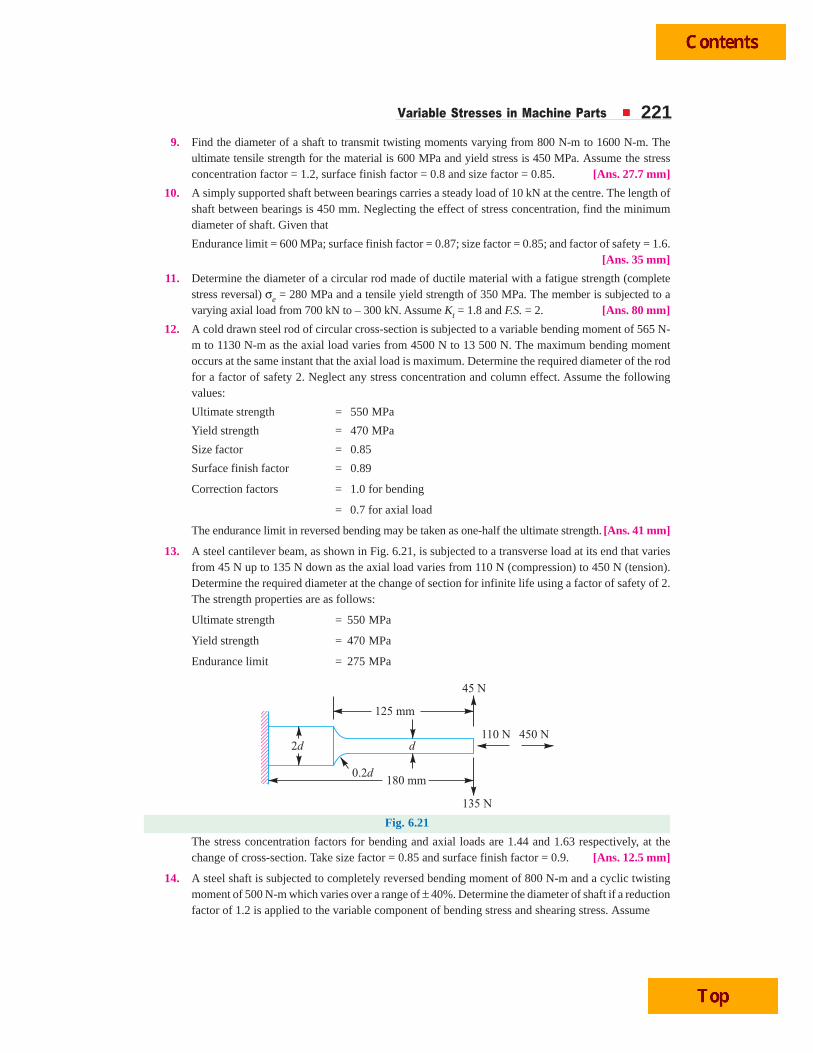
Variable Stresses in Machine Parts 2219. Find the diameter of a shaft to transmit twisting moments varying from 800 N-m to 1600 N-m. The
ultimate tensile strength for the material is 600 MPa and yield stress is 450 MPa. Assume the stressconcentration factor = 1.2, surface finish factor = 0.8 and size factor = 0.85. [Ans. 27.7 mm]
10. A simply supported shaft between bearings carries a steady load of 10 kN at the centre. The length ofshaft between bearings is 450 mm. Neglecting the effect of stress concentration, find the minimumdiameter of shaft. Given that
Endurance limit = 600 MPa; surface finish factor = 0.87; size factor = 0.85; and factor of safety = 1.6.[Ans. 35 mm]
11. Determine the diameter of a circular rod made of ductile material with a fatigue strength (completestress reversal) σe = 280 MPa and a tensile yield strength of 350 MPa. The member is subjected to avarying axial load from 700 kN to – 300 kN. Assume Kt = 1.8 and F.S. = 2. [Ans. 80 mm]
12. A cold drawn steel rod of circular cross-section is subjected to a variable bending moment of 565 N-m to 1130 N-m as the axial load varies from 4500 N to 13 500 N. The maximum bending momentoccurs at the same instant that the axial load is maximum. Determine the required diameter of the rodfor a factor of safety 2. Neglect any stress concentration and column effect. Assume the followingvalues:
Ultimate strength = 550 MPa
Yield strength = 470 MPa
Size factor = 0.85
Surface finish factor = 0.89
Correction factors = 1.0 for bending
= 0.7 for axial load
The endurance limit in reversed bending may be taken as one-half the ultimate strength. [Ans. 41 mm]
13. A steel cantilever beam, as shown in Fig. 6.21, is subjected to a transverse load at its end that variesfrom 45 N up to 135 N down as the axial load varies from 110 N (compression) to 450 N (tension).Determine the required diameter at the change of section for infinite life using a factor of safety of 2.The strength properties are as follows:
Ultimate strength = 550 MPa
Yield strength = 470 MPa
Endurance limit = 275 MPa
Fig. 6.21
The stress concentration factors for bending and axial loads are 1.44 and 1.63 respectively, at thechange of cross-section. Take size factor = 0.85 and surface finish factor = 0.9. [Ans. 12.5 mm]
14. A steel shaft is subjected to completely reversed bending moment of 800 N-m and a cyclic twistingmoment of 500 N-m which varies over a range of ± 40%. Determine the diameter of shaft if a reductionfactor of 1.2 is applied to the variable component of bending stress and shearing stress. Assume

222 A Textbook of Machine Design
(a) that the maximum bending and shearing stresses are in phase;
(b) that the tensile yield point is the limiting stress for steady state component;
(c) that the maximum shear strength theory can be applied; and
(d) that the Goodman relation is valid.
Take the following material properties:
Yield strength = 500 MPa ; Ultimate strength = 800 MPa ; Endurance limit = ± 400 MPa.
[Ans. 40 mm]
15. A pulley is keyed to a shaft midway between two anti-friction bearings. The bending moment at thepulley varies from – 170 N-m to 510 N-m and the torsional moment in the shaft varies from 55 N-mto 165 N-m. The frequency of the variation of the loads is the same as the shaft speed. The shaft ismade of cold drawn steel having an ultimate strength of 540 MPa and a yield strength of 400 MPa.Determine the required diameter for an indefinite life. The stress concentration factor for the keywayin bending and torsion may be taken as 1.6 and 1.3 respectively. The factor of safety is 1.5. Take sizefactor = 0.85 and surface finish factor = 0.88. [Ans. 36.5 mm]
[Hint. Assume σe = 0.5 σu; τy = 0.5 σy; τe = 0.55 σe]
QQQQQUEUEUEUEUESTSTSTSTSTIONSIONSIONSIONSIONS
1. Explain the following terms in connection with design of machine members subjected to variableloads:
(a) Endurance limit, (b) Size factor,
(c) Surface finish factor, and (d) Notch sensitivity.
2. What is meant by endurance strength of a material? How do the size and surface condition of acomponent and type of load affect such strength?
3. Write a note on the influence of various factors of the endurance limit of a ductile material.
4. What is meant by ̀ stress concentration'? How do you take it into consideration in case of a componentsubjected to dynamic loading?
5. Illustrate how the stress concentration in a component can be reduced.
6. Explain how the factor of safety is determined under steady and varying loading by different methods.
7. Write Soderberg's equation and state its application to different type of loadings.
8. What information do you obtain from Soderberg diagram?
OBJECTOBJECTOBJECTOBJECTOBJECTIVE IVE IVE IVE IVE TTTTT YPYPYPYPYPE QE QE QE QE QUEUEUEUEUESTSTSTSTSTIONSIONSIONSIONSIONS
1. The stress which vary from a minimum value to a maximum value of the same nature (i.e. tensile orcompressive) is called
(a) repeated stress (b) yield stress(c) fluctuating stress (d) alternating stress
2. The endurance or fatigue limit is defined as the maximum value of the stress which a polishedstandard specimen can withstand without failure, for infinite number of cycles, when subjected to(a) static load (b) dynamic load(c) static as well as dynamic load (d) completely reversed load
3. Failure of a material is called fatigue when it fails(a) at the elastic limit (b) below the elastic limit(c) at the yield point (d) below the yield point

Variable Stresses in Machine Parts 2234. The resistance to fatigue of a material is measured by
(a) elastic limit (b) Young's modulus(c) ultimate tensile strength (d) endurance limit
5. The yield point in static loading is ............... as compared to fatigue loading.(a) higher (b) lower (c) same
6. Factor of safety for fatigue loading is the ratio of(a) elastic limit to the working stress(b) Young's modulus to the ultimate tensile strength(c) endurance limit to the working stress(d) elastic limit to the yield point
7. When a material is subjected to fatigue loading, the ratio of the endurance limit to the ultimatetensile strength is(a) 0.20 (b) 0.35(c) 0.50 (d) 0.65
8. The ratio of endurance limit in shear to the endurance limit in flexure is(a) 0.25 (b) 0.40(c) 0.55 (d) 0.70
9. If the size of a standard specimen for a fatigue testing machine is increased, the endurance limit for thematerial will(a) have same value as that of standard specimen (b) increase (c) decrease
10. The residential compressive stress by way of surface treatment of a machine member subjected tofatigue loading(a) improves the fatigue life (b) deteriorates the fatigue life(c) does not affect the fatigue life (d) immediately fractures the specimen
11. The surface finish factor for a mirror polished material is(a) 0.45 (b) 0.65(c) 0.85 (d) 1
12. Stress concentration factor is defined as the ratio of(a) maximum stress to the endurance limit (b) nominal stress to the endurance limit(c) maximum stress to the nominal stress (d) nominal stress to the maximum stress
13. In static loading, stress concentration is more serious in(a) brittle materials (b) ductile materials(c) brittle as well as ductile materials (d) elastic materials
14. In cyclic loading, stress concentration is more serious in(a) brittle materials (b) ductile materials(c) brittle as well as ductile materials (d) elastic materials
15. The notch sensitivity q is expressed in terms of fatigue stress concentration factor Kf and theoreticalstress concentration factor Kt, as
(a)1
1
++
f
t
K
K (b)1
1
−−
f
t
K
K
(c)1
1
++
t
f
K
K (d)1
1
−−
t
f
K
K
ANSWEANSWEANSWEANSWEANSWERRRRRSSSSS
1. (c) 2. (d) 3. (d) 4. (d) 5. (a)
6. (c) 7. (c) 8. (c) 9. (c) 10. (a)
11. (d) 12. (c) 13. (a) 14. (b) 15. (b)